EP4019440A1 - Airlift - Google Patents
Airlift Download PDFInfo
- Publication number
- EP4019440A1 EP4019440A1 EP21401053.0A EP21401053A EP4019440A1 EP 4019440 A1 EP4019440 A1 EP 4019440A1 EP 21401053 A EP21401053 A EP 21401053A EP 4019440 A1 EP4019440 A1 EP 4019440A1
- Authority
- EP
- European Patent Office
- Prior art keywords
- airlift
- vertical
- conveying
- bulk material
- vertifeed
- Prior art date
- Legal status (The legal status is an assumption and is not a legal conclusion. Google has not performed a legal analysis and makes no representation as to the accuracy of the status listed.)
- Withdrawn
Links
- 239000002184 metal Substances 0.000 claims description 12
- 229910052751 metal Inorganic materials 0.000 claims description 12
- 238000009423 ventilation Methods 0.000 claims description 7
- 239000004744 fabric Substances 0.000 claims description 6
- 150000002739 metals Chemical class 0.000 claims description 2
- 230000001133 acceleration Effects 0.000 abstract description 3
- 239000013590 bulk material Substances 0.000 description 15
- 239000000243 solution Substances 0.000 description 4
- 230000032258 transport Effects 0.000 description 4
- 238000005273 aeration Methods 0.000 description 2
- 238000007789 sealing Methods 0.000 description 2
- 229910000831 Steel Inorganic materials 0.000 description 1
- 239000011449 brick Substances 0.000 description 1
- 238000010276 construction Methods 0.000 description 1
- 238000005243 fluidization Methods 0.000 description 1
- 238000000034 method Methods 0.000 description 1
- 229910001220 stainless steel Inorganic materials 0.000 description 1
- 239000010935 stainless steel Substances 0.000 description 1
- 239000010959 steel Substances 0.000 description 1
Images



Classifications
-
- B—PERFORMING OPERATIONS; TRANSPORTING
- B65—CONVEYING; PACKING; STORING; HANDLING THIN OR FILAMENTARY MATERIAL
- B65G—TRANSPORT OR STORAGE DEVICES, e.g. CONVEYORS FOR LOADING OR TIPPING, SHOP CONVEYOR SYSTEMS OR PNEUMATIC TUBE CONVEYORS
- B65G53/00—Conveying materials in bulk through troughs, pipes or tubes by floating the materials or by flow of gas, liquid or foam
- B65G53/04—Conveying materials in bulk pneumatically through pipes or tubes; Air slides
- B65G53/16—Gas pressure systems operating with fluidisation of the materials
- B65G53/18—Gas pressure systems operating with fluidisation of the materials through a porous wall
Definitions
- Airlifts are well known, in the innovative solution they are called VertiFeed.
- VertiFeed The structure of the VertiFeed is structurally simple, which makes it attractive for processes that require high availability from the vertical pneumatic transport.
- the functional principle is as follows:
- the conveying gas usually provided by a blower, flows into the VertiFeed from below.
- the cylindrical body of the VertiFeed is almost filled with bulk material.
- the bulk material is fluidized in the floor area in order to achieve a uniform feed of the bulk material to the conveying pipe.
- the inflowing conveying gas leaves the so-called conveying gas nozzle at high speed and captures the bulk material flowing into the nozzle and transports it into the vertical conveying pipe.
- Conveying heights of up to 150 m and conveying capacities of up to 1000 t/h can be achieved with the VertiFeed.
- the VertiFeed is fed continuously via air conveying troughs.
- the sealing of the conveying line back pressure to the environment/to the inlet takes place by means of the pressure generated by the bulk material column. This is proportional to the bulk material density and the bulk material level in the VertiFeed.
- the overall height of the VertiFeed is thus defined by the conveying capacity and the resulting back pressure in the conveying line, the gravitational acceleration and the bulk material filling level.
- the object of the invention is to develop an airlift which can be used for higher temperatures.
- An airlift was developed in such a way that there is ventilation at the bottom of the airlift via a ventilation connection and metal mesh, which can be exposed to a temperature of up to 1000 °C, and that the container in its construction is highly temperature-resistant up to a temperature of 1000 °C is executed.
- the airlift according to the invention is an infeed element for pneumatic conveying.
- the new state of the art means that this airlift can now be used up to 1000 °C. That What is special is that the container is made of temperature-resistant stainless steel and/or has a firebrick wall inside the airlift (1) and that the ventilation of the bulk material on the airlift floor is no longer realized with a fabric fabric, but with a metal fabric. This allows temperatures up to 1000 °C can be realized.
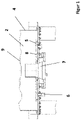
- the figures 1 and 3 show the innovative solution with the application of metal mesh (8).
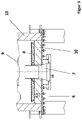
- the lower part of the airlift (1) is in the figure 3 shown, which is composed of the metal mesh (8) integrated into the floor inlet with the corresponding associated fastening frame (5) on the container (4). In the middle there is a nozzle (7). Above the
- the conveying pipe (9) is designed to convey the medium.
- the conveying gas usually air, flows through the nozzle (7).
- the inflowing conveying gas leaves the nozzle (7) at high speed and catches the bulk material (2) flowing into the nozzle (7) and transports it into the conveying pipe (9).
- the metal fabric (8) according to the invention is integrated in the fastening frame (5), the fluidizing gas flows in via the ventilation connection (6) and the bulk material (2) is thereby ventilated in the lower region of the container (4). Due to the metal mesh (8), temperatures of up to 1000 °C are possible or in connection with the structure of the air lift (1) with the container (4). Sintered metals are used for the metal mesh (8).
- the airlift (1) is designed in such a way that it is suitable for high temperatures of up to 1000° C. with the high-temperature-resistant container (4).
Landscapes
- Engineering & Computer Science (AREA)
- Mechanical Engineering (AREA)
- Filling Or Discharging Of Gas Storage Vessels (AREA)
- Woven Fabrics (AREA)
Abstract
Der VertiFeed arbeitet nach dem Airlift-Prinzip. Er dient dem vertikalen und vertikal/horizontalem Transport. In der Ausführung vertikal/horizontal ist der erste Förderabschnitt zwingend vertikal auszuführen, erst ab einer Beschleunigungsstrecke von 20xD (D=Förderrohrdurchmesser) darf ein horizontaler Förderabschnitt folgen.
Description
- Bekannt sind Airlifte, in der erfinderischen Lösung werden sie benannt mit VertiFeed.
- Der VertiFeed arbeitet nach dem Airlift-Prinzip. Er dient dem vertikalen und vertikal/horizontalem Transport. In der Ausführung vertikal/horizontal ist der erste Förderabschnitt zwingend vertikal auszuführen, erst ab einer Beschleunigungsstrecke von 20xD (D=Förderrohrdurchmesser) darf ein horizontaler Förderabschnitt folgen.
- Der Aufbau des VertiFeed ist konstruktiv einfach gestaltet, was ihn attraktiv für Prozesse macht, die eine hohe Verfügbarkeit an den vertikalen pneumatischen Transport legen.
- Das Funktionsprinzip ist wie folgt: Das Fördergas, in der Regel durch Gebläse bereitgestellt, strömt von unten in den VertiFeed ein. Der zylindrische Körper des VertiFeed ist nahezu mit Schüttgut gefüllt. Im Bodenbereich wird das Schüttgut fluidisiert, um einen gleichmäßigen Zulauf des Schüttgutes zum Förderrohr zu erzielen.
- Das einströmende Fördergas verlässt die sogenannte Fördergasdüse mit hoher Geschwindigkeit und erfasst das der Düse zufließende Schüttgut und transportiert es in das vertikale Förderrohr.
- Förderhöhen von bis zu 150 m, bei Förderleistungen bis zu 1000 t/h, können mit dem VertiFeed erzielt werden. Die Beschickung des VertiFeeds erfolgt kontinuierlich über in der Regel Luftförderrinnen.
- Leistungsmerkmale:
- keine bewegten Teile, dadurch höchste Verfügbarkeit
- geringe Investitionskosten
- geringster Verschleiß
- Förderleistungen bis zu 1000 t/h
- Förderhöhen bis zu 150 m
- Standard-Betriebstemperatur < 150 °C,
auf Anfrage bis zu 600 °C möglich - kontinuierlicher Betrieb
- Die Abdichtung des Förderleitungsrückdruckes zur Umgebung/zum Einlauf hin erfolgt mittels den durch die Schüttgutsäule erzeugten Druck. Dieser ist proportional der Schüttgutdichte und der Schüttgutfüllhöhe im VertiFeed. Die Gesamtbauhöhe des VertiFeeds wird somit durch die Förderleistung und den daraus resultierenden Förderleitungsrückdruck, der Erdbeschleunigung sowie durch die Schüttgutfüllhöhe definiert.
- Aufgabe der Erfindung ist es, einen Airlift zu entwickeln, welcher für höhere Temperaturen einsetzbar ist.
- Die Aufgabe wird erfindungsgemäß dadurch gelöst, dass der Patentanspruch 1 realisiert wird.
- Dabei wurde ein Airlift so entwickelt, dass eine untere Belüftung des Airliftes über einen Belüftungsanschluss und durch ein Metallgewebe, welches einer Temperatur bis 1000 °C ausgesetzt werden kann, gegeben ist und dass der Behälter in seiner Bauausführung hochtemperaturbeständig bis zu einer Temperatur von 1000 °C ausgeführt ist.
- Bei dem erfindungsgemäßen Airlift handelt es sich um ein Einschleusorgan für die pneumatische Förderung.
- Der neue Stand der Technik beinhaltet, dass dieser Airlift nun bis 1000 °C eingesetzt werden kann. Das Besondere ist, dass der Behälter aus einem temperaturbeständigen Edelstahl und/oder mit einer Schamottsteinbewandung im Innenraum des Airliftes (1) hergestellt wird und dass die Belüftung des Schüttgutes am Airlift-Boden nun nicht mehr mit einem Stoffgewebe, sondern mit einem Metallgewebe realisiert wird. Damit können Temperaturen bis 1000
°C realisiert werden. - Nachfolgend wird ein Ausführungsbeispiel beschrieben, wobei drei Zeichnungen dargestellt sind.
- Es zeigen die:
- Figur 1 -
- die erfinderische Lösung mit dem Gewebe,
- Figur 2 -
- eine Darstellung des Airliftes,
- Figur 3 -
- eine Darstellung des Airliftes im unteren Bereich,
- Figur 4 -
- Darstellung des Airliftes mit Schamottsteinen
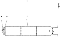
- Figur 5 -
- Allgemeine Darstellung des Airliftes,
- Figur 6 -
- Draufsicht des Airliftes.
- Die
Figuren 1 und3 zeigen die erfinderische Lösung mit der Anwendung des Metallgewebes (8). - Dabei ist der untere Bereich des Airliftes (1) in der
Figur 3 dargestellt, welcher zusammengesetzt ist aus dem in den Bodeneinlass integrierten Metallgewebe (8) mit dem entsprechenden dazugehörigen Befestigungsrahmen (5) an dem Behälter (4). In der Mitte ist eine Düse (7) gegeben. Oberhalb des - Austritts der Düse (7) unterhalb des Behälters (4) ist das Förderrohr (9) zur Weiterleitung des Mediums ausgeführt.
- Das Fördergas, i.d.R. Luft, strömt durch die Düse (7). Das einströmende Fördergas verlässt die Düse (7) mit hoher Geschwindigkeit und erfasst das der Düse (7) zufließende Schüttgut (2) und transportiert es in das Förderrohr (9).
- In dem Befestigungsrahmen (5) ist das erfindungsgemäße Metallgewebe (8) integriert, über den Belüftungsanschluß (6) strömt das Fluidisiergas ein und dadurch findet die Belüftung des Schüttgutes (2) im unteren Bereich des Behälters (4) statt. Auf Grund des Metallgewebes (8) sind Temperaturen bis zu 1000 °C möglich bzw. im Zusammenhang mit dem Aufbau des Airliftes (1) mit dem Behälter (4). Für das Metallgewebe (8) werden Sintermetalle verwendet.
- Erfindungsgemäß ist der Airlift (1) so ausgeführt, dass er für hohe Temperaturen bis zu 1000 °C mit dem hochtemperaturbeständigem Behälter (4) geeignet ist.
- Dabei sind zwei verschiedene Arten realisierbar:
- Ausmauerung mit Schamottsteinen (10),
- Ausführung in Hochtemperaturstahl.
- Erfindungsgemäß ist der Hochtemperatur-Airlift (1) durch Folgendes gekennzeichnet:
- Behälter (4) geeignet zur Anwendung von Temperaturen bis zu 1000 °C,
- Belüftung bzw. Fluidisierung über den Belüftungsanschluß (6) des Schüttgutes (2), welches über den Einlass Schüttgut (3) in den Behälter (4) gelangt, im Bodenbereich des Airliftes (1), damit das Schüttgut (2) der angeordneten Düse (7) zuströmen kann,
- Weiterhin ist es auch möglich, für das Metallgewebe (8) poröse Steine oder luftdurchlässige, temperaturfeste Strukturen zu verwenden.
-
Figur 3 und4 sind Darstellungen des Airlifts (1) und des unteren Bereichs des Airliftes, dabei ist ersichtlich, dass eine zusätzliche Schamottsteinschicht (10) für die Hochtemperatur-Anwendung an der gesamten Innenseite des Airliftes (1) und im unteren Bereich vorhanden ist. Mit dieser Schamottstein- Schicht (10) kann der Anwendungsbereich bis zu 1000 Grad Celsius für den Airlift (1) ausgeführt werden. DieFiguren 5 und6 zeigen eine seitliche- bzw. eine Draufsicht des Airliftes (1) als schematische Darstellung. -
- 1
- Airlift
- 2
- Schüttgut
- 3
- Einlass Schüttgut
- 4
- Behälter
- 5
- Befestigungsrahmen
- 6
- Belüftungsanschluss
- 7
- Düse
- 8
- Metallgewebe
- 9
- Förderrohr
- 10
- Schamottsteine
Claims (1)
- Airlift als Einschleussorgan in eine pneumatische Förderung bekannter Bauart, wobei der untere Innenraum des Airliftes von unten über ein Stoffgewebe belüftet ist und der Behälter in seiner Bauausführung hochtemperaturbeständig ist, dadurch gekennzeichnet, dass eine untere Belüftung des Airliftes (1) über einen Belüftungsanschluss (6) über ein Metallgewebe (8), welches einer Temperatur bis 1000 °C ausgesetzt werden kann, gegeben ist und dafür Sintermetalle verwendet werden.
Applications Claiming Priority (1)
| Application Number | Priority Date | Filing Date | Title |
|---|---|---|---|
| DE102020133793.0A DE102020133793A1 (de) | 2020-12-16 | 2020-12-16 | Airlift |
Publications (1)
| Publication Number | Publication Date |
|---|---|
| EP4019440A1 true EP4019440A1 (de) | 2022-06-29 |
Family
ID=79730156
Family Applications (1)
| Application Number | Title | Priority Date | Filing Date |
|---|---|---|---|
| EP21401053.0A Withdrawn EP4019440A1 (de) | 2020-12-16 | 2021-12-09 | Airlift |
Country Status (2)
| Country | Link |
|---|---|
| EP (1) | EP4019440A1 (de) |
| DE (1) | DE102020133793A1 (de) |
Citations (3)
| Publication number | Priority date | Publication date | Assignee | Title |
|---|---|---|---|---|
| CN2317217Y (zh) * | 1997-01-14 | 1999-05-05 | 冶金工业部钢铁研究总院 | 高效仓式泵输粉装置 |
| EP1623941A1 (de) * | 2004-08-05 | 2006-02-08 | Alcan Technology & Management Ltd. | Vorrichtung und Verfahren zur pneumatischen Beförderung von Schüttgüten im Dichtstromverfahren |
| WO2010127771A1 (en) * | 2009-05-08 | 2010-11-11 | Outotec Oyj | Device for transporting bulk materials |
Family Cites Families (5)
| Publication number | Priority date | Publication date | Assignee | Title |
|---|---|---|---|---|
| DE7022424U (de) | 1971-09-23 | Mannesmann Ag | Pneumatische Fördereinrichtung für feinkörnige oder staubförmige Schüttgüter | |
| US2770503A (en) | 1951-02-16 | 1956-11-13 | Socony Mobil Oil Co Inc | Method and apparatus for pneumatic transfer of granular contact materials |
| GB1026826A (en) | 1964-10-29 | 1966-04-20 | Ducon Co | Conveying finely divided solids |
| DE3901110A1 (de) | 1989-01-16 | 1990-07-19 | Krupp Polysius Ag | Pneumatischer senkrechtfoerderer |
| DE202014101757U1 (de) | 2014-04-14 | 2014-06-13 | Ludwig Bräutigam | Brenneinsatz für Sturzbrandöfen |
-
2020
- 2020-12-16 DE DE102020133793.0A patent/DE102020133793A1/de not_active Withdrawn
-
2021
- 2021-12-09 EP EP21401053.0A patent/EP4019440A1/de not_active Withdrawn
Patent Citations (3)
| Publication number | Priority date | Publication date | Assignee | Title |
|---|---|---|---|---|
| CN2317217Y (zh) * | 1997-01-14 | 1999-05-05 | 冶金工业部钢铁研究总院 | 高效仓式泵输粉装置 |
| EP1623941A1 (de) * | 2004-08-05 | 2006-02-08 | Alcan Technology & Management Ltd. | Vorrichtung und Verfahren zur pneumatischen Beförderung von Schüttgüten im Dichtstromverfahren |
| WO2010127771A1 (en) * | 2009-05-08 | 2010-11-11 | Outotec Oyj | Device for transporting bulk materials |
Also Published As
| Publication number | Publication date |
|---|---|
| DE102020133793A1 (de) | 2022-06-23 |
Similar Documents
| Publication | Publication Date | Title |
|---|---|---|
| DE3741935C2 (de) | Verfahren zum Steuern der Kühlwirkung eines Partikelkühlers für einen zirkulierenden Wirbelschichtreaktor und regelbarer Partikelkühler | |
| DE69231941T2 (de) | Verfahren zur Behandlung von Gasen und körnigen Feststoffen in einer Wirbelschicht | |
| DE60318822T2 (de) | Extraktor/kühler für lose materialien durch verwendung eines förderbands, das mit bohrungen und flügeln versehenen platten ausgestattet ist | |
| DE202005021660U1 (de) | Vorrichtung zur geregelten Zufuhr von Brennstaub in einem Flugstromvergaser | |
| DE2800268A1 (de) | Verfahren und vorrichtung zur kontinuierlichen entfernung heisser feinteiliger feststoffe aus einem wirbelschichtreaktor unter kuehlung und entspannung | |
| EP2655271B1 (de) | Vorrichtung zum vorwärmen von beschickungsgut für glasschmelzanlagen | |
| EP4019440A1 (de) | Airlift | |
| DE2140508A1 (de) | Luftfuhrungsverfahren | |
| DE2258245A1 (de) | Tunnelofen | |
| DE3050391T1 (de) | Aeration feeder for coal dust supply to blast furnace hearth | |
| DE2122137A1 (de) | Hochtemperatur-Wärmeaustauscher, Heissblasanlage sowie Verfahren zum Betrieb eines Hochtemperatur-Wärmeaustauschers | |
| DE973557C (de) | Verfahren und Einrichtung zum magnetisierenden Reduzieren von Eisenerz | |
| JP5386865B2 (ja) | 予熱機 | |
| DE3412776C2 (de) | ||
| AT20482B (de) | Ofen zum Rösten von feinzerteiltem Erz, Brennen von Dolomit usw. | |
| CN107744998B (zh) | 一种环保型烟气收集调节控制装置及其应用 | |
| EP3999452A1 (de) | Fördern eines förderguts | |
| FI103905B (sv) | Förfarande för inmatning av avlut i en sodapanna | |
| DE957839C (de) | Schachtofen mit Beheizung durch Verbrennen von Beschickungskohle für die Durchführung von Reduktionsprozessen | |
| DE1197384B (de) | Vorrichtung zum Foerdern von pulverfoermigem oder feinkoernigem Gut | |
| DE972519C (de) | Verfahren und Anlage zur Anreicherung von Eisenerzen | |
| DE2925322A1 (de) | Staubfliessvorrichtung | |
| DE1756693C3 (de) | Pneumatische Vorrichtung zum Heben fester, körniger Stoffe mittels Druckgas als Fördermittel | |
| DE973347C (de) | Verfahren zum Austragen von Waermetraegern | |
| DE10200960A1 (de) | Vorrichtung zur Schleusung eines heißen mehlförmigen Gutes |
Legal Events
| Date | Code | Title | Description |
|---|---|---|---|
| PUAI | Public reference made under article 153(3) epc to a published international application that has entered the european phase |
Free format text: ORIGINAL CODE: 0009012 |
|
| STAA | Information on the status of an ep patent application or granted ep patent |
Free format text: STATUS: THE APPLICATION HAS BEEN PUBLISHED |
|
| AK | Designated contracting states |
Kind code of ref document: A1 Designated state(s): AL AT BE BG CH CY CZ DE DK EE ES FI FR GB GR HR HU IE IS IT LI LT LU LV MC MK MT NL NO PL PT RO RS SE SI SK SM TR |
|
| STAA | Information on the status of an ep patent application or granted ep patent |
Free format text: STATUS: THE APPLICATION IS DEEMED TO BE WITHDRAWN |
|
| 18D | Application deemed to be withdrawn |
Effective date: 20230103 |