EP4019401B1 - Flugzeugeinsätze mit oberflächenintegrierten antennen und/oder filtern - Google Patents
Flugzeugeinsätze mit oberflächenintegrierten antennen und/oder filtern Download PDFInfo
- Publication number
- EP4019401B1 EP4019401B1 EP21217031.0A EP21217031A EP4019401B1 EP 4019401 B1 EP4019401 B1 EP 4019401B1 EP 21217031 A EP21217031 A EP 21217031A EP 4019401 B1 EP4019401 B1 EP 4019401B1
- Authority
- EP
- European Patent Office
- Prior art keywords
- filter
- insert
- aircraft
- frequencies
- conductive body
- Prior art date
- Legal status (The legal status is an assumption and is not a legal conclusion. Google has not performed a legal analysis and makes no representation as to the accuracy of the status listed.)
- Active
Links
Images
Classifications
-
- B—PERFORMING OPERATIONS; TRANSPORTING
- B64—AIRCRAFT; AVIATION; COSMONAUTICS
- B64D—EQUIPMENT FOR FITTING IN OR TO AIRCRAFT; FLIGHT SUITS; PARACHUTES; ARRANGEMENT OR MOUNTING OF POWER PLANTS OR PROPULSION TRANSMISSIONS IN AIRCRAFT
- B64D11/00—Passenger or crew accommodation; Flight-deck installations not otherwise provided for
- B64D11/0015—Arrangements for entertainment or communications, e.g. radio, television
-
- H—ELECTRICITY
- H01—ELECTRIC ELEMENTS
- H01Q—ANTENNAS, i.e. RADIO AERIALS
- H01Q1/00—Details of, or arrangements associated with, antennas
- H01Q1/12—Supports; Mounting means
- H01Q1/22—Supports; Mounting means by structural association with other equipment or articles
- H01Q1/2291—Supports; Mounting means by structural association with other equipment or articles used in Bluetooth® or Wi-Fi® devices of Wireless Local Area Networks [WLAN]
-
- H—ELECTRICITY
- H01—ELECTRIC ELEMENTS
- H01Q—ANTENNAS, i.e. RADIO AERIALS
- H01Q1/00—Details of, or arrangements associated with, antennas
- H01Q1/52—Means for reducing coupling between antennas; Means for reducing coupling between an antenna and another structure
- H01Q1/526—Electromagnetic shields
-
- B—PERFORMING OPERATIONS; TRANSPORTING
- B64—AIRCRAFT; AVIATION; COSMONAUTICS
- B64D—EQUIPMENT FOR FITTING IN OR TO AIRCRAFT; FLIGHT SUITS; PARACHUTES; ARRANGEMENT OR MOUNTING OF POWER PLANTS OR PROPULSION TRANSMISSIONS IN AIRCRAFT
- B64D11/00—Passenger or crew accommodation; Flight-deck installations not otherwise provided for
- B64D11/04—Galleys
-
- H—ELECTRICITY
- H01—ELECTRIC ELEMENTS
- H01Q—ANTENNAS, i.e. RADIO AERIALS
- H01Q15/00—Devices for reflection, refraction, diffraction or polarisation of waves radiated from an antenna, e.g. quasi-optical devices
- H01Q15/0006—Devices acting selectively as reflecting surface, as diffracting or as refracting device, e.g. frequency filtering or angular spatial filtering devices
- H01Q15/0013—Devices acting selectively as reflecting surface, as diffracting or as refracting device, e.g. frequency filtering or angular spatial filtering devices said selective devices working as frequency-selective reflecting surfaces, e.g. FSS, dichroic plates, surfaces being partly transmissive and reflective
Definitions
- This disclosure relates to aircraft inserts, more specifically to inserts having integrated antennas and/or EM filters.
- Wireless aircraft inserts require an antenna, for example.
- antennas that could be considered such as PCB, stamped metal, ceramic chip, or stub antennas.
- the downside of these antennas is that they are either placed inside the equipment (thus less reception) or are clearly visible when installed on the outside (affecting the aesthetics). When multiple frequencies are applicable, multiple antennas may be required.
- CN 102 868 021 B1 describes a frequency collector radome.
- US 9 876 280 B1 describes a radome with a radio frequency filtering surface.
- US 5 982 339 A1 describes an antenna system utilizing a frequency selective surface.
- CN 205 807 5333 U discloses a face plate for a microwave owen which includes an wireless module provided with an antenna.
- an EM filter component for an aircraft insert includes a non-conductive body having an outer surface and an inner surface.
- the inner surface is configured to be hidden from view when installed on the insert.
- the filter component includes a surface filter disposed on the inner surface such that when the non-conductive body is installed on the insert the surface filter is not visible.
- the surface filter is configured to filter out one or more predetermined filter frequencies.
- the non-conductive body can be plastic, for example. Any other suitable non-conductive material is contemplated herein.
- the surface filter can be or include a conductive trace filter disposed on the inner surface of the non-conductive body and configured to act as frequency filter for the one or more predetermined filter frequencies.
- the non-conductive body is a faceplate for an aircraft appliance.
- the non-conductive body defines a grill and a window for viewing an electronic display. Any other suitable features are contemplated herein.
- the surface filter covers a portion of the grill to define an uncovered portion to pass one or more communication frequencies.
- the conductive trace filter can be formed to conform with one or more inner surface shapes, for example.
- the conductive trace filter can define a cage or grid shape to act as a faraday cage. Gaps in the cage or grid shape can be sized to filter frequencies having wavelengths larger than the gaps. Any other suitable shapes and/or filter features are contemplated herein.
- the surface filter is configured pass one or more predetermined communication frequencies while filtering the one or more predetermined frequencies to aircraft device emissions limits. Any suitable frequencies for filtering (e.g., to be under predetermined magnitude limits for aircraft standards) are contemplated herein.
- an aircraft insert includes any suitable embodiment of a filter component for the aircraft insert as defined in claims 1-7 .
- the aircraft insert can be an oven configured to communicate wirelessly over an aircraft network. Any other suitable aircraft appliance is contemplated herein.
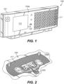
- FIG. 1 an illustrative view of an embodiment of an antenna component in accordance with the disclosure is shown in Fig. 1 and is designated generally by reference character 100.
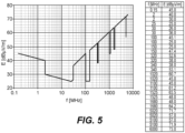
- FIG. 3 An embodiment of a filter component in accordance with the disclosure is shown in Fig. 3 and is designated generally by reference character 300.
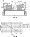
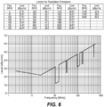
- Other embodiments and/or aspects of this disclosure are shown in Figs. 2 and 4-6 .
- Certain embodiments described herein can be used to enable aircraft inserts with wireless communication.
- an antenna component 100 for an aircraft insert can include a non-conductive body 101 having an outer surface 103a and an inner surface 103b (e.g., the opposite side of the non-conductive body 101 from the outer surface 103a).
- the inner surface 103b can be configured to be hidden from view when installed on the insert.
- the antenna component 100 can include a surface antenna assembly 205 disposed on the inner surface 103b such that when the non-conductive body 101 is installed on the insert, the surface antenna assembly 205 is not visible.
- the surface antenna assembly 205 can be configured (e.g., dimensioned) to receive one or more predetermined frequencies (e.g., frequencies used for WIFI, Bluetooth, RFID, or any other suitable communication frequency).
- the non-conductive body 101 can be configured to pass at least the one or more predetermined frequencies (e.g., by virtue of being non-conductive or otherwise not being an EM shield or filter for the one or more predetermined frequencies).
- the non-conductive body 103b can be plastic, for example. Any other suitable non-conductive material is contemplated herein.
- the surface antenna assembly 205 can include a conductive trace antenna 207 disposed on the inner surface 103b of the non-conductive body 101 and configured to act as an antenna for the one or more predetermined frequencies.
- the conductive trace antenna 207 can include any suitable number of legs (e.g., multiple legs as shown).
- the conductive trace antenna 207 can be printed on to the inner surface 103b for example, or otherwise be manufactured onto the inner surface 103b.
- the conductive trace as disclosed herein can form a very thin layer where placed, approximating a 2-dimensional surface.
- the conductive trace can be a deposited metal layer. Any suitable number of conductive trace antennas 207 of any suitable shapes and/or sizes appreciated by those having ordinary skill in the art to perform the desired function are contemplated herein.
- the surface antenna assembly 205 can include an electrical connector 209 mounted to the inner surface 103b of the non-conductive body 101 in electrical communication with each leg of the conductive trace antenna 107 to provide a connection point for one or more other electrical connectors 209.
- the electrical connector 209 can be a pin connector, e.g., as shown, for example. Any other suitable connection type (e.g., to transmit electrical signals to/from a receiver/transmitter) is contemplated herein.
- the non-conductive body 101 can be a faceplate for an aircraft appliance (e.g., an oven).
- the non-conductive body 101 can define a grill 111 and a window 113 for viewing an electronic display (of the insert).
- the outer surface 103a can include one or more touch buttons 115 for operating the appliance.
- the conductive material can also be used to create capacitive touch buttons, through the non-conductive material. Any other suitable features are contemplated herein.
- the surface antenna assembly 205 can also include a conductive trace filter 217 defined on the inner surface 103b and surrounding one or more conductive trace antennas 207 to provide filtering (e.g., EMI protection), for example (e.g., to block specific frequencies or frequency ranges).
- the conductive trace filter 217 can define a cage or grid shape (e.g., as shown), for example. Any other suitable shapes are contemplated herein (e.g., to provide a faraday cage).
- an aircraft insert can include any suitable embodiment of an antenna component as disclosed herein, e.g., component 100 as described above.
- the aircraft insert can be an oven configured to communicate wirelessly over an aircraft network. Any other suitable aircraft appliance is contemplated herein.
- a filter component 300 for an aircraft insert can include a non-conductive body 301 having an outer surface 303a and an inner surface 303b.
- the inner surface 301b can be configured to be hidden from view when installed on the insert.
- the filter component 300 can include a surface filter 305 disposed on the inner surface 303b such that when the non-conductive body 301 is installed on the insert, the surface filter is not visible 305.
- the surface filter 305 can be configured to filter out one or more predetermined filter frequencies (e.g., one or more frequencies emitted by the insert that interferes with one or more other aircraft electronics).
- the non-conductive body 301 can be plastic, for example. Any other suitable non-conductive material is contemplated herein.
- the surface filter 305 can be or include a conductive trace filter (e.g., as shown) disposed on the inner surface 303b of the non-conductive body 301 and configured to act as frequency filter for the one or more predetermined filter frequencies.
- the conductive trace filter 305 can be printed on to the inner surface 303b for example, or otherwise be manufactured onto the inner surface 303b.
- the conductive trace as disclosed herein can form a very thin layer where placed, approximating a 2-dimensional surface.
- the conductive trace can be a deposited metal layer.
- the non-conductive body 301 is a faceplate for an aircraft appliance (e.g., an oven), for example.
- the non-conductive body 301 defines a grill 307 and a window 309 for viewing an electronic display, for example. Any other suitable features are contemplated herein.
- the conductive trace filter 305 covers a portion of the grill 307 to define an uncovered portion 307a (e.g., as shown) to pass one or more communication frequencies (e.g., at a specific location of the component 300 to allow an antenna of the insert to receive and/or transmit desired frequencies through the uncovered portion 307a).
- there may be no uncovered portion and the conductive trace filter 305 can cover any suitable portion (e.g., the entirety of) the inner surface 303b (e.g., with a suitable shape to permit communication frequencies but block EMI frequencies).
- the conductive trace filter 305 can be formed to conform with one or more inner surface shapes (e.g., the grill 307, for example).
- the conductive trace filter 305 can define a cage or grid shape to act as a faraday cage (e.g., following the shape of a grill 307, or positioned elsewhere e.g., on a flat surface).
- Gaps 305a in the cage or grid shape e.g., and/or holes forming the same shape in the grill 307) can be sized to filter frequencies having wavelengths larger than the gaps 305 a.
- the uncovered portion 307a can be sized and shaped to pass wavelengths equal to or smaller than the diameter or longest dimension of the uncovered portion 307a. Any other suitable shapes and/or filter features are contemplated herein.
- the surface filter 305 can be configured pass one or more predetermined communication frequencies while filtering the one or more predetermined frequencies to aircraft device emissions limits (e.g., as shown in Figs. 4-6 ). Examiner emissions limits are shown in Figs. 4-6 . Any suitable frequencies for filtering (e.g., to be under predetermined magnitude limits for aircraft standards) are contemplated herein.
- an aircraft insert can include any suitable embodiment of a filter component for the aircraft insert disclosed herein, e.g., as component 300 described above.
- the aircraft insert can be an oven configured to communicate wirelessly over an aircraft network. Any other suitable aircraft appliance is contemplated herein.
- Embodiments allow for placing an antenna where it is outside of an EMF shield of the insert, but also without affecting the aesthetics and exposure of the antenna components.
- Embodiments can include an antenna that can be hidden behind a plastic component, e.g., printed on the inside surface.
- Embodiments can have a connector extending from a face for connecting the antenna to a cable for example.
- Embodiments can be applied to any aircraft insert or plastic component thereof, for example, e.g., any suitable front plastic panel of an insert (e.g., replaceable or otherwise).
- the antenna can be integrated into a door of the aircraft insert.
- Embodiments can be combined with EMI shielding features, also reducing the undesired emissions of the insert.
- Embodiments can include integrated or hidden LEDs or other indicators for indicating the status of a wireless connection.
- Embodiments can include printed electronics to create an RF shield to block specific frequencies, for example. Certain embodiments can be configured to block about 200 MHz to about 300 MHz. As appreciated by those having ordinary skill in the art, the shorter the wavelength, the better it passes through a mesh of given size. Thus to work well at short wavelengths (i.e., high frequencies), the holes in a faraday cage must be smaller than the wavelength or a fraction thereof (e.g., a fourth) of the incident wave. Any suitable hole size or pattern is contemplated herein.
- Embodiments can utilize in-mold or printed electronics to integrate an antenna into insert plastic parts, for example, in a removable faceplate/grill of an insert (e.g., an oven). This way it can be installed outside of the insert front but hidden from view.
- Embodiments can include traces on the inside of a plastic part. These traces can also be printed in the form of PCB antennas or EMI shields.
- Embodiments can have an antenna on the absolute front of the insert, not being obstructed by any other component of the insert (such as an HMI).
- the antenna can cover an entire back side the front grill surface, allowing the maximum size possible, for example.
- Embodiments do not affect aesthetics, can be protected from outside tampering, and can improve functionality. Because of the large surface area, embodiments may allow for integrating multiple antennae, for example for different frequency ranges.
- a reference to "A and/or B", when used in conjunction with open-ended language such as “comprising” can refer, in one embodiment, to A only (optionally including elements other than B); in another embodiment, to B only (optionally including elements other than A); in yet another embodiment, to both A and B (optionally including other elements); etc.
Landscapes
- Engineering & Computer Science (AREA)
- Aviation & Aerospace Engineering (AREA)
- Physics & Mathematics (AREA)
- Electromagnetism (AREA)
- Computer Networks & Wireless Communication (AREA)
- Details Of Aerials (AREA)
Claims (12)
- EM-Filterkomponente für einen Flugzeugeinsatz, umfassend:einen nichtleitenden Körper (101, 301) mit einer Außenfläche und einer Innenfläche, wobei die Innenfläche dazu konfiguriert ist, auf dem Einsatz installiert nicht sichtbar zu sein; undeinen Oberflächenfilter (305), der derart auf der Innenfläche angeordnet ist, dass der Oberflächenfilter (305) nicht sichtbar ist, wenn der nichtleitende Körper (101, 301) auf dem Einsatz installiert ist, wobei der Oberflächenfilter (305) dazu konfiguriert ist, eine oder mehrere vorbestimmte Filterfrequenzen herausfiltert, wobei der nichtleitende Körper (101, 301) eine Frontplatte für eine Flugzeugeinrichtung ist und wobei der nichtleitende Körper (101, 301) ein Gitter und ein Fenster zum Betrachten einer elektronischen Anzeige definiert und wobei der Oberflächenfilter einen Teil des Gitters abdeckt, um einen unbedeckten Teil zum Durchlassen einer oder mehrerer Kommunikationsfrequenzen zu definieren.
- Filterkomponente nach Anspruch 1, wobei der nichtleitende Körper (101, 301) aus Kunststoff ist.
- Filterkomponente nach Anspruch 1 oder 2, wobei der Oberflächenfilter (305) einen leitfähigen Trace-Filter umfasst, der auf der Innenfläche des nichtleitenden Körpers (101, 301) angeordnet und dazu konfiguriert ist, als Frequenzfilter für die eine oder mehreren vorbestimmten Filterfrequenzen zu wirken.
- Filterkomponente nach Anspruch 3, wobei der leitfähige Trace-Filter ausbildet ist, um sich an eine oder mehrere Formen der Innenfläche anzupassen.
- Filterkomponente nach Anspruch 3, wobei der leitfähige Trace-Filter eine Käfig- oder Gitterform definiert, um als Faradayscher Käfig zu wirken.
- Filterkomponente nach Anspruch 5, wobei Lücken in der Käfig- oder Gitterform bemessen sind, um Frequenzen mit Wellenlängen zu filtern, die größer sind als die Lücken.
- Filterkomponente nach einem der vorhergehenden Ansprüche, wobei der Oberflächenfilter (305) dazu konfiguriert ist, eine oder mehrere vorbestimmte Kommunikationsfrequenzen durchzulassen, während er die eine oder mehrere vorbestimmten Frequenzen gemäß den Emissionsgrenzwerten für Flugzeugeinrichtungen filtert.
- Flugzeugeinsatz, umfassend:
die EM-Filterkomponente nach einem der vorhergehenden Ansprüche. - Einsatz nach Anspruch 8, wobei der Oberflächenfilter einen leitfähigen Trace-Filter umfasst, der auf der Innenfläche des nichtleitenden Körpers (101, 301) angeordnet und dazu konfiguriert ist, als Frequenzfilter für die eine oder mehreren vorbestimmten Filterfrequenzen zu fungieren.
- Einsatz nach Anspruch 8 oder 9, wobei der leitfähige Trace-Filter geformt ist, um sich an eine oder mehrere Formen der Innenfläche anzupassen, oder wobei der leitfähige Trace-Filter eine Käfig- oder Gitterform definiert, um als Faradayscher Käfig zu wirken.
- Einsatz nach Anspruch 9 oder 10, wobei der Oberflächenfilter (305) dazu konfiguriert ist, eine oder mehrere vorbestimmte Kommunikationsfrequenzen durchzulassen, während er die eine oder mehrere vorbestimmten Frequenzen gemäß den Emissionsgrenzwerten für Flugzeugeinrichtungen filtert.
- Einsatz nach Anspruch 11, wobei der Einsatz ein Ofen ist, der für die drahtlose Kommunikation über ein Flugzeugnetzwerk konfiguriert ist.
Applications Claiming Priority (1)
| Application Number | Priority Date | Filing Date | Title |
|---|---|---|---|
| US17/131,707 US11975838B2 (en) | 2020-12-22 | 2020-12-22 | Aircraft inserts having surface integrated antennas and/or filters |
Publications (2)
| Publication Number | Publication Date |
|---|---|
| EP4019401A1 EP4019401A1 (de) | 2022-06-29 |
| EP4019401B1 true EP4019401B1 (de) | 2024-08-07 |
Family
ID=79021151
Family Applications (1)
| Application Number | Title | Priority Date | Filing Date |
|---|---|---|---|
| EP21217031.0A Active EP4019401B1 (de) | 2020-12-22 | 2021-12-22 | Flugzeugeinsätze mit oberflächenintegrierten antennen und/oder filtern |
Country Status (2)
| Country | Link |
|---|---|
| US (1) | US11975838B2 (de) |
| EP (1) | EP4019401B1 (de) |
Family Cites Families (12)
| Publication number | Priority date | Publication date | Assignee | Title |
|---|---|---|---|---|
| US5982339A (en) * | 1996-11-26 | 1999-11-09 | Ball Aerospace & Technologies Corp. | Antenna system utilizing a frequency selective surface |
| US6855883B1 (en) * | 1997-02-11 | 2005-02-15 | Kazu Investment Co., Ltd. | Electromagnetic wave blocking material and electromagnetic wave blocking case |
| US20080011510A1 (en) * | 2006-07-12 | 2008-01-17 | General Electric Company | Hybrid faceplate having reduced EMI emissions |
| DE102008048500A1 (de) | 2008-09-23 | 2010-04-15 | Airbus Deutschland Gmbh | Verschließbare Einrichtung mit Daten- und Energieübertragung durch elektromagnetische Induktion |
| US20140014436A1 (en) * | 2012-07-12 | 2014-01-16 | B/E Aerospace, Inc. | Noise-Reducing Air Inlet Grille for an Appliance |
| CN102868021B (zh) | 2012-09-27 | 2015-09-09 | 中国科学院长春光学精密机械与物理研究所 | 一种高性能频率选择雷达罩 |
| US9624693B2 (en) | 2015-03-03 | 2017-04-18 | The Boeing Company | Integrated locks with visual indicators for aircraft galley systems |
| US9876280B1 (en) * | 2015-12-07 | 2018-01-23 | Raytheon Company | Radome with radio frequency filtering surface |
| CN205807533U (zh) * | 2016-06-24 | 2016-12-14 | 广东美的厨房电器制造有限公司 | 一种带app模块的微波炉 |
| US10798549B1 (en) | 2019-04-01 | 2020-10-06 | B/E Aerospace, Inc. | Galley insert wireless communication system |
| JP7338567B2 (ja) * | 2020-06-30 | 2023-09-05 | 豊田合成株式会社 | 電磁波透過カバー |
| JPWO2022070916A1 (de) * | 2020-09-29 | 2022-04-07 |
-
2020
- 2020-12-22 US US17/131,707 patent/US11975838B2/en active Active
-
2021
- 2021-12-22 EP EP21217031.0A patent/EP4019401B1/de active Active
Also Published As
| Publication number | Publication date |
|---|---|
| US20220194591A1 (en) | 2022-06-23 |
| US11975838B2 (en) | 2024-05-07 |
| EP4019401A1 (de) | 2022-06-29 |
Similar Documents
| Publication | Publication Date | Title |
|---|---|---|
| WO2008033331A3 (en) | Antenna arrangement for an electronic device and an electronic device including same | |
| CN101814653B (zh) | 具有射频护罩的印刷电路板天线组件 | |
| EP3188571B1 (de) | Gerät mit einer antenne mit verwendung eines teils eines geräts als massefläche | |
| EP4020709B1 (de) | Flugzeugeinsätze mit oberflächenintegrierten antennen und/oder filtern | |
| EP3841926B1 (de) | Funktionselement für ein küchengerät, küchengerät sowie verfahren zur datenkommunikation | |
| WO1997015982A1 (en) | A shielding device | |
| WO2008008693A3 (en) | Hybrid faceplate having reduced emi emissions | |
| US10381722B2 (en) | Tuned grounding arm for near field radio coexistence | |
| US11975838B2 (en) | Aircraft inserts having surface integrated antennas and/or filters | |
| US10199791B2 (en) | Method for connecting two devices and having a fastening device | |
| EP3921656B1 (de) | Mehrfachantennen am messgerätgehäuse | |
| US7932483B2 (en) | Household appliance with an electric control system and an accessory part | |
| EP3163676A1 (de) | Leiterplatte für eine antennenanordnung | |
| US20070216582A1 (en) | Antenna device with ion-implanted antenna pattern | |
| EP3443267B1 (de) | Gargerät mit einer flächenantenne und verfahren zum betreiben eines gargeräts | |
| US20090101494A1 (en) | Method for Producing Internal Antenna with Anti-Electromagnetic Interference Property Through Vacuum Process | |
| CN106516162A (zh) | 电磁超静卫星平台设计方法 | |
| US20040242168A1 (en) | Module for transmitting and/or receiving radio data | |
| CN215011348U (zh) | 一种智能融合终端电磁屏蔽机壳 | |
| EP2987211B1 (de) | Funkfrequenzabschirmung | |
| US11291145B2 (en) | Integrated antenna device | |
| CN209930822U (zh) | 屏蔽装置 | |
| WO2001065903A3 (en) | Methods and apparatus for emi shielding | |
| TR201815458T4 (tr) | Kablosuz elektronik telekomünikasyon cihazı, özellikle cep telefonu. | |
| CN106207452B (zh) | 一种偶极子天线与八木天线复合的组合天线 |
Legal Events
| Date | Code | Title | Description |
|---|---|---|---|
| PUAI | Public reference made under article 153(3) epc to a published international application that has entered the european phase |
Free format text: ORIGINAL CODE: 0009012 |
|
| STAA | Information on the status of an ep patent application or granted ep patent |
Free format text: STATUS: THE APPLICATION HAS BEEN PUBLISHED |
|
| AK | Designated contracting states |
Kind code of ref document: A1 Designated state(s): AL AT BE BG CH CY CZ DE DK EE ES FI FR GB GR HR HU IE IS IT LI LT LU LV MC MK MT NL NO PL PT RO RS SE SI SK SM TR |
|
| STAA | Information on the status of an ep patent application or granted ep patent |
Free format text: STATUS: REQUEST FOR EXAMINATION WAS MADE |
|
| 17P | Request for examination filed |
Effective date: 20221228 |
|
| RBV | Designated contracting states (corrected) |
Designated state(s): AL AT BE BG CH CY CZ DE DK EE ES FI FR GB GR HR HU IE IS IT LI LT LU LV MC MK MT NL NO PL PT RO RS SE SI SK SM TR |
|
| REG | Reference to a national code |
Ref country code: DE Ref legal event code: R079 Free format text: PREVIOUS MAIN CLASS: B64D0011000000 Ipc: H01Q0001520000 Ref country code: DE Ref legal event code: R079 Ref document number: 602021016774 Country of ref document: DE Free format text: PREVIOUS MAIN CLASS: B64D0011000000 Ipc: H01Q0001520000 |
|
| GRAP | Despatch of communication of intention to grant a patent |
Free format text: ORIGINAL CODE: EPIDOSNIGR1 |
|
| STAA | Information on the status of an ep patent application or granted ep patent |
Free format text: STATUS: GRANT OF PATENT IS INTENDED |
|
| RIC1 | Information provided on ipc code assigned before grant |
Ipc: H01Q 15/00 20060101ALN20240131BHEP Ipc: H01Q 1/22 20060101ALI20240131BHEP Ipc: H01Q 1/52 20060101ALI20240131BHEP Ipc: B64D 11/04 20060101ALI20240131BHEP Ipc: B64D 11/00 20060101AFI20240131BHEP |
|
| RIC1 | Information provided on ipc code assigned before grant |
Ipc: B64D 11/04 20060101ALN20240205BHEP Ipc: B64D 11/00 20060101ALN20240205BHEP Ipc: H01Q 15/00 20060101ALN20240205BHEP Ipc: H01Q 1/22 20060101ALI20240205BHEP Ipc: H01Q 1/52 20060101AFI20240205BHEP |
|
| RIC1 | Information provided on ipc code assigned before grant |
Ipc: B64D 11/04 20060101ALN20240212BHEP Ipc: B64D 11/00 20060101ALN20240212BHEP Ipc: H01Q 15/00 20060101ALN20240212BHEP Ipc: H01Q 1/22 20060101ALI20240212BHEP Ipc: H01Q 1/52 20060101AFI20240212BHEP |
|
| INTG | Intention to grant announced |
Effective date: 20240306 |
|
| RAP1 | Party data changed (applicant data changed or rights of an application transferred) |
Owner name: B/E AEROSPACE, INC. |
|
| GRAS | Grant fee paid |
Free format text: ORIGINAL CODE: EPIDOSNIGR3 |
|
| GRAA | (expected) grant |
Free format text: ORIGINAL CODE: 0009210 |
|
| STAA | Information on the status of an ep patent application or granted ep patent |
Free format text: STATUS: THE PATENT HAS BEEN GRANTED |
|
| AK | Designated contracting states |
Kind code of ref document: B1 Designated state(s): AL AT BE BG CH CY CZ DE DK EE ES FI FR GB GR HR HU IE IS IT LI LT LU LV MC MK MT NL NO PL PT RO RS SE SI SK SM TR |
|
| REG | Reference to a national code |
Ref country code: GB Ref legal event code: FG4D |
|
| REG | Reference to a national code |
Ref country code: CH Ref legal event code: EP |
|
| REG | Reference to a national code |
Ref country code: NL Ref legal event code: FP Ref country code: IE Ref legal event code: FG4D |
|
| REG | Reference to a national code |
Ref country code: DE Ref legal event code: R096 Ref document number: 602021016774 Country of ref document: DE |
|
| REG | Reference to a national code |
Ref country code: LT Ref legal event code: MG9D |
|
| PG25 | Lapsed in a contracting state [announced via postgrant information from national office to epo] |
Ref country code: NO Free format text: LAPSE BECAUSE OF FAILURE TO SUBMIT A TRANSLATION OF THE DESCRIPTION OR TO PAY THE FEE WITHIN THE PRESCRIBED TIME-LIMIT Effective date: 20241107 |
|
| REG | Reference to a national code |
Ref country code: AT Ref legal event code: MK05 Ref document number: 1711984 Country of ref document: AT Kind code of ref document: T Effective date: 20240807 |
|
| PG25 | Lapsed in a contracting state [announced via postgrant information from national office to epo] |
Ref country code: GR Free format text: LAPSE BECAUSE OF FAILURE TO SUBMIT A TRANSLATION OF THE DESCRIPTION OR TO PAY THE FEE WITHIN THE PRESCRIBED TIME-LIMIT Effective date: 20241108 Ref country code: PL Free format text: LAPSE BECAUSE OF FAILURE TO SUBMIT A TRANSLATION OF THE DESCRIPTION OR TO PAY THE FEE WITHIN THE PRESCRIBED TIME-LIMIT Effective date: 20240807 Ref country code: PT Free format text: LAPSE BECAUSE OF FAILURE TO SUBMIT A TRANSLATION OF THE DESCRIPTION OR TO PAY THE FEE WITHIN THE PRESCRIBED TIME-LIMIT Effective date: 20241209 Ref country code: FI Free format text: LAPSE BECAUSE OF FAILURE TO SUBMIT A TRANSLATION OF THE DESCRIPTION OR TO PAY THE FEE WITHIN THE PRESCRIBED TIME-LIMIT Effective date: 20240807 |
|
| PG25 | Lapsed in a contracting state [announced via postgrant information from national office to epo] |
Ref country code: BG Free format text: LAPSE BECAUSE OF FAILURE TO SUBMIT A TRANSLATION OF THE DESCRIPTION OR TO PAY THE FEE WITHIN THE PRESCRIBED TIME-LIMIT Effective date: 20240807 |
|
| PG25 | Lapsed in a contracting state [announced via postgrant information from national office to epo] |
Ref country code: LV Free format text: LAPSE BECAUSE OF FAILURE TO SUBMIT A TRANSLATION OF THE DESCRIPTION OR TO PAY THE FEE WITHIN THE PRESCRIBED TIME-LIMIT Effective date: 20240807 |
|
| PG25 | Lapsed in a contracting state [announced via postgrant information from national office to epo] |
Ref country code: AT Free format text: LAPSE BECAUSE OF FAILURE TO SUBMIT A TRANSLATION OF THE DESCRIPTION OR TO PAY THE FEE WITHIN THE PRESCRIBED TIME-LIMIT Effective date: 20240807 Ref country code: IS Free format text: LAPSE BECAUSE OF FAILURE TO SUBMIT A TRANSLATION OF THE DESCRIPTION OR TO PAY THE FEE WITHIN THE PRESCRIBED TIME-LIMIT Effective date: 20241207 |
|
| PG25 | Lapsed in a contracting state [announced via postgrant information from national office to epo] |
Ref country code: HR Free format text: LAPSE BECAUSE OF FAILURE TO SUBMIT A TRANSLATION OF THE DESCRIPTION OR TO PAY THE FEE WITHIN THE PRESCRIBED TIME-LIMIT Effective date: 20240807 |
|
| PG25 | Lapsed in a contracting state [announced via postgrant information from national office to epo] |
Ref country code: RS Free format text: LAPSE BECAUSE OF FAILURE TO SUBMIT A TRANSLATION OF THE DESCRIPTION OR TO PAY THE FEE WITHIN THE PRESCRIBED TIME-LIMIT Effective date: 20241107 Ref country code: ES Free format text: LAPSE BECAUSE OF FAILURE TO SUBMIT A TRANSLATION OF THE DESCRIPTION OR TO PAY THE FEE WITHIN THE PRESCRIBED TIME-LIMIT Effective date: 20240807 |
|
| PG25 | Lapsed in a contracting state [announced via postgrant information from national office to epo] |
Ref country code: RS Free format text: LAPSE BECAUSE OF FAILURE TO SUBMIT A TRANSLATION OF THE DESCRIPTION OR TO PAY THE FEE WITHIN THE PRESCRIBED TIME-LIMIT Effective date: 20241107 Ref country code: PT Free format text: LAPSE BECAUSE OF FAILURE TO SUBMIT A TRANSLATION OF THE DESCRIPTION OR TO PAY THE FEE WITHIN THE PRESCRIBED TIME-LIMIT Effective date: 20241209 Ref country code: PL Free format text: LAPSE BECAUSE OF FAILURE TO SUBMIT A TRANSLATION OF THE DESCRIPTION OR TO PAY THE FEE WITHIN THE PRESCRIBED TIME-LIMIT Effective date: 20240807 Ref country code: NO Free format text: LAPSE BECAUSE OF FAILURE TO SUBMIT A TRANSLATION OF THE DESCRIPTION OR TO PAY THE FEE WITHIN THE PRESCRIBED TIME-LIMIT Effective date: 20241107 Ref country code: LV Free format text: LAPSE BECAUSE OF FAILURE TO SUBMIT A TRANSLATION OF THE DESCRIPTION OR TO PAY THE FEE WITHIN THE PRESCRIBED TIME-LIMIT Effective date: 20240807 Ref country code: IS Free format text: LAPSE BECAUSE OF FAILURE TO SUBMIT A TRANSLATION OF THE DESCRIPTION OR TO PAY THE FEE WITHIN THE PRESCRIBED TIME-LIMIT Effective date: 20241207 Ref country code: HR Free format text: LAPSE BECAUSE OF FAILURE TO SUBMIT A TRANSLATION OF THE DESCRIPTION OR TO PAY THE FEE WITHIN THE PRESCRIBED TIME-LIMIT Effective date: 20240807 Ref country code: GR Free format text: LAPSE BECAUSE OF FAILURE TO SUBMIT A TRANSLATION OF THE DESCRIPTION OR TO PAY THE FEE WITHIN THE PRESCRIBED TIME-LIMIT Effective date: 20241108 Ref country code: FI Free format text: LAPSE BECAUSE OF FAILURE TO SUBMIT A TRANSLATION OF THE DESCRIPTION OR TO PAY THE FEE WITHIN THE PRESCRIBED TIME-LIMIT Effective date: 20240807 Ref country code: ES Free format text: LAPSE BECAUSE OF FAILURE TO SUBMIT A TRANSLATION OF THE DESCRIPTION OR TO PAY THE FEE WITHIN THE PRESCRIBED TIME-LIMIT Effective date: 20240807 Ref country code: BG Free format text: LAPSE BECAUSE OF FAILURE TO SUBMIT A TRANSLATION OF THE DESCRIPTION OR TO PAY THE FEE WITHIN THE PRESCRIBED TIME-LIMIT Effective date: 20240807 Ref country code: AT Free format text: LAPSE BECAUSE OF FAILURE TO SUBMIT A TRANSLATION OF THE DESCRIPTION OR TO PAY THE FEE WITHIN THE PRESCRIBED TIME-LIMIT Effective date: 20240807 |
|
| PG25 | Lapsed in a contracting state [announced via postgrant information from national office to epo] |
Ref country code: SM Free format text: LAPSE BECAUSE OF FAILURE TO SUBMIT A TRANSLATION OF THE DESCRIPTION OR TO PAY THE FEE WITHIN THE PRESCRIBED TIME-LIMIT Effective date: 20240807 Ref country code: DK Free format text: LAPSE BECAUSE OF FAILURE TO SUBMIT A TRANSLATION OF THE DESCRIPTION OR TO PAY THE FEE WITHIN THE PRESCRIBED TIME-LIMIT Effective date: 20240807 |
|
| PG25 | Lapsed in a contracting state [announced via postgrant information from national office to epo] |
Ref country code: EE Free format text: LAPSE BECAUSE OF FAILURE TO SUBMIT A TRANSLATION OF THE DESCRIPTION OR TO PAY THE FEE WITHIN THE PRESCRIBED TIME-LIMIT Effective date: 20240807 |
|
| PG25 | Lapsed in a contracting state [announced via postgrant information from national office to epo] |
Ref country code: CZ Free format text: LAPSE BECAUSE OF FAILURE TO SUBMIT A TRANSLATION OF THE DESCRIPTION OR TO PAY THE FEE WITHIN THE PRESCRIBED TIME-LIMIT Effective date: 20240807 |
|
| PG25 | Lapsed in a contracting state [announced via postgrant information from national office to epo] |
Ref country code: SK Free format text: LAPSE BECAUSE OF FAILURE TO SUBMIT A TRANSLATION OF THE DESCRIPTION OR TO PAY THE FEE WITHIN THE PRESCRIBED TIME-LIMIT Effective date: 20240807 |
|
| REG | Reference to a national code |
Ref country code: DE Ref legal event code: R097 Ref document number: 602021016774 Country of ref document: DE |
|
| PLBE | No opposition filed within time limit |
Free format text: ORIGINAL CODE: 0009261 |
|
| STAA | Information on the status of an ep patent application or granted ep patent |
Free format text: STATUS: NO OPPOSITION FILED WITHIN TIME LIMIT |
|
| PG25 | Lapsed in a contracting state [announced via postgrant information from national office to epo] |
Ref country code: MC Free format text: LAPSE BECAUSE OF FAILURE TO SUBMIT A TRANSLATION OF THE DESCRIPTION OR TO PAY THE FEE WITHIN THE PRESCRIBED TIME-LIMIT Effective date: 20240807 |
|
| 26N | No opposition filed |
Effective date: 20250508 |
|
| REG | Reference to a national code |
Ref country code: CH Ref legal event code: PL |
|
| PG25 | Lapsed in a contracting state [announced via postgrant information from national office to epo] |
Ref country code: LU Free format text: LAPSE BECAUSE OF NON-PAYMENT OF DUE FEES Effective date: 20241222 |
|
| PG25 | Lapsed in a contracting state [announced via postgrant information from national office to epo] |
Ref country code: SE Free format text: LAPSE BECAUSE OF FAILURE TO SUBMIT A TRANSLATION OF THE DESCRIPTION OR TO PAY THE FEE WITHIN THE PRESCRIBED TIME-LIMIT Effective date: 20240807 |
|
| REG | Reference to a national code |
Ref country code: BE Ref legal event code: MM Effective date: 20241231 |
|
| PG25 | Lapsed in a contracting state [announced via postgrant information from national office to epo] |
Ref country code: BE Free format text: LAPSE BECAUSE OF NON-PAYMENT OF DUE FEES Effective date: 20241231 |
|
| PG25 | Lapsed in a contracting state [announced via postgrant information from national office to epo] |
Ref country code: CH Free format text: LAPSE BECAUSE OF NON-PAYMENT OF DUE FEES Effective date: 20241231 |
|
| PG25 | Lapsed in a contracting state [announced via postgrant information from national office to epo] |
Ref country code: IE Free format text: LAPSE BECAUSE OF NON-PAYMENT OF DUE FEES Effective date: 20241222 |
|
| PG25 | Lapsed in a contracting state [announced via postgrant information from national office to epo] |
Ref country code: RO Free format text: LAPSE BECAUSE OF FAILURE TO SUBMIT A TRANSLATION OF THE DESCRIPTION OR TO PAY THE FEE WITHIN THE PRESCRIBED TIME-LIMIT Effective date: 20240807 |
|
| PGFP | Annual fee paid to national office [announced via postgrant information from national office to epo] |
Ref country code: NL Payment date: 20251119 Year of fee payment: 5 |
|
| PGFP | Annual fee paid to national office [announced via postgrant information from national office to epo] |
Ref country code: DE Payment date: 20251126 Year of fee payment: 5 |
|
| PGFP | Annual fee paid to national office [announced via postgrant information from national office to epo] |
Ref country code: GB Payment date: 20251119 Year of fee payment: 5 |
|
| PGFP | Annual fee paid to national office [announced via postgrant information from national office to epo] |
Ref country code: FR Payment date: 20251120 Year of fee payment: 5 |
|
| PG25 | Lapsed in a contracting state [announced via postgrant information from national office to epo] |
Ref country code: IT Free format text: LAPSE BECAUSE OF FAILURE TO SUBMIT A TRANSLATION OF THE DESCRIPTION OR TO PAY THE FEE WITHIN THE PRESCRIBED TIME-LIMIT Effective date: 20240807 |
|
| PG25 | Lapsed in a contracting state [announced via postgrant information from national office to epo] |
Ref country code: CY Free format text: LAPSE BECAUSE OF FAILURE TO SUBMIT A TRANSLATION OF THE DESCRIPTION OR TO PAY THE FEE WITHIN THE PRESCRIBED TIME-LIMIT Effective date: 20240807 |
|
| PG25 | Lapsed in a contracting state [announced via postgrant information from national office to epo] |
Ref country code: TR Free format text: LAPSE BECAUSE OF FAILURE TO SUBMIT A TRANSLATION OF THE DESCRIPTION OR TO PAY THE FEE WITHIN THE PRESCRIBED TIME-LIMIT Effective date: 20240807 |
|
| PG25 | Lapsed in a contracting state [announced via postgrant information from national office to epo] |
Ref country code: HU Free format text: LAPSE BECAUSE OF FAILURE TO SUBMIT A TRANSLATION OF THE DESCRIPTION OR TO PAY THE FEE WITHIN THE PRESCRIBED TIME-LIMIT; INVALID AB INITIO Effective date: 20211222 |
|
| PG25 | Lapsed in a contracting state [announced via postgrant information from national office to epo] |
Ref country code: SI Free format text: LAPSE BECAUSE OF FAILURE TO SUBMIT A TRANSLATION OF THE DESCRIPTION OR TO PAY THE FEE WITHIN THE PRESCRIBED TIME-LIMIT Effective date: 20240807 |
|
| PG25 | Lapsed in a contracting state [announced via postgrant information from national office to epo] |
Ref country code: LT Free format text: LAPSE BECAUSE OF FAILURE TO SUBMIT A TRANSLATION OF THE DESCRIPTION OR TO PAY THE FEE WITHIN THE PRESCRIBED TIME-LIMIT Effective date: 20240807 |