EP4019130B1 - Tür für ein laborautomatisierungsgerät - Google Patents
Tür für ein laborautomatisierungsgerät Download PDFInfo
- Publication number
- EP4019130B1 EP4019130B1 EP20216944.7A EP20216944A EP4019130B1 EP 4019130 B1 EP4019130 B1 EP 4019130B1 EP 20216944 A EP20216944 A EP 20216944A EP 4019130 B1 EP4019130 B1 EP 4019130B1
- Authority
- EP
- European Patent Office
- Prior art keywords
- door
- working area
- processing unit
- work surface
- loading
- Prior art date
- Legal status (The legal status is an assumption and is not a legal conclusion. Google has not performed a legal analysis and makes no representation as to the accuracy of the status listed.)
- Active
Links
Images


Classifications
-
- E—FIXED CONSTRUCTIONS
- E06—DOORS, WINDOWS, SHUTTERS, OR ROLLER BLINDS IN GENERAL; LADDERS
- E06B—FIXED OR MOVABLE CLOSURES FOR OPENINGS IN BUILDINGS, VEHICLES, FENCES OR LIKE ENCLOSURES IN GENERAL, e.g. DOORS, WINDOWS, BLINDS, GATES
- E06B3/00—Window sashes, door leaves, or like elements for closing wall or like openings; Layout of fixed or moving closures, e.g. windows in wall or like openings; Features of rigidly-mounted outer frames relating to the mounting of wing frames
- E06B3/32—Arrangements of wings characterised by the manner of movement; Arrangements of movable wings in openings; Features of wings or frames relating solely to the manner of movement of the wing
- E06B3/34—Arrangements of wings characterised by the manner of movement; Arrangements of movable wings in openings; Features of wings or frames relating solely to the manner of movement of the wing with only one kind of movement
- E06B3/42—Sliding wings; Details of frames with respect to guiding
- E06B3/44—Vertically-sliding wings
-
- B—PERFORMING OPERATIONS; TRANSPORTING
- B01—PHYSICAL OR CHEMICAL PROCESSES OR APPARATUS IN GENERAL
- B01L—CHEMICAL OR PHYSICAL LABORATORY APPARATUS FOR GENERAL USE
- B01L1/00—Enclosures; Chambers
- B01L1/50—Enclosures; Chambers for storing hazardous materials in the laboratory, e.g. cupboards, waste containers
-
- B—PERFORMING OPERATIONS; TRANSPORTING
- B01—PHYSICAL OR CHEMICAL PROCESSES OR APPARATUS IN GENERAL
- B01L—CHEMICAL OR PHYSICAL LABORATORY APPARATUS FOR GENERAL USE
- B01L1/00—Enclosures; Chambers
-
- B—PERFORMING OPERATIONS; TRANSPORTING
- B08—CLEANING
- B08B—CLEANING IN GENERAL; PREVENTION OF FOULING IN GENERAL
- B08B15/00—Preventing escape of dirt or fumes from the area where they are produced; Collecting or removing dirt or fumes from that area
- B08B15/02—Preventing escape of dirt or fumes from the area where they are produced; Collecting or removing dirt or fumes from that area using chambers or hoods covering the area
- B08B15/023—Fume cabinets or cupboards, e.g. for laboratories
-
- B—PERFORMING OPERATIONS; TRANSPORTING
- B25—HAND TOOLS; PORTABLE POWER-DRIVEN TOOLS; MANIPULATORS
- B25J—MANIPULATORS; CHAMBERS PROVIDED WITH MANIPULATION DEVICES
- B25J21/00—Chambers provided with manipulation devices
-
- E—FIXED CONSTRUCTIONS
- E05—LOCKS; KEYS; WINDOW OR DOOR FITTINGS; SAFES
- E05B—LOCKS; ACCESSORIES THEREFOR; HANDCUFFS
- E05B17/00—Accessories in connection with locks
- E05B17/22—Means for operating or controlling lock or fastening device accessories, i.e. other than the fastening members, e.g. switches, indicators
-
- E—FIXED CONSTRUCTIONS
- E05—LOCKS; KEYS; WINDOW OR DOOR FITTINGS; SAFES
- E05B—LOCKS; ACCESSORIES THEREFOR; HANDCUFFS
- E05B65/00—Locks or fastenings for special use
-
- E—FIXED CONSTRUCTIONS
- E06—DOORS, WINDOWS, SHUTTERS, OR ROLLER BLINDS IN GENERAL; LADDERS
- E06B—FIXED OR MOVABLE CLOSURES FOR OPENINGS IN BUILDINGS, VEHICLES, FENCES OR LIKE ENCLOSURES IN GENERAL, e.g. DOORS, WINDOWS, BLINDS, GATES
- E06B3/00—Window sashes, door leaves, or like elements for closing wall or like openings; Layout of fixed or moving closures, e.g. windows in wall or like openings; Features of rigidly-mounted outer frames relating to the mounting of wing frames
- E06B3/32—Arrangements of wings characterised by the manner of movement; Arrangements of movable wings in openings; Features of wings or frames relating solely to the manner of movement of the wing
- E06B3/34—Arrangements of wings characterised by the manner of movement; Arrangements of movable wings in openings; Features of wings or frames relating solely to the manner of movement of the wing with only one kind of movement
- E06B3/42—Sliding wings; Details of frames with respect to guiding
- E06B3/44—Vertically-sliding wings
- E06B3/4407—Single-hung, i.e. having a single vertical sliding panel
-
- E—FIXED CONSTRUCTIONS
- E06—DOORS, WINDOWS, SHUTTERS, OR ROLLER BLINDS IN GENERAL; LADDERS
- E06B—FIXED OR MOVABLE CLOSURES FOR OPENINGS IN BUILDINGS, VEHICLES, FENCES OR LIKE ENCLOSURES IN GENERAL, e.g. DOORS, WINDOWS, BLINDS, GATES
- E06B3/00—Window sashes, door leaves, or like elements for closing wall or like openings; Layout of fixed or moving closures, e.g. windows in wall or like openings; Features of rigidly-mounted outer frames relating to the mounting of wing frames
- E06B3/32—Arrangements of wings characterised by the manner of movement; Arrangements of movable wings in openings; Features of wings or frames relating solely to the manner of movement of the wing
- E06B3/34—Arrangements of wings characterised by the manner of movement; Arrangements of movable wings in openings; Features of wings or frames relating solely to the manner of movement of the wing with only one kind of movement
- E06B3/42—Sliding wings; Details of frames with respect to guiding
- E06B3/44—Vertically-sliding wings
- E06B3/4415—Double-hung, i.e. with two vertical sliding panels
-
- E—FIXED CONSTRUCTIONS
- E06—DOORS, WINDOWS, SHUTTERS, OR ROLLER BLINDS IN GENERAL; LADDERS
- E06B—FIXED OR MOVABLE CLOSURES FOR OPENINGS IN BUILDINGS, VEHICLES, FENCES OR LIKE ENCLOSURES IN GENERAL, e.g. DOORS, WINDOWS, BLINDS, GATES
- E06B5/00—Doors, windows, or like closures for special purposes; Border constructions therefor
-
- G—PHYSICS
- G01—MEASURING; TESTING
- G01N—INVESTIGATING OR ANALYSING MATERIALS BY DETERMINING THEIR CHEMICAL OR PHYSICAL PROPERTIES
- G01N35/00—Automatic analysis not limited to methods or materials provided for in any single one of groups G01N1/00 - G01N33/00; Handling materials therefor
-
- B—PERFORMING OPERATIONS; TRANSPORTING
- B01—PHYSICAL OR CHEMICAL PROCESSES OR APPARATUS IN GENERAL
- B01L—CHEMICAL OR PHYSICAL LABORATORY APPARATUS FOR GENERAL USE
- B01L2200/00—Solutions for specific problems relating to chemical or physical laboratory apparatus
- B01L2200/02—Adapting objects or devices to another
- B01L2200/021—Adjust spacings in an array of wells, pipettes or holders, format transfer between arrays of different size or geometry
- B01L2200/022—Variable spacings
-
- B—PERFORMING OPERATIONS; TRANSPORTING
- B01—PHYSICAL OR CHEMICAL PROCESSES OR APPARATUS IN GENERAL
- B01L—CHEMICAL OR PHYSICAL LABORATORY APPARATUS FOR GENERAL USE
- B01L2200/00—Solutions for specific problems relating to chemical or physical laboratory apparatus
- B01L2200/08—Ergonomic or safety aspects of handling devices
- B01L2200/082—Handling hazardous material
-
- B—PERFORMING OPERATIONS; TRANSPORTING
- B01—PHYSICAL OR CHEMICAL PROCESSES OR APPARATUS IN GENERAL
- B01L—CHEMICAL OR PHYSICAL LABORATORY APPARATUS FOR GENERAL USE
- B01L2200/00—Solutions for specific problems relating to chemical or physical laboratory apparatus
- B01L2200/08—Ergonomic or safety aspects of handling devices
- B01L2200/085—Protection against injuring the user
-
- B—PERFORMING OPERATIONS; TRANSPORTING
- B01—PHYSICAL OR CHEMICAL PROCESSES OR APPARATUS IN GENERAL
- B01L—CHEMICAL OR PHYSICAL LABORATORY APPARATUS FOR GENERAL USE
- B01L2200/00—Solutions for specific problems relating to chemical or physical laboratory apparatus
- B01L2200/08—Ergonomic or safety aspects of handling devices
- B01L2200/087—Ergonomic aspects
-
- E—FIXED CONSTRUCTIONS
- E05—LOCKS; KEYS; WINDOW OR DOOR FITTINGS; SAFES
- E05B—LOCKS; ACCESSORIES THEREFOR; HANDCUFFS
- E05B47/00—Operating or controlling locks or other fastening devices by electric or magnetic means
- E05B2047/0048—Circuits, feeding, monitoring
- E05B2047/0067—Monitoring
-
- G—PHYSICS
- G01—MEASURING; TESTING
- G01N—INVESTIGATING OR ANALYSING MATERIALS BY DETERMINING THEIR CHEMICAL OR PHYSICAL PROPERTIES
- G01N35/00—Automatic analysis not limited to methods or materials provided for in any single one of groups G01N1/00 - G01N33/00; Handling materials therefor
- G01N2035/00178—Special arrangements of analysers
- G01N2035/00306—Housings, cabinets, control panels (details)
- G01N2035/00316—Detecting door closure
Definitions
- the current invention relates to a door for a laboratory workstation.
- Said laboratory workstation comprises a horizontally extending work surface for providing a working area thereon.
- the door is configured to be movable in relation to the work surface between a safety position, in which the door closes the working area for manual access of a user, and an access position in which the working area is open for manual access of a user.
- the invention further relates to a laboratory workstation and a method of controlling a manual access to a workstation of a laboratory workstation.
- Automating of laboratory processes for example for increasing throughput and reducing mistakes, is widely known in the art.
- Several basic laboratory processes are possible to be carried out in an automated manner on distinct devices, named herein laboratory workstations.
- Automated laboratory processes involve for example the transport and/or sorting of laboratory equipment such as laboratory tubes, basins, and/or container for receiving or handling liquids, but may involve also liquid handling processes such as aspirating and/or dispensing liquids, or other operations related to the handling of liquids which for example require the use of additional devices, such as heating or cooling devices, mixing devices, etc.
- the goods required for a desired process are ideally provided before the begin of the process, to allow the process being carried out undisturbed.
- the provision and/or configuration of the goods, such as laboratory equipment, is often carried out manually by a user.
- the automated processes typically involve the application of robotic systems, for example robotic arms for moving items, or pipetting heads for handling fluids or liquids, special care must be taken to secure that no undesired interaction of a user with a robotic system takes places while a robotic item is operating, to protect the user and to ensure that the automated process remains undisturbed.
- a protection screen is known.
- Such a protection screen separates a working area of the laboratory workstation, where the robotic items are operating, from interferences by a user. The screen may be removed when the automation process is completed.
- such screens are configured as doors, which are movable up and down for closing and opening.
- DE102013008019A1 and DE8115894U1 each disclose a laboratory safety workbench with a door having an access opening allowing manual access to a user.
- the door comprises an access opening which is configured for being reversibly changeable between an open status or a closed status, for allowing or restricting a limited, manual access of a user to the working area.
- the access opening In the safety position, the access opening is in the closed status by being positioned by the door below the work surface.
- the position of the door is under the control of the processing unit.
- Said processing unit is further configured to control one or more automated process operations in the working area or parts thereof in dependence of the position of the door.
- a door according to the present invention is particularly suitable for being used in laboratory workstations, such as liquid handling devices, in which robotic devices carry out distinct processes in an automated manner, as the processing of liquids may make it necessary to occasionally load or reload the liquid handling workstation with samples, reagents or other equipment.
- the door according to the present invention may however be further suitable for being used with other devices which involve an automated movement of devices with an occasional need to reach into the device although such devices shall preferably continue to move. In all these cases, the door may provide the possibility to indeed reach into the device without the need to fully stop an automated process while ensuring the safety of a user who must operate the device.
- the door In the access position, the door is moved away in a manner that the working area, and correspondingly the work surface, is open on the user side, so that a user may have access to essentially the full work surface.
- the door is movable into a loading position for allowing a limited access.
- a process operation is in the present context a step or a plurality of steps or operations of a defined working process.
- the present invention particularly refers to a door for devices, on which such working processes may be carried out in a partial or fully automated manner.
- Possible processes which may be carried out automatically are for example the repositioning of laboratory articles or a pipetting of a liquid.
- Pipetting of a liquid includes for example the aspiration and the dispense of a liquid, as well as a mixing process, which is a repeated aspiration and dispensation.
- the repositioning may include for example moving of one or more robotic arms.
- Each process may often be subdivided into distinct substeps or process operations, respectively.
- Complex process operations are then for example distinct process steps which are linked together in a specific order to a desired longer process.
- Complex process operations are for example the execution of dilution series, the execution of assays such as ELISAs (Enzyme-Linked Immunosorbent Assays), or the purification of nucleic acids such as DNA, using for example magnetic bead separation or solid phase extraction.
- One or more process operations may be under the control of a processing unit.
- a processing unit which may also be named herein processor or controller, may control such one or more process operations according to previously deposited commands.
- Such commands may for example be deposited in the form of a software program based on which the processing unit controls the laboratory workstation and/or functionally connected devices and/or robotic devices.
- robotic devices are for example robotic arms comprising one or more gripper, and/or pipetting heads.
- Devices which are connected with the laboratory workstation may be for example an incubator, a mixing device, a stacking device for laboratory articles, a centrifuge, and the like.
- the processing unit is functionally connected to the laboratory workstation for which the door according to the invention is adapted.
- a processing unit typically controls for example a pipetting robot, the liquid to be used, steps of aspirating, dispensing and/or mixing, or other pipetting steps of a pipetting head, and/or may also control one or more function of other connected devices or robotic devices.
- the status of the door is under the control of a processing unit.
- the processing unit may be the processing unit of an associated device, such as a laboratory workstation.
- the door may be functionally connected to its own processing unit which controls the position of the door.
- the processing unit of the door may be functionally connected to the processing unit of the associated device, e.g. of a laboratory workstation.
- a processing unit in the sense of the present invention may be an internal or an external processor.
- An internal processor is for example an integrated processor, while an external processor may for example be the processor of a personal computer or another functionally connected device.
- a laboratory article may for example be a vessel for handling a sample.
- Such vessels are for example tubes made of glass or plastic and may be configured for receiving different volume sizes.
- tubes for handling smaller volumes of a sample may be plastic tubes suitable for taking up small volumes of a liquid such as 10 ⁇ l, or up to 1500 ⁇ l, or tubes for larger volumes of a liquid up to 50 ml or 100ml liquid.
- Vessels for taking up larger volumes of liquids, for example wash solutions or buffer are referred to as container.
- microplates in which a multitude of sample vessels (so-called wells) are summarized on a standardized platform, and for the automation of high throughput processes, the samples are arranged in a high density on the platform.
- microplates used in automation are for example 96 well plates, 384 well plates or 1536 well plates, using which a high number of samples may be systematically examined.
- microplates are mainly sold in a standardized form (e.g. the ANSI SLAS_1-4 2004 standard; American National Standards Institute, 2006).
- the standard concerns on the one hand the type of array and the center distance of the wells as well as the base area of the microplate, the so-called footprint, which is essentially the same for all plate types.
- a pipette tip or a storage box for pipette tips, which may be places onto a pipette of a pipetting head.
- Such pipette tips are arranged in a corresponding storage box in a standardized array adapted to the array of the pipettes of the pipetting head for easier automation.
- Such pipette tips are for example disposable pipette tips or so-called fixed pipette tips.
- a work surface according to the present invention is an essentially horizontally extending surface which is suitable to have for example carrier or laboratory articles such as tubes or microplates to be placed on.
- the term work surface here refers to the two-dimensional, flat surface for placing articles or devices thereon, while the term working area refers to the three-dimensional space above the work surface in which for examples movement sequences as part of a process operation take place. Such movements may for example be carried out by a robotic device such as a robotic arm with a gripper, or a pipetting head, but also movements of a user when for example equipping the work surface in preparation of a desired automated process operation.
- a work surface and/or a corresponding working area thereon is accessible by a user from one side, namely from the side where the user is standing in front of the laboratory workstation.
- a door By the use of a door, such an access side of a work surface for a user may be controlled. It may be suitable to provide additional protection on those sides of the work surface and the working area, which are typically not foreseen to be manually accessible by a user.
- the laboratory workstation may further comprise a robotic device.
- a typical robotic device is for example a robotic arm comprising a gripper, with which equipment on the work surface may be moved in a targeted manner in the working area, for example for repositioning on the work surface.
- Another typical robotic device is for example a pipetting head.
- On a pipetting head one or more automatically operated pipettes are arranged.
- a distinction may be made between a single-channel pipetting head which comprises one single pipette, and a multichannel pipetting head which may comprise for example 8 pipettes or more.
- the use of a multichannel pipetting head comprising for example 96 pipettes is well known.
- the pipettes of a multichannel pipetting head are arranged at a distance from each other equal to the well axis distance of a standard microplate.
- An access opening according to the present invention is an opening in the door which allows e.g. a user to reach through the door from outside into the associated device.
- an access opening is a continuously open through opening through the door.
- the shape and dimension of the access opening may be adapted to the area behind the door which shall be accessed.
- the access opening may be of a rectangular shape, a circular shape or other suitable shapes.
- Restricting a process may still allow an operation to be carried out, but under well-defined conditions and reduced to a minimum extend, while the inhibition is the total stop of any operation to be carried out.
- restriction may describe here that specific operations may be executed by a robotic device, while it is deposited in the software, in which working areas the operations may be carried out.
- the sensor directly monitors the position of the door, as mentioned above and that a functional connection to the locking mechanism and preferably to the processing unit allows the recognition of the position of the door and a signaling of the sensor to the processing unit to for example activate the locking mechanism changing its state.
- the processing unit may activate the locking mechanism to change into a closed state, thereby locking the door in the safety position.
- the processing unit may recognize when the door is moved into one of the working positions, for example requiring an input of a user, using a communication with one or more sensors, using a communication with one or more locking mechanism, or a combination thereof.
- the door may be a rotating door or a flap door.
- a sensor may be configured to monitor continuously the position of the door, and/or the processing unit may be configured to continuously control the signals of the sensor, or to control the sensor at predefined time points or in connection with predefined process operations.
- the door is indeed locked at a defined position, which includes the door being fixed at that position.
- the door may be locked at a position which includes merely blocking the door at the defined position, with the blocking for example allowing the door being movable in a direction which is from a safety aspect acceptable, while blocking a movement into a direction which shall be prohibited.
- the term locking includes both, locking and blocking.
- the senor is configured to monitor the position of the door by monitoring the status of the associated locking mechanism. For example, the sensor may monitor whether the locking mechanism of the door at the safety position is in a closed status and concludes thereof that the door is in the safety position and locked there. In case that the sensor recognizes the locking mechanism at the safety position being in an open status, the sensor may be configured to conclude that the door is not in the safety position. This may for example be provided in particularly robust locking mechanism, which may not easily be overcome by a user unintentionally.
- a locking mechanism is functionally connected for example to two separate sensors, one sensor monitoring the status of the locking mechanism as explained above, and one sensor monitoring the position of the door. This may particularly be desired for example at the safety position, for not only locking the door in the safety position but to further allow the control whether the door is indeed kept in the safety position.
- the locking mechanism is selected from a group comprising a mechanical locking system, an electrical locking system, and a magnetic locking system, or a combination thereof.
- a locking mechanism is comprised of two parts, with one part located on the door, and the other part located on the device onto which the door is mounted. The interaction of the two parts for locking is only possible when the door is in the desired position. It may therefore be provided that the door comprises for each position (safety position, loading position, access position) a separate locking mechanism. Alternatively, it may be provided for example that the same locking mechanism is used for two or more positions, of that an individual locking mechanism is used for a specific position.
- the processing unit recognizes the position of the bolt for example by a sensor coupled to the bolt or a corresponding driving mechanism.
- the end stop may be configured being movable in relation to the bolt, for engaging the bolt when the door shall be locked in a defined position. In this case it may be possible analogously that the movability of the end stop is under the control of the processing unit.
- a suitable locking mechanism may be based on a ball spring which counteracts with a complementary depression.
- the ball spring may be located on the door while the complementary depression is located on the laboratory workstation, or vice versa.
- the ball spring may engage into the complementary depression for locking only when the door is moved into a defined position in relation to the laboratory workstation.
- the ball spring may be moved out of the depression by the user by using a force, or for example under the control of the processing unit.
- the laboratory workstation comprises a loading area on the work surface which is manually accessible by a user through the access opening when the access opening is in the loading status.
- the loading area comprises at least one carrier which is movably mounted on the work surface, the carrier being configured for accommodating one or more laboratory articles and for being moved on the work surface and towards the access opening when the access opening is in the loading status.
- a loading area in the context of the present application is understood as the area of the working area which is manually accessible by a user through the access opening when the door is in the loading position. Typically, access is required for example for loading or unloading samples, reagents or disposable pipette tips or other laboratory articles on the work surface. During the loading or unloading process, no robotic devices shall move through the loading area due to safety reasons.
- sample containing tubes, reagent container(s) or storage boxes for disposable pipette tips or the like are stored on the work surface on correspondingly adapted carriers.
- a carrier may provide here the possibility to store the respective article in an organized manner which is also accessible by a robotic device.
- Such a carrier may be further configured to be movable along the work surface towards or eventually even through the access opening when the door is in the loading position, for simplifying the loading or unloading process.
- a sensor may be used, for example a Hall sensor, with the sensor probe being positioned on the carrier and the signal trigger being positioned on the work surface, or vice versa. If for example two sensors are used it may be possible for the processing unit to detect whether a carrier has been moved out of the access opening, or whether a carrier is positioned on the work surface in a "working position".
- the door comprises two or more access openings
- two or more loading areas are defined on the work surface and the working area, respectively.
- one loading area is configured for loading or unloading samples
- another access opening is configured for loading or unloading regents or disposable tips.
- Two or more access openings, or correspondingly two or more loading areas may be suitable for larger work surfaces.
- samples as well as reagents and disposable tips may be loaded or unloaded on one single loading area, which may be provided by a respective assignment of space on the work surface for each element to be loaded or unloaded.
- the laboratory workstation comprises an appliance compartment below the work surface for accommodating one or more devices or parts thereof which are required for carrying out an automated process operation.
- Such device which is required for carrying out an automated process operation may for example be a cooling unit of a chiller (e.g. a Peltier element) or a heating unit of a heater, container for collecting used pipette tips, for collecting waste liquids, or for storing system liquid, a component of a device for controlling the humidity in the working area, a power supply, pumps, etc.
- a cooling unit of a chiller e.g. a Peltier element
- a heating unit of a heater e.g. a Peltier element
- container for collecting used pipette tips for collecting waste liquids, or for storing system liquid
- a component of a device for controlling the humidity in the working area e.g. a power supply, pumps, etc.
- the appliance compartment is organized in a manner that distinct areas in the appliance compartment are assigned to distinct devices, and that for example one of these areas is accessible by the access opening when the door is in the safety position.
- a waste box is accessible, so that in case a process operation is carried out automatically by one or more robotic devices in the working area, waste which has been generated during a process may be removed through the access opening.
- the door is divided into at least two distinct sections, each section extending by a height h1, h2 in the vertical direction and by a length 11, I2 in a horizontal direction, wherein a first, lower loading section of a height h1 and a length I1 comprises the access opening, and wherein a second, upper protection section of a height h2 and a length I1 comprises an optically transparent area for visual inspection of the working area.
- the lower appliance compartment comprises a drawer which is manually accessible by a user through the access opening when the door is moved into the safety position.
- Such a drawer may for example be configured to take up a waste box, for example for used pipette tips, as mentioned above, which have been ejected after use from a pipette of a pipetting head. It may be foreseen in this case that such ejected pipette tips are guided for example by means of a funnel from the end of a pipette through the work surface into the drawer.
- the provision of a drawer then allows an easy emptying of a waste container although one or more automated process operations are carried out in the working area and correspondingly, one or more robotic devices are moving there.
- the at least one robotic device is selected from a group comprising a robotic arm comprising a gripping mechanism and a pipetting head.
- the laboratory workstation is a liquid handling workstation comprising at least a pipetting head.
- the laboratory workstation may be a tube sorter, or a cell culture station for analyzing and incubating cells in culture.
- the user must give a respective command to the processing unit for starting the desired process in the working area.
- the processing unit may allow movements of a robotic device in the complete working area.
- a user must provide a command to the processing unit that access to the loading area is required, upon which the processing unit may allow that the door may be moved out of the safety position. It may alternatively be provided that the door is moved automatically from the safety position into the loading position.
- the processing unit is configured to control that the door is moved into the loading position, but not into the access position. This may be realized for example by means of a sensor and a locking mechanism as discussed herein. Via the processing unit, it may be provided that for example a locking mechanism for the safety position is opened and simultaneously, a locking mechanism for the loading position is activated, to prevent that the door is moved over the loading position.
- Loading or reloading the work surface may include for example:
- the door and/or the laboratory workstation may be configured according to one of the embodiments as described above, or according to a combination of one or more embodiments.
- the method further comprises the step of:
- the work surface of the laboratory workstation comprises a loading area which is manually accessible by a user through the access opening when the door is in the loading position. For loading or unloading the work surface when the door is in the loading position,
- the door and/or the laboratory workstation comprises at least one sensor which is functionally connected to the processing unit.
- the at least one sensor monitors the position of the door in relation to the work surface of the laboratory workstation.
- each of the safety position, the loading position, and the access position one sensor is assigned, so that all three positions may be monitored.
- at least one sensor is assigned to the safety position and at least one sensor is assigned to the loading position. Additional sensor may be provided for further monitoring a locking mechanism.
- the locking mechanism is functionally connected to at least one sensor.
- the sensor monitors the position of the door in relation to the work surface of the laboratory workstation by monitoring the status of the associated locking mechanism.
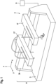
- FIG. 1 shows a schematic overview drawing of an exemplary laboratory workstation 2 which may be used in connection with a door 1 of the invention.
- This laboratory workstation 2 is shown without a door 1 for illustrative purpose.
- the laboratory workstation 2 comprises a work surface 3, which is shown here exemplarily as a continuous tabletop. Multi-part surfaces are however possible, too.
- Above the work surface 3 is a working area 4.
- the work surface 3 indicates a two-dimensional surface onto which for example laboratory articles 23, for example container with samples, or other devices 18 for automated process operations may be placed on, while the working area 4 refers to the three-dimensional space above the work surface 3, in which one or more robotic device 17 move for carrying out one or more process operations.
- Devices 18 which are required for automated processing and which may be placed onto a work surface are for example shakers for microplates, incubators, microscopes, centrifuges, etc.
- a user may have access to the work surface 3 and the working area 4 from the front side, which is the longitudinal side opposite to the guide rail 24 here.
- the access is controlled by a door, while the other sides of the work surface 3 are blocked for access, for example by housing components (not shown here).
- the laboratory workstation 2 shown comprises two robotic devices 17, one is configured as a gripping mechanism (see the arm on the right side), and one is configured as a pipetting head (see the arm on the left side).
- the gripping mechanism comprises here a gripper with two gripping fingers, while the pipetting head comprises two pipettes in this case.
- One of the pipettes is shown to have a pipette tip attached (pipette closer to the guide), while the other pipette is shown without an attached pipette tip, revealing the cone-type end.
- a processing unit 9 is configured to control the movements of each of the robotic devices 17 for carrying out an automated process operation, but also for avoiding potential collisions of present robotic devices 17. As discussed herein, the same processing unit 9 may be used for additionally controlling the position of a door 1, and to integrate the control of the door 1 with the control of the movement of the robotic device(s) 17 and the implementation of process operations, though a separate but functionally connected processing unit 9 is possible as well.
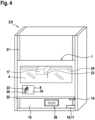
- FIG 2 shows a schematic overview drawing of an embodiment of a door 1 with an access opening 8 according to the invention in a frontal view.
- the access opening 8 is arranged in the lower part of the door 1.
- the door 1 shown here is particularly suitable for closing a working area 4 of a laboratory workstation 2, for example one as shown in Figure 1 , and is movable in a vertical direction.
- the vertical direction corresponds here to the z-direction as indicated in Figure 1 , which is perpendicular to the work surface.
- the door is a sliding door and is movable for example in relation to a work surface 3 by a door rail system comprising door rails 21.
- Door rails 21 may be anticipated on the right and left sides of the door 1 shown in Figure 2 and are shown explicitly in Figure 3 .
- the door 1 comprises at its lower side a grip rail 22.
- the processing unit 9 to which the locking mechanism 10 and the sensor 11 are functionally connected is not shown here.
- a locking mechanism 10 can be seen at the lower side, which is in this embodiment a simple mechanical stop.
- the locking mechanism 10 here is arranged in combination with a sensor 11.
- the mechanical stop may provide a locking function to hold the door 1 in the desired position for example in combination with a movable bolt (not shown), which bars the way of the mechanical stop when the bolt is extended and the door 1 is moved.
- a processing unit 9 (not shown here) may control whether the bolt is extended or retracted, thereby controlling whether the door 1 is kept in a desired position or may be moved out or moved over that position.
- An additional locking mechanism 10 which is coupled to a sensor 11 can be seen on the right side of the door 1.
- This locking mechanism 10 is shown to be shifted sideways to the mechanical stop at the bottom side. This has the advantage that this additional locking mechanism 10 does not interfere with e.g. the movable bolt.
- the additional locking mechanism 10 may interact with a separate counterpart instead (not shown), while the sensor 11 may indicate the status of this additional locking mechanism, for providing for example information to a processing unit 9 whether it is in a locking status or an open status.
- the door 1 is shown here for illustrative purposes being open in an area which may be covered by a transparent screen.
- a robotic device 17 in this case a pipetting head with a pipette and an attached pipette tip can be seen, as well as the guide rail 24 onto which the pipetting head is movably mounted.
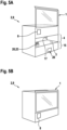
- An integrated processing unit 9 may coordinate the functioning of the liquid handing workstation with the integrated door 1.
- a locking mechanism 10 at the lower side of the door 1 may interact with a complementary locking mechanism 10 at the lower end of the liquid handling workstation. Both may form together one functional locking mechanism 10.
- a sensor 11 may be used for example to monitor whether the door is in the assigned position, or whether the locking mechanism is in an open or closed status, or both.
- the laboratory workstation 2 comprises an integrated processing unit 9 which is not explicitly shown in this Figure.
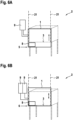
- a door 1 comprising an access opening 8 is shown to be mounted onto a laboratory workstation 2 and moved in a vertical direction into three different positions.
- Each laboratory workstation 2 comprises an integrated processing unit 9 here, which is not explicitly shown
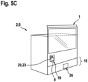
- Fig. 5A the door 1 is moved into an access position 7.
- the work surface 3 is fully accessible by a user, for example for equipping the work surface 3 for a certain process operation or for exchanging equipment.
- a pipetting head is shown being present as a robotic device 17.
- the laboratory workstation 2 is configured here as a liquid handling workstation.
- the pipetting head may move during an automated process operation through the working area 4, although in the access position, the movement of robotic devices 17 is stopped as a safeguard measurement.
- a processing unit 9 is functionally connected to the laboratory workstation 2 and the door 1 for coordinating one or more automated process operations and the door 1 interactively.
- the laboratory workstation 2 does not comprise an appliance compartment 15.
Landscapes
- Engineering & Computer Science (AREA)
- Civil Engineering (AREA)
- Structural Engineering (AREA)
- Chemical & Material Sciences (AREA)
- Health & Medical Sciences (AREA)
- Chemical Kinetics & Catalysis (AREA)
- Clinical Laboratory Science (AREA)
- Mechanical Engineering (AREA)
- Robotics (AREA)
- Physics & Mathematics (AREA)
- Life Sciences & Earth Sciences (AREA)
- Analytical Chemistry (AREA)
- Biochemistry (AREA)
- General Health & Medical Sciences (AREA)
- General Physics & Mathematics (AREA)
- Immunology (AREA)
- Pathology (AREA)
- Automatic Analysis And Handling Materials Therefor (AREA)
- Manipulator (AREA)
Claims (19)
- Eine Tür (1) eingebaut in ein Laborautomatisierungsgerät (2), wobei das Laborautomatisierungsgerät (2) eine horizontal verlaufende Arbeitsfläche (3) aufweist, um darauf einen Arbeitsbereich (4) bereitzustellen, wobei die Tür (1) in Bezug auf die Arbeitsfläche (3) in vertikaler Richtung senkrecht zur Arbeitsfläche (3) bewegbar ausgebildet ist und eine Zugangsöffnung (8) aufweist, die so ausgeführt ist, dass sie reversibel veränderbar ist zwischen einem Ladezustand oder einem geschlossenen Zustand zum Zulassen oder Einschränken eines eingeschränkten manuellen Zugriffs eines Benutzers auf den Arbeitsbereich (4),dadurch gekennzeichnet, dass das Laborautomatisierungsgerät (2) eine Verarbeitungseinheit (9) umfasst oder zum Anschliessen an eine externe Verarbeitungseinheit (9) ausgebildet ist,wobei die Tür (1) in Bezug auf die Arbeitsfläche (3) zwischen einer Sicherheitsposition (5), in der die Tür (1) den Arbeitsbereich (4) für den manuellen Zugang eines Benutzers schliesst, einer Zugangsposition (7), in der der Arbeitsbereich (4) für den manuellen Zugriff eines Benutzers geöffnet ist, und einer Ladeposition (6) bewegbar ist,wobei sich in der Sicherheitsposition (5) die Zugangsöffnung (8) im geschlossenen Zustand befindet, indem sie durch die Tür (1) unterhalb der Arbeitsfläche (3) positioniert ist, und wobei in der Ladeposition (6) die Zugangsöffnung (8) zur Arbeitsfläche (3) in den Ladezustand ausgerichtet ist, um einen eingeschränkten Zugang zum Arbeitsbereich (4) zu ermöglichen, undwobei die Position der Tür (1) durch die Verarbeitungseinheit (9) steuerbar ist, wobei die Verarbeitungseinheit (9) ausgeführt ist, um einen oder mehrere automatisierte Prozessvorgänge in dem Arbeitsbereich (4) oder Teilen davon in Abhängigkeit von der Position der Tür (1) zu steuern.
- Die Tür (1) nach Anspruch 1, wobei die Verarbeitungseinheit (9) dazu ausgebildet ist, um- einen oder mehrere automatisierte Prozessvorgänge in einem Teil des Arbeitsbereichs (4) zu ermöglichen, der durch die Zugangsöffnung (8) für einen Benutzer nicht zugänglich ist, wenn die Tür (1) in die Ladeposition (6) bewegt wird, und/oder- einen oder mehrere automatisierte Prozessvorgänge im gesamten Arbeitsbereich (4) zu ermöglichen, wenn die Tür (1) in die Sicherheitsposition (5) bewegt wird, und/oder- einen oder mehrere automatisierte Prozessvorgänge im Arbeitsbereich (4) oder in Teilen davon einzuschränken oder zu verhindern, wenn die Tür (1) in die Ladeposition (6) oder in die Zugangsposition (7) bewegt wird.
- Die Tür (1) nach einem der vorhergehenden Ansprüche, mit mindestens einem Sensor (11), der funktionell mit der Verarbeitungseinheit (9) verbunden ist, wobei der Sensor (11) zur Überwachung der Position der Tür (1) ausgebildet ist.
- Die Tür (1) nach einem der vorhergehenden Ansprüche, wobei sie - zum Verriegeln in der Sicherheitsposition (5) und/oder in der Ladeposition (6) - jeweils einen Verriegelungsmechanismus (10) aufweist, der funktionell mit der Verarbeitungseinheit (9) verbunden ist.
- Die Tür (1) nach Anspruch 4, wobei jeder Verriegelungsmechanismus (10) mit mindestens einem Sensor (11) funktionell verbunden ist.
- Die Tür (1) nach Anspruch 5, wobei die Verarbeitungseinheit (9) ausgestaltet ist, um:- einen Verriegelungsmechanismus (10) zu schliessen, um einen oder mehrere automatisierte Prozessvorgänge im Arbeitsbereich (4) oder Teilen davon auszuführen; und/oder- einen Verriegelungsmechanismus (10) verschlossen zu halten, wenn ein automatisierter Prozessvorgang im Arbeitsbereich (4) oder in Teilen davon durchgeführt wird; und/oder- einen oder mehrere automatisierte Prozessvorgänge im Arbeitsbereich (4) oder Teilen davon in Abhängigkeit vom Zustand des Verriegelungsmechanismus (10) zu veranlassen; und/oder- einen Verriegelungsmechanismus (10) in Abhängigkeit vom Status eines oder mehrerer automatisierter Prozessvorgänge zu öffnen, die im Arbeitsbereich (4) oder Teilen davon ausgeführt werden; und/oder- einen Verriegelungsmechanismus (10) offen zu halten, wenn im Arbeitsbereich (4) oder Teilen davon kein automatisierter Prozessvorgang durchgeführt wird; und/oder- den Status eines Verriegelungsmechanismus (10) zu steuern; und/oder- einen oder mehrere automatisierte Prozessvorgänge, die in dem Arbeitsbereich (4) oder Teilen davon ausgeführt werden, zu stoppen, wenn die Position der Tür (1) verändert wird oder wenn der Status eines Verriegelungsmechanismus geändert wird.
- Die Tür (1) nach einem der Ansprüche 4 bis 6, wobei der Verriegelungsmechanismus (10) aus einer Gruppe ausgewählt ist, die ein mechanisches Verriegelungssystem, ein elektrisches Verriegelungssystem und ein magnetisches Verriegelungssystem oder eine Kombination davon umfasst.
- Ein Laborautomatisierungsgerät (2), umfassend:- eine horizontal verlaufende Arbeitsfläche (3) um darauf einen Arbeitsbereich (4) bereitzustellen,- mindestens eine Robotervorrichtung (17) um einen oder mehrere Prozessvorgänge automatisiert auszuführen, und- eine Verarbeitungseinheit (9), die zur Steuerung eines oder mehrerer automatisierter Prozessvorgänge ausgeführt ist,wobei das Laborautomatisierungsgerät (2) ferner eine Tür (1) nach einem der Ansprüche 1 bis 7 aufweist,wobei die Tür (1) in Bezug auf die Arbeitsfläche (3) in vertikaler Richtung senkrecht zur Arbeitsfläche (3) zwischen einer Sicherheitsposition (5), in der die Tür (1) den Arbeitsbereich (4) für den manuellen Zugang eines Benutzers schliesst, einer Zugangsposition (7), in der der Arbeitsbereich (4) für den manuellen Zugriff eines Benutzers geöffnet ist, und einer Ladeposition (6) bewegbar ist,wobei die Tür (1) eine Zugangsöffnung (8) aufweist, die reversibel zwischen einem geöffneten Zustand, einem Ladezustand oder einem geschlossenen Zustand veränderbar ist,wobei sich in der Sicherheitsposition (5) die Zugangsöffnung (8) im geschlossenen Zustand befindet, indem sie durch die Tür (1) unterhalb der Arbeitsfläche (3) positioniert ist, und wobei in der Ladeposition (6) die Zugangsöffnung (8) zur Arbeitsfläche (3) ausgerichtet ist in den Ladezustand, um einen eingeschränkten Zugang zum Arbeitsbereich (4) zu ermöglichen, undwobei die Verarbeitungseinheit (9) des Laborautomatisierungsgeräts (2) ausgeführt ist, um eine Aktivität der mindestens einen Robotervorrichtung (17) zur Durchführung eines oder mehrerer automatisierter Prozessvorgänge im Arbeitsbereich (4) oder Teilen davon in Abhängigkeit von der Position der Tür (1) zu steuern.
- Das Laborautomatisierungsgerät (2) nach Anspruch 8, wobei die Tür (1) eine Schiebetür (1) ist, die entlang einer oder mehrerer Führungsschienen (21), die an dem Laborautomatisierungsgerät (2) angebracht sind, vertikal bewegbar ist.
- Das Laborautomatisierungsgerät (2) nach Anspruch 8 oder 9, wobei die Tür (1) und/oder das Laborautomatisierungsgerät (2) mindestens einen Sensor (11) aufweist, der funktionell mit der Verarbeitungseinheit (9) verbunden ist und der zur Überwachung der Position der Tür (1) in Bezug auf die Arbeitsfläche (3) des Laborautomatisierungsgeräts (2) ausgebildet ist.
- Das Laborautomatisierungsgerät (2) nach einem der Ansprüche 8 bis 10, wobei die Tür (1) und/oder das Laborautomatisierungsgerät (2) jeweils mindestens einen Verriegelungsmechanismus (10) zum Verriegeln der Tür (1) an dem Laborautomatisierungsgerät (2) in der Sicherheitsposition (5) und/oder in der Ladeposition (6) und/oder in der Zugangsposition (7) aufweist, wobei jeder Verriegelungsmechanismus (10) funktionell mit der Verarbeitungseinheit (9) verbunden ist.
- Das Laborautomatisierungsgerät (2) nach einem der Ansprüche 8 bis 11, mit einem Ladebereich (19) auf der Arbeitsfläche (3), der für einen Benutzer manuell durch die Zugangsöffnung (8) zugänglich ist, wenn sich die Zugangsöffnung (8) im Ladezustand befindet, wobei der Ladebereich (19) mindestens einen Träger (20) aufweist, der beweglich auf der Arbeitsfläche (3) befestigt ist, wobei der Träger (20) zur Aufnahme eines oder mehrerer Laborgegenstände (21) und zum Bewegen auf der Arbeitsfläche (3) und in Richtung der Zugangsöffnung (8) ausgebildet ist, wenn sich die Zugangsöffnung (8) im Ladezustand befindet.
- Das Laborautomatisierungsgerät (2) nach einem der Ansprüche 8 bis 12, wobei es unterhalb der Arbeitsfläche (3) ein Gerätefach (15) zur Aufnahme eines oder mehrerer Geräte (18) oder Teile davon aufweist, die zur Durchführung eines automatisierten Prozessvorgangs erforderlich sind.
- Ein Verfahren zum Steuern eines manuellen Zugangs zu einem Arbeitsbereich (4) eines Laborautomatisierungsgeräts (2), wobei das Verfahren die folgenden Schritte umfasst:- Bereitstellen eines Laborautomatisierungsgeräts (2), umfassend:- eine horizontal verlaufende Arbeitsfläche (3), um darauf einen Arbeitsbereich (4) bereitzustellen,- mindestens eine Robotervorrichtung (17) zur automatisierten Durchführung eines oder mehrerer Prozessvorgänge im Arbeitsbereich (4) steuerbar durch eine Verarbeitungseinheit (9),dadurch gekennzeichnet, dass das Laborautomatisierungsgerät (2) ferner umfasst:- eine Tür (1) nach einem der Ansprüche 1 bis 7, die senkrecht zur Arbeitsfläche (3) in vertikaler Richtung bewegbar ist, um den manuellen Zugang zum Arbeitsbereich (4) zu ermöglichen oder einzuschränken, und die eine Zugangsöffnung (8) aufweist, und- eine Verarbeitungseinheit (9), die dazu ausgeführt ist, um einen oder mehrere automatisierte Prozessvorgänge im Arbeitsbereich oder Teilen davon in Abhängigkeit von einer Position der Tür (1) zu steuern,- die Tür (1) in eine Sicherheitsposition (5) zu bringen und dadurch den Arbeitsbereich (4) für den manuellen Zugriff eines Benutzers zu schliessen, wobei die Verarbeitungseinheit (9) steuert, dass sich die Tür (1) in der Sicherheitsposition (5) befindet,- automatisiertes Ausführen eines oder mehrerer Prozessvorgänge im Arbeitsbereich (4) unter Verwendung mindestens einer Robotervorrichtung (17) gesteuert durch die Verarbeitungseinheit (9),- Anhalten des einen oder der mehreren Prozessvorgänge im Arbeitsbereich (4) oder Teilen davon und anschliessendes Verschieben der Tür (1) in eine Ladeposition (6), jeweils gesteuert durch die Verarbeitungseinheit (9),- Bewegen der Tür (1) aus der Sicherheitsposition (5) in die Ladeposition (6), um einem Benutzer einen eingeschränkten manuellen Zugang zum Arbeitsbereich (4) oder Teilen davon durch die Zugangsöffnung (8) zu ermöglichen, und Steuern der Tür (1), dass sie sich in der Ladeposition (6) befindet durch die Verarbeitungseinheit (9), und- Be- oder Entladen der Arbeitsfläche (3) durch die Zugangsöffnung (8), während der eine oder mehrere Prozessvorgänge angehalten ist und sich die Tür (1) in der Ladeposition (6) befindet, gesteuert durch die Verarbeitungseinheit (9).
- Das Verfahren nach Anspruch 14, wobei das Verfahren nach dem Be- oder Entladen der Arbeitsfläche (3) ferner den Schritt umfasst:- Bewegen der Tür (1) in die Sicherheitsposition (5) und Steuern der Tür (1) in der Sicherheitsposition (5) durch die Verarbeitungseinheit (9), und danach- Fortsetzen des angehaltenen einen oder mehrerer Prozessvorgänge auf dem Arbeitsbereich (4) durch Steuerung der Verarbeitungseinheit (9).
- Das Verfahren nach Anspruch 14 oder 15, wobei die Arbeitsfläche (3) des Laborautomatisierungsgeräts (2) einen Ladebereich (19) aufweist, der von einem Benutzer manuell durch die Zugangsöffnung (8) zugänglich ist, wenn sich die Tür (1) in der Ladeposition (6) befindet,wobei zum Be- oder Entladen der Arbeitsfläche (3), wenn sich die Tür (1) in der Ladeposition (6) befindet, Prozessvorgänge, die im Ladebereich (19) durchgeführt werden, gesteuert durch die Verarbeitungseinheit (9) pausiert werden, während ein oder mehrere andere Prozessvorgänge, die ausserhalb des Ladebereichs (19) im Arbeitsbereich (4) durchgeführt werden, fortgesetzt werden, oderalle Prozessvorgänge, die im Arbeitsbereich (4) ausgeführt werden, angehalten werden.
- Das Verfahren nach einem der Ansprüche 14 bis 16, wobei die Tür (1) und/oder das Laborautomatisierungsgerät (2) einen Verriegelungsmechanismus (10) zum Verriegeln der Tür (1) in der Sicherheitsposition (5) und/oder in der Ladeposition (6) und/oder in der Zugangsposition (7) aufweist, wobei der Verriegelungsmechanismus durch die Verarbeitungseinheit (9) gesteuert wird, wobei die Verarbeitungseinheit (9) einen oder mehrere automatisierte Prozessvorgänge in Abhängigkeit vom Status des Verriegelungsmechanismus (10) steuert.
- Das Verfahren nach Anspruch 17, wobei der Verriegelungsmechanismus (10) funktionell mit mindestens einem Sensor (11) verbunden ist, und wobei der Sensor (11) die Position der Tür (1) in Bezug auf die Arbeitsfläche (3) des Laborautomatisierungsgeräts (2) überwacht, indem er den Status des zugehörigen Verriegelungsmechanismus (10) überwacht.
- Das Verfahren nach Anspruch 18, wobei die Verarbeitungseinheit (9) folgendes steuert- dass ein Verriegelungsmechanismus (10) für die Tür (1) verriegelt bleibt, solange sich eine Robotervorrichtung (17) im Arbeitsbereich (4) bewegt, wenn die Tür (1) in der Sicherheitsposition (5) verriegelt ist, und/oder- dass der Verriegelungsmechanismus (10) der Tür (1) so lange verriegelt bleibt, wie sich eine Robotervorrichtung (17) im Arbeitsbereich (4), aber ausserhalb des Ladebereichs (19) bewegt, wenn die Tür (1) in der Ladeposition (6) verriegelt ist oder wenn die Tür (1) in der Sicherheitsposition (5) verriegelt ist, und/oder- dass sich eine Robotervorrichtung (17) des Laborautomatisierungsgeräts (2) nicht bewegt, wenn die Tür (1) in die Zugangsposition (7) bewegt oder in dieser verriegelt wird.
Priority Applications (3)
| Application Number | Priority Date | Filing Date | Title |
|---|---|---|---|
| EP20216944.7A EP4019130B1 (de) | 2020-12-23 | 2020-12-23 | Tür für ein laborautomatisierungsgerät |
| US17/553,363 US12486713B2 (en) | 2020-12-23 | 2021-12-16 | Door for a laboratory workstation |
| CN202111590329.4A CN114658335A (zh) | 2020-12-23 | 2021-12-23 | 用于实验室工作站的门 |
Applications Claiming Priority (1)
| Application Number | Priority Date | Filing Date | Title |
|---|---|---|---|
| EP20216944.7A EP4019130B1 (de) | 2020-12-23 | 2020-12-23 | Tür für ein laborautomatisierungsgerät |
Publications (2)
| Publication Number | Publication Date |
|---|---|
| EP4019130A1 EP4019130A1 (de) | 2022-06-29 |
| EP4019130B1 true EP4019130B1 (de) | 2024-07-10 |
Family
ID=73857073
Family Applications (1)
| Application Number | Title | Priority Date | Filing Date |
|---|---|---|---|
| EP20216944.7A Active EP4019130B1 (de) | 2020-12-23 | 2020-12-23 | Tür für ein laborautomatisierungsgerät |
Country Status (3)
| Country | Link |
|---|---|
| US (1) | US12486713B2 (de) |
| EP (1) | EP4019130B1 (de) |
| CN (1) | CN114658335A (de) |
Families Citing this family (7)
| Publication number | Priority date | Publication date | Assignee | Title |
|---|---|---|---|---|
| US12286813B2 (en) * | 2020-12-14 | 2025-04-29 | Husqvarna Ab | Selectively operable door for an autonomous device |
| US12157644B2 (en) | 2021-03-30 | 2024-12-03 | Dexterity, Inc. | Autonomous and safe integration of human task in robotic operation |
| US11897706B2 (en) | 2021-03-30 | 2024-02-13 | Dexterity, Inc. | Robotic system with zone-based control |
| US11981517B2 (en) * | 2021-03-30 | 2024-05-14 | Dexterity, Inc. | Robotic line kitting system safety features |
| US20250061758A1 (en) * | 2023-08-14 | 2025-02-20 | Andrew Alliance S.A. | Control system for laboratory enclosure |
| CN117181318A (zh) * | 2023-09-08 | 2023-12-08 | 中科美菱低温科技股份有限公司 | 一种反馈结构及生物安全柜 |
| DE102024116007A1 (de) | 2024-06-07 | 2025-12-11 | Precomb Therapeutics Ag | Kontinuierliche methode und verbesserte vorrichtung für die analyse von krebs-proben |
Citations (1)
| Publication number | Priority date | Publication date | Assignee | Title |
|---|---|---|---|---|
| DE8115894U1 (de) * | 1981-05-29 | 1982-02-04 | CEAG Verfahrenstechnik GmbH, 4714 Selm | Reinraumtechnische arbeitsstation |
Family Cites Families (4)
| Publication number | Priority date | Publication date | Assignee | Title |
|---|---|---|---|---|
| DE102013008019A1 (de) * | 2013-05-08 | 2014-11-13 | Thermo Electron Led Gmbh | Laborabzug mit neuartiger Arbeitsöffnung |
| DE102017109263B4 (de) * | 2017-04-28 | 2019-06-06 | Binder Gmbh | Laborschrank |
| CN110748266A (zh) * | 2018-07-24 | 2020-02-04 | 上海捷纳机电科技有限公司 | 一种通风柜柜门开关控制装置 |
| WO2023141123A1 (en) * | 2022-01-24 | 2023-07-27 | Beckman Coulter, Inc. | Methods of installation and service of a module in a laboratory workstation |
-
2020
- 2020-12-23 EP EP20216944.7A patent/EP4019130B1/de active Active
-
2021
- 2021-12-16 US US17/553,363 patent/US12486713B2/en active Active
- 2021-12-23 CN CN202111590329.4A patent/CN114658335A/zh active Pending
Patent Citations (1)
| Publication number | Priority date | Publication date | Assignee | Title |
|---|---|---|---|---|
| DE8115894U1 (de) * | 1981-05-29 | 1982-02-04 | CEAG Verfahrenstechnik GmbH, 4714 Selm | Reinraumtechnische arbeitsstation |
Also Published As
| Publication number | Publication date |
|---|---|
| US20220195752A1 (en) | 2022-06-23 |
| CN114658335A (zh) | 2022-06-24 |
| US12486713B2 (en) | 2025-12-02 |
| EP4019130A1 (de) | 2022-06-29 |
Similar Documents
| Publication | Publication Date | Title |
|---|---|---|
| EP4019130B1 (de) | Tür für ein laborautomatisierungsgerät | |
| US11754582B2 (en) | Automated diagnostic analyzer and method for its operation | |
| EP3430410B1 (de) | Verfahren zur automatischen analyse | |
| JP6193540B2 (ja) | 連続的装填のための供給ユニット | |
| US7264432B2 (en) | Device and method for transferring objects | |
| EP2290372B1 (de) | Analysiervorrichtung und Steuerverfahren dafür | |
| CN102597785A (zh) | 自动分析仪 | |
| AU2018240553B2 (en) | Cover assembly and related methods of use | |
| WO2018155049A1 (ja) | 自動分析装置 | |
| CN113533757B (zh) | 实验室样品器皿分配系统、操作方法以及体外诊断系统 | |
| WO2023086302A1 (en) | Automated pipette tip organizing for fluid handling systems | |
| US20250116681A1 (en) | Automatic analyzer | |
| JP2006177817A (ja) | 箱状物の供給装置、取り出し装置、棚段及び自動搬送システム | |
| EP3702034B1 (de) | System zum laden von pipettenspitzen | |
| JP5276085B2 (ja) | 箱状物ストッカ | |
| WO2025168438A1 (en) | Apparatus and container for automated diagnostic analysis of liquid samples | |
| CN120718747A (zh) | 样本分析仪 | |
| JP2017096980A (ja) | 検体処理装置および検体処理方法 |
Legal Events
| Date | Code | Title | Description |
|---|---|---|---|
| PUAI | Public reference made under article 153(3) epc to a published international application that has entered the european phase |
Free format text: ORIGINAL CODE: 0009012 |
|
| STAA | Information on the status of an ep patent application or granted ep patent |
Free format text: STATUS: THE APPLICATION HAS BEEN PUBLISHED |
|
| AK | Designated contracting states |
Kind code of ref document: A1 Designated state(s): AL AT BE BG CH CY CZ DE DK EE ES FI FR GB GR HR HU IE IS IT LI LT LU LV MC MK MT NL NO PL PT RO RS SE SI SK SM TR |
|
| STAA | Information on the status of an ep patent application or granted ep patent |
Free format text: STATUS: REQUEST FOR EXAMINATION WAS MADE |
|
| 17P | Request for examination filed |
Effective date: 20221229 |
|
| RBV | Designated contracting states (corrected) |
Designated state(s): AL AT BE BG CH CY CZ DE DK EE ES FI FR GB GR HR HU IE IS IT LI LT LU LV MC MK MT NL NO PL PT RO RS SE SI SK SM TR |
|
| P01 | Opt-out of the competence of the unified patent court (upc) registered |
Effective date: 20230523 |
|
| GRAP | Despatch of communication of intention to grant a patent |
Free format text: ORIGINAL CODE: EPIDOSNIGR1 |
|
| STAA | Information on the status of an ep patent application or granted ep patent |
Free format text: STATUS: GRANT OF PATENT IS INTENDED |
|
| RIC1 | Information provided on ipc code assigned before grant |
Ipc: G01N 35/00 20060101ALI20231130BHEP Ipc: B08B 15/02 20060101ALI20231130BHEP Ipc: B01L 1/00 20060101AFI20231130BHEP |
|
| INTG | Intention to grant announced |
Effective date: 20231222 |
|
| GRAJ | Information related to disapproval of communication of intention to grant by the applicant or resumption of examination proceedings by the epo deleted |
Free format text: ORIGINAL CODE: EPIDOSDIGR1 |
|
| STAA | Information on the status of an ep patent application or granted ep patent |
Free format text: STATUS: REQUEST FOR EXAMINATION WAS MADE |
|
| INTC | Intention to grant announced (deleted) | ||
| GRAP | Despatch of communication of intention to grant a patent |
Free format text: ORIGINAL CODE: EPIDOSNIGR1 |
|
| STAA | Information on the status of an ep patent application or granted ep patent |
Free format text: STATUS: GRANT OF PATENT IS INTENDED |
|
| GRAS | Grant fee paid |
Free format text: ORIGINAL CODE: EPIDOSNIGR3 |
|
| GRAA | (expected) grant |
Free format text: ORIGINAL CODE: 0009210 |
|
| STAA | Information on the status of an ep patent application or granted ep patent |
Free format text: STATUS: THE PATENT HAS BEEN GRANTED |
|
| INTG | Intention to grant announced |
Effective date: 20240514 |
|
| AK | Designated contracting states |
Kind code of ref document: B1 Designated state(s): AL AT BE BG CH CY CZ DE DK EE ES FI FR GB GR HR HU IE IS IT LI LT LU LV MC MK MT NL NO PL PT RO RS SE SI SK SM TR |
|
| REG | Reference to a national code |
Ref country code: CH Ref legal event code: EP |
|
| REG | Reference to a national code |
Ref country code: DE Ref legal event code: R096 Ref document number: 602020033684 Country of ref document: DE |
|
| REG | Reference to a national code |
Ref country code: LT Ref legal event code: MG9D |
|
| REG | Reference to a national code |
Ref country code: NL Ref legal event code: MP Effective date: 20240710 |
|
| PG25 | Lapsed in a contracting state [announced via postgrant information from national office to epo] |
Ref country code: PT Free format text: LAPSE BECAUSE OF FAILURE TO SUBMIT A TRANSLATION OF THE DESCRIPTION OR TO PAY THE FEE WITHIN THE PRESCRIBED TIME-LIMIT Effective date: 20241111 |
|
| REG | Reference to a national code |
Ref country code: AT Ref legal event code: MK05 Ref document number: 1701589 Country of ref document: AT Kind code of ref document: T Effective date: 20240710 |
|
| PG25 | Lapsed in a contracting state [announced via postgrant information from national office to epo] |
Ref country code: NL Free format text: LAPSE BECAUSE OF FAILURE TO SUBMIT A TRANSLATION OF THE DESCRIPTION OR TO PAY THE FEE WITHIN THE PRESCRIBED TIME-LIMIT Effective date: 20240710 |
|
| PG25 | Lapsed in a contracting state [announced via postgrant information from national office to epo] |
Ref country code: PT Free format text: LAPSE BECAUSE OF FAILURE TO SUBMIT A TRANSLATION OF THE DESCRIPTION OR TO PAY THE FEE WITHIN THE PRESCRIBED TIME-LIMIT Effective date: 20241111 Ref country code: NL Free format text: LAPSE BECAUSE OF FAILURE TO SUBMIT A TRANSLATION OF THE DESCRIPTION OR TO PAY THE FEE WITHIN THE PRESCRIBED TIME-LIMIT Effective date: 20240710 |
|
| PGFP | Annual fee paid to national office [announced via postgrant information from national office to epo] |
Ref country code: DE Payment date: 20241029 Year of fee payment: 5 |
|
| PG25 | Lapsed in a contracting state [announced via postgrant information from national office to epo] |
Ref country code: NO Free format text: LAPSE BECAUSE OF FAILURE TO SUBMIT A TRANSLATION OF THE DESCRIPTION OR TO PAY THE FEE WITHIN THE PRESCRIBED TIME-LIMIT Effective date: 20241010 |
|
| PG25 | Lapsed in a contracting state [announced via postgrant information from national office to epo] |
Ref country code: FI Free format text: LAPSE BECAUSE OF FAILURE TO SUBMIT A TRANSLATION OF THE DESCRIPTION OR TO PAY THE FEE WITHIN THE PRESCRIBED TIME-LIMIT Effective date: 20240710 Ref country code: PL Free format text: LAPSE BECAUSE OF FAILURE TO SUBMIT A TRANSLATION OF THE DESCRIPTION OR TO PAY THE FEE WITHIN THE PRESCRIBED TIME-LIMIT Effective date: 20240710 Ref country code: GR Free format text: LAPSE BECAUSE OF FAILURE TO SUBMIT A TRANSLATION OF THE DESCRIPTION OR TO PAY THE FEE WITHIN THE PRESCRIBED TIME-LIMIT Effective date: 20241011 |
|
| PGFP | Annual fee paid to national office [announced via postgrant information from national office to epo] |
Ref country code: GB Payment date: 20241031 Year of fee payment: 5 |
|
| PG25 | Lapsed in a contracting state [announced via postgrant information from national office to epo] |
Ref country code: BG Free format text: LAPSE BECAUSE OF FAILURE TO SUBMIT A TRANSLATION OF THE DESCRIPTION OR TO PAY THE FEE WITHIN THE PRESCRIBED TIME-LIMIT Effective date: 20240710 |
|
| PGFP | Annual fee paid to national office [announced via postgrant information from national office to epo] |
Ref country code: FR Payment date: 20241111 Year of fee payment: 5 |
|
| PG25 | Lapsed in a contracting state [announced via postgrant information from national office to epo] |
Ref country code: LV Free format text: LAPSE BECAUSE OF FAILURE TO SUBMIT A TRANSLATION OF THE DESCRIPTION OR TO PAY THE FEE WITHIN THE PRESCRIBED TIME-LIMIT Effective date: 20240710 |
|
| PG25 | Lapsed in a contracting state [announced via postgrant information from national office to epo] |
Ref country code: AT Free format text: LAPSE BECAUSE OF FAILURE TO SUBMIT A TRANSLATION OF THE DESCRIPTION OR TO PAY THE FEE WITHIN THE PRESCRIBED TIME-LIMIT Effective date: 20240710 Ref country code: IS Free format text: LAPSE BECAUSE OF FAILURE TO SUBMIT A TRANSLATION OF THE DESCRIPTION OR TO PAY THE FEE WITHIN THE PRESCRIBED TIME-LIMIT Effective date: 20241110 |
|
| PG25 | Lapsed in a contracting state [announced via postgrant information from national office to epo] |
Ref country code: HR Free format text: LAPSE BECAUSE OF FAILURE TO SUBMIT A TRANSLATION OF THE DESCRIPTION OR TO PAY THE FEE WITHIN THE PRESCRIBED TIME-LIMIT Effective date: 20240710 |
|
| PG25 | Lapsed in a contracting state [announced via postgrant information from national office to epo] |
Ref country code: ES Free format text: LAPSE BECAUSE OF FAILURE TO SUBMIT A TRANSLATION OF THE DESCRIPTION OR TO PAY THE FEE WITHIN THE PRESCRIBED TIME-LIMIT Effective date: 20240710 Ref country code: RS Free format text: LAPSE BECAUSE OF FAILURE TO SUBMIT A TRANSLATION OF THE DESCRIPTION OR TO PAY THE FEE WITHIN THE PRESCRIBED TIME-LIMIT Effective date: 20241010 |
|
| PG25 | Lapsed in a contracting state [announced via postgrant information from national office to epo] |
Ref country code: RS Free format text: LAPSE BECAUSE OF FAILURE TO SUBMIT A TRANSLATION OF THE DESCRIPTION OR TO PAY THE FEE WITHIN THE PRESCRIBED TIME-LIMIT Effective date: 20241010 Ref country code: PL Free format text: LAPSE BECAUSE OF FAILURE TO SUBMIT A TRANSLATION OF THE DESCRIPTION OR TO PAY THE FEE WITHIN THE PRESCRIBED TIME-LIMIT Effective date: 20240710 Ref country code: NO Free format text: LAPSE BECAUSE OF FAILURE TO SUBMIT A TRANSLATION OF THE DESCRIPTION OR TO PAY THE FEE WITHIN THE PRESCRIBED TIME-LIMIT Effective date: 20241010 Ref country code: LV Free format text: LAPSE BECAUSE OF FAILURE TO SUBMIT A TRANSLATION OF THE DESCRIPTION OR TO PAY THE FEE WITHIN THE PRESCRIBED TIME-LIMIT Effective date: 20240710 Ref country code: IS Free format text: LAPSE BECAUSE OF FAILURE TO SUBMIT A TRANSLATION OF THE DESCRIPTION OR TO PAY THE FEE WITHIN THE PRESCRIBED TIME-LIMIT Effective date: 20241110 Ref country code: HR Free format text: LAPSE BECAUSE OF FAILURE TO SUBMIT A TRANSLATION OF THE DESCRIPTION OR TO PAY THE FEE WITHIN THE PRESCRIBED TIME-LIMIT Effective date: 20240710 Ref country code: GR Free format text: LAPSE BECAUSE OF FAILURE TO SUBMIT A TRANSLATION OF THE DESCRIPTION OR TO PAY THE FEE WITHIN THE PRESCRIBED TIME-LIMIT Effective date: 20241011 Ref country code: FI Free format text: LAPSE BECAUSE OF FAILURE TO SUBMIT A TRANSLATION OF THE DESCRIPTION OR TO PAY THE FEE WITHIN THE PRESCRIBED TIME-LIMIT Effective date: 20240710 Ref country code: ES Free format text: LAPSE BECAUSE OF FAILURE TO SUBMIT A TRANSLATION OF THE DESCRIPTION OR TO PAY THE FEE WITHIN THE PRESCRIBED TIME-LIMIT Effective date: 20240710 Ref country code: BG Free format text: LAPSE BECAUSE OF FAILURE TO SUBMIT A TRANSLATION OF THE DESCRIPTION OR TO PAY THE FEE WITHIN THE PRESCRIBED TIME-LIMIT Effective date: 20240710 Ref country code: AT Free format text: LAPSE BECAUSE OF FAILURE TO SUBMIT A TRANSLATION OF THE DESCRIPTION OR TO PAY THE FEE WITHIN THE PRESCRIBED TIME-LIMIT Effective date: 20240710 |
|
| REG | Reference to a national code |
Ref country code: DE Ref legal event code: R097 Ref document number: 602020033684 Country of ref document: DE |
|
| PG25 | Lapsed in a contracting state [announced via postgrant information from national office to epo] |
Ref country code: RO Free format text: LAPSE BECAUSE OF FAILURE TO SUBMIT A TRANSLATION OF THE DESCRIPTION OR TO PAY THE FEE WITHIN THE PRESCRIBED TIME-LIMIT Effective date: 20240710 Ref country code: DK Free format text: LAPSE BECAUSE OF FAILURE TO SUBMIT A TRANSLATION OF THE DESCRIPTION OR TO PAY THE FEE WITHIN THE PRESCRIBED TIME-LIMIT Effective date: 20240710 Ref country code: SM Free format text: LAPSE BECAUSE OF FAILURE TO SUBMIT A TRANSLATION OF THE DESCRIPTION OR TO PAY THE FEE WITHIN THE PRESCRIBED TIME-LIMIT Effective date: 20240710 |
|
| PG25 | Lapsed in a contracting state [announced via postgrant information from national office to epo] |
Ref country code: EE Free format text: LAPSE BECAUSE OF FAILURE TO SUBMIT A TRANSLATION OF THE DESCRIPTION OR TO PAY THE FEE WITHIN THE PRESCRIBED TIME-LIMIT Effective date: 20240710 |
|
| PGFP | Annual fee paid to national office [announced via postgrant information from national office to epo] |
Ref country code: CH Payment date: 20250101 Year of fee payment: 5 |
|
| PG25 | Lapsed in a contracting state [announced via postgrant information from national office to epo] |
Ref country code: CZ Free format text: LAPSE BECAUSE OF FAILURE TO SUBMIT A TRANSLATION OF THE DESCRIPTION OR TO PAY THE FEE WITHIN THE PRESCRIBED TIME-LIMIT Effective date: 20240710 |
|
| PG25 | Lapsed in a contracting state [announced via postgrant information from national office to epo] |
Ref country code: SK Free format text: LAPSE BECAUSE OF FAILURE TO SUBMIT A TRANSLATION OF THE DESCRIPTION OR TO PAY THE FEE WITHIN THE PRESCRIBED TIME-LIMIT Effective date: 20240710 Ref country code: IT Free format text: LAPSE BECAUSE OF FAILURE TO SUBMIT A TRANSLATION OF THE DESCRIPTION OR TO PAY THE FEE WITHIN THE PRESCRIBED TIME-LIMIT Effective date: 20240710 |
|
| PLBE | No opposition filed within time limit |
Free format text: ORIGINAL CODE: 0009261 |
|
| STAA | Information on the status of an ep patent application or granted ep patent |
Free format text: STATUS: NO OPPOSITION FILED WITHIN TIME LIMIT |
|
| 26N | No opposition filed |
Effective date: 20250411 |
|
| PG25 | Lapsed in a contracting state [announced via postgrant information from national office to epo] |
Ref country code: MC Free format text: LAPSE BECAUSE OF FAILURE TO SUBMIT A TRANSLATION OF THE DESCRIPTION OR TO PAY THE FEE WITHIN THE PRESCRIBED TIME-LIMIT Effective date: 20240710 |
|
| PG25 | Lapsed in a contracting state [announced via postgrant information from national office to epo] |
Ref country code: LU Free format text: LAPSE BECAUSE OF NON-PAYMENT OF DUE FEES Effective date: 20241223 |
|
| PG25 | Lapsed in a contracting state [announced via postgrant information from national office to epo] |
Ref country code: SE Free format text: LAPSE BECAUSE OF FAILURE TO SUBMIT A TRANSLATION OF THE DESCRIPTION OR TO PAY THE FEE WITHIN THE PRESCRIBED TIME-LIMIT Effective date: 20240710 |
|
| REG | Reference to a national code |
Ref country code: BE Ref legal event code: MM Effective date: 20241231 |
|
| PG25 | Lapsed in a contracting state [announced via postgrant information from national office to epo] |
Ref country code: BE Free format text: LAPSE BECAUSE OF NON-PAYMENT OF DUE FEES Effective date: 20241231 |
|
| PG25 | Lapsed in a contracting state [announced via postgrant information from national office to epo] |
Ref country code: IE Free format text: LAPSE BECAUSE OF NON-PAYMENT OF DUE FEES Effective date: 20241223 |