EP4018082B1 - Raffiniervorrichtung zum raffinieren einer flüssigkeit - Google Patents
Raffiniervorrichtung zum raffinieren einer flüssigkeit Download PDFInfo
- Publication number
- EP4018082B1 EP4018082B1 EP20835725.1A EP20835725A EP4018082B1 EP 4018082 B1 EP4018082 B1 EP 4018082B1 EP 20835725 A EP20835725 A EP 20835725A EP 4018082 B1 EP4018082 B1 EP 4018082B1
- Authority
- EP
- European Patent Office
- Prior art keywords
- liquid
- air
- receiving plate
- liquid receiving
- refiner
- Prior art date
- Legal status (The legal status is an assumption and is not a legal conclusion. Google has not performed a legal analysis and makes no representation as to the accuracy of the status listed.)
- Active
Links
Images

Classifications
-
- F—MECHANICAL ENGINEERING; LIGHTING; HEATING; WEAPONS; BLASTING
- F01—MACHINES OR ENGINES IN GENERAL; ENGINE PLANTS IN GENERAL; STEAM ENGINES
- F01M—LUBRICATING OF MACHINES OR ENGINES IN GENERAL; LUBRICATING INTERNAL COMBUSTION ENGINES; CRANKCASE VENTILATING
- F01M1/00—Pressure lubrication
- F01M1/10—Lubricating systems characterised by the provision therein of lubricant venting or purifying means, e.g. of filters
-
- B—PERFORMING OPERATIONS; TRANSPORTING
- B01—PHYSICAL OR CHEMICAL PROCESSES OR APPARATUS IN GENERAL
- B01D—SEPARATION
- B01D3/00—Distillation or related exchange processes in which liquids are contacted with gaseous media, e.g. stripping
- B01D3/34—Distillation or related exchange processes in which liquids are contacted with gaseous media, e.g. stripping with one or more auxiliary substances
- B01D3/343—Distillation or related exchange processes in which liquids are contacted with gaseous media, e.g. stripping with one or more auxiliary substances the substance being a gas
- B01D3/346—Distillation or related exchange processes in which liquids are contacted with gaseous media, e.g. stripping with one or more auxiliary substances the substance being a gas the gas being used for removing vapours, e.g. transport gas
-
- B—PERFORMING OPERATIONS; TRANSPORTING
- B01—PHYSICAL OR CHEMICAL PROCESSES OR APPARATUS IN GENERAL
- B01D—SEPARATION
- B01D1/00—Evaporating
- B01D1/0011—Heating features
-
- B—PERFORMING OPERATIONS; TRANSPORTING
- B01—PHYSICAL OR CHEMICAL PROCESSES OR APPARATUS IN GENERAL
- B01D—SEPARATION
- B01D1/00—Evaporating
- B01D1/22—Evaporating by bringing a thin layer of the liquid into contact with a heated surface
-
- B—PERFORMING OPERATIONS; TRANSPORTING
- B01—PHYSICAL OR CHEMICAL PROCESSES OR APPARATUS IN GENERAL
- B01D—SEPARATION
- B01D1/00—Evaporating
- B01D1/22—Evaporating by bringing a thin layer of the liquid into contact with a heated surface
- B01D1/222—In rotating vessels; vessels with movable parts
-
- B—PERFORMING OPERATIONS; TRANSPORTING
- B01—PHYSICAL OR CHEMICAL PROCESSES OR APPARATUS IN GENERAL
- B01D—SEPARATION
- B01D3/00—Distillation or related exchange processes in which liquids are contacted with gaseous media, e.g. stripping
- B01D3/34—Distillation or related exchange processes in which liquids are contacted with gaseous media, e.g. stripping with one or more auxiliary substances
- B01D3/343—Distillation or related exchange processes in which liquids are contacted with gaseous media, e.g. stripping with one or more auxiliary substances the substance being a gas
-
- F—MECHANICAL ENGINEERING; LIGHTING; HEATING; WEAPONS; BLASTING
- F01—MACHINES OR ENGINES IN GENERAL; ENGINE PLANTS IN GENERAL; STEAM ENGINES
- F01M—LUBRICATING OF MACHINES OR ENGINES IN GENERAL; LUBRICATING INTERNAL COMBUSTION ENGINES; CRANKCASE VENTILATING
- F01M5/00—Heating, cooling, or controlling temperature of lubricant; Lubrication means facilitating engine starting
- F01M5/001—Heating
-
- F—MECHANICAL ENGINEERING; LIGHTING; HEATING; WEAPONS; BLASTING
- F02—COMBUSTION ENGINES; HOT-GAS OR COMBUSTION-PRODUCT ENGINE PLANTS
- F02M—SUPPLYING COMBUSTION ENGINES IN GENERAL WITH COMBUSTIBLE MIXTURES OR CONSTITUENTS THEREOF
- F02M37/00—Apparatus or systems for feeding liquid fuel from storage containers to carburettors or fuel-injection apparatus; Arrangements for purifying liquid fuel specially adapted for, or arranged on, internal-combustion engines
- F02M37/22—Arrangements for purifying liquid fuel specially adapted for, or arranged on, internal-combustion engines, e.g. arrangements in the feeding system
- F02M37/30—Arrangements for purifying liquid fuel specially adapted for, or arranged on, internal-combustion engines, e.g. arrangements in the feeding system characterised by heating means
-
- F—MECHANICAL ENGINEERING; LIGHTING; HEATING; WEAPONS; BLASTING
- F02—COMBUSTION ENGINES; HOT-GAS OR COMBUSTION-PRODUCT ENGINE PLANTS
- F02M—SUPPLYING COMBUSTION ENGINES IN GENERAL WITH COMBUSTIBLE MIXTURES OR CONSTITUENTS THEREOF
- F02M37/00—Apparatus or systems for feeding liquid fuel from storage containers to carburettors or fuel-injection apparatus; Arrangements for purifying liquid fuel specially adapted for, or arranged on, internal-combustion engines
- F02M37/22—Arrangements for purifying liquid fuel specially adapted for, or arranged on, internal-combustion engines, e.g. arrangements in the feeding system
- F02M37/32—Arrangements for purifying liquid fuel specially adapted for, or arranged on, internal-combustion engines, e.g. arrangements in the feeding system characterised by filters or filter arrangements
- F02M37/38—Arrangements for purifying liquid fuel specially adapted for, or arranged on, internal-combustion engines, e.g. arrangements in the feeding system characterised by filters or filter arrangements with regeneration means
-
- F—MECHANICAL ENGINEERING; LIGHTING; HEATING; WEAPONS; BLASTING
- F16—ENGINEERING ELEMENTS AND UNITS; GENERAL MEASURES FOR PRODUCING AND MAINTAINING EFFECTIVE FUNCTIONING OF MACHINES OR INSTALLATIONS; THERMAL INSULATION IN GENERAL
- F16N—LUBRICATING
- F16N39/00—Arrangements for conditioning of lubricants in the lubricating system
- F16N39/002—Arrangements for conditioning of lubricants in the lubricating system by deaeration
-
- F—MECHANICAL ENGINEERING; LIGHTING; HEATING; WEAPONS; BLASTING
- F16—ENGINEERING ELEMENTS AND UNITS; GENERAL MEASURES FOR PRODUCING AND MAINTAINING EFFECTIVE FUNCTIONING OF MACHINES OR INSTALLATIONS; THERMAL INSULATION IN GENERAL
- F16N—LUBRICATING
- F16N39/00—Arrangements for conditioning of lubricants in the lubricating system
- F16N39/005—Arrangements for conditioning of lubricants in the lubricating system by evaporating or purifying
-
- F—MECHANICAL ENGINEERING; LIGHTING; HEATING; WEAPONS; BLASTING
- F16—ENGINEERING ELEMENTS AND UNITS; GENERAL MEASURES FOR PRODUCING AND MAINTAINING EFFECTIVE FUNCTIONING OF MACHINES OR INSTALLATIONS; THERMAL INSULATION IN GENERAL
- F16N—LUBRICATING
- F16N39/00—Arrangements for conditioning of lubricants in the lubricating system
- F16N39/04—Arrangements for conditioning of lubricants in the lubricating system by heating
-
- F—MECHANICAL ENGINEERING; LIGHTING; HEATING; WEAPONS; BLASTING
- F24—HEATING; RANGES; VENTILATING
- F24H—FLUID HEATERS, e.g. WATER OR AIR HEATERS, HAVING HEAT-GENERATING MEANS, e.g. HEAT PUMPS, IN GENERAL
- F24H1/00—Water heaters, e.g. boilers, continuous-flow heaters or water-storage heaters
- F24H1/0018—Water heaters, e.g. boilers, continuous-flow heaters or water-storage heaters using electric energy supply
-
- F—MECHANICAL ENGINEERING; LIGHTING; HEATING; WEAPONS; BLASTING
- F01—MACHINES OR ENGINES IN GENERAL; ENGINE PLANTS IN GENERAL; STEAM ENGINES
- F01M—LUBRICATING OF MACHINES OR ENGINES IN GENERAL; LUBRICATING INTERNAL COMBUSTION ENGINES; CRANKCASE VENTILATING
- F01M1/00—Pressure lubrication
- F01M1/10—Lubricating systems characterised by the provision therein of lubricant venting or purifying means, e.g. of filters
- F01M2001/1007—Lubricating systems characterised by the provision therein of lubricant venting or purifying means, e.g. of filters characterised by the purification means combined with other functions
- F01M2001/1021—Lubricating systems characterised by the provision therein of lubricant venting or purifying means, e.g. of filters characterised by the purification means combined with other functions comprising self cleaning systems
-
- F—MECHANICAL ENGINEERING; LIGHTING; HEATING; WEAPONS; BLASTING
- F02—COMBUSTION ENGINES; HOT-GAS OR COMBUSTION-PRODUCT ENGINE PLANTS
- F02M—SUPPLYING COMBUSTION ENGINES IN GENERAL WITH COMBUSTIBLE MIXTURES OR CONSTITUENTS THEREOF
- F02M31/00—Apparatus for thermally treating combustion-air, fuel, or fuel-air mixture
- F02M31/02—Apparatus for thermally treating combustion-air, fuel, or fuel-air mixture for heating
- F02M31/16—Other apparatus for heating fuel
- F02M31/18—Other apparatus for heating fuel to vaporise fuel
- F02M31/186—Other apparatus for heating fuel to vaporise fuel with simultaneous mixing of secondary air
-
- F—MECHANICAL ENGINEERING; LIGHTING; HEATING; WEAPONS; BLASTING
- F24—HEATING; RANGES; VENTILATING
- F24H—FLUID HEATERS, e.g. WATER OR AIR HEATERS, HAVING HEAT-GENERATING MEANS, e.g. HEAT PUMPS, IN GENERAL
- F24H2250/00—Electrical heat generating means
- F24H2250/04—Positive temperature coefficients [PTC]; Negative temperature coefficients [NTC]
Definitions
- the device may include a particle filter that initially cleans the oil from particles and a liquid separation part intended for separating liquid in the form of water and fuel from the particle free oil.
- the liquid separation part can be provided in several different ways, e.g. as a substantially dome shaped heating plate.
- the heat plate may typically be shaped and arranged so that the oil remains on the heating plate for a certain period of time. In this manner, the complete oil film is brought to a temperature, by the heating plate, where the liquid can evaporate from the oil which remains on the plate.
- Another problem relates to the fact that the outdoor temperature often differs in different climates and in different parts of the world, which affects the temperature of the oil entering the liquid separation part. Cold conditions give colder oil and further energy is therefore required in order for the oil to reach the right temperature. Warm conditions, on the other hand, give warmer oil requiring the heat from the heat plate to be regulated to compensate the heat increase in order for the oil not to reach too high temperature.
- a properly working regulating arrangement for the heat plate is thus necessary for making the system work properly.
- Such a regulating arrangement comprises thermostats and other regulators comprising moving parts which in this context is a possible cause for malfunction, causing limited useful life and often undesired high oil temperatures. Such a regulating arrangement is also expensive and hard to install.
- WO2017093470A1 discloses an oil refinery device where oil or fuel is fed to a heated plate arranged in a housing and where air is fed to and from the housing so as to transport away contaminates evaporated from the oil or fuel.
- the plate is heated by point heat sources.
- US2785109A discloses a refiner device according to the pre-amble of claim 1.
- An object of this invention is to provide a refinery device that exhibit an improved refinery efficiency compared to conventional refinery devices, but that still provides for easy installation and use in existing systems. This object is achieved by the device defined by the technical features contained in claim 1.
- the dependent claims contain advantageous embodiments, further developments and variants of the invention.
- the invention concerns a refiner device for refining of a liquid, such as oil or fuel
- the refiner device comprises a housing provided with a liquid inlet for unrefined oil or fuel, a liquid outlet for refined oil or fuel, an air inlet for supplying a flow of air into the housing, and an air outlet for discharging air and contaminants removed from the liquid.
- the refiner device further comprises a liquid receiving plate arranged inside the housing, wherein the refiner device is arranged such that when liquid has passed through the liquid inlet during operation of the device, the liquid is contacted with an upper side of the liquid receiving plate before it reaches the liquid outlet.
- the refiner device further comprises at least one heating element arranged to directly or indirectly heat the liquid while the liquid is in contact with the liquid receiving plate.
- the refiner device may be of the type exemplified in, for instance, WO2017093470A1 where unrefined oil or fuel liquid is deposited onto and allowed to flow over a substantially horizontal, or at least not too inclined, heated plate or similar before it flows further down to an outlet.
- the expression "the liquid is contacted with an upper side of the liquid receiving plate” thus relates to the situation when the device has been properly oriented for being operated.
- the at least one air passage thus provides a flow communication between the air outlet inside the hollow air-guiding member and the air inlet outside of said member. And the air passage is arranged in association with the liquid receiving plate so as to force the air flow closer to the plate.
- An advantageous effect of such a design is that the air flow, preferably the entire air flow, is forced to pass closer to the heated liquid located on the liquid receiving plate on its way towards the air outlet. This makes the transfer of (evaporated) contaminants from the liquid to the air much more efficient compared to e.g. the device of WO2017093470A1 where the air flow is not forced to pass along the plate but instead can take almost any path inside the housing from the air inlet to the air outlet and thus might pass through the housing without coming into contact with the heated liquid.
- the device is arranged so that liquid that enters the housing via the liquid inlet during operation of the device is deposited onto a first point of the liquid receiving plate and so that the deposited liquid flows upon the liquid receiving plate in a direction towards a second point of the liquid receiving plate, and wherein the at least one air passage is arranged at the second point of the liquid receiving plate so as to, during operation of the device, force air to flow in a general direction towards the first point of the liquid receiving plate, i.e. in a direction generally opposite to that of the liquid flow.
- a main effect of such an embodiment is that a counter-current flow is obtained at the liquid receiving plate during operation of the device in that the liquid flows on the plate in one direction and the air flows above the plate in the opposite direction.
- a counter-current flow further increases the transfer of contaminants from the liquid to the air flow and thus further increases the refining efficiency.
- a counter-current flow of this type can be obtained by directing the incoming liquid towards a certain point of the liquid receiving plate, adapting the plate so that the liquid flows from that point in a certain direction, such as towards an edge of the plate, and locating the air passage leading into the hollow air-guiding member so that the air flows in the opposite direction in relation to the liquid.
- the liquid receiving plate may have another shape than a circular disc, and the air passage(s) may have another design.
- the liquid receiving plate may have a rectangular shape, in which case the liquid may be deposited at a first end of the plate and the air passage may be arranged at a second opposite end of the plate (where the device is arranged so that the liquid flows from the first to the second end of the plate during operation).
- the hollow air-guiding member comprises a funnel shaped element having a wide side and an opposite narrow side, wherein the funnel shaped element is arranged at the liquid receiving plate with its wide side facing the liquid receiving plate.
- a funnel shaped air-guiding member is well adapted for a liquid receiving plate have the shape of a circular disc.
- the at least one air passage is distributed around a perimeter of the liquid receiving plate.
- the air passage may be a single opening that extends along the perimeter or a plurality of openings distributed along the perimeter. Such a plurality of openings may or may not be evenly distributed along the perimeter depending on the design of the liquid receiving plate.
- liquid receiving plate and the hollow air-guiding member are separate components arranged at a distance from each other, wherein said distance forms the at least one air passage.
- the plate and the air-guiding member may or may not be connected directly to each other.
- liquid inlet is arranged inside of the hollow air-guiding member. This facilitates depositing the liquid properly onto the liquid receiving plate.
- liquid inlet thus here refers to the position where the liquid is introduced into the housing of the device, i.e. "the outlet of the liquid inlet”.
- the at least one heating element is a PTC ceramic element.
- PTC elements positive thermal coefficient of resistance
- PTC ceramic heating elements are well known as such.
- the at least one heating element is arranged to heat the liquid receiving plate.
- the heating element(s) thus heat(s) the liquid indirectly, via the plate.
- the device comprises a plurality of distributed heating elements. This provides for an even distribution of the temperature, in particular where the heating elements heat the liquid receiving plate (that in turn heats the liquid).
- the device comprises an air flow control system configured to control supply and/or quality of the air fed to the air inlet during operation of the device. In most applications it is important to control the mass flow rate of the air properly.
- the control system may also control e.g. pre-drying of the air.
- the liquid inlet is arranged in an upper part of the housing.
- the liquid outlet is arranged in a lower part of the housing. The liquid may thus flow through the device downwardly using only gravity as the driving force.
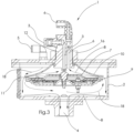
- the refiner device 1 comprises a housing 2 provided with a liquid inlet 3 for unrefined oil or fuel, a liquid outlet 4 for refined oil or fuel, an air inlet 5 for supplying a flow of air into the housing 2, and an air outlet 6 for discharging air and contaminants removed from the liquid.
- the liquid outlet 4 is arranged on a lower side 2b of the housing 2, whereas the air outlet 6 and the two inlets 3, 5 are arranged on an upper side 2a of the housing 2.
- An electric connection 25 for supplying electric power to heating elements 9 arranged inside the housing 2 is also provided on the upper side 2a of the housing 2.
- the electric connection 25 is also arranged to provide for control of the heating elements 9.
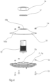
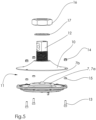
- the liquid receiving plate 7 and the funnel shaped element 10 are connected to each other by means of screws 13 and nuts 14.
- Distance elements 15 are provided between the liquid receiving plate 7 and the funnel shaped element 10 so as to create the annular air passage 11.
Landscapes
- Engineering & Computer Science (AREA)
- General Engineering & Computer Science (AREA)
- Mechanical Engineering (AREA)
- Chemical & Material Sciences (AREA)
- Chemical Kinetics & Catalysis (AREA)
- Combustion & Propulsion (AREA)
- Physics & Mathematics (AREA)
- Thermal Sciences (AREA)
- Vaporization, Distillation, Condensation, Sublimation, And Cold Traps (AREA)
- Production Of Liquid Hydrocarbon Mixture For Refining Petroleum (AREA)
- Physical Or Chemical Processes And Apparatus (AREA)
Claims (13)
- Raffiniervorrichtung (1) zum Raffinieren einer Flüssigkeit, wie etwa Öl oder Kraftstoff, wobei die Raffiniervorrichtung Folgendes umfasst: ein Gehäuse (2), das mit einem Flüssigkeitseinlass (3) für unraffiniertes Öl oder unraffinierten Kraftstoff bereitgestellt ist, einen Flüssigkeitsauslass (4) für raffiniertes Öl oder raffinierten Kraftstoff, einen Lufteinlass (5) zum Zuführen eines Luftstroms in das Gehäuse und einen Luftauslass (6) zum Abgeben von Luft und Verunreinigungen, die aus der Flüssigkeit entfernt wurden,wobei die Raffiniervorrichtung (1) fermer eine Flüssigkeitsaufnahmeplatte (7) umfasst, die innerhalb des Gehäuses (2) angeordnet ist,wobei die Raffiniervorrichtung (1) derart angeordnet ist, dass, wenn Flüssigkeit während eines Betriebs der Vorrichtung durch den Flüssigkeitseinlass (3) geleitet wurde, die Flüssigkeit mit einer oberen Fläche (7a) der Flüssigkeitsaufnahmeplatte (7) in Kontakt tritt, bevor sie den Flüssigkeitsauslass (4) erreicht,wobei die Raffiniervorrichtung (1) ferner mindestens ein Heizelement (9) umfasst, das dazu angeordnet ist, die Flüssigkeit direkt oder indirekt zu erhitzen, während die Flüssigkeit mit der Flüssigkeitsaufnahmeplatte (7) in Kontakt steht,dadurch gekennzeichnet,dass die Raffiniervorrichtung (1) ein hohles Luftführungselement (10) umfasst, das an der Flüssigkeitsaufnahmeplatte (7) angeordnet ist,wobei das hohle Luftführungselement (10) eine offene Sete (10a) aufweist, die der oberen Fläche (7a) der Flüssigkeitsaufnahmeplatte (7) zugewandt ist,wobei sich der Lufteinlass (5) außerhalb des hohlen Luftführungselements (10) befindet,wobei sich der Luftauslass (6) innerhalb des hohlen Luftführungselements (10) befindet,wobei mindestens ein Luftdurchgang (11) in das hohle Luftführungselement (10) an der Flüssigkeitsaufnahmeplatte (7) angeordnet ist, um, wenn Luft von dem Lufteinlass (5) durch das Gehäuse (2) zu dem Luftauslass (6) gespeist wird, Luft entlang mindestens eines Teils der Flüssigkeitsaufnahmeplatte (7) zu drängen, wenn sie durch den Luftdurchgang (11) strömt und/oder wenn sie weiter in das hohle Luftführungselement (10) in Richtung des Luftauslasses (6) strömt.
- Raffiniervorrichtung nach Anspruch 1, wobei die Vorrichtung derart angeordnet ist, dass die Flüssigkeit, die während eines Betriebs der Vorrichtung über den Flüssigkeitseinlass in das Gehäuse eintritt, an einem ersten Punkt der Flüssigkeitsaufnahmeplatte abgeschieden wird und dass die abgeschiedene Flüssigkeit auf der Flüssigkeitsaufnahmeplatte in eine Richtung zu einem zweiten Punkt der Flüssigkeitsaufnahmeplatte strömt, und wobei der mindestens eine Luftdurchgang an dem zweiten Punkt der Flüssigkeitsaufnahmeplatte angeordnet ist, sodass Luft während eines Betriebs der Vorrichtung dazu gedrängt wird, in eine allgemeine Richtung zu dem ersten Punkt der Flüssigkeitsaufnahmeplatte zu strömen, d. h. in einer Richtung, die im Allgemeinen der des Flüssigkeitsstroms entgegengesetzt ist.
- Raffiniervorrichtung nach Anspruch 2, wobei der erste Punkt ein zentraler Punkt der Flüssigkeitsaufnahmeplatte ist, wobei die Vorrichtung derart angeordnet ist, dass die an dem ersten, zentralen Punkt abgeschiedene Flüssigkeit von dem ersten, zentralen Punkt radial nach außen zu einem Umfang strömt, wobei sich der zweite Punkt an dem Umfang befindet.
- Raffiniervorrichtung nach einem der vorangehenden Ansprüche, wobei das hohle Luftführungselement ein trichterförmiges Element umfasst, das eine breite Seite und eine gegenüberliegende schmale Seite aufweist, wobei das trichterförmige Element so an der Flüssigkeitsaufnahmeplatte angeordnet ist, dass seine breite Seite der Flüssigkeitsaufnahmeplatte zugewandt ist.
- Raffiniervorrichtung nach einem der vorangehenden Ansprüche, wobei der mindestens eine Luftdurchgang um einen Umfang der Flüssigkeitsaufnahmeplatte verteilt ist.
- Raffiniervorrichtung nach einem der vorangehenden Ansprüche, wobei die Flüssigkeitsaufnahmeplatte und das hohle Luftführungselement getrennte Komponenten sind, die in einer Entfernung voneinander angeordnet sind, wobei die Entfernung den mindestens einen Luftdurchgang bildet.
- Raffiniervorrichtung nach einem der vorangehenden Ansprüche, wobei der Flüssigkeitseinlass innerhalb des hohlen Luftführungselements angeordnet ist.
- Raffiniervorrichtung nach einem der vorangehenden Ansprüche, wobei das mindestens eine Heizelement ein PTC-Keramikelement ist.
- Raffiniervorrichtung nach einem der vorangehenden Ansprüche, wobei das mindestens eine Heizelement dazu angeordnet ist, die Flüssigkeitsaufnahmeplatte zu erhitzen.
- Raffiniervorrichtung nach einem der vorangehenden Ansprüche, wobei die Vorrichtung eine Vielzahl von verteilten Heizelementen umfasst.
- Raffiniervorrichtung nach einem der vorangehenden Ansprüche, wobei die Vorrichtung ein Luftströmungssteuersystem umfasst, das dazu konfiguriert ist, eine Zufuhr und/oder Qualität der Luft zu steuern, die während eines Betriebs der Vorrichtung in den Lufteinlass eingespeist wird.
- Raffiniervorrichtung nach einem der vorangehenden Ansprüche, wobei der Flüssigkeitseinlass in einem oberen Teil des Gehäuses angeordnet ist.
- Raffiniervorrichtung nach einem der vorangehenden Ansprüche, wobei der Flüssigkeitsauslass in einem unteren Teil des Gehäuses angeordnet ist.
Applications Claiming Priority (2)
| Application Number | Priority Date | Filing Date | Title |
|---|---|---|---|
| SE2050467 | 2020-04-24 | ||
| PCT/EP2020/086240 WO2021213694A1 (en) | 2020-04-24 | 2020-12-15 | A refiner device for refining of a liquid |
Publications (3)
| Publication Number | Publication Date |
|---|---|
| EP4018082A1 EP4018082A1 (de) | 2022-06-29 |
| EP4018082C0 EP4018082C0 (de) | 2024-05-22 |
| EP4018082B1 true EP4018082B1 (de) | 2024-05-22 |
Family
ID=74125163
Family Applications (1)
| Application Number | Title | Priority Date | Filing Date |
|---|---|---|---|
| EP20835725.1A Active EP4018082B1 (de) | 2020-04-24 | 2020-12-15 | Raffiniervorrichtung zum raffinieren einer flüssigkeit |
Country Status (6)
| Country | Link |
|---|---|
| US (1) | US11969676B2 (de) |
| EP (1) | EP4018082B1 (de) |
| CA (1) | CA3184346A1 (de) |
| CL (1) | CL2022000863A1 (de) |
| PL (1) | PL4018082T3 (de) |
| WO (1) | WO2021213694A1 (de) |
Family Cites Families (13)
| Publication number | Priority date | Publication date | Assignee | Title |
|---|---|---|---|---|
| US2307954A (en) | 1941-07-28 | 1943-01-12 | John T Radke | Magnetic oil cleaner |
| US2785109A (en) | 1955-03-14 | 1957-03-12 | William C Schwalge | Oil reclaimer |
| US3771656A (en) * | 1972-02-28 | 1973-11-13 | R Leaming | Oil cleaning device for automotive engines |
| DE3739929A1 (de) * | 1987-11-25 | 1989-06-08 | Geier Henninger Kurt | Oel - schwefel - kuehl - sieder oeks |
| US7244353B2 (en) | 2002-11-15 | 2007-07-17 | Oil Purification Systems, Inc. | Method of and system for fluid purification |
| SE527777C2 (sv) | 2005-10-10 | 2006-06-07 | Cot Clean Oil Techology Ab | Anordning och metod för oljerening |
| US7976702B2 (en) * | 2007-11-30 | 2011-07-12 | Next Generation Filtration Systems, Lp | Fluid purification systems and methods |
| US8318023B2 (en) * | 2009-09-28 | 2012-11-27 | GM Global Technology Operations LLC | Heated air assisted membrane separation of water and fuel from engine oil in an internal combustion engine |
| US9988956B2 (en) | 2011-01-14 | 2018-06-05 | New Jersey Institute Of Technology | System and method for continuous removal of water from oil via membrane separation |
| US9995433B2 (en) * | 2012-02-27 | 2018-06-12 | John Arthur Harris | Oil cleaner with heated evaporation surface, to remove water and volatiles |
| SE1551594A1 (en) | 2015-12-04 | 2017-06-05 | Cot-Clean Oil Tech Ab | Refine device for oil or fuel and system |
| KR20180075814A (ko) * | 2016-12-27 | 2018-07-05 | 한화케미칼 주식회사 | 증류장치 |
| US10619793B2 (en) | 2018-04-06 | 2020-04-14 | John Ostgaard | Oil conditioner for removing fluid impurities |
-
2020
- 2020-12-15 WO PCT/EP2020/086240 patent/WO2021213694A1/en not_active Ceased
- 2020-12-15 CA CA3184346A patent/CA3184346A1/en active Pending
- 2020-12-15 PL PL20835725.1T patent/PL4018082T3/pl unknown
- 2020-12-15 US US17/769,500 patent/US11969676B2/en active Active
- 2020-12-15 EP EP20835725.1A patent/EP4018082B1/de active Active
-
2022
- 2022-04-05 CL CL2022000863A patent/CL2022000863A1/es unknown
Also Published As
| Publication number | Publication date |
|---|---|
| CA3184346A1 (en) | 2021-10-28 |
| EP4018082A1 (de) | 2022-06-29 |
| PL4018082T3 (pl) | 2024-09-09 |
| WO2021213694A1 (en) | 2021-10-28 |
| US11969676B2 (en) | 2024-04-30 |
| EP4018082C0 (de) | 2024-05-22 |
| CL2022000863A1 (es) | 2022-11-11 |
| US20230330558A1 (en) | 2023-10-19 |
Similar Documents
| Publication | Publication Date | Title |
|---|---|---|
| US4372260A (en) | Engine fluid heater | |
| EP0168160B1 (de) | An einer Grundplatte angeordnete Brennstoffbehandlungsvorrichtung | |
| US5855772A (en) | Fuel filter and water separator apparatus with heater | |
| US4006084A (en) | Oil reclaiming device | |
| JPS6273007A (ja) | 燃料処理器装置とそのバツフル | |
| US4289583A (en) | Oil reclamation device | |
| US5242034A (en) | Oil reclamation device | |
| US4338907A (en) | Gasoline fume generator and mixer | |
| US20120006725A1 (en) | Device for regeneration of oils | |
| EP4018082B1 (de) | Raffiniervorrichtung zum raffinieren einer flüssigkeit | |
| US6818046B1 (en) | Liquid purifying device | |
| EP1807167B1 (de) | Rückgewinnungseinheit für eine flüssigkeit mit einer filtereinheit und einer heizeinheit | |
| CN102438720B (zh) | 流体重整系统 | |
| WO2017093470A1 (en) | Refiner device for oil or fuel and refiner device assembly | |
| RU2285867C1 (ru) | Приточная камера кондиционера с роторным тепломассообменником | |
| US20020117441A1 (en) | Fuel processing and filtering apparatus | |
| CA2213645A1 (en) | An oil recycler | |
| CA1183744A (en) | Engine fluid heater | |
| HU192281B (en) | Oil filtering and regenerating device for internal combustion engines |
Legal Events
| Date | Code | Title | Description |
|---|---|---|---|
| STAA | Information on the status of an ep patent application or granted ep patent |
Free format text: STATUS: UNKNOWN |
|
| STAA | Information on the status of an ep patent application or granted ep patent |
Free format text: STATUS: THE INTERNATIONAL PUBLICATION HAS BEEN MADE |
|
| PUAI | Public reference made under article 153(3) epc to a published international application that has entered the european phase |
Free format text: ORIGINAL CODE: 0009012 |
|
| STAA | Information on the status of an ep patent application or granted ep patent |
Free format text: STATUS: REQUEST FOR EXAMINATION WAS MADE |
|
| 17P | Request for examination filed |
Effective date: 20220325 |
|
| AK | Designated contracting states |
Kind code of ref document: A1 Designated state(s): AL AT BE BG CH CY CZ DE DK EE ES FI FR GB GR HR HU IE IS IT LI LT LU LV MC MK MT NL NO PL PT RO RS SE SI SK SM TR |
|
| DAV | Request for validation of the european patent (deleted) | ||
| DAX | Request for extension of the european patent (deleted) | ||
| GRAP | Despatch of communication of intention to grant a patent |
Free format text: ORIGINAL CODE: EPIDOSNIGR1 |
|
| STAA | Information on the status of an ep patent application or granted ep patent |
Free format text: STATUS: GRANT OF PATENT IS INTENDED |
|
| INTG | Intention to grant announced |
Effective date: 20231113 |
|
| GRAJ | Information related to disapproval of communication of intention to grant by the applicant or resumption of examination proceedings by the epo deleted |
Free format text: ORIGINAL CODE: EPIDOSDIGR1 |
|
| STAA | Information on the status of an ep patent application or granted ep patent |
Free format text: STATUS: REQUEST FOR EXAMINATION WAS MADE |
|
| INTC | Intention to grant announced (deleted) | ||
| GRAP | Despatch of communication of intention to grant a patent |
Free format text: ORIGINAL CODE: EPIDOSNIGR1 |
|
| STAA | Information on the status of an ep patent application or granted ep patent |
Free format text: STATUS: GRANT OF PATENT IS INTENDED |
|
| INTG | Intention to grant announced |
Effective date: 20240219 |
|
| GRAS | Grant fee paid |
Free format text: ORIGINAL CODE: EPIDOSNIGR3 |
|
| GRAA | (expected) grant |
Free format text: ORIGINAL CODE: 0009210 |
|
| STAA | Information on the status of an ep patent application or granted ep patent |
Free format text: STATUS: THE PATENT HAS BEEN GRANTED |
|
| AK | Designated contracting states |
Kind code of ref document: B1 Designated state(s): AL AT BE BG CH CY CZ DE DK EE ES FI FR GB GR HR HU IE IS IT LI LT LU LV MC MK MT NL NO PL PT RO RS SE SI SK SM TR |
|
| REG | Reference to a national code |
Ref country code: GB Ref legal event code: FG4D |
|
| REG | Reference to a national code |
Ref country code: CH Ref legal event code: EP |
|
| REG | Reference to a national code |
Ref country code: DE Ref legal event code: R096 Ref document number: 602020031403 Country of ref document: DE |
|
| REG | Reference to a national code |
Ref country code: IE Ref legal event code: FG4D |
|
| U01 | Request for unitary effect filed |
Effective date: 20240605 |
|
| U07 | Unitary effect registered |
Designated state(s): AT BE BG DE DK EE FI FR IT LT LU LV MT NL PT SE SI Effective date: 20240620 |
|
| PG25 | Lapsed in a contracting state [announced via postgrant information from national office to epo] |
Ref country code: IS Free format text: LAPSE BECAUSE OF FAILURE TO SUBMIT A TRANSLATION OF THE DESCRIPTION OR TO PAY THE FEE WITHIN THE PRESCRIBED TIME-LIMIT Effective date: 20240922 |
|
| PG25 | Lapsed in a contracting state [announced via postgrant information from national office to epo] |
Ref country code: HR Free format text: LAPSE BECAUSE OF FAILURE TO SUBMIT A TRANSLATION OF THE DESCRIPTION OR TO PAY THE FEE WITHIN THE PRESCRIBED TIME-LIMIT Effective date: 20240522 |
|
| PG25 | Lapsed in a contracting state [announced via postgrant information from national office to epo] |
Ref country code: GR Free format text: LAPSE BECAUSE OF FAILURE TO SUBMIT A TRANSLATION OF THE DESCRIPTION OR TO PAY THE FEE WITHIN THE PRESCRIBED TIME-LIMIT Effective date: 20240823 |
|
| PG25 | Lapsed in a contracting state [announced via postgrant information from national office to epo] |
Ref country code: ES Free format text: LAPSE BECAUSE OF FAILURE TO SUBMIT A TRANSLATION OF THE DESCRIPTION OR TO PAY THE FEE WITHIN THE PRESCRIBED TIME-LIMIT Effective date: 20240522 |
|
| PG25 | Lapsed in a contracting state [announced via postgrant information from national office to epo] |
Ref country code: IS Free format text: LAPSE BECAUSE OF FAILURE TO SUBMIT A TRANSLATION OF THE DESCRIPTION OR TO PAY THE FEE WITHIN THE PRESCRIBED TIME-LIMIT Effective date: 20240922 Ref country code: HR Free format text: LAPSE BECAUSE OF FAILURE TO SUBMIT A TRANSLATION OF THE DESCRIPTION OR TO PAY THE FEE WITHIN THE PRESCRIBED TIME-LIMIT Effective date: 20240522 Ref country code: GR Free format text: LAPSE BECAUSE OF FAILURE TO SUBMIT A TRANSLATION OF THE DESCRIPTION OR TO PAY THE FEE WITHIN THE PRESCRIBED TIME-LIMIT Effective date: 20240823 Ref country code: ES Free format text: LAPSE BECAUSE OF FAILURE TO SUBMIT A TRANSLATION OF THE DESCRIPTION OR TO PAY THE FEE WITHIN THE PRESCRIBED TIME-LIMIT Effective date: 20240522 Ref country code: RS Free format text: LAPSE BECAUSE OF FAILURE TO SUBMIT A TRANSLATION OF THE DESCRIPTION OR TO PAY THE FEE WITHIN THE PRESCRIBED TIME-LIMIT Effective date: 20240822 |
|
| U20 | Renewal fee for the european patent with unitary effect paid |
Year of fee payment: 5 Effective date: 20241028 |
|
| PG25 | Lapsed in a contracting state [announced via postgrant information from national office to epo] |
Ref country code: CZ Free format text: LAPSE BECAUSE OF FAILURE TO SUBMIT A TRANSLATION OF THE DESCRIPTION OR TO PAY THE FEE WITHIN THE PRESCRIBED TIME-LIMIT Effective date: 20240522 |
|
| PG25 | Lapsed in a contracting state [announced via postgrant information from national office to epo] |
Ref country code: SK Free format text: LAPSE BECAUSE OF FAILURE TO SUBMIT A TRANSLATION OF THE DESCRIPTION OR TO PAY THE FEE WITHIN THE PRESCRIBED TIME-LIMIT Effective date: 20240522 Ref country code: RO Free format text: LAPSE BECAUSE OF FAILURE TO SUBMIT A TRANSLATION OF THE DESCRIPTION OR TO PAY THE FEE WITHIN THE PRESCRIBED TIME-LIMIT Effective date: 20240522 |
|
| PG25 | Lapsed in a contracting state [announced via postgrant information from national office to epo] |
Ref country code: SK Free format text: LAPSE BECAUSE OF FAILURE TO SUBMIT A TRANSLATION OF THE DESCRIPTION OR TO PAY THE FEE WITHIN THE PRESCRIBED TIME-LIMIT Effective date: 20240522 Ref country code: RO Free format text: LAPSE BECAUSE OF FAILURE TO SUBMIT A TRANSLATION OF THE DESCRIPTION OR TO PAY THE FEE WITHIN THE PRESCRIBED TIME-LIMIT Effective date: 20240522 Ref country code: CZ Free format text: LAPSE BECAUSE OF FAILURE TO SUBMIT A TRANSLATION OF THE DESCRIPTION OR TO PAY THE FEE WITHIN THE PRESCRIBED TIME-LIMIT Effective date: 20240522 |
|
| REG | Reference to a national code |
Ref country code: DE Ref legal event code: R097 Ref document number: 602020031403 Country of ref document: DE |
|
| PLBE | No opposition filed within time limit |
Free format text: ORIGINAL CODE: 0009261 |
|
| STAA | Information on the status of an ep patent application or granted ep patent |
Free format text: STATUS: NO OPPOSITION FILED WITHIN TIME LIMIT |
|
| 26N | No opposition filed |
Effective date: 20250225 |
|
| PG25 | Lapsed in a contracting state [announced via postgrant information from national office to epo] |
Ref country code: MC Free format text: LAPSE BECAUSE OF FAILURE TO SUBMIT A TRANSLATION OF THE DESCRIPTION OR TO PAY THE FEE WITHIN THE PRESCRIBED TIME-LIMIT Effective date: 20240522 |
|
| REG | Reference to a national code |
Ref country code: CH Ref legal event code: PL |
|
| PG25 | Lapsed in a contracting state [announced via postgrant information from national office to epo] |
Ref country code: CH Free format text: LAPSE BECAUSE OF NON-PAYMENT OF DUE FEES Effective date: 20241231 |
|
| PG25 | Lapsed in a contracting state [announced via postgrant information from national office to epo] |
Ref country code: IE Free format text: LAPSE BECAUSE OF NON-PAYMENT OF DUE FEES Effective date: 20241215 |
|
| U20 | Renewal fee for the european patent with unitary effect paid |
Year of fee payment: 6 Effective date: 20251022 |
|
| PGFP | Annual fee paid to national office [announced via postgrant information from national office to epo] |
Ref country code: GB Payment date: 20251014 Year of fee payment: 6 |
|
| PGFP | Annual fee paid to national office [announced via postgrant information from national office to epo] |
Ref country code: NO Payment date: 20251118 Year of fee payment: 6 |
|
| PGFP | Annual fee paid to national office [announced via postgrant information from national office to epo] |
Ref country code: PL Payment date: 20251029 Year of fee payment: 6 |