EP4017255B1 - Kurzer milchschlauch für melkeinheit mit milchklauen-endanschluss - Google Patents
Kurzer milchschlauch für melkeinheit mit milchklauen-endanschluss Download PDFInfo
- Publication number
- EP4017255B1 EP4017255B1 EP20765393.2A EP20765393A EP4017255B1 EP 4017255 B1 EP4017255 B1 EP 4017255B1 EP 20765393 A EP20765393 A EP 20765393A EP 4017255 B1 EP4017255 B1 EP 4017255B1
- Authority
- EP
- European Patent Office
- Prior art keywords
- milk tube
- short milk
- inlet
- claw
- milker unit
- Prior art date
- Legal status (The legal status is an assumption and is not a legal conclusion. Google has not performed a legal analysis and makes no representation as to the accuracy of the status listed.)
- Active
Links
Images


Classifications
-
- A—HUMAN NECESSITIES
- A01—AGRICULTURE; FORESTRY; ANIMAL HUSBANDRY; HUNTING; TRAPPING; FISHING
- A01J—MANUFACTURE OF DAIRY PRODUCTS
- A01J3/00—Milking with catheters
-
- A—HUMAN NECESSITIES
- A01—AGRICULTURE; FORESTRY; ANIMAL HUSBANDRY; HUNTING; TRAPPING; FISHING
- A01J—MANUFACTURE OF DAIRY PRODUCTS
- A01J5/00—Milking machines or devices
- A01J5/04—Milking machines or devices with pneumatic manipulation of teats
- A01J5/041—Milk claw
-
- A—HUMAN NECESSITIES
- A01—AGRICULTURE; FORESTRY; ANIMAL HUSBANDRY; HUNTING; TRAPPING; FISHING
- A01J—MANUFACTURE OF DAIRY PRODUCTS
- A01J5/00—Milking machines or devices
- A01J5/04—Milking machines or devices with pneumatic manipulation of teats
- A01J5/044—Milk lines or coupling devices for milk conduits
-
- A—HUMAN NECESSITIES
- A01—AGRICULTURE; FORESTRY; ANIMAL HUSBANDRY; HUNTING; TRAPPING; FISHING
- A01J—MANUFACTURE OF DAIRY PRODUCTS
- A01J5/00—Milking machines or devices
- A01J5/04—Milking machines or devices with pneumatic manipulation of teats
- A01J5/08—Teat-cups with two chambers
Definitions
- the present invention relates generally to dairy milker unit short milk tubes, and more particularly to short milk tubes extending between an upstream milking teat cup liner and a downstream milk collection bowl and claw arrangement, and the connection to the claw inlet.
- Short milk tubes are known, for example, from WO 2005/018 308 A1 , WO 2009/147 369 A1 , US 2004/0 025 794 A1 , WO 2004/110 134 A2 , US 4,324,201 A and US 4,869,205 A .
- dairy animals are arranged in stalls and milker units are attached to the animals' teats to harvest milk.
- the milker units include a teat cup for each teat, a teat cup liner disposed inside each teat cup, a short milk tube joined to or formed integrally with each teat cup liner, and a milking claw and bowl assembly for collecting milk from all of the short milk tubes in the milker unit for passage to a central dairy milk pipeline.
- dairy milker unit components must be robust and securely connected to one another to provide reliable service.
- Short milk tubes in particular, must bend between a milking position and a standby position during which the short milk tube must also carry the weight of the teat cup and liner.
- the teat cup and liner When being attached to an animal or shortly after milking, the teat cup and liner hang down and the short milk tube is bent or kinked to cut off a constant vacuum being applied in the milker unit from reaching the open-ended teat cup liner and undesirably drawing air into the central dairy milk line.
- the bending of the short milk tube occurs at the end of an inlet to the milking claw.
- the milk claw inlet is made of stainless steel and is tapered to a relatively aggressive edge that engages the bent portion of the short milk tube. With the weight of the teat cup and the teat cup liner hanging on the short milk tube, the milking claw inlet can cause excessive short milk tube wear.
- connection between the short milk tube and the milk claw inlet is typically a friction fit with the short milk tube pushed onto an outer surface of the inlet.
- the short milk tube also develops a strong adherence to the milk claw inlet during use, so operators typically install the short milk tubes only part way onto the inlet of the milking claw to make it easier to remove the short milk tubes when they need to be changed.
- the present invention provides a short milk tube having a reliable seal over a milk claw inlet when a milker unit is not being used and when its corresponding teat cup and liner are being attached to an animal teat.
- a milker unit short milk tube in accordance with the present invention includes the features of claim 1. The position and release device is joined to and extending away from the downstream milk claw connection end to ensure that the short milk tube components are located with precision or to aid in removal.
- the short milk tube may be separate from a teat cup liner or formed integrally with the liner.
- the short milk tube may also include a flexible portion for reliable bending to seal the short milk tube, and a reinforced portion to improve durability.
- Controlled and reliable short milk tube flexing can be provided by a grooved portion on the short milk tube positioned to conform to a beveled portion of a milking claw inlet, thereby maximizing air flow reduction when not in use and also during the process of attaching the milker unit to the cow.
- the grooved portion is prone to excessive liner wear, so a reinforced portion slightly upstream from the grooved portion is also provided to engage an end portion of the milk claw inlet.
- a reliable position and release device on the end of the short milk tube in accordance with the present invention ensures that the flexing and reinforced portions are located accurately relative to the end of the milking claw inlet. Incompletely positioning the short milk tube on the pointed end of the milk claw inlet could cause the flexing portion not to align properly and result in a failure to properly seal the liner from vacuum or cause the flexible portion to engage the aggressive end portion of the milk claw inlet.
- the position and release device preferably includes protruding positioning prongs to touch the milking claw top surface and act as spacers to guide installation to the optimum position on the milking claw nipple during installation. When it is necessary to remove the short milk tube, the positioning prongs are compressed to break at least some of the adherence of the short milk tube to the milker unit inlet to make it easier to pull off the short milk tube.
- the reinforced portion of the short milk tube can be disposed on the outer wall surface opposite the interior milking claw inlet sealing surface, and be a portion of increased wall thickness or a different and more durable material than the rest of the short milk tube.
- the controlled flexible portion is preferably an area of reduced wall thickness and can include a plurality of annular grooves, and a plurality of ribs disposed in the grooves.
- the short milk tube can be integral with or separate from the teat cup liner.
- the claw inlet sealing surface can be part of the tube inner wall surface or be a separate device or material mounted inside the tube.
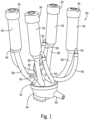
- a traditional milker unit 30 having a teat cup 32, a teat cup liner 34 disposed in the teat cup 32, a short milk tube 38 joined to or formed integrally with the teat cup liner 34, a milking claw 42, and milk bowl 44 at its downstream end.
- a teat cup 32, liner 34, and short milk tube 38 for each teat of the dairy animal.
- the milking claw 42 and milk bowl 44 collect milk from all short milk tubes 38.
- the objective of the milker unit 30 is to draw milk away from the dairy animal teats, out of a milk bowl outlet 39, and into the central dairy milk lines (not illustrated), reduce the amount of milk flowing back toward the teat, and reduce the amount of air drawn into the central dairy milk line when vacuum is being applied.
- a dairy animal teat is inserted through an upper orifice of the teat cup liner 34.
- a constant vacuum is applied inside the milker unit 30 to attach the liner 34 and teat cup 32 to the teat and then draw milk through the liner 34, the short milk tube 38, the milking claw 42 and the bowl 44, and out of the milk bowl outlet 39.
- the weight of the milker unit 30 is supported by the teats because of the constant vacuum being applied inside the milker unit 30.
- the teat cup 32 (sometimes referred to in the art as a "shell") is a relatively rigid cup typically made of stainless steel or other suitable material.
- the teat cup liner 34 is disposed inside the teat cup 32, and a pulsation chamber is defined in the space between the teat cup 32 and the liner 34.
- a pulsating vacuum is applied through a short pulse tube 50 that extends between a short pulse nipple 54 and a short pulsation connection 56 on the milking claw 42.
- a long pulsation hose (not illustrated) connects to a long pulsation hose nipple 58 on the milking claw 42.
- a hanger 60 is also provided on the milking claw 42 to support the milker unit 30 from a milker unit detacher mechanism (not illustrated) when not milking.
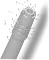
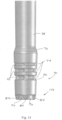
- the short milk tube 38 of the present invention includes a wall 62 having an outer wall surface 64 and an inner wall surface 66 defining a milk passage 68.
- the milk passage 68 has as an upstream direction toward the liner 34 and a downstream direction toward the milking claw 42.
- the short milk tube further includes; a downstream milk claw connection end 70 and a position and release device 72 joined to and extending away from the downstream milk claw connection end 70.
- the short milk tube 38 also includes a controlled flexible portion 74 disposed in the upstream direction from the position and release device 72, a reinforced portion 76 disposed in the upstream direction from the controlled flexible portion 74, and an interior milking claw inlet sealing surface 78 disposed on the inner wall surface 66.
- the milker unit 30 When the milker unit 30 is attached to an animal in a "milking position" ( Fig. 2 ), the milker unit 30 is essentially a closed system and there is relatively little stress on the short milk tube.
- the milker unit 30 When the milker unit 30 is released from an animal, the teat cup 32 and the liner 34 drop downward and the short milk tube 38 bends over into a "standby position" ( Fig. 3 ).
- the bending of the short milk tube 38 essentially kinks the short milk tube 38 against the milking claw inlet 46 to prevent air from entering the now open end of the teat cup liner 34.
- the milking claw inlet 46 is made of stainless steel and is tapered, so a relatively aggressive edge engages the inner wall surface of the bent portion of the short milk tube 38.
- the short milk tube 38 of the present invention resists wear by including the reinforced portion 76 adjacent to and upstream from the milking claw inlet 46 so that it engages the inlet 46 when the short milk tube 38 is properly positioned.
- the kink in the short milk tube 38 permits the interior milking claw inlet sealing surface 78 to seal off the constant vacuum from reaching the open-ended teat cup liner 34 and undesirably drawing air into the central dairy milk line.
- the controlled flexible portion 74 is disposed adjacent to and downstream from the reinforced portion 76 to enhance and control the direction and degree of bending to optimize contact between the interior milking claw inlet sealing surface 78 and the milking claw inlet 46.
- the controlled flexible portion 74 preferably includes at least a portion of an annular groove 90 ( Fig. 5 ) extending at least part way around the wall of the short milk tube 38, and more preferably includes a plurality of annular grooves 90 disposed in the upstream direction from the milking claw contact prongs 84.
- the annular grooves 90 each include a number of ribs 92 to further control the degree and direction of bending.
- the ribs 92 are illustrated extending on a longitudinal direction relative to the short milk tube 38, but other orientations can be used as well.
- the controlled flexible portion 74 can include other wall thickness, groove, rib, and other shapes to control the degree and direction of bending.
- the reinforced portion 76 is illustrated as an area of increased wall thickness and it is preferred that the wall thickness taper in both the upstream direction and the downstream direction, although other shapes can be used and the thickened portion can be replaced or enhanced with other materials or shapes.
- the interior milking claw inlet sealing surface 78 can be part of the inner wall surface 66 or a separate part or a different material joined to the inner wall surface 66. It is also possible that one of the teat cups will drop off from one of the teats before the other teat cups. With a constant vacuum still being applied, the liner 34 will be sealed off by the weight of the teat cup hanging down and kinking the short milk tube 38, so that the amount of air drawn into through the milker unit 30 is minimized.
- the short milk tube 38 of the present invention performs the sealing function efficiently without excessive wear to the inside of the short milk tube 38.
- the reinforced portion 76, the controlled flexible portion 74, and the sealing surface 78 are symmetrical about the longitudinal axis of the short milk tube 38, but asymmetrical features can also be used to provide controlled bending in only one direction, for example.
- the short milk tube 38 can be made of rubber, silicone, or other flexible material to provide the necessary bending and flexibility to move between the milking position ( Fig. 2 ) and the resting/non-milking position ( Fig. 3 ).
- the flexibility at the controlled flexible portion 74 provides these benefits, but to operate properly, it must be positioned accurately on the milking claw inlet 46. For example, if the short milk tube 38 is not pushed far enough onto the inlet 46, the reinforced portion 76 will be above and spaced apart from the inlet 46 and serve no purpose.
- the reinforced portion 76 will also miss the inlet 46 end, and the controlled flexible portion 74 will be too close to the milking claw 42 and be constrained by the milking claw inlet 46.
- the present invention further includes the short milk tube position and release device 72 that provides a visual indication when the short milk tube 38 has been pushed onto the milking claw inlet 46 to the proper extent so that the reinforced portion 76, the interior milking claw inlet sealing surface 78, and the controlled flexible portion 74 are properly positioned relative to the inlet 46. Further, when any or all of the controlled flexible portion 74, the reinforced portion 76, or the sealing surface 78 are asymmetrical as described above, the rotational orientation of the short milk tube 38 would be important, and the position and release device 72 can be used to ensure proper rotational orientation relative to the asymmetrical features.
- the position and release device 72 preferably includes at least one milking claw contact prong 84, and more preferably includes a number of spaced apart milking claw contact prongs 84 extending away from the end of the short milk tube 38 to touch a top face 85 of the milking claw 42 and provide a readily visible indication that the short milk tube 38 has been positioned onto the milking claw inlet 46 when they contact a top surface 85 of the milking claw 42 that is adjacent to the milking claw inlet 46.
- the milking claw contact prongs 84 also provide physical resistance to ensure that the short milk tube 38 has not been pushed too far down the inlet 46. Nonetheless, the milking claw contact prongs 84 are still capable of being compressed for removing the short milk tube 38, as discussed below.
- the milking claw contact prongs 84 are depicted as being uniformly sized and spaced, but different quantities, materials, sizes, spacings, and even colors are also possible, especially when they are used to ensure proper rotational orientation, as described above. It is also possible to include one or more alignment markings on the milking claw top face 85 or other appropriate location for alignment with a contact prong 84 to achieve a predetermined rotational alignment of the short milk tube 38. When multiple milking claw contact prongs 84 are included, it may not be necessary that all of them touch the top face of the milking claw 42 to indicate proper positioning of the short milk tube 38.
- the milking claw contact prongs 84 assist in removing the short milk tube 38 when they must be replaced due to normal wear and tear or other damage. Assistance is useful because the short milk tube 38 has an inlet contact portion 87 (upstream from the position and release device 72 and at least partially downstream from the controlled flexible portion 74) that oftentimes develops a tenacious adherence to the milking claw inlet 46 during normal use. Simply tugging on the short milk tube 38 to separate the two can require considerable force and is actually counterproductive because the adherence to the milking claw inlet 46 causes the short milk tube 38 material to draw down and stretch, which applies an additional normal force on the interface between the inlet contact portion 87 of the short milk tube 38 and the milking claw inlet 46.
- the operator actually pushes the short milk tube 38 toward the milking claw 42 to compress ( Fig. 9 ) or flare ( Fig. 10 ) (or both compress and flare) the milking claw contact prongs 84 against the milking claw 42 top face 85.
- the compressed or flared milking claw contact prongs 84 are a visual indication that the short milk tube 38 can then be more easily pulled from the milking claw inlet 46 because the adherence of the inlet contact portion 87 to the milking claw inlet 46 has been at least partially overcome.
- the adherence is at least partially overcome because the compressed ( Fig. 9 ) or flared ( Fig.
- milking claw prongs 84 also bend or compress the adjacent inlet contact portion 87 of the short milk tube 38 away from the inlet 46 and thereby at least partially break any adherence between the short milk tube 38 and the milk claw inlet 46 as seen in Figs. 9 and 10 .
- the milking claw contact prongs 84 serve to properly position the short milk tube 38 when being installed and to aid in releasing the short milk tube 38 when replacement is required.
- the milking claw contact prongs 84 can be any desired shape or material, but it is preferred to shape them as integrally formed truncated pyramids that are substantially rectangular in cross-section as seen if Fig. 5 , for example, so that they provide progressively more resistance as they are pushed against the milking claw 42.
- Other shapes such as cones, truncated cones, pyramids, cubes, cylinders, and so on, can be used as well. Using such shapes to touch the milk claw top face 85 provides a tactile as well as visual indicator of proper installation of the short milk tube 38.
- Installing the short milk tube using the position and release device 72 includes the steps of pushing the short milk tube 38 onto the milking claw inlet 46 until the position and release device 72 contacts the upper surface 85 of the milking claw 42 to ensure that the controlled flexible portion 74, reinforced portion 76, and the sealing surface 78 are located accurately relative to the end of the milking claw inlet 46. Inaccurately positioning the short milk tube 38 on the milking claw inlet 46 could cause the controlled flexible portion 74, the reinforced portion 76, and the sealing surface 78 not to align with the end of the inlet 46.
- Easier removal of the short milk tube 38 is achieved by a method of first pushing the short milk tube 38 further onto the inlet 46, and compressing the position and release device 72 (contact prongs 84 in the illustrated embodiment) and compressing and bending the adjacent inlet contact portion 87 outwardly from the inlet 46 to thereby at least partially break the bond that may have formed between the inlet contact portion 87 and inlet 46. This then allows significantly less friction when the step of putting the short milk tube 38 under tension (pulling) for removal. is performed.
- protruding positioning prongs 84 act as spacers to guide installation to the optimum extent on the inlet 46 during installation, yet can be easily compressed during the removal procedure to indicate that the bond at the mating interface has been broken before the short milk tube 38 is pulled off.
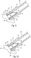
- a second embodiment of the present invention having a teat cup liner 34, a short milk tube 38, and a milk claw connection end 70 with a position and release device 172 as part of the downstream milk claw connection end 70 of the short milk tube 38.
- This embodiment of the position and release device is designated by the reference numeral 172 to distinguish it from the embodiment described above with reference numeral 72.
- the second embodiment of the milk claw connection end 70 also preferably includes the controlled flexible portion 74, a reinforced portion 76, and an interior milk claw inlet sealing surface 78.
- the position and release device 172 of this second embodiment includes the contact prongs 84 to touch and be compressed against a top face 85 of the milking claw 42 (as in Figs. 9 and 10 , for example).
- the contact prongs 84 are spaced apart and form pairs of prongs 84.
- a web 96 is provided extending away from the end of the short milk tube 38 and the web 96 may touch or be spaced apart from the top face 85 of the milking claw 42 when in use.
- the web 96 is preferably attached to and disposed between pairs of the prongs 84 to enable easier release from a forming mold.
- the web 96 is compressible and is preferably formed of the same material as the prongs 84, so that the web 96 is compressible with the prongs 84. Nonetheless, variations in thicknesses and geometry can be used to control the location and degree of compression, if desired.
- the prongs 84 and the webs 96 are preferably uncompressed when the milking operations are being performed.
- the prongs 84 and the webs 96 of the position and release device 172 are compressed against the milking claw 42 top face 85 to at least partially bend the inner inlet contact portion 87 away from the milking claw to aid in releasing the short milk tube 38, as described above.
- the addition of the web 96 can add a degree of resistance to being compressed, but otherwise, the position and release device 172 operates as described above in relation to the embodiment labeled 72.
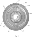
- the web 96 is depicted as a continuous inner ring in Figs. 11 through 14 , but the web 96 could be segmented and may only span between adjacent pairs of the prongs 84 or be present between fewer than all of the pairs of the prongs 84. Further, the web 96 is depicted as being formed integrally with the other elements of the position and release device 172, but all or a portion of the web 96 could be added to the position and release device 172 to provide reinforcement for the prongs 84, for example.
Landscapes
- Life Sciences & Earth Sciences (AREA)
- Animal Husbandry (AREA)
- Environmental Sciences (AREA)
- External Artificial Organs (AREA)
Claims (8)
- Kurzer Milchschlauch (38) einer Melkeinheit, der dazu angepasst ist, auf einer Außenfläche eines Melkzeugeinlasses (46) positioniert zu werden, wobei der kurze Milchschlauch (38) der Melkeinheit Folgendes umfasst:eine Außenwandfläche (64);eine Innenwandfläche (66), die einen Milchdurchgang (68) mit einer Aufwärtsrichtung und einer Abwärtsrichtung definiert; undein stromabwärtiges Melkzeugverbindungsende (70), das eine Positionier-und Freigabevorrichtung (72) umfasst, dadurch gekennzeichnet, dassdie Positionier- und Freigabevorrichtung (72) in Abwärtsrichtung komprimierbar ist, um einen angrenzenden Einlasskontaktabschnitt (87) des kurzen Milchschlauchs (38) nach außen von dem Melkzeugeinlass (46) wegzubiegen, um das Lösen des kurzen Milchschlauchs (38) der Melkeinheit vom Melkzeugeinlass (46) zu unterstützen.
- Kurzer Milchschlauch (38) der Melkeinheit nach Anspruch 1, wobei die Positionier- und Freigabevorrichtung (72) Folgendes umfasst:
ein Paar beabstandeter Melkzeugkontaktzinken (84), die eine unkomprimierte Stellung und eine komprimierte Stellung aufweisen, wobei der Einlasskontaktabschnitt (87) dazu angeordnet ist, den Melkzeugeinlass (46) zu berühren, wenn sich der Einlasskontaktabschnitt (87) in der unkomprimierten Stellung befindet, und zumindest teilweise vom Kontakt gelöst ist, wenn sich die Melkzeugkontaktzinken (84) in der komprimierten Stellung befinden. - Kurzer Milchschlauch (38) der Melkeinheit nach Anspruch 1, wobei die Positionier- und Freigabevorrichtung (72) Folgendes umfasst:
eine Vielzahl von beabstandeten Melkzeugkontaktzinken (84). - Kurzer Milchschlauch (38) der Melkeinheit nach Anspruch 1, wobei die Positionier- und Freigabevorrichtung (72) ein Paar beabstandeter Melkzeugkontaktzinken (84) umfasst, die in Abwärtsrichtung komprimierbar sind, um einen angrenzenden Einlasskontaktabschnitt (87) des kurzen Milchschlauchs (38) während eines Entfernungsvorgangs zu biegen.
- Kurzer Milchschlauch (38) der Melkeinheit nach Anspruch 1, wobei die Positionier- und Freigabevorrichtung (72) eine Melkzeugkontaktzinke (84) als radialen Ausrichtungsindikator umfasst.
- Kurzer Milchschlauch (38) der Melkeinheit nach Anspruch 1, wobei das stromabwärtige Melkzeugverbindungsende (70) ferner umfasst:
einen verstärkten Abschnitt (76), der in Aufwärtsrichtung von der Positionier-und Freigabevorrichtung (72) angeordnet ist. - Kurzer Milchschlauch (38) der Melkeinheit nach Anspruch 1, wobei das stromabwärtige Melkzeugverbindungsende (70) ferner umfasst:einen verstärkten Abschnitt (76), der auf der Außenwandfläche (64) angeordnet ist; undeine innere Melkzeugeinlassdichtungsfläche (78), die im Wesentlichen gegenüber dem verstärkten Abschnitt (76) angeordnet ist.
- Kurzer Milchschlauch (38) der Melkeinheit nach Anspruch 1, wobei der kurze Milchschlauch (38) ferner umfasst:ein stromaufwärtiges Ende; undeine Melkeinheitzitzenbecherhülse (34), die mit dem stromaufwärtigen Ende verbunden ist.
Applications Claiming Priority (3)
| Application Number | Priority Date | Filing Date | Title |
|---|---|---|---|
| US16/544,458 US11516990B2 (en) | 2019-08-19 | 2019-08-19 | Milker unit short milk tube with milk claw end connector |
| US16/946,646 US11632931B2 (en) | 2019-08-19 | 2020-06-30 | Milker unit short milk tube with milk claw end connector |
| PCT/US2020/046668 WO2021034762A1 (en) | 2019-08-19 | 2020-08-17 | Milker unit short milk tube with milk claw end connector |
Publications (2)
| Publication Number | Publication Date |
|---|---|
| EP4017255A1 EP4017255A1 (de) | 2022-06-29 |
| EP4017255B1 true EP4017255B1 (de) | 2024-11-27 |
Family
ID=72340406
Family Applications (1)
| Application Number | Title | Priority Date | Filing Date |
|---|---|---|---|
| EP20765393.2A Active EP4017255B1 (de) | 2019-08-19 | 2020-08-17 | Kurzer milchschlauch für melkeinheit mit milchklauen-endanschluss |
Country Status (7)
| Country | Link |
|---|---|
| US (1) | US11632931B2 (de) |
| EP (1) | EP4017255B1 (de) |
| CN (1) | CN114080153B (de) |
| BR (1) | BR112022003185A2 (de) |
| ES (1) | ES3013930T3 (de) |
| PL (1) | PL4017255T3 (de) |
| WO (1) | WO2021034762A1 (de) |
Families Citing this family (3)
| Publication number | Priority date | Publication date | Assignee | Title |
|---|---|---|---|---|
| IL281971B2 (en) * | 2021-04-01 | 2025-11-01 | Silvianu Ran | Milking machine |
| USD1022350S1 (en) * | 2021-09-22 | 2024-04-09 | Gea Farm Technologies, Inc. | Milker unit short milk tube milk claw end connector |
| USD1057325S1 (en) * | 2022-01-14 | 2025-01-07 | Gea Farm Technologies, Inc. | Short milk tube vent plug for a dairy animal milker unit |
Citations (1)
| Publication number | Priority date | Publication date | Assignee | Title |
|---|---|---|---|---|
| US4196696A (en) * | 1977-02-22 | 1980-04-08 | Alfa-Laval Ab | Shock absorber for teat cup liner |
Family Cites Families (62)
| Publication number | Priority date | Publication date | Assignee | Title |
|---|---|---|---|---|
| US1301992A (en) | 1918-06-05 | 1919-04-29 | Carl Oscar Anderson | Attachment for milking apparatus. |
| US2099884A (en) | 1936-02-26 | 1937-11-23 | Goodrich Co B F | Milking-machine inflation |
| US2341953A (en) | 1942-05-26 | 1944-02-15 | Laval Separator Co De | Milk tube |
| US2513627A (en) | 1947-12-15 | 1950-07-04 | Perfection Mfg Corp | Flow indicator for milking machines |
| DE1011212B (de) | 1956-07-20 | 1957-06-27 | Utina Elektrowerk Gmbh | Zitzengummi fuer Melkbecher |
| US3079891A (en) | 1960-07-25 | 1963-03-05 | Bernard F Miller | Milking cup assembly |
| US3713423A (en) | 1971-01-08 | 1973-01-30 | A Sparr | Udder and teat cleansing apparatus and sanitizer |
| US3967587A (en) | 1972-12-13 | 1976-07-06 | Noorlander Daniel O | Teat cup inflation |
| US4043739A (en) | 1975-04-21 | 1977-08-23 | Kimberly-Clark Corporation | Distributor for thermoplastic extrusion die |
| US3999516A (en) | 1975-06-13 | 1976-12-28 | Babson Brothers Company | Milker with resilient pulsator manifold mounting |
| US4090471A (en) | 1975-06-24 | 1978-05-23 | The United States Of America As Represented By The Secretary Of Agriculture | Short milk tube of a milking machine |
| JPS57500676A (de) | 1980-05-28 | 1982-04-22 | ||
| US4324201A (en) * | 1980-11-13 | 1982-04-13 | Hi-Life Rubber, Inc. | Milking inflation |
| US4530307A (en) | 1982-10-06 | 1985-07-23 | Dec International, Inc. | Teat cup inflation |
| US4745881A (en) | 1986-09-08 | 1988-05-24 | Larson Reed A | Milking inflation |
| NL8700249A (nl) | 1987-02-02 | 1988-09-01 | Multinorm Bv | Werkwijze voor het reinigen van een tepel van een vrouwelijk dier, melkwerkwijze en beker ten gebruike bij bovengenoemde werkwijzen. |
| US4869205A (en) * | 1988-06-03 | 1989-09-26 | Hi-Life Rubber Inc. | Milking machine inflation |
| US5007378A (en) | 1989-03-17 | 1991-04-16 | Hi-Life Rubber Inc. | Milking machine teat cup assembly |
| US5161482A (en) | 1990-06-01 | 1992-11-10 | British Technology Group Limited | Automatic milking apparatus |
| US5482004A (en) | 1994-05-16 | 1996-01-09 | Alfa Laval Agri, Inc. | Collapsible teat liner with reinforced barrel |
| US5493995A (en) | 1994-05-16 | 1996-02-27 | Alfa Laval Agri, Inc. | Collapsing teat cup liner with tapering barrel wall |
| US5572947A (en) | 1995-03-29 | 1996-11-12 | Hi-Life Rubber Inc. | Milking inflation |
| US5752462A (en) | 1995-05-22 | 1998-05-19 | Iba, Inc. | Teat cup inflation |
| US6164243A (en) * | 1998-02-13 | 2000-12-26 | Avon Hi-Life, Inc. | Milking inflation |
| DE69915266T2 (de) * | 1998-03-23 | 2005-03-03 | Silclear Ltd., Lymington | Zitzengummi für eine melkmaschine |
| US6142098A (en) | 1998-05-06 | 2000-11-07 | Maasland N.V. | Teat cup and a milking robot comprising same |
| CN1306389A (zh) | 1998-06-22 | 2001-08-01 | 里博乔有限公司 | 设有清洗装置的挤奶装置 |
| DE19922131C1 (de) | 1999-05-12 | 2001-03-01 | Jakob Maier | Flexibler Milchschlauch für eine automatische Melkanlage |
| US6302058B1 (en) * | 1999-09-27 | 2001-10-16 | North West Environmental Systems, Inc. | Apparatus and method for producing a foam bovine teat dip |
| DE10022716B4 (de) * | 2000-05-10 | 2007-12-13 | Jakob Maier Jun. | Automatische Melkanlage mit Schlauchhülse für einen Melkschlauch |
| NL1015803C2 (nl) | 2000-07-25 | 2002-01-28 | Nedap Nv | Inrichting bestemd voor het injecteren van een flu´dum in een systeem dat een melkbeker en een melkleiding omvat. |
| US6776120B1 (en) | 2002-02-08 | 2004-08-17 | Mofazzal H. Chowdhury | Controlled collapse teatcup liner |
| US6755153B1 (en) | 2002-02-08 | 2004-06-29 | Mofazzal H. Chowdhury | Teatcup liner mouthpiece lip with controlled deflection and slip reduction |
| US6895892B2 (en) | 2002-10-01 | 2005-05-24 | Westfaliasurge, Inc. | Short milk tube |
| US6742475B1 (en) | 2002-12-18 | 2004-06-01 | Delaval Holding Ab | Variable shut off teat cup liner |
| WO2004110134A2 (en) | 2003-06-12 | 2004-12-23 | Avon Polymer Products Limited | Fluid handling assemblies |
| SE525896C2 (sv) | 2003-08-26 | 2005-05-24 | Delaval Holding Ab | Rörformig slanganordning |
| SE527508C2 (sv) | 2004-06-10 | 2006-03-28 | Delaval Holding Ab | Spengummi och spenkopp |
| US8117989B2 (en) | 2008-06-27 | 2012-02-21 | Gea Farm Technologies, Inc. | Milk tube dome with flow controller |
| US8033247B2 (en) | 2004-06-12 | 2011-10-11 | Gea Farm Technologies, Inc. | Automatic dairy animal milker unit backflusher and teat dip applicator system and method |
| US7401573B2 (en) | 2004-06-12 | 2008-07-22 | Westfaliasurge, Inc. | Liner contact automatic teat dip applicator |
| US7290498B2 (en) * | 2004-06-29 | 2007-11-06 | Lauren Agrisystems, Ltd. | Vent plug for milking liner |
| US7293527B2 (en) * | 2004-06-29 | 2007-11-13 | Lauren Agrisystems, Ltd. | Vent plug for milking liner |
| CA2570327C (en) | 2004-06-29 | 2013-11-26 | Lauren Agrisystems, Ltd. | Milking liner |
| NL1032434C2 (nl) * | 2006-09-05 | 2008-03-06 | Maasland Nv | Melkinrichting. |
| US7882803B2 (en) | 2006-09-22 | 2011-02-08 | Lennart Petersson | Teat cup inflation |
| DE102007022800A1 (de) | 2007-05-11 | 2008-11-13 | Westfaliasurge Gmbh | Verbindung von Zitzengummi und Melkbecherhülse |
| ES2643168T3 (es) | 2007-05-11 | 2017-11-21 | Gea Farm Technologies Gmbh | Ordeño de animales con carga reducida de los pezones |
| US8113145B2 (en) * | 2007-09-27 | 2012-02-14 | Gea Farm Technologies, Inc. | Teat cup liner |
| GB0810192D0 (en) | 2008-06-04 | 2008-07-09 | Parker Ind Design Sarl | Milking system |
| US8770146B2 (en) * | 2009-09-04 | 2014-07-08 | Gea Farm Technologies, Inc. | Methods and apparatus for applying teat dip to a dairy animal |
| USD624715S1 (en) | 2009-11-10 | 2010-09-28 | Gea Farm Technologies Gmbh | Milking machine |
| US8375894B2 (en) * | 2010-07-15 | 2013-02-19 | Mofazzal H. Chowdhury | Teatcup liner series with varying mouthpiece flexibility |
| US8567346B1 (en) * | 2012-05-07 | 2013-10-29 | Delaval Holding Ab | Teatcup liner |
| GB201213232D0 (en) * | 2012-07-25 | 2012-09-05 | An Udder Company Ltd | Milking cluster |
| US9288962B2 (en) | 2012-11-02 | 2016-03-22 | Steven Brent Priest | Low-slip high-capacity teat cup liner |
| US9439391B2 (en) * | 2012-12-07 | 2016-09-13 | Lauren Agrisystems, Ltd. | Dairy milking devices and methods |
| NZ706814A (en) | 2012-12-19 | 2018-03-23 | Delaval Holding Ab | A milk conduit, a milk conduit device, a milk-receiving member and a milking member |
| US9408367B2 (en) | 2013-10-28 | 2016-08-09 | Delaval Holding Ab | Teatcup liner with enhanced teat massage |
| WO2016073861A1 (en) | 2014-11-07 | 2016-05-12 | Gea Farm Technologies, Inc. | Short milk tube with protective vent for a dairy animal milker unit |
| DE102015111476B3 (de) | 2015-07-15 | 2016-07-21 | Gea Farm Technologies Gmbh | Zitzengummi mit flexibler Kopfgeometrie |
| CN206895455U (zh) * | 2017-07-10 | 2018-01-19 | 北京京鹏环宇畜牧科技股份有限公司 | 用于牛挤奶平台的可伸缩奶管单元 |
-
2020
- 2020-06-30 US US16/946,646 patent/US11632931B2/en active Active
- 2020-08-17 PL PL20765393.2T patent/PL4017255T3/pl unknown
- 2020-08-17 BR BR112022003185A patent/BR112022003185A2/pt unknown
- 2020-08-17 WO PCT/US2020/046668 patent/WO2021034762A1/en not_active Ceased
- 2020-08-17 ES ES20765393T patent/ES3013930T3/es active Active
- 2020-08-17 EP EP20765393.2A patent/EP4017255B1/de active Active
- 2020-08-17 CN CN202080049019.9A patent/CN114080153B/zh active Active
Patent Citations (1)
| Publication number | Priority date | Publication date | Assignee | Title |
|---|---|---|---|---|
| US4196696A (en) * | 1977-02-22 | 1980-04-08 | Alfa-Laval Ab | Shock absorber for teat cup liner |
Also Published As
| Publication number | Publication date |
|---|---|
| CN114080153B (zh) | 2023-10-10 |
| ES3013930T3 (en) | 2025-04-15 |
| WO2021034762A1 (en) | 2021-02-25 |
| BR112022003185A2 (pt) | 2022-05-17 |
| US11632931B2 (en) | 2023-04-25 |
| EP4017255A1 (de) | 2022-06-29 |
| US20210051912A1 (en) | 2021-02-25 |
| PL4017255T3 (pl) | 2025-09-08 |
| CN114080153A (zh) | 2022-02-22 |
Similar Documents
| Publication | Publication Date | Title |
|---|---|---|
| US11516990B2 (en) | Milker unit short milk tube with milk claw end connector | |
| EP4017255B1 (de) | Kurzer milchschlauch für melkeinheit mit milchklauen-endanschluss | |
| EP1065923B1 (de) | Zitzengummi für eine melkmaschine | |
| EP1549134B1 (de) | Kurzer melkschlauch | |
| CA1289502C (en) | Milking inflation | |
| US20140123903A1 (en) | Low-slip high-capacity teat cup liner | |
| US8627785B2 (en) | Mouthpiece-vented teat cup inflation | |
| CA2415502C (en) | Variable shut off teat cup liner | |
| US6895891B2 (en) | Tube sleeve for a milking tube | |
| US12178185B2 (en) | Short milk tube vent plug for a dairy animal milker unit | |
| EP2934100B1 (de) | Milchleitung und melkelement | |
| EP2020847B1 (de) | Melkbecher | |
| EP2793559B1 (de) | Kartusche und melkbecher | |
| RU2818806C2 (ru) | Молочная трубка блока доильного аппарата с концевым соединителем для молочного коллектора | |
| SE530943C2 (sv) | Spengummi | |
| EP1624745B1 (de) | Zitzengummi | |
| WO2025136186A1 (en) | Teatcup | |
| JP2019092447A (ja) | 結束具および搾乳ユニット | |
| WO2025136187A1 (en) | Teatcup |
Legal Events
| Date | Code | Title | Description |
|---|---|---|---|
| STAA | Information on the status of an ep patent application or granted ep patent |
Free format text: STATUS: UNKNOWN |
|
| STAA | Information on the status of an ep patent application or granted ep patent |
Free format text: STATUS: THE INTERNATIONAL PUBLICATION HAS BEEN MADE |
|
| PUAI | Public reference made under article 153(3) epc to a published international application that has entered the european phase |
Free format text: ORIGINAL CODE: 0009012 |
|
| STAA | Information on the status of an ep patent application or granted ep patent |
Free format text: STATUS: REQUEST FOR EXAMINATION WAS MADE |
|
| 17P | Request for examination filed |
Effective date: 20220304 |
|
| AK | Designated contracting states |
Kind code of ref document: A1 Designated state(s): AL AT BE BG CH CY CZ DE DK EE ES FI FR GB GR HR HU IE IS IT LI LT LU LV MC MK MT NL NO PL PT RO RS SE SI SK SM TR |
|
| DAV | Request for validation of the european patent (deleted) | ||
| DAX | Request for extension of the european patent (deleted) | ||
| STAA | Information on the status of an ep patent application or granted ep patent |
Free format text: STATUS: EXAMINATION IS IN PROGRESS |
|
| 17Q | First examination report despatched |
Effective date: 20240318 |
|
| GRAP | Despatch of communication of intention to grant a patent |
Free format text: ORIGINAL CODE: EPIDOSNIGR1 |
|
| STAA | Information on the status of an ep patent application or granted ep patent |
Free format text: STATUS: GRANT OF PATENT IS INTENDED |
|
| INTG | Intention to grant announced |
Effective date: 20240905 |
|
| GRAS | Grant fee paid |
Free format text: ORIGINAL CODE: EPIDOSNIGR3 |
|
| GRAA | (expected) grant |
Free format text: ORIGINAL CODE: 0009210 |
|
| STAA | Information on the status of an ep patent application or granted ep patent |
Free format text: STATUS: THE PATENT HAS BEEN GRANTED |
|
| AK | Designated contracting states |
Kind code of ref document: B1 Designated state(s): AL AT BE BG CH CY CZ DE DK EE ES FI FR GB GR HR HU IE IS IT LI LT LU LV MC MK MT NL NO PL PT RO RS SE SI SK SM TR |
|
| REG | Reference to a national code |
Ref country code: GB Ref legal event code: FG4D |
|
| REG | Reference to a national code |
Ref country code: CH Ref legal event code: EP |
|
| REG | Reference to a national code |
Ref country code: IE Ref legal event code: FG4D |
|
| REG | Reference to a national code |
Ref country code: DE Ref legal event code: R096 Ref document number: 602020042089 Country of ref document: DE |
|
| REG | Reference to a national code |
Ref country code: LT Ref legal event code: MG9D |
|
| REG | Reference to a national code |
Ref country code: NL Ref legal event code: MP Effective date: 20241127 |
|
| PG25 | Lapsed in a contracting state [announced via postgrant information from national office to epo] |
Ref country code: PT Free format text: LAPSE BECAUSE OF FAILURE TO SUBMIT A TRANSLATION OF THE DESCRIPTION OR TO PAY THE FEE WITHIN THE PRESCRIBED TIME-LIMIT Effective date: 20250327 Ref country code: IS Free format text: LAPSE BECAUSE OF FAILURE TO SUBMIT A TRANSLATION OF THE DESCRIPTION OR TO PAY THE FEE WITHIN THE PRESCRIBED TIME-LIMIT Effective date: 20250327 Ref country code: HR Free format text: LAPSE BECAUSE OF FAILURE TO SUBMIT A TRANSLATION OF THE DESCRIPTION OR TO PAY THE FEE WITHIN THE PRESCRIBED TIME-LIMIT Effective date: 20241127 |
|
| PG25 | Lapsed in a contracting state [announced via postgrant information from national office to epo] |
Ref country code: NL Free format text: LAPSE BECAUSE OF FAILURE TO SUBMIT A TRANSLATION OF THE DESCRIPTION OR TO PAY THE FEE WITHIN THE PRESCRIBED TIME-LIMIT Effective date: 20241127 Ref country code: FI Free format text: LAPSE BECAUSE OF FAILURE TO SUBMIT A TRANSLATION OF THE DESCRIPTION OR TO PAY THE FEE WITHIN THE PRESCRIBED TIME-LIMIT Effective date: 20241127 |
|
| REG | Reference to a national code |
Ref country code: AT Ref legal event code: MK05 Ref document number: 1744763 Country of ref document: AT Kind code of ref document: T Effective date: 20241127 Ref country code: ES Ref legal event code: FG2A Ref document number: 3013930 Country of ref document: ES Kind code of ref document: T3 Effective date: 20250415 |
|
| PG25 | Lapsed in a contracting state [announced via postgrant information from national office to epo] |
Ref country code: BG Free format text: LAPSE BECAUSE OF FAILURE TO SUBMIT A TRANSLATION OF THE DESCRIPTION OR TO PAY THE FEE WITHIN THE PRESCRIBED TIME-LIMIT Effective date: 20241127 |
|
| PG25 | Lapsed in a contracting state [announced via postgrant information from national office to epo] |
Ref country code: NO Free format text: LAPSE BECAUSE OF FAILURE TO SUBMIT A TRANSLATION OF THE DESCRIPTION OR TO PAY THE FEE WITHIN THE PRESCRIBED TIME-LIMIT Effective date: 20250227 |
|
| PG25 | Lapsed in a contracting state [announced via postgrant information from national office to epo] |
Ref country code: GR Free format text: LAPSE BECAUSE OF FAILURE TO SUBMIT A TRANSLATION OF THE DESCRIPTION OR TO PAY THE FEE WITHIN THE PRESCRIBED TIME-LIMIT Effective date: 20250228 Ref country code: AT Free format text: LAPSE BECAUSE OF FAILURE TO SUBMIT A TRANSLATION OF THE DESCRIPTION OR TO PAY THE FEE WITHIN THE PRESCRIBED TIME-LIMIT Effective date: 20241127 Ref country code: LV Free format text: LAPSE BECAUSE OF FAILURE TO SUBMIT A TRANSLATION OF THE DESCRIPTION OR TO PAY THE FEE WITHIN THE PRESCRIBED TIME-LIMIT Effective date: 20241127 |
|
| PG25 | Lapsed in a contracting state [announced via postgrant information from national office to epo] |
Ref country code: RS Free format text: LAPSE BECAUSE OF FAILURE TO SUBMIT A TRANSLATION OF THE DESCRIPTION OR TO PAY THE FEE WITHIN THE PRESCRIBED TIME-LIMIT Effective date: 20250227 |
|
| PG25 | Lapsed in a contracting state [announced via postgrant information from national office to epo] |
Ref country code: SM Free format text: LAPSE BECAUSE OF FAILURE TO SUBMIT A TRANSLATION OF THE DESCRIPTION OR TO PAY THE FEE WITHIN THE PRESCRIBED TIME-LIMIT Effective date: 20241127 |
|
| PG25 | Lapsed in a contracting state [announced via postgrant information from national office to epo] |
Ref country code: DK Free format text: LAPSE BECAUSE OF FAILURE TO SUBMIT A TRANSLATION OF THE DESCRIPTION OR TO PAY THE FEE WITHIN THE PRESCRIBED TIME-LIMIT Effective date: 20241127 |
|
| PG25 | Lapsed in a contracting state [announced via postgrant information from national office to epo] |
Ref country code: EE Free format text: LAPSE BECAUSE OF FAILURE TO SUBMIT A TRANSLATION OF THE DESCRIPTION OR TO PAY THE FEE WITHIN THE PRESCRIBED TIME-LIMIT Effective date: 20241127 |
|
| PG25 | Lapsed in a contracting state [announced via postgrant information from national office to epo] |
Ref country code: RO Free format text: LAPSE BECAUSE OF FAILURE TO SUBMIT A TRANSLATION OF THE DESCRIPTION OR TO PAY THE FEE WITHIN THE PRESCRIBED TIME-LIMIT Effective date: 20241127 |
|
| PG25 | Lapsed in a contracting state [announced via postgrant information from national office to epo] |
Ref country code: SK Free format text: LAPSE BECAUSE OF FAILURE TO SUBMIT A TRANSLATION OF THE DESCRIPTION OR TO PAY THE FEE WITHIN THE PRESCRIBED TIME-LIMIT Effective date: 20241127 |
|
| PG25 | Lapsed in a contracting state [announced via postgrant information from national office to epo] |
Ref country code: CZ Free format text: LAPSE BECAUSE OF FAILURE TO SUBMIT A TRANSLATION OF THE DESCRIPTION OR TO PAY THE FEE WITHIN THE PRESCRIBED TIME-LIMIT Effective date: 20241127 |
|
| REG | Reference to a national code |
Ref country code: DE Ref legal event code: R097 Ref document number: 602020042089 Country of ref document: DE |
|
| PG25 | Lapsed in a contracting state [announced via postgrant information from national office to epo] |
Ref country code: SE Free format text: LAPSE BECAUSE OF FAILURE TO SUBMIT A TRANSLATION OF THE DESCRIPTION OR TO PAY THE FEE WITHIN THE PRESCRIBED TIME-LIMIT Effective date: 20241127 |
|
| PLBE | No opposition filed within time limit |
Free format text: ORIGINAL CODE: 0009261 |
|
| STAA | Information on the status of an ep patent application or granted ep patent |
Free format text: STATUS: NO OPPOSITION FILED WITHIN TIME LIMIT |
|
| PGFP | Annual fee paid to national office [announced via postgrant information from national office to epo] |
Ref country code: ES Payment date: 20250902 Year of fee payment: 6 |
|
| PGFP | Annual fee paid to national office [announced via postgrant information from national office to epo] |
Ref country code: DE Payment date: 20250828 Year of fee payment: 6 |
|
| PGFP | Annual fee paid to national office [announced via postgrant information from national office to epo] |
Ref country code: PL Payment date: 20250821 Year of fee payment: 6 Ref country code: IT Payment date: 20250827 Year of fee payment: 6 |
|
| 26N | No opposition filed |
Effective date: 20250828 |