EP4016793B1 - Verfahren zur implementierung der temperaturregelung für ein drahtloses ladesystem - Google Patents
Verfahren zur implementierung der temperaturregelung für ein drahtloses ladesystem Download PDFInfo
- Publication number
- EP4016793B1 EP4016793B1 EP20895132.7A EP20895132A EP4016793B1 EP 4016793 B1 EP4016793 B1 EP 4016793B1 EP 20895132 A EP20895132 A EP 20895132A EP 4016793 B1 EP4016793 B1 EP 4016793B1
- Authority
- EP
- European Patent Office
- Prior art keywords
- wireless charging
- charging system
- transmitting end
- power
- temperature control
- Prior art date
- Legal status (The legal status is an assumption and is not a legal conclusion. Google has not performed a legal analysis and makes no representation as to the accuracy of the status listed.)
- Active
Links
Images
Classifications
-
- H—ELECTRICITY
- H02—GENERATION; CONVERSION OR DISTRIBUTION OF ELECTRIC POWER
- H02J—CIRCUIT ARRANGEMENTS OR SYSTEMS FOR SUPPLYING OR DISTRIBUTING ELECTRIC POWER; SYSTEMS FOR STORING ELECTRIC ENERGY
- H02J50/00—Circuit arrangements or systems for wireless supply or distribution of electric power
- H02J50/80—Circuit arrangements or systems for wireless supply or distribution of electric power involving the exchange of data, concerning supply or distribution of electric power, between transmitting devices and receiving devices
-
- H—ELECTRICITY
- H02—GENERATION; CONVERSION OR DISTRIBUTION OF ELECTRIC POWER
- H02J—CIRCUIT ARRANGEMENTS OR SYSTEMS FOR SUPPLYING OR DISTRIBUTING ELECTRIC POWER; SYSTEMS FOR STORING ELECTRIC ENERGY
- H02J50/00—Circuit arrangements or systems for wireless supply or distribution of electric power
- H02J50/90—Circuit arrangements or systems for wireless supply or distribution of electric power involving detection or optimisation of position, e.g. alignment
Definitions
- the present disclosure relates to the field of energy transmission, and in particular, to the field of wireless charging, and specifically refers to a method for implementing temperature control for a wireless charging system.
- Wireless charging is a technology using electromagnetic fields or electromagnetic waves for energy transmission.
- a transmitting end will adjust an output power according to a data packet sent by a receiving end to meet requirements of the receiving end.
- KR 20180064741 A discloses that the maximum transmission distance of wireless power transmission via the magnetic induction method is 1 centimeter or less
- WO 2018/212499 A1 discloses that in an electromagnetic resonance scheme, a magnetic field generated by a transmission coil of a wireless power transmitter is tuned to a specific resonance frequency to transmit power to a wireless power receiver located in close proximity
- US 2013/307348 A1 discloses that electromagnetic induction works on the principle of a primary coil generating a predominantly magnetic field and a secondary coil being within that field so that a current is induced in the secondary, as the distance from the primary is increased, more and more of the magnetic field misses the secondary, even over a relatively short range the induction method is rather inefficient, wasting much of the transmitted energy, and the main drawback to wireless transmission is short range.
- Qi as the technical specification of a system for inductive charging that uses the protocol established by the Wireless Power Consortium (WPC), discloses that the distance from the secondary coil to the primary coil should be in a range of 4-5 mm.
- WPC Wireless Power Consortium
- the objective of the present disclosure is to overcome the above-mentioned shortcomings in the prior art and provide a method for implementing temperature control for a wireless charging system, which achieves a good effect, is easy to operate, and has a wide application range.
- the method for implementing temperature control for a wireless charging system in the present disclosure is as follows:
- the method for implementing temperature control for a wireless charging system includes the following steps:
- step (3) specifically includes the following steps:
- the adjusting, by the transmitting end, the operating frequency specifically includes the following steps: reducing, by the transmitting end, the received power of the receiving end.
- the reducing, by the transmitting end, the received power of the receiving end specifically includes the following steps: adjusting, by the transmitting end, the operating frequency through a fixed negative value to reduce the received power of the receiving end.
- the method further includes a step of setting the power loss threshold, which specifically includes the following steps:
- the adjusting of the position of the wireless charging system in step (1.1) specifically includes the following operation: adjusting an offset position of the wireless charging system with a vertical distance unchanged.
- the initial value of the power control flag is 0.
- the flag value of the power control flag is 1.
- the preset test time in step (1.1) is 20 minutes.
- the preset temperature in step (1.1) is 60 °C.
- the method for implementing temperature control for a wireless charging system in the present disclosure solves the problem that the charging current of the transmitting end is excessively large and the temperature of the board components of the transmitting end is excessively high when the wireless charging system works at a relatively remote position, causing burnout of the components.
- heating of the components of the transmitting end can be effectively reduced, and normal and stable operation of the system can be ensured.
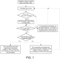
- Fig. 1 is a flowchart of a method for implementing temperature control for a wireless charging system in the present disclosure.
- the method for implementing temperature control for a wireless charging system in the present disclosure includes the following steps:
- the initial value of the power control flag is 0.
- the flag value of the power control flag is 1.
- the preset test time in step (1.1) is 20 minutes.
- the preset temperature in step (1.1) is 60 °C.
- the present disclosure solves the problem that when a wireless charging system works at a far distance (about 20 mm) and has a relatively large position offset during working, that is, a horizontal offset distance between a center position of the transmitting end coil and a center position of a receiving end coil is about 15 mm to 20 mm, long-time working of the wireless charging system causes an excessively large charging current of the transmitting end and overheating of the board components. As a result, the components are burned out, and the system cannot work normally.
- the wireless charging transmitting end reduces heating of the components of the transmitting end by limiting the received power of the receiving end, to ensure normal operation of the wireless charging system.
- FIG. 1 A flowchart for implementing temperature control for a wireless charging system in this embodiment is shown in Fig. 1 :
- the wireless charging system works at each offset position for 20 minutes to test the temperature of the board components of the transmitting end. If the temperature exceeds 60 °C, the value of power loss at the offset position is used as the power loss threshold; otherwise, the system is in a safe state.
- a temperature of MOS transistors of the transmitting end reaches the highest and exceeds 75°C after the wireless charging system works for more than 15 minutes.
- the temperature of the MOS transistors of the transmitting end is lower than 60°C.
- the method for implementing temperature control for a wireless charging system in the present disclosure solves the problem that the charging current of the transmitting end is excessively large and the temperature of the board components of the transmitting end is excessively high when the wireless charging system works at a relatively remote position, causing burnout of the components.
- heating of the components of the transmitting end can be effectively reduced, and normal and stable operation of the system can be ensured.
Landscapes
- Engineering & Computer Science (AREA)
- Computer Networks & Wireless Communication (AREA)
- Power Engineering (AREA)
- Charge And Discharge Circuits For Batteries Or The Like (AREA)
Claims (12)
- Verfahren zum Implementieren einer Temperatursteuerung für ein drahtloses Ladesystem, das die folgenden Schritte umfasst:(1) Initialisieren einer Leistungssteuerungsflag auf einen Startwert;(2) Berechnen, eines Leistungsverlustes durch ein Übertragungsende gemäß einer Übertragungsleistung des Übertragungsendes und einer Empfangsleistung eines Empfangsendes;dadurch gekennzeichnet, dass das Verfahren ferner die folgenden Schritte umfasst:(3.1) Bestimmen durch das Übertragungsende, ob der Leistungsverlust größer als ein voreingestellter Leistungsverlustschwellenwert ist, und wenn dies der Fall ist, Setzen der Leistungssteuerungsflag auf einen Flag-Wert und Durchführen von Schritt (3.2); andernfalls Durchführen von Schritt (3.2); und(3.2) Bestimmen durch das Übertragungsende, ob die Leistungssteuerungsflag der Startwert ist, und wenn dies der Fall ist, Anpassen, der Betriebsfrequenz durch das Übertragungsende gemäß einem tatsächlichen Datenpaket, das mittels des Empfangsendes gesendet wird, und Durchführen von Schritt (2); andernfalls Durchführen von Schritt (5);(5) Bestimmen durch das Übertragungsende, ob ein Wert der Empfangsleistung des Empfangsendes kleiner als ein voreingestellter Empfangsleistungsschwellenwert ist, und wenn dies der Fall ist, Überspringen des Anpassens der Betriebsfrequenz durch das Übertragungsende und Beenden des Schritts; andernfalls Anpassen der Betriebsfrequenz durch das Übertragungsende und Durchführen von Schritt (2).
- Verfahren zum Implementieren einer Temperatursteuerung für ein drahtloses Ladesystem nach Patentanspruch 1, wobei in Schritt (3.2), wenn das Übertragungsende bestimmt, dass die Leistungssteuerungsflag der Startwert ist, das Verfahren insbesondere umfasst:
Anpassen, der Betriebsfrequenz durch das Übertragungsende gemäß dem tatsächlichen Datenpaket, das mittels des Empfangsendes gesendet wird, und Durchführen von Schritt (2). - Verfahren zum Implementieren einer Temperatursteuerung für ein drahtloses Ladesystem nach Patentanspruch 1, wobei das Anpassen der Betriebsfrequenz durch das Übertragungsende insbesondere die folgenden Schritte umfasst:
Reduzieren, der Empfangsleistung des Empfangsendes durch das Übertragungsende. - Verfahren zum Implementieren einer Temperatursteuerung für ein drahtloses Ladesystem nach Patentanspruch 3, wobei das Reduzieren der Empfangsleistung des Empfangsendes durch das Übertragungsende insbesondere die folgenden Schritte umfasst:
Anpassen der Betriebsfrequenz durch das Übertragungsende mittels eines festen negativen Werts, um die Empfangsleistung des Empfangsendes zu reduzieren. - Verfahren zum Implementieren einer Temperatursteuerung für ein drahtloses Ladesystem nach Patentanspruch 1, wobei Schritt (1) ferner einen Schritt des Setzens des Leistungsverlustschwellenwerts umfasst, der insbesondere die folgenden Schritte umfasst:(1.1) Initialisieren der Leistungssteuerungsflag auf den Startwert, Anpassen einer Position des drahtlosen Ladesystems und Erfassen einer Temperatur von Platinenkomponenten des Übertragungsendes, nachdem das drahtlose Ladesystem für eine voreingestellte Testzeit arbeitet; und(1.2) Bestimmen, ob die Temperatur eine voreingestellte Temperatur überschreitet, und wenn dies der Fall ist, Bestimmen, dass ein Wert des Leistungsverlustes an der Position der Leistungsverlustschwellenwert ist; andernfalls Durchführen von Schritt (1.1).
- Verfahren zum Implementieren einer Temperatursteuerung für ein drahtloses Ladesystem nach Patentanspruch 5, wobei in Schritt (1.1) das Anpassen einer Position des drahtlosen Ladesystems insbesondere den folgenden Vorgang umfasst:
Anpassen einer versetzten Position des drahtlosen Ladesystems mit einem unveränderten vertikalen Abstand. - Verfahren zum Implementieren einer Temperatursteuerung für ein drahtloses Ladesystem nach Patentanspruch 6, wobei der vertikale Abstand 18 mm bis 20 mm beträgt.
- Verfahren zum Implementieren einer Temperatursteuerung für ein drahtloses Ladesystem nach Patentanspruch 6, wobei die versetzte Position 18 mm bis 20 mm beträgt.
- Verfahren zum Implementieren einer Temperatursteuerung für ein drahtloses Ladesystem nach Patentanspruch 1, wobei der Startwert der Leistungssteuerungsflag 0 beträgt.
- Verfahren zum Implementieren einer Temperatursteuerung für ein drahtloses Ladesystem nach Patentanspruch 1, wobei der Flag-Wert der Leistungssteuerungsflag 1 beträgt.
- Verfahren zum Implementieren einer Temperatursteuerung für ein drahtloses Ladesystem nach Patentanspruch 5, wobei die voreingestellte Testzeit in Schritt (1.1) 20 Minuten beträgt.
- Verfahren zum Implementieren einer Temperatursteuerung für ein drahtloses Ladesystem nach Patentanspruch 5, wobei die voreingestellte Temperatur in Schritt (1.1) 60 °C beträgt.
Applications Claiming Priority (2)
| Application Number | Priority Date | Filing Date | Title |
|---|---|---|---|
| CN201911221761.9A CN110729808B (zh) | 2019-12-03 | 2019-12-03 | 实现无线充电系统温度控制的方法 |
| PCT/CN2020/133583 WO2021110093A1 (zh) | 2019-12-03 | 2020-12-03 | 实现无线充电系统温度控制的方法 |
Publications (4)
| Publication Number | Publication Date |
|---|---|
| EP4016793A1 EP4016793A1 (de) | 2022-06-22 |
| EP4016793A4 EP4016793A4 (de) | 2023-01-25 |
| EP4016793C0 EP4016793C0 (de) | 2024-10-16 |
| EP4016793B1 true EP4016793B1 (de) | 2024-10-16 |
Family
ID=69226431
Family Applications (1)
| Application Number | Title | Priority Date | Filing Date |
|---|---|---|---|
| EP20895132.7A Active EP4016793B1 (de) | 2019-12-03 | 2020-12-03 | Verfahren zur implementierung der temperaturregelung für ein drahtloses ladesystem |
Country Status (3)
| Country | Link |
|---|---|
| EP (1) | EP4016793B1 (de) |
| CN (1) | CN110729808B (de) |
| WO (1) | WO2021110093A1 (de) |
Families Citing this family (3)
| Publication number | Priority date | Publication date | Assignee | Title |
|---|---|---|---|---|
| CN110729808B (zh) * | 2019-12-03 | 2021-07-23 | 华润微集成电路(无锡)有限公司 | 实现无线充电系统温度控制的方法 |
| CN113258626B (zh) * | 2020-02-12 | 2025-05-23 | 北京小米移动软件有限公司 | 无线充电方法及装置、充电设备及存储介质 |
| CN111586572B (zh) * | 2020-05-29 | 2022-06-03 | 深圳市吉祥腾达科技有限公司 | 一种保证网络设备稳定性的散热方法及系统 |
Family Cites Families (15)
| Publication number | Priority date | Publication date | Assignee | Title |
|---|---|---|---|---|
| US9094110B2 (en) * | 2011-05-27 | 2015-07-28 | uBeam Inc. | Sender transducer for wireless power transfer |
| US9536656B2 (en) * | 2012-05-21 | 2017-01-03 | Texas Instruments Incorporated | Systems and methods of reduction of parasitic losses in a wireless power system |
| US20160164324A1 (en) * | 2013-06-03 | 2016-06-09 | Mediatek Inc. | Portable device capable of controlling output characteristics of adaptor, and corresponding method |
| BR112015024207B1 (pt) * | 2013-07-17 | 2021-10-26 | Koninklijke Philips N.V. | Sistema de transferência de potência sem fio que inclui um transmissor de potência e um receptor de potência, receptor de potência para um sistema de transferência de potência sem fio, e, método de operação de um sistema de transferência de potência sem fio |
| US9793717B2 (en) * | 2013-08-23 | 2017-10-17 | Qualcomm Incorporated | Apparatus and method for non-compliant object detection |
| CN105334539B (zh) * | 2014-06-30 | 2018-09-14 | 无锡华润矽科微电子有限公司 | 无线充电中实现异物检测的方法 |
| TR201902932T4 (tr) * | 2015-07-21 | 2019-03-21 | Koninklijke Philips Nv | Senkronize edilmiş güç ölçümü ile endüktif kablosuz güç aktarımı. |
| TWI574483B (zh) * | 2015-09-21 | 2017-03-11 | 緯創資通股份有限公司 | 無線充電裝置、無線充電盒及其無線充電方法 |
| CN107026516B (zh) * | 2016-02-01 | 2022-04-05 | 恩智浦美国有限公司 | 无线充电系统中的接收机移除检测 |
| KR102633453B1 (ko) * | 2016-12-06 | 2024-02-05 | 엘지이노텍 주식회사 | 이물질 검출 방법 및 그를 위한 장치 |
| KR20180125826A (ko) * | 2017-05-16 | 2018-11-26 | 엘지이노텍 주식회사 | 무선 충전 방법 및 그를 위한 장치 및 시스템 |
| CN107801237A (zh) * | 2017-11-15 | 2018-03-13 | 北京联盛德微电子有限责任公司 | 具备功率控制装置的无线充电系统及功率控制方法 |
| US10784044B2 (en) * | 2018-04-30 | 2020-09-22 | Integrated Device Technology, Inc. | Optimization of transmit and transmit/receive (TRX) coils for wireless transfer of power |
| CN108879887A (zh) * | 2018-08-20 | 2018-11-23 | 广州全界通讯科技有限公司 | 一种无线充电的控制方法、装置、系统及设备 |
| CN110729808B (zh) * | 2019-12-03 | 2021-07-23 | 华润微集成电路(无锡)有限公司 | 实现无线充电系统温度控制的方法 |
-
2019
- 2019-12-03 CN CN201911221761.9A patent/CN110729808B/zh active Active
-
2020
- 2020-12-03 EP EP20895132.7A patent/EP4016793B1/de active Active
- 2020-12-03 WO PCT/CN2020/133583 patent/WO2021110093A1/zh not_active Ceased
Also Published As
| Publication number | Publication date |
|---|---|
| EP4016793A1 (de) | 2022-06-22 |
| WO2021110093A1 (zh) | 2021-06-10 |
| EP4016793C0 (de) | 2024-10-16 |
| CN110729808B (zh) | 2021-07-23 |
| CN110729808A (zh) | 2020-01-24 |
| EP4016793A4 (de) | 2023-01-25 |
Similar Documents
| Publication | Publication Date | Title |
|---|---|---|
| EP4016793B1 (de) | Verfahren zur implementierung der temperaturregelung für ein drahtloses ladesystem | |
| CN110168855B (zh) | 无线充电装置和无线充电方法 | |
| KR101831993B1 (ko) | 무선 전력 수신기의 충전 전류를 제어하기 위한 장치 및 방법 | |
| US9680335B2 (en) | Apparatus for transmitting and receiving wireless power | |
| CN104124775A (zh) | 无线电能传输系统及其智能控制方法、智能控制系统 | |
| MY166584A (en) | Method and arrangement for uplink power control | |
| RU2011109020A (ru) | Способ и устройство для автоматического регулирования параметров, чтобы компенсировать саморегулирующуюся мощность передачи и уровень чувствительности в узле-в | |
| KR20150056345A (ko) | 무선 전력 전송 시스템에서 전력 제어 방법 및 장치 | |
| RU2637499C1 (ru) | Способ беспроводной передачи электрической энергии | |
| KR102409276B1 (ko) | 무선 전력 전송 장치를 포함하는 마우스 패드 및 무선 전력 전송 시스템 | |
| WO2019122937A3 (en) | Monitoring system | |
| CN114302488B (zh) | 设备的标识设置方法、主机、从机、主从机系统及介质 | |
| US9787128B2 (en) | Wireless charger and wireless charging method | |
| CN102932894A (zh) | 一种控制射频输出功率的通信系统及方法 | |
| WO2014176872A1 (zh) | 无线电能传输系统的功率调节方法及系统 | |
| CN101465678A (zh) | 一种用于wlan系统中的发射功率自动控制方法 | |
| CN111600367A (zh) | 无线充电中的发射频率控制方法、装置及相关设备 | |
| CN100440752C (zh) | 实现目标信噪比快速收敛的发射功率控制方法 | |
| US11942792B2 (en) | Apparatus and methods for inverter mode switching in wireless charging transmitters | |
| CN111669811B (zh) | 一种低功耗无线发射机及其发射功率控制方法 | |
| CN102573037A (zh) | 终端内的抗干扰方法和终端设备 | |
| WO2021182817A3 (ko) | 무선전력 전송장치, 무선전력 수신장치 및 이들에 의한 통신 방법 | |
| CN106376072A (zh) | 3g模块发射功率控制系统及其控制方法 | |
| CN116193554A (zh) | 功率控制方法、装置及相关设备 | |
| CN108173361A (zh) | 无线供配电插座最大传输效率匹配传输距离系统及方法 |
Legal Events
| Date | Code | Title | Description |
|---|---|---|---|
| STAA | Information on the status of an ep patent application or granted ep patent |
Free format text: STATUS: THE INTERNATIONAL PUBLICATION HAS BEEN MADE |
|
| PUAI | Public reference made under article 153(3) epc to a published international application that has entered the european phase |
Free format text: ORIGINAL CODE: 0009012 |
|
| STAA | Information on the status of an ep patent application or granted ep patent |
Free format text: STATUS: REQUEST FOR EXAMINATION WAS MADE |
|
| 17P | Request for examination filed |
Effective date: 20220316 |
|
| AK | Designated contracting states |
Kind code of ref document: A1 Designated state(s): AL AT BE BG CH CY CZ DE DK EE ES FI FR GB GR HR HU IE IS IT LI LT LU LV MC MK MT NL NO PL PT RO RS SE SI SK SM TR |
|
| A4 | Supplementary search report drawn up and despatched |
Effective date: 20221222 |
|
| RIC1 | Information provided on ipc code assigned before grant |
Ipc: H02J 50/80 20160101ALI20221216BHEP Ipc: H02J 7/02 20160101ALI20221216BHEP Ipc: H02J 7/04 20060101AFI20221216BHEP |
|
| DAV | Request for validation of the european patent (deleted) | ||
| DAX | Request for extension of the european patent (deleted) | ||
| STAA | Information on the status of an ep patent application or granted ep patent |
Free format text: STATUS: EXAMINATION IS IN PROGRESS |
|
| 17Q | First examination report despatched |
Effective date: 20231207 |
|
| GRAP | Despatch of communication of intention to grant a patent |
Free format text: ORIGINAL CODE: EPIDOSNIGR1 |
|
| STAA | Information on the status of an ep patent application or granted ep patent |
Free format text: STATUS: GRANT OF PATENT IS INTENDED |
|
| INTG | Intention to grant announced |
Effective date: 20240522 |
|
| GRAS | Grant fee paid |
Free format text: ORIGINAL CODE: EPIDOSNIGR3 |
|
| GRAA | (expected) grant |
Free format text: ORIGINAL CODE: 0009210 |
|
| STAA | Information on the status of an ep patent application or granted ep patent |
Free format text: STATUS: THE PATENT HAS BEEN GRANTED |
|
| AK | Designated contracting states |
Kind code of ref document: B1 Designated state(s): AL AT BE BG CH CY CZ DE DK EE ES FI FR GB GR HR HU IE IS IT LI LT LU LV MC MK MT NL NO PL PT RO RS SE SI SK SM TR |
|
| REG | Reference to a national code |
Ref country code: GB Ref legal event code: FG4D |
|
| REG | Reference to a national code |
Ref country code: DE Ref legal event code: R096 Ref document number: 602020039720 Country of ref document: DE Ref country code: CH Ref legal event code: EP |
|
| REG | Reference to a national code |
Ref country code: IE Ref legal event code: FG4D |
|
| U01 | Request for unitary effect filed |
Effective date: 20241107 |
|
| U07 | Unitary effect registered |
Designated state(s): AT BE BG DE DK EE FI FR IT LT LU LV MT NL PT RO SE SI Effective date: 20241115 |
|
| U20 | Renewal fee for the european patent with unitary effect paid |
Year of fee payment: 5 Effective date: 20241125 |
|
| PG25 | Lapsed in a contracting state [announced via postgrant information from national office to epo] |
Ref country code: IS Free format text: LAPSE BECAUSE OF FAILURE TO SUBMIT A TRANSLATION OF THE DESCRIPTION OR TO PAY THE FEE WITHIN THE PRESCRIBED TIME-LIMIT Effective date: 20250216 Ref country code: HR Free format text: LAPSE BECAUSE OF FAILURE TO SUBMIT A TRANSLATION OF THE DESCRIPTION OR TO PAY THE FEE WITHIN THE PRESCRIBED TIME-LIMIT Effective date: 20241016 |
|
| PG25 | Lapsed in a contracting state [announced via postgrant information from national office to epo] |
Ref country code: ES Free format text: LAPSE BECAUSE OF FAILURE TO SUBMIT A TRANSLATION OF THE DESCRIPTION OR TO PAY THE FEE WITHIN THE PRESCRIBED TIME-LIMIT Effective date: 20241016 |
|
| PG25 | Lapsed in a contracting state [announced via postgrant information from national office to epo] |
Ref country code: NO Free format text: LAPSE BECAUSE OF FAILURE TO SUBMIT A TRANSLATION OF THE DESCRIPTION OR TO PAY THE FEE WITHIN THE PRESCRIBED TIME-LIMIT Effective date: 20250116 |
|
| PG25 | Lapsed in a contracting state [announced via postgrant information from national office to epo] |
Ref country code: GR Free format text: LAPSE BECAUSE OF FAILURE TO SUBMIT A TRANSLATION OF THE DESCRIPTION OR TO PAY THE FEE WITHIN THE PRESCRIBED TIME-LIMIT Effective date: 20250117 |
|
| PG25 | Lapsed in a contracting state [announced via postgrant information from national office to epo] |
Ref country code: PL Free format text: LAPSE BECAUSE OF FAILURE TO SUBMIT A TRANSLATION OF THE DESCRIPTION OR TO PAY THE FEE WITHIN THE PRESCRIBED TIME-LIMIT Effective date: 20241016 |
|
| PG25 | Lapsed in a contracting state [announced via postgrant information from national office to epo] |
Ref country code: RS Free format text: LAPSE BECAUSE OF FAILURE TO SUBMIT A TRANSLATION OF THE DESCRIPTION OR TO PAY THE FEE WITHIN THE PRESCRIBED TIME-LIMIT Effective date: 20250116 |
|
| PG25 | Lapsed in a contracting state [announced via postgrant information from national office to epo] |
Ref country code: SM Free format text: LAPSE BECAUSE OF FAILURE TO SUBMIT A TRANSLATION OF THE DESCRIPTION OR TO PAY THE FEE WITHIN THE PRESCRIBED TIME-LIMIT Effective date: 20241016 |
|
| PG25 | Lapsed in a contracting state [announced via postgrant information from national office to epo] |
Ref country code: MC Free format text: LAPSE BECAUSE OF FAILURE TO SUBMIT A TRANSLATION OF THE DESCRIPTION OR TO PAY THE FEE WITHIN THE PRESCRIBED TIME-LIMIT Effective date: 20241016 |
|
| PG25 | Lapsed in a contracting state [announced via postgrant information from national office to epo] |
Ref country code: SK Free format text: LAPSE BECAUSE OF FAILURE TO SUBMIT A TRANSLATION OF THE DESCRIPTION OR TO PAY THE FEE WITHIN THE PRESCRIBED TIME-LIMIT Effective date: 20241016 |
|
| PG25 | Lapsed in a contracting state [announced via postgrant information from national office to epo] |
Ref country code: CZ Free format text: LAPSE BECAUSE OF FAILURE TO SUBMIT A TRANSLATION OF THE DESCRIPTION OR TO PAY THE FEE WITHIN THE PRESCRIBED TIME-LIMIT Effective date: 20241016 |
|
| REG | Reference to a national code |
Ref country code: CH Ref legal event code: PL |
|
| PLBE | No opposition filed within time limit |
Free format text: ORIGINAL CODE: 0009261 |
|
| STAA | Information on the status of an ep patent application or granted ep patent |
Free format text: STATUS: NO OPPOSITION FILED WITHIN TIME LIMIT |
|
| 26N | No opposition filed |
Effective date: 20250717 |
|
| GBPC | Gb: european patent ceased through non-payment of renewal fee |
Effective date: 20250116 |
|
| PG25 | Lapsed in a contracting state [announced via postgrant information from national office to epo] |
Ref country code: GB Free format text: LAPSE BECAUSE OF NON-PAYMENT OF DUE FEES Effective date: 20250116 |
|
| PG25 | Lapsed in a contracting state [announced via postgrant information from national office to epo] |
Ref country code: CH Free format text: LAPSE BECAUSE OF NON-PAYMENT OF DUE FEES Effective date: 20241231 |
|
| PG25 | Lapsed in a contracting state [announced via postgrant information from national office to epo] |
Ref country code: IE Free format text: LAPSE BECAUSE OF NON-PAYMENT OF DUE FEES Effective date: 20241203 |