EP4016618B1 - Verpackung für leistungsvorrichtungen - Google Patents
Verpackung für leistungsvorrichtungen Download PDFInfo
- Publication number
- EP4016618B1 EP4016618B1 EP20216024.8A EP20216024A EP4016618B1 EP 4016618 B1 EP4016618 B1 EP 4016618B1 EP 20216024 A EP20216024 A EP 20216024A EP 4016618 B1 EP4016618 B1 EP 4016618B1
- Authority
- EP
- European Patent Office
- Prior art keywords
- layer
- device package
- top layer
- semiconductor device
- semiconductor
- Prior art date
- Legal status (The legal status is an assumption and is not a legal conclusion. Google has not performed a legal analysis and makes no representation as to the accuracy of the status listed.)
- Active
Links
Images
Classifications
-
- H10W70/614—
-
- H10W40/22—
-
- H10W70/05—
-
- H10W70/685—
-
- H10W90/00—
-
- H10W70/611—
-
- H10W70/692—
-
- H10W72/00—
-
- H10W72/884—
-
- H10W90/401—
-
- H10W90/753—
-
- H10W90/754—
-
- H10W90/764—
-
- H10W90/766—
Definitions
- the present disclosure is concerned with a packaging for power semiconductor devices of a power module and a method of forming the packaging.
- Power modules comprising semiconductor devices or dies are used in many fields for e.g. converting or distributing electrical energy. Power modules find application in e.g. consumer and industrial applications, in the automotive industry, aeronautical fields and other areas. Such modules include semiconductor dies that perform e.g. switching or capacitive functions or as rectifiers or the like. A semiconductor die is configured to conduct a load current along a load current path between die terminals. To allow the semiconductor die to be assembled into a practical module, it needs to be provided in a package so that it can be coupled to other parts or components.
- semiconductor die packaging involves mounting the die onto a substrate surface and to provide bonding wires to provide an electrical connection between the die terminals and connectors.
- WBG Wide Band Gap
- Such conventional wire-bonded packaging limits the degree to which dies can be paralleled and gives rise to asymmetries in power loop inductance i.e. can result in parasitic asymmetries.
- These conventional packages therefore do not allow the full benefits of e.g. WBG devices to be exploited.
- An alternative solution that overcomes the parasitic asymmetry problems of conventional packaging, is to use relatively new technique that allow multilayer substrates to be formed, whereby the dies are formed in a top or bottom layer of the structure and connector an insulator layers are also provided. Whilst such multilayer structures provide improvements over conventional packaging in terms of inductance and providing higher symmetry for paralleled WBG devices, they have a higher thermal impedance than such conventional packages. Heat cannot, therefore, be dissipated as effectively with such multilayer packages. Prior art packages are known for example from US2017171978 , US8617927 and US2019378786 .
- a semiconductor device package as defined by claim 1.
- One or more bus bar components and/or pcbs may be mounted on the top layer on a side away from the intermediate layer.
- a plurality of semiconductor dies may be arranged in a parallel pattern.
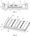
- the semiconductor components 1 are mounted on an upper substrate layer 10 by means of a bonding material 3
- the upper substrate layer 10 is mounted to a lower substrate layer 20 via an intermediate insulating substrate layer 2.
- the resulting package is mounted to a base plate 4 by means of the bonding material 3.
- Wire bonds 5 are provided between the semiconductor components 1 and from the components 1 to connector terminals etc. and the device is mounted in a housing or case 7 made of e.g. plastic.
- a potting or encapsulating material 6 can be provided over the components and substrate layers to protect the device parts and provide an integral device package.
- the base plate acts as a heat sink and may be provided with coolant to improve thermal dissipation.
- cooling plates can be provided on both sides of the package.
- the components may be mounted on a bottom substrate layer and heat could be dissipated through the upper layer.
- Such conventional packaging structures have a high technological maturity and can be quickly and easily manufactured at low cost. As mentioned above, however, such structures are limited as regards parasitic symmetry control.
- the type of packaging materials used in conventional packaging are usually limited to a temperature range of around 150 to 175 deg. C.
- Multilayer substrate structures in which the semiconductor components are formed in the top or bottom layer of the structure better allow components to be paralleled without the problems or parasitic asymmetries.
- the semiconductor layers are usually bonded to the top layer of the multilayer substrate and heat is transported through the bottom layer.
- a copper layer provides the electrical connections.
- Such structures however, have a much higher thermal impedance than wire-bonded structures.
- the structure of the present disclosure aims to use a multilayer substrate structure to achieve the benefits of paralleling and reduced parasitic asymmetries but to retain the thermal advantages of wire-bonded structures.
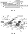
- the semiconductor dies 30 are embedded into a layer 40 of the multilayer structure intermediate the top 60 and bottom 70, or base plate, layer, thus reducing heat flow resistance to the bottom, heat dissipating base layer 70.
- the device includes four parallel semiconductor dies 30 embedded into the intermediate layer 40. This is just by means of example and any type of or number of dies may be provided in any desired pattern.
- the intermediate layer 40 is bonded to a bottom layer or base plate 70 e.g. by welding or solder 45 or other bonding material or process.
- a top layer 60 is mounted over the intermediate layer 40 and bonded thereto e.g. by solder 65 or other bonding material.
- the layers are mounted to a base plate 70 to which they are secured by e.g. welding, solder 45 or other bonding material or process.
- the intermediate layer 40 has a sandwich structure of ceramic layers 56, 57 separated by an intermediate copper or other conductive layer 55.
- the component 30 is embedded in the intermediate ceramic layer and is bonded to the intermediate copper layer 55.
- an interconnect 58 can be formed from the intermediate copper layer on which the component is mounted, through the ceramic layer 56.
- the source is connected to the pcb via a source interconnect 59 directly connected to the component source.
- these interconnects 58, 59 are provided by means of copper or other conductive clips 100 that pass through the top layer 60, at one end, to contact the component 30 in the intermediate layer, and, at the other end, connect with devices or components on the top layer of the package such as the pcb.
- the use of such a clip reduces loop inductance and can also provide better thermal extraction on the top side of the package as well as at the bottom.
- connections between the layers may be more complex than conventional multilayer substrate structures where the components are mounted on the top layer, the use of additive manufacturing techniques can greatly simplify this and so the complexity does not provide any serious disadvantage. Subtractive manufacturing is also a possibility.
- multilayer substrate design means that dies can be mounted in parallel with a high degree of symmetry which means that a greater number of devices can be utilised in the power module.
- the simple mounting of components such as bus bars avoids the need for complex bus bar design which would otherwise add to the overall size and weight of the package.
- the benefits of multilayer substrates, including increased switching speed and greater component density are thus retained whilst reducing thermal impedance compared to known multilayer designs. Therefore, additional heat conducting components are not required which would otherwise add to the size and weight of the device.
Landscapes
- Engineering & Computer Science (AREA)
- Microelectronics & Electronic Packaging (AREA)
- Power Engineering (AREA)
- Computer Hardware Design (AREA)
- Physics & Mathematics (AREA)
- General Physics & Mathematics (AREA)
- Condensed Matter Physics & Semiconductors (AREA)
- Manufacturing & Machinery (AREA)
- Production Of Multi-Layered Print Wiring Board (AREA)
- Chemical & Material Sciences (AREA)
- Materials Engineering (AREA)
- Ceramic Engineering (AREA)
- Combinations Of Printed Boards (AREA)
Claims (11)
- Verpackung für Halbleitervorrichtungen, umfassend ein mehrschichtiges Substrat, das eine obere Schicht (60), eine untere Schicht (70) und eine zwischen der oberen Schicht und der unteren Schicht liegende Zwischenschicht (40) beinhaltet, und ein oder mehrere Halbleiterchips (30), die in die Zwischenschicht eingebettet sind, und ferner umfassend leitende Verbindungsmittel, um eine leitende Verbindung von dem einen oder den mehreren Chips bereitzustellen, wobei sich die leitenden Verbindungsmittel durch die obere Schicht hindurch erstrecken, um Verbindungsmittel für eine oder mehrere Vorrichtungen bereitzustellen, die auf oder benachbart zu der oberen Schicht montiert sind; ferner dadurch gekennzeichnet, dass die Zwischenschicht eine Keramikschicht (56,57) und eine leitende Schicht (55) beinhaltet, und wobei der eine oder die mehreren Halbleiterchips in die Keramikschicht eingebettet sind und in elektrischem Kontakt mit der leitenden Schicht stehen; und wobei die leitenden Verbindungsmittel eine Klemme (100) aus leitendem Material umfassen, die mit dem einen oder den mehreren Halbleiterchips verbunden ist.
- Verpackung für Halbleitervorrichtungen nach Anspruch 1, wobei die leitende Schicht eine Kupferschicht (55) ist.
- Verpackung für Halbleitervorrichtungen nach Anspruch 1 oder 2, wobei die Klemme aus Kupfer hergestellt ist.
- Verpackung für Halbleitervorrichtungen nach einem der vorhergehenden Ansprüche, ferner umfassend eine oder mehrere Sammelschienenkomponenten (80), die auf der oberen Schicht auf einer von der Zwischenschicht abgewandten Seite montiert sind.
- Verpackung für Halbleitervorrichtungen nach einem der vorhergehenden Ansprüche, ferner umfassend eine oder mehrere Leiterplatten (90), die auf der oberen Schicht auf einer von der Zwischenschicht abgewandten Seite montiert sind.
- Verpackung für Halbleitervorrichtungen nach einem der vorhergehenden Ansprüche, umfassend eine Vielzahl von Halbleiterchips, die in einem parallelen Muster angeordnet ist.
- Verpackung für Halbleitervorrichtungen nach einem der vorhergehenden Ansprüche, wobei die untere Schicht ein Kühlkörper ist.
- Verfahren zum Bilden einer Verpackung für Halbleitervorrichtungen nach einem der vorhergehenden Ansprüche, wobei das Verfahren Einbetten eines oder mehrerer Halbleiterchips in die Keramikschicht, Bereitstellen der oberen Schicht über einer Seite der Keramikschicht und der unteren Schicht über einer gegenüberliegenden Seite der Keramikschicht; Bereitstellen der leitenden Verbindung von dem einen oder den mehreren Chips durch die obere Schicht, um eine Verbindung für eine oder mehrere Vorrichtungen bereitzustellen, die auf oder benachbart zu der oberen Schicht montiert sind, umfasst.
- Verfahren nach Anspruch 8, ferner umfassend Montieren einer oder mehrerer Sammelschienenkomponenten (80) auf der oberen Schicht auf einer von der Zwischenschicht abgewandten Seite.
- Verfahren nach Anspruch 8 oder 9, ferner umfassend Montieren einer oder mehrerer Leiterplatten (90) auf der oberen Schicht auf einer von der Zwischenschicht abgewandten Seite.
- Verfahren nach einem der Ansprüche 8 bis 10, ferner umfassend Bereitstellen einer Vielzahl von Halbleiterchips, die in einem parallelen Muster angeordnet ist.
Priority Applications (2)
| Application Number | Priority Date | Filing Date | Title |
|---|---|---|---|
| EP20216024.8A EP4016618B1 (de) | 2020-12-21 | 2020-12-21 | Verpackung für leistungsvorrichtungen |
| US17/542,645 US11935807B2 (en) | 2020-12-21 | 2021-12-06 | Plurality of dies electrically connected to a printed circuit board by a clip |
Applications Claiming Priority (1)
| Application Number | Priority Date | Filing Date | Title |
|---|---|---|---|
| EP20216024.8A EP4016618B1 (de) | 2020-12-21 | 2020-12-21 | Verpackung für leistungsvorrichtungen |
Publications (2)
| Publication Number | Publication Date |
|---|---|
| EP4016618A1 EP4016618A1 (de) | 2022-06-22 |
| EP4016618B1 true EP4016618B1 (de) | 2025-01-29 |
Family
ID=73856152
Family Applications (1)
| Application Number | Title | Priority Date | Filing Date |
|---|---|---|---|
| EP20216024.8A Active EP4016618B1 (de) | 2020-12-21 | 2020-12-21 | Verpackung für leistungsvorrichtungen |
Country Status (2)
| Country | Link |
|---|---|
| US (1) | US11935807B2 (de) |
| EP (1) | EP4016618B1 (de) |
Families Citing this family (2)
| Publication number | Priority date | Publication date | Assignee | Title |
|---|---|---|---|---|
| US11817750B2 (en) * | 2021-01-14 | 2023-11-14 | GM Global Technology Operations LLC | Planar power module with high power density packaging |
| US12538428B2 (en) | 2023-01-24 | 2026-01-27 | Simmonds Precision Products, Inc. | Electrical circuit board assemblies |
Family Cites Families (18)
| Publication number | Priority date | Publication date | Assignee | Title |
|---|---|---|---|---|
| EP0597144A1 (de) * | 1992-11-12 | 1994-05-18 | IXYS Semiconductor GmbH | Hybride leistungselektronische Anordnung |
| US7656677B2 (en) * | 2004-01-27 | 2010-02-02 | Murata Manufacturing Co., Ltd. | Multilayer electronic component and structure for mounting multilayer electronic component |
| TWI324901B (en) * | 2007-01-08 | 2010-05-11 | Unimicron Technology Corp | Printed circuit board structure integrating electronic components |
| EP3843133A1 (de) * | 2009-05-14 | 2021-06-30 | QUALCOMM Incorporated | System in gehäusen |
| US8617927B1 (en) * | 2011-11-29 | 2013-12-31 | Hrl Laboratories, Llc | Method of mounting electronic chips |
| US8884343B2 (en) | 2012-02-24 | 2014-11-11 | Texas Instruments Incorporated | System in package and method for manufacturing the same |
| US9437516B2 (en) * | 2014-01-07 | 2016-09-06 | Infineon Technologies Austria Ag | Chip-embedded packages with backside die connection |
| WO2015157845A1 (en) | 2014-04-16 | 2015-10-22 | Gan Systems Inc. | Embedded packaging for devices and systems comprising lateral gan power transistors |
| US9701534B2 (en) | 2015-01-28 | 2017-07-11 | STATS ChipPAC Pte. Ltd. | Semiconductor device and method of forming MEMS package |
| US10051742B2 (en) * | 2015-12-10 | 2018-08-14 | Industrial Technology Research Institute | Power module and manufacturing method thereof |
| EP3792960A3 (de) | 2016-04-11 | 2021-06-02 | AT & S Austria Technologie & Systemtechnik Aktiengesellschaft | Serienherstellung von komponententrägern |
| US9966371B1 (en) | 2016-11-04 | 2018-05-08 | General Electric Company | Electronics package having a multi-thickness conductor layer and method of manufacturing thereof |
| DE102016225654A1 (de) * | 2016-12-20 | 2018-06-21 | Robert Bosch Gmbh | Leistungsmodul mit einem in Etagen ausgebildeten Gehäuse |
| DE102017105330B4 (de) | 2017-03-14 | 2020-10-15 | Infineon Technologies Austria Ag | Leistungshalbleiterbauelement-Package und Verfahren zum Einbetten eines Leistungshalbleiter-Dies |
| US10163798B1 (en) * | 2017-12-22 | 2018-12-25 | Intel Corporation | Embedded multi-die interconnect bridge packages with lithotgraphically formed bumps and methods of assembling same |
| US20200235067A1 (en) * | 2019-01-22 | 2020-07-23 | Texas Instruments Incorporated | Electronic device flip chip package with exposed clip |
| US10796998B1 (en) | 2019-04-10 | 2020-10-06 | Gan Systems Inc. | Embedded packaging for high voltage, high temperature operation of power semiconductor devices |
| IT201900006736A1 (it) * | 2019-05-10 | 2020-11-10 | Applied Materials Inc | Procedimenti di fabbricazione di package |
-
2020
- 2020-12-21 EP EP20216024.8A patent/EP4016618B1/de active Active
-
2021
- 2021-12-06 US US17/542,645 patent/US11935807B2/en active Active
Also Published As
| Publication number | Publication date |
|---|---|
| US20220199483A1 (en) | 2022-06-23 |
| EP4016618A1 (de) | 2022-06-22 |
| US11935807B2 (en) | 2024-03-19 |
Similar Documents
| Publication | Publication Date | Title |
|---|---|---|
| US9530707B2 (en) | Semiconductor module | |
| US8654541B2 (en) | Three-dimensional power electronics packages | |
| KR102792173B1 (ko) | 통합형 신호 보드를 구비한 상승된 전력 평면을 갖는 전력 모듈 및 이를 구현하는 방법 | |
| US10483237B2 (en) | Vertically stacked multichip modules | |
| KR102586458B1 (ko) | 반도체 서브 어셈블리 및 반도체 파워 모듈 | |
| JP2014199829A (ja) | 半導体モジュール及びそれを搭載したインバータ | |
| KR20090103600A (ko) | 전력 소자용 기판 및 이를 포함하는 전력 소자 패키지 | |
| KR102490612B1 (ko) | 전력용 반도체 모듈 | |
| US10888036B1 (en) | Thermal management assemblies for electronic assemblies circumferentially mounted on a motor | |
| US20190043799A1 (en) | Package structure and fabricating method thereof | |
| CN113823516A (zh) | 包括散热器和控制电子器件构造的固态开关设备 | |
| US11935807B2 (en) | Plurality of dies electrically connected to a printed circuit board by a clip | |
| EP3506725B1 (de) | Elektronische anordnung mit verbesserter hoher leistungsdichte | |
| KR102829692B1 (ko) | 파워모듈 및 그 제조방법 | |
| US20180040562A1 (en) | Elektronisches modul und verfahren zu seiner herstellung | |
| CN101785104A (zh) | 借助从平面中弯曲出的金属冲压格栅或者冲压弯曲件的模块构建和连接技术 | |
| EP2680305A2 (de) | Halbleitergehäuse | |
| KR102792456B1 (ko) | 파워모듈 및 그 제조방법 | |
| US20240128197A1 (en) | Assemblies with embedded semiconductor device modules and related methods | |
| KR101897304B1 (ko) | 파워 모듈 | |
| TW202332357A (zh) | 功率模組 | |
| KR102843819B1 (ko) | 인쇄 회로 기판을 이용한 내부 연결 구조를 갖는 파워 모듈 | |
| CN218647917U (zh) | 一种功率模块 | |
| CN218647940U (zh) | 一种功率模块 | |
| KR102816896B1 (ko) | 파워모듈 |
Legal Events
| Date | Code | Title | Description |
|---|---|---|---|
| PUAI | Public reference made under article 153(3) epc to a published international application that has entered the european phase |
Free format text: ORIGINAL CODE: 0009012 |
|
| STAA | Information on the status of an ep patent application or granted ep patent |
Free format text: STATUS: THE APPLICATION HAS BEEN PUBLISHED |
|
| AK | Designated contracting states |
Kind code of ref document: A1 Designated state(s): AL AT BE BG CH CY CZ DE DK EE ES FI FR GB GR HR HU IE IS IT LI LT LU LV MC MK MT NL NO PL PT RO RS SE SI SK SM TR |
|
| STAA | Information on the status of an ep patent application or granted ep patent |
Free format text: STATUS: REQUEST FOR EXAMINATION WAS MADE |
|
| 17P | Request for examination filed |
Effective date: 20221221 |
|
| RBV | Designated contracting states (corrected) |
Designated state(s): AL AT BE BG CH CY CZ DE DK EE ES FI FR GB GR HR HU IE IS IT LI LT LU LV MC MK MT NL NO PL PT RO RS SE SI SK SM TR |
|
| GRAP | Despatch of communication of intention to grant a patent |
Free format text: ORIGINAL CODE: EPIDOSNIGR1 |
|
| STAA | Information on the status of an ep patent application or granted ep patent |
Free format text: STATUS: GRANT OF PATENT IS INTENDED |
|
| INTG | Intention to grant announced |
Effective date: 20240813 |
|
| GRAS | Grant fee paid |
Free format text: ORIGINAL CODE: EPIDOSNIGR3 |
|
| GRAA | (expected) grant |
Free format text: ORIGINAL CODE: 0009210 |
|
| STAA | Information on the status of an ep patent application or granted ep patent |
Free format text: STATUS: THE PATENT HAS BEEN GRANTED |
|
| AK | Designated contracting states |
Kind code of ref document: B1 Designated state(s): AL AT BE BG CH CY CZ DE DK EE ES FI FR GB GR HR HU IE IS IT LI LT LU LV MC MK MT NL NO PL PT RO RS SE SI SK SM TR |
|
| REG | Reference to a national code |
Ref country code: GB Ref legal event code: FG4D |
|
| REG | Reference to a national code |
Ref country code: CH Ref legal event code: EP |
|
| REG | Reference to a national code |
Ref country code: DE Ref legal event code: R096 Ref document number: 602020045469 Country of ref document: DE |
|
| REG | Reference to a national code |
Ref country code: IE Ref legal event code: FG4D |
|
| REG | Reference to a national code |
Ref country code: NL Ref legal event code: MP Effective date: 20250129 |
|
| PG25 | Lapsed in a contracting state [announced via postgrant information from national office to epo] |
Ref country code: NL Free format text: LAPSE BECAUSE OF FAILURE TO SUBMIT A TRANSLATION OF THE DESCRIPTION OR TO PAY THE FEE WITHIN THE PRESCRIBED TIME-LIMIT Effective date: 20250129 |
|
| PG25 | Lapsed in a contracting state [announced via postgrant information from national office to epo] |
Ref country code: RS Free format text: LAPSE BECAUSE OF FAILURE TO SUBMIT A TRANSLATION OF THE DESCRIPTION OR TO PAY THE FEE WITHIN THE PRESCRIBED TIME-LIMIT Effective date: 20250429 |
|
| PG25 | Lapsed in a contracting state [announced via postgrant information from national office to epo] |
Ref country code: FI Free format text: LAPSE BECAUSE OF FAILURE TO SUBMIT A TRANSLATION OF THE DESCRIPTION OR TO PAY THE FEE WITHIN THE PRESCRIBED TIME-LIMIT Effective date: 20250129 |
|
| PG25 | Lapsed in a contracting state [announced via postgrant information from national office to epo] |
Ref country code: PL Free format text: LAPSE BECAUSE OF FAILURE TO SUBMIT A TRANSLATION OF THE DESCRIPTION OR TO PAY THE FEE WITHIN THE PRESCRIBED TIME-LIMIT Effective date: 20250129 |
|
| PG25 | Lapsed in a contracting state [announced via postgrant information from national office to epo] |
Ref country code: ES Free format text: LAPSE BECAUSE OF FAILURE TO SUBMIT A TRANSLATION OF THE DESCRIPTION OR TO PAY THE FEE WITHIN THE PRESCRIBED TIME-LIMIT Effective date: 20250129 |
|
| REG | Reference to a national code |
Ref country code: LT Ref legal event code: MG9D |
|
| PG25 | Lapsed in a contracting state [announced via postgrant information from national office to epo] |
Ref country code: IS Free format text: LAPSE BECAUSE OF FAILURE TO SUBMIT A TRANSLATION OF THE DESCRIPTION OR TO PAY THE FEE WITHIN THE PRESCRIBED TIME-LIMIT Effective date: 20250529 Ref country code: NO Free format text: LAPSE BECAUSE OF FAILURE TO SUBMIT A TRANSLATION OF THE DESCRIPTION OR TO PAY THE FEE WITHIN THE PRESCRIBED TIME-LIMIT Effective date: 20250429 |
|
| REG | Reference to a national code |
Ref country code: AT Ref legal event code: MK05 Ref document number: 1764354 Country of ref document: AT Kind code of ref document: T Effective date: 20250129 |
|
| PG25 | Lapsed in a contracting state [announced via postgrant information from national office to epo] |
Ref country code: HR Free format text: LAPSE BECAUSE OF FAILURE TO SUBMIT A TRANSLATION OF THE DESCRIPTION OR TO PAY THE FEE WITHIN THE PRESCRIBED TIME-LIMIT Effective date: 20250129 |
|
| PG25 | Lapsed in a contracting state [announced via postgrant information from national office to epo] |
Ref country code: PT Free format text: LAPSE BECAUSE OF FAILURE TO SUBMIT A TRANSLATION OF THE DESCRIPTION OR TO PAY THE FEE WITHIN THE PRESCRIBED TIME-LIMIT Effective date: 20250529 Ref country code: LV Free format text: LAPSE BECAUSE OF FAILURE TO SUBMIT A TRANSLATION OF THE DESCRIPTION OR TO PAY THE FEE WITHIN THE PRESCRIBED TIME-LIMIT Effective date: 20250129 |
|
| PG25 | Lapsed in a contracting state [announced via postgrant information from national office to epo] |
Ref country code: BG Free format text: LAPSE BECAUSE OF FAILURE TO SUBMIT A TRANSLATION OF THE DESCRIPTION OR TO PAY THE FEE WITHIN THE PRESCRIBED TIME-LIMIT Effective date: 20250129 Ref country code: GR Free format text: LAPSE BECAUSE OF FAILURE TO SUBMIT A TRANSLATION OF THE DESCRIPTION OR TO PAY THE FEE WITHIN THE PRESCRIBED TIME-LIMIT Effective date: 20250430 |
|
| PG25 | Lapsed in a contracting state [announced via postgrant information from national office to epo] |
Ref country code: AT Free format text: LAPSE BECAUSE OF FAILURE TO SUBMIT A TRANSLATION OF THE DESCRIPTION OR TO PAY THE FEE WITHIN THE PRESCRIBED TIME-LIMIT Effective date: 20250129 |
|
| PG25 | Lapsed in a contracting state [announced via postgrant information from national office to epo] |
Ref country code: SE Free format text: LAPSE BECAUSE OF FAILURE TO SUBMIT A TRANSLATION OF THE DESCRIPTION OR TO PAY THE FEE WITHIN THE PRESCRIBED TIME-LIMIT Effective date: 20250129 |
|
| PG25 | Lapsed in a contracting state [announced via postgrant information from national office to epo] |
Ref country code: SM Free format text: LAPSE BECAUSE OF FAILURE TO SUBMIT A TRANSLATION OF THE DESCRIPTION OR TO PAY THE FEE WITHIN THE PRESCRIBED TIME-LIMIT Effective date: 20250129 |
|
| PG25 | Lapsed in a contracting state [announced via postgrant information from national office to epo] |
Ref country code: DK Free format text: LAPSE BECAUSE OF FAILURE TO SUBMIT A TRANSLATION OF THE DESCRIPTION OR TO PAY THE FEE WITHIN THE PRESCRIBED TIME-LIMIT Effective date: 20250129 |
|
| PG25 | Lapsed in a contracting state [announced via postgrant information from national office to epo] |
Ref country code: IT Free format text: LAPSE BECAUSE OF FAILURE TO SUBMIT A TRANSLATION OF THE DESCRIPTION OR TO PAY THE FEE WITHIN THE PRESCRIBED TIME-LIMIT Effective date: 20250129 |
|
| PG25 | Lapsed in a contracting state [announced via postgrant information from national office to epo] |
Ref country code: CZ Free format text: LAPSE BECAUSE OF FAILURE TO SUBMIT A TRANSLATION OF THE DESCRIPTION OR TO PAY THE FEE WITHIN THE PRESCRIBED TIME-LIMIT Effective date: 20250129 Ref country code: EE Free format text: LAPSE BECAUSE OF FAILURE TO SUBMIT A TRANSLATION OF THE DESCRIPTION OR TO PAY THE FEE WITHIN THE PRESCRIBED TIME-LIMIT Effective date: 20250129 |
|
| PG25 | Lapsed in a contracting state [announced via postgrant information from national office to epo] |
Ref country code: RO Free format text: LAPSE BECAUSE OF FAILURE TO SUBMIT A TRANSLATION OF THE DESCRIPTION OR TO PAY THE FEE WITHIN THE PRESCRIBED TIME-LIMIT Effective date: 20250129 |
|
| PG25 | Lapsed in a contracting state [announced via postgrant information from national office to epo] |
Ref country code: SK Free format text: LAPSE BECAUSE OF FAILURE TO SUBMIT A TRANSLATION OF THE DESCRIPTION OR TO PAY THE FEE WITHIN THE PRESCRIBED TIME-LIMIT Effective date: 20250129 |
|
| REG | Reference to a national code |
Ref country code: DE Ref legal event code: R097 Ref document number: 602020045469 Country of ref document: DE |
|
| REG | Reference to a national code |
Ref country code: DE Ref legal event code: R079 Ref document number: 602020045469 Country of ref document: DE Free format text: PREVIOUS MAIN CLASS: H01L0023538000 Ipc: H10W0070600000 |
|
| PLBE | No opposition filed within time limit |
Free format text: ORIGINAL CODE: 0009261 |
|
| STAA | Information on the status of an ep patent application or granted ep patent |
Free format text: STATUS: NO OPPOSITION FILED WITHIN TIME LIMIT |
|
| 26N | No opposition filed |
Effective date: 20251030 |
|
| PGFP | Annual fee paid to national office [announced via postgrant information from national office to epo] |
Ref country code: DE Payment date: 20251126 Year of fee payment: 6 |
|
| PGFP | Annual fee paid to national office [announced via postgrant information from national office to epo] |
Ref country code: GB Payment date: 20251119 Year of fee payment: 6 |
|
| PGFP | Annual fee paid to national office [announced via postgrant information from national office to epo] |
Ref country code: FR Payment date: 20251119 Year of fee payment: 6 |