EP4016484A1 - Steuerungssystem für zugangspunktvorrichtungen - Google Patents
Steuerungssystem für zugangspunktvorrichtungen Download PDFInfo
- Publication number
- EP4016484A1 EP4016484A1 EP20215080.1A EP20215080A EP4016484A1 EP 4016484 A1 EP4016484 A1 EP 4016484A1 EP 20215080 A EP20215080 A EP 20215080A EP 4016484 A1 EP4016484 A1 EP 4016484A1
- Authority
- EP
- European Patent Office
- Prior art keywords
- bus
- peripheral
- time
- devices
- control unit
- Prior art date
- Legal status (The legal status is an assumption and is not a legal conclusion. Google has not performed a legal analysis and makes no representation as to the accuracy of the status listed.)
- Granted
Links
Images


Classifications
-
- G—PHYSICS
- G07—CHECKING-DEVICES
- G07C—TIME OR ATTENDANCE REGISTERS; REGISTERING OR INDICATING THE WORKING OF MACHINES; GENERATING RANDOM NUMBERS; VOTING OR LOTTERY APPARATUS; ARRANGEMENTS, SYSTEMS OR APPARATUS FOR CHECKING NOT PROVIDED FOR ELSEWHERE
- G07C9/00—Individual registration on entry or exit
- G07C9/10—Movable barriers with registering means
-
- H—ELECTRICITY
- H04—ELECTRIC COMMUNICATION TECHNIQUE
- H04J—MULTIPLEX COMMUNICATION
- H04J3/00—Time-division multiplex systems
- H04J3/02—Details
- H04J3/06—Synchronising arrangements
- H04J3/0635—Clock or time synchronisation in a network
- H04J3/0638—Clock or time synchronisation among nodes; Internode synchronisation
- H04J3/0652—Synchronisation among time division multiple access [TDMA] nodes, e.g. time triggered protocol [TTP]
- H04J3/0655—Synchronisation among time division multiple access [TDMA] nodes, e.g. time triggered protocol [TTP] using timestamps
-
- H—ELECTRICITY
- H04—ELECTRIC COMMUNICATION TECHNIQUE
- H04L—TRANSMISSION OF DIGITAL INFORMATION, e.g. TELEGRAPHIC COMMUNICATION
- H04L12/00—Data switching networks
- H04L12/28—Data switching networks characterised by path configuration, e.g. LAN [Local Area Networks] or WAN [Wide Area Networks]
- H04L12/40—Bus networks
- H04L12/403—Bus networks with centralised control, e.g. polling
-
- H—ELECTRICITY
- H04—ELECTRIC COMMUNICATION TECHNIQUE
- H04L—TRANSMISSION OF DIGITAL INFORMATION, e.g. TELEGRAPHIC COMMUNICATION
- H04L7/00—Arrangements for synchronising receiver with transmitter
- H04L7/0008—Synchronisation information channels, e.g. clock distribution lines
-
- G—PHYSICS
- G07—CHECKING-DEVICES
- G07C—TIME OR ATTENDANCE REGISTERS; REGISTERING OR INDICATING THE WORKING OF MACHINES; GENERATING RANDOM NUMBERS; VOTING OR LOTTERY APPARATUS; ARRANGEMENTS, SYSTEMS OR APPARATUS FOR CHECKING NOT PROVIDED FOR ELSEWHERE
- G07C2209/00—Indexing scheme relating to groups G07C9/00 - G07C9/38
- G07C2209/06—Involving synchronization or resynchronization between transmitter and receiver; reordering of codes
-
- G—PHYSICS
- G07—CHECKING-DEVICES
- G07C—TIME OR ATTENDANCE REGISTERS; REGISTERING OR INDICATING THE WORKING OF MACHINES; GENERATING RANDOM NUMBERS; VOTING OR LOTTERY APPARATUS; ARRANGEMENTS, SYSTEMS OR APPARATUS FOR CHECKING NOT PROVIDED FOR ELSEWHERE
- G07C2209/00—Indexing scheme relating to groups G07C9/00 - G07C9/38
- G07C2209/08—With time considerations, e.g. temporary activation, valid time window or time limitations
Definitions
- the invention relates to the sector of automation of doors, gates, and similar barrier devices typically used to close access points, e.g. access gates to garages or, more generally, to delimited areas.
- such units may be, for example, a motor for one leaf of a gate, a motor for the other leaf of the gate, a motor for a garage door, a radio receiver for receiving the requests to open/close the gate and the door from a remote control, key selectors and/or control keypads for operating the motors, safety systems, e.g. photocells or sensitive edges, light and/or acoustic signaling devices.
- the communication between the controller and the peripheral devices takes place using the so-called master/slave technique, in which the master is the controller and the slaves are the peripheral devices.
- This technique provides that any command or status information traveling on the bus is handled by the controller.
- the peripheral devices can occupy the bus only following a request sent by the controller itself, in the form of a query or command, to each device. If it is a command, e.g. such as a command to actuate a motor to open a gate, the device will respond by confirming, i.e. with an acknowledge signal. If it is a request for status, e.g. concerning the possible presence of an obstacle that interrupts the light beam of a photocell, the device will respond by sending the requested status information directly.
- a communication protocol thus requires each peripheral device to be associated with an address that the controller uses to identify the recipient of its message, either commands or status requests, and that no device can speak unless it is addressed by the controller.
- bus systems in which instead of following the querying of each device, the master/slave communicates a status by sending a request valid for all devices to which each device responds in separate time windows to avoid clashes on the bus and allow the master to recognize the device that provided such a response.
- the address function is replaced by assigning predefined response time delays for each device relative to the status request.
- peripheral devices can only send data on the bus after a request from the master, which is common for all devices in this case.
- Such a request is generally a pulse with a given coding that the devices recognize as a status request or as a command acknowledgment and from which they calculate a response time, different for each device. Any jitter on the pulse sent by the master thus affects the time windows in which the peripheral devices are allowed to talk. Furthermore, if for any reason the pulse is either not generated or correctly transmitted on the bus, i.e. the communication between master and devices fails, and the communication between devices and master also fails. This prevents the communication of possible alarm states coming from photocell or sensitive edge safety devices which require a prompt intervention on the movement of a barrier, for example.
- the invention achieves the object with a control system for access point devices, such as gates, doors, mobile barriers, and the like, comprising:
- the peripheral units each comprise a clock device capable of independently measuring the time starting from an initial time reference to define characteristic time windows for each peripheral unit to be used to send signals on the bus and/or enable commands, the control unit being configured to send a synchronism signal to the peripheral units so that all the peripheral units have the same initial time reference, said synchronism signal being asynchronous and not connected to the intervals defined for the transmission on the bus.
- peripheral devices and the control unit can take place in the absence of a request from the controller itself as the peripheral devices are configured to send data on the bus at mutually different absolute time instants.
- Such instants are established during system installation so that by knowing such absolute time instants the controller can always trace back to the source of given data present on the bus. From time to time, the controller synchronizes the clock devices of the peripheral units to ensure that any changes in the time counts of each unit will not affect the communication protocol.
- peripheral units can operate in broadcast mode, i.e. send states in the absence of any request from the control unit, increasing the reliability and safety of the system as a whole.
- the characteristic time window of a peripheral unit is different from the characteristic time window of another peripheral unit of the plurality to avoid collisions on the bus.
- the characteristic time windows of all the peripheral units have the same duration but may have a different offset from the initial time reference.
- the control unit advantageously comprises a memory element for storing the characteristic time windows of each peripheral unit to be able to associate the information received in a broadcast on the bus with the peripheral unit that transmitted it based on the instant of time since said information was received as calculated by the clock device of the central unit.
- At least one of the peripheral units is a photocell safety device comprising an optical transmitter and an optical receiver.
- the safety device determines that when a light beam sent from the optical transmitter to the optical receiver is interrupted by an obstacle and correspondingly transmits a status signal of the optical reception to the control unit.
- the optical transmitter of the safety device transmits a light beam (or infrared or radio depending on the type of device used) only in the characteristic time window of the device (e.g. the same in which the receiver is enabled to transmit status information on the bus), possible errors due to interference between adjacent photocell devices are avoided.
- each safety device is configured to transmit the optical beam in different characteristic windows so that the receiver of one optical transmitter/receiver pair cannot receive light signals from optical transmitters of other pairs.
- the invention relates to a method for managing bus communication between peripheral devices and a controller in control systems for access point devices, such as gates, doors, mobile barriers, and the like, wherein the method comprises:
- the method advantageously provides the step of enabling the transmission of each transmitter in only the time window associated with the device for transmitting status information on the bus to the controller. In this manner, any possible interference is avoided between adjacent devices, increasing the reliability and safety of the system.
- a system for controlling the movement of a movable barrier such as a gate, a barrier, a door, and the like comprises a bus 4 to which a barrier opening/closing movement module 2, a central control module 3, and a photocell safety device 1 are connected.
- the photocell device 1 comprises an optical transmitter 101 and a corresponding optical receiver 101' coupled so that the receiver 101' can detect when the light beam emitted by the transmitter 101 does not reach the receiver 101', e.g. due to the presence of an obstacle between the two.
- the photocell devices are used to signal the presence of a vehicle or person in the immediate vicinity of the barrier to allow the system to act safely.
- the optical transmitter 101 and the optical receiver 101' typically belong to separate devices 11, 11' each having electronics 201, 201' of the interface towards the bus 4.
- the moving module 2 comprising a motor 102, a motor control device 202, and a port 302 for receiving a barrier movement command via the bus 4.
- the central control module 3 comprises a central unit 103, an input 203, and an interface port 303 towards the bus 4.
- the central unit 103 is configured to read barrier movement commands from the input 203 and correspondingly send actuation signals to the motor control device 202 via the bus 4 as well as read the status of the photocell safety device 1 to promptly interrupt the movement of the barrier if the presence of a vehicle is detected, e.g. by obscuring the passage of the light beam from the photo-transmitter 101 to the photo-receiver 101'.
- the communication system 4 may advantageously be a bus communication system with a master/slave type protocol with the central unit 103 being the master, the motor control device 2, and the photocell devices 11, 11' being corresponding slaves that receive commands from, and send states to, said master.
- There can be further slave devices interfaced with the bus e.g. such as further photocell safety devices, sensitive edge devices, foot-operated presence detectors, radar presence detectors, signaling devices, and other devices typical in this type of system.
- the same input 203 of the central unit 3 may be flanked or replaced by a slave type input device interfaced with the central unit 3 through the bus 4, e.g. such as a key switch, a control keypad, a remote control receiver, and similar devices.
- the bus system can advantageously exploit the communication through only two electrical wires according to the teachings of US 7091687 .
- the master sends commands, e.g. to the movement module 2, or status requests, e.g. to the photocell module 1, through messages having a coding which univocally identifies the peripheral device receiving the communication.
- commands e.g. to the movement module 2
- status requests e.g. to the photocell module 1
- the device to which the command is sent will execute the command and send an acknowledge signal to the master accordingly.
- the device to which this request is addressed will directly respond by sending the requested status.
- the photocell devices for example, when queried, will signal the master whether the optical coupling between each transmitter/receiver pair is interrupted or intact.
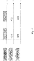
- Fig. 2 shows such a communication protocol in which PKT denotes the packet sent by the master at various instants t i to each of the n devices.
- Fig. 3 shows an alternative communication protocol in which the status request message from the master is one for all slaves according to the teachings of EP 2119125 .
- the drawback of needing to send a status request to each device is avoided in this manner.
- the present invention exploits a similar time-domain multiplexing system to distinguish the origin of status messages but using absolute references, i.e., by having slaves communicate at predetermined times and in predetermined windows in a broadcast mode without waiting for a single or cumulative data request from the master.
- both the control unit 3 and the peripheral units 1 comprise a clock device 301, 301', 402, 403 capable of independently measuring time from an initial time reference to define characteristic time windows for each peripheral unit to be used to send signals on the bus and/or enable commands.
- the control unit 3 is configured to send, from time to time, without a predefined time sequence, and in any case in a manner unrelated to the possible sending of commands or status requests, to the peripheral units 11, 11', 2 a synchronism signal so that all the peripheral units have the same initial time reference.
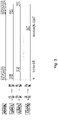
- Fig. 4 shows the typical timing of the system according to an embodiment of the invention.
- Each peripheral device 11, 11', 2 is provided with a clock device 301, 301', 402 that the electronics of the device used to determine the timing of the signals to be sent on the bus to the central unit 3.
- the sending of messages on the communication bus 4 is not affected by any request from the master.
- the timing of the signals is entrusted to clock devices 403, 301, 301', 402 which calculate the time in an absolute manner relative to a synchronization instant which, from time to time, the master sends independently from the request of data sending on the bus to allow the correction of possible time misalignments which may arise during the operation of the system.
- the separation of the messages sent by each device on the bus can take place in broadcast mode or when necessary as long as the device speaks only in the time window assigned to it in the configuration of the system to allow the central unit to discriminate the origin of messages arriving on the bus.
- photocell devices e.g. infrared (IR) photocell devices
- IR infrared
- the receiving photocell i must know when the transmitting photocell i transmits the IR burst, to be sure that the signal it receives at IR level is that of the paired photocell and not of another one.
- the master and the photocells are provided with a timer that runs at the same speed.
- the master occasionally distributes the value of its timer counter to ensure that all the devices are indeed synchronized to the same time value. This means that at the same absolute time, all the timers of the photocells and the master have the same value.
- the timer consists of a 16-bit counter with a granularity of 1 ⁇ s, it will count from value 0 to value 65535 and then start again from 0.
- the TX photocells must transmit, e.g. every 24576 ms (submultiple of 65536), and the photocell with the next index must transmit after 2.5 ms from the previous one, it is possible, for example, to make the photocell with index 0 transmit with offset 0 and the one with index i transmit with offset (2.5 ms x i). In this manner, the RX photocell knows exactly when the TX photocell with the same index must transmit and thus determines whether the IR burst is to be considered or not.
- the central unit 3 For the central unit 3 to be able to establish the time windows associated with each device 1, 2, during system configuration, the number of peripheral units and the relative absolute transmission delay is stored in a memory element 503 associated with the central unit 3, i.e. in practice, in the case of the previous example, the offset values in ms associated with each of the 8 units.
- the invention further relates to a method for configuring a control system for access point devices, such as gates, doors, mobile barriers, and the like of the type described above, which method comprises assigning a fixed enabling time window relative to an absolute time reference to each device and storing said time window in a memory device associated with the central unit so that said central unit can determine from which peripheral device the messages present on the bus originated.
Landscapes
- Engineering & Computer Science (AREA)
- Computer Networks & Wireless Communication (AREA)
- Signal Processing (AREA)
- Physics & Mathematics (AREA)
- General Physics & Mathematics (AREA)
- Small-Scale Networks (AREA)
Priority Applications (1)
| Application Number | Priority Date | Filing Date | Title |
|---|---|---|---|
| EP20215080.1A EP4016484B1 (de) | 2020-12-17 | 2020-12-17 | Steuerungssystem für zugangspunktvorrichtungen |
Applications Claiming Priority (1)
| Application Number | Priority Date | Filing Date | Title |
|---|---|---|---|
| EP20215080.1A EP4016484B1 (de) | 2020-12-17 | 2020-12-17 | Steuerungssystem für zugangspunktvorrichtungen |
Publications (3)
| Publication Number | Publication Date |
|---|---|
| EP4016484A1 true EP4016484A1 (de) | 2022-06-22 |
| EP4016484C0 EP4016484C0 (de) | 2025-12-31 |
| EP4016484B1 EP4016484B1 (de) | 2025-12-31 |
Family
ID=74661214
Family Applications (1)
| Application Number | Title | Priority Date | Filing Date |
|---|---|---|---|
| EP20215080.1A Active EP4016484B1 (de) | 2020-12-17 | 2020-12-17 | Steuerungssystem für zugangspunktvorrichtungen |
Country Status (1)
| Country | Link |
|---|---|
| EP (1) | EP4016484B1 (de) |
Citations (4)
| Publication number | Priority date | Publication date | Assignee | Title |
|---|---|---|---|---|
| US20050055469A1 (en) * | 2003-07-25 | 2005-03-10 | Oliver Scheele | Synchronization of data processing units |
| US7091687B2 (en) | 2002-06-06 | 2006-08-15 | Mhouse Srl | Electrical system for controlling at least one gate or door or similar element of the type moved electrically |
| EP2119125A2 (de) | 2007-02-05 | 2009-11-18 | NICE SpA | Bus-system und zugehöriges übertragungsprotokoll |
| US20150003443A1 (en) * | 2012-03-22 | 2015-01-01 | Bayerische Motoren Werke Aktiengesellschaft | Gateway, Nodes, and Method for a Vehicle |
-
2020
- 2020-12-17 EP EP20215080.1A patent/EP4016484B1/de active Active
Patent Citations (4)
| Publication number | Priority date | Publication date | Assignee | Title |
|---|---|---|---|---|
| US7091687B2 (en) | 2002-06-06 | 2006-08-15 | Mhouse Srl | Electrical system for controlling at least one gate or door or similar element of the type moved electrically |
| US20050055469A1 (en) * | 2003-07-25 | 2005-03-10 | Oliver Scheele | Synchronization of data processing units |
| EP2119125A2 (de) | 2007-02-05 | 2009-11-18 | NICE SpA | Bus-system und zugehöriges übertragungsprotokoll |
| US20150003443A1 (en) * | 2012-03-22 | 2015-01-01 | Bayerische Motoren Werke Aktiengesellschaft | Gateway, Nodes, and Method for a Vehicle |
Also Published As
| Publication number | Publication date |
|---|---|
| EP4016484C0 (de) | 2025-12-31 |
| EP4016484B1 (de) | 2025-12-31 |
Similar Documents
| Publication | Publication Date | Title |
|---|---|---|
| US12143416B2 (en) | Relay-attack resistant communications | |
| US6011821A (en) | Process for synchronization of matching circuits of a communication system with several modules | |
| US4799052A (en) | Method for communicating data on a communication network by token passing | |
| US4945532A (en) | Local network testing using carrier sense multiple access and collision detection (CSMA/CD) | |
| FI73852C (fi) | Kommunikationssystem med kollisionshinder. | |
| JP2600622B2 (ja) | Tdma方式の移動通信システムにおける下り制御信号の送信制御方法 | |
| EP2119125B1 (de) | Bus-system und zugehöriges übertragungsprotokoll | |
| US4837788A (en) | Repeater for extending local area networks | |
| US7291998B2 (en) | Electrical control safety system comprising photocells or equivalent sensors | |
| CN104237962B (zh) | 用于使光电屏障的光学单元同步的方法以及光幕 | |
| US20120239838A1 (en) | Safety Arrangement | |
| EP0081821B1 (de) | System von lokalen Netzen mit Konkurrenzbetrieb | |
| EP4016484B1 (de) | Steuerungssystem für zugangspunktvorrichtungen | |
| CA3006051C (en) | Methods for synchronization pulse control of channel bandwidth on data communication bus | |
| JPH05211511A (ja) | 通信装置 | |
| EP1201055A1 (de) | Verfahren und gerät für drahtlose kommunikation | |
| EP4152699B1 (de) | Erkennung von konfigurationsfehlern in einem bussteuerungssystem | |
| GB2229023A (en) | Controlling remote electrical appliances via the mains supply | |
| EP2117144A1 (de) | Masterloses Zeitmultiplexverfahren zur Übermittlung von Sicherheitszuständen | |
| US20200250123A1 (en) | Systems, apparatuses and methods for dual line inbound detection on a data communication bus | |
| EP4026973A1 (de) | Steuerungssystem für zugangspunktvorrichtungen | |
| JP2618890B2 (ja) | 異常送信検出方式 | |
| US5732625A (en) | Method and system for transmitting signals in a printing machine | |
| RU2789347C1 (ru) | Вычислительная система и способ функционирования вычислительной системы | |
| GB2101457A (en) | Data communication system |
Legal Events
| Date | Code | Title | Description |
|---|---|---|---|
| PUAI | Public reference made under article 153(3) epc to a published international application that has entered the european phase |
Free format text: ORIGINAL CODE: 0009012 |
|
| STAA | Information on the status of an ep patent application or granted ep patent |
Free format text: STATUS: THE APPLICATION HAS BEEN PUBLISHED |
|
| AK | Designated contracting states |
Kind code of ref document: A1 Designated state(s): AL AT BE BG CH CY CZ DE DK EE ES FI FR GB GR HR HU IE IS IT LI LT LU LV MC MK MT NL NO PL PT RO RS SE SI SK SM TR |
|
| STAA | Information on the status of an ep patent application or granted ep patent |
Free format text: STATUS: REQUEST FOR EXAMINATION WAS MADE |
|
| 17P | Request for examination filed |
Effective date: 20221221 |
|
| RBV | Designated contracting states (corrected) |
Designated state(s): AL AT BE BG CH CY CZ DE DK EE ES FI FR GB GR HR HU IE IS IT LI LT LU LV MC MK MT NL NO PL PT RO RS SE SI SK SM TR |
|
| P01 | Opt-out of the competence of the unified patent court (upc) registered |
Effective date: 20230525 |
|
| GRAP | Despatch of communication of intention to grant a patent |
Free format text: ORIGINAL CODE: EPIDOSNIGR1 |
|
| STAA | Information on the status of an ep patent application or granted ep patent |
Free format text: STATUS: GRANT OF PATENT IS INTENDED |
|
| INTG | Intention to grant announced |
Effective date: 20250923 |
|
| GRAS | Grant fee paid |
Free format text: ORIGINAL CODE: EPIDOSNIGR3 |
|
| GRAA | (expected) grant |
Free format text: ORIGINAL CODE: 0009210 |
|
| STAA | Information on the status of an ep patent application or granted ep patent |
Free format text: STATUS: THE PATENT HAS BEEN GRANTED |
|
| AK | Designated contracting states |
Kind code of ref document: B1 Designated state(s): AL AT BE BG CH CY CZ DE DK EE ES FI FR GB GR HR HU IE IS IT LI LT LU LV MC MK MT NL NO PL PT RO RS SE SI SK SM TR |
|
| REG | Reference to a national code |
Ref country code: CH Ref legal event code: F10 Free format text: ST27 STATUS EVENT CODE: U-0-0-F10-F00 (AS PROVIDED BY THE NATIONAL OFFICE) Effective date: 20251231 Ref country code: GB Ref legal event code: FG4D |
|
| REG | Reference to a national code |
Ref country code: DE Ref legal event code: R096 Ref document number: 602020064701 Country of ref document: DE |
|
| REG | Reference to a national code |
Ref country code: IE Ref legal event code: FG4D |
|
| U01 | Request for unitary effect filed |
Effective date: 20260121 |
|
| U07 | Unitary effect registered |
Designated state(s): AT BE BG DE DK EE FI FR IT LT LU LV MT NL PT RO SE SI Effective date: 20260127 |
|
| PG25 | Lapsed in a contracting state [announced via postgrant information from national office to epo] |
Ref country code: NO Free format text: LAPSE BECAUSE OF FAILURE TO SUBMIT A TRANSLATION OF THE DESCRIPTION OR TO PAY THE FEE WITHIN THE PRESCRIBED TIME-LIMIT Effective date: 20260331 |
|
| PG25 | Lapsed in a contracting state [announced via postgrant information from national office to epo] |
Ref country code: HR Free format text: LAPSE BECAUSE OF FAILURE TO SUBMIT A TRANSLATION OF THE DESCRIPTION OR TO PAY THE FEE WITHIN THE PRESCRIBED TIME-LIMIT Effective date: 20251231 |
|
| PG25 | Lapsed in a contracting state [announced via postgrant information from national office to epo] |
Ref country code: RS Free format text: LAPSE BECAUSE OF FAILURE TO SUBMIT A TRANSLATION OF THE DESCRIPTION OR TO PAY THE FEE WITHIN THE PRESCRIBED TIME-LIMIT Effective date: 20260331 |