EP4015711B1 - Holding apparatus and work machine including the same - Google Patents
Holding apparatus and work machine including the same Download PDFInfo
- Publication number
- EP4015711B1 EP4015711B1 EP21209213.4A EP21209213A EP4015711B1 EP 4015711 B1 EP4015711 B1 EP 4015711B1 EP 21209213 A EP21209213 A EP 21209213A EP 4015711 B1 EP4015711 B1 EP 4015711B1
- Authority
- EP
- European Patent Office
- Prior art keywords
- holding
- arm
- pivot
- pair
- opening
- Prior art date
- Legal status (The legal status is an assumption and is not a legal conclusion. Google has not performed a legal analysis and makes no representation as to the accuracy of the status listed.)
- Active
Links
- 230000007246 mechanism Effects 0.000 claims description 53
- 239000000463 material Substances 0.000 claims description 14
- 230000005484 gravity Effects 0.000 claims description 13
- 239000002131 composite material Substances 0.000 claims description 12
- 230000002265 prevention Effects 0.000 claims description 5
- 230000033001 locomotion Effects 0.000 description 54
- 230000036544 posture Effects 0.000 description 46
- 230000008602 contraction Effects 0.000 description 18
- 238000012986 modification Methods 0.000 description 14
- 230000004048 modification Effects 0.000 description 14
- 230000003014 reinforcing effect Effects 0.000 description 12
- 230000001965 increasing effect Effects 0.000 description 6
- 230000000694 effects Effects 0.000 description 5
- 238000003780 insertion Methods 0.000 description 5
- 230000037431 insertion Effects 0.000 description 5
- 210000000078 claw Anatomy 0.000 description 3
- 230000003247 decreasing effect Effects 0.000 description 3
- 239000000470 constituent Substances 0.000 description 2
- 239000007769 metal material Substances 0.000 description 2
- 230000000149 penetrating effect Effects 0.000 description 2
- 230000000452 restraining effect Effects 0.000 description 2
- 238000013519 translation Methods 0.000 description 2
- 238000013459 approach Methods 0.000 description 1
- 239000004567 concrete Substances 0.000 description 1
- 238000013461 design Methods 0.000 description 1
- 230000002708 enhancing effect Effects 0.000 description 1
- 230000002349 favourable effect Effects 0.000 description 1
- 238000009434 installation Methods 0.000 description 1
- 239000011178 precast concrete Substances 0.000 description 1
- 238000009877 rendering Methods 0.000 description 1
- 239000002699 waste material Substances 0.000 description 1
Images


Classifications
-
- E—FIXED CONSTRUCTIONS
- E02—HYDRAULIC ENGINEERING; FOUNDATIONS; SOIL SHIFTING
- E02F—DREDGING; SOIL-SHIFTING
- E02F3/00—Dredgers; Soil-shifting machines
- E02F3/04—Dredgers; Soil-shifting machines mechanically-driven
- E02F3/28—Dredgers; Soil-shifting machines mechanically-driven with digging tools mounted on a dipper- or bucket-arm, i.e. there is either one arm or a pair of arms, e.g. dippers, buckets
- E02F3/36—Component parts
- E02F3/40—Dippers; Buckets ; Grab devices, e.g. manufacturing processes for buckets, form, geometry or material of buckets
- E02F3/402—Dippers; Buckets ; Grab devices, e.g. manufacturing processes for buckets, form, geometry or material of buckets with means for facilitating the loading thereof, e.g. conveyors
- E02F3/404—Dippers; Buckets ; Grab devices, e.g. manufacturing processes for buckets, form, geometry or material of buckets with means for facilitating the loading thereof, e.g. conveyors comprising two parts movable relative to each other, e.g. for gripping
-
- E—FIXED CONSTRUCTIONS
- E02—HYDRAULIC ENGINEERING; FOUNDATIONS; SOIL SHIFTING
- E02F—DREDGING; SOIL-SHIFTING
- E02F3/00—Dredgers; Soil-shifting machines
- E02F3/04—Dredgers; Soil-shifting machines mechanically-driven
- E02F3/28—Dredgers; Soil-shifting machines mechanically-driven with digging tools mounted on a dipper- or bucket-arm, i.e. there is either one arm or a pair of arms, e.g. dippers, buckets
-
- B—PERFORMING OPERATIONS; TRANSPORTING
- B66—HOISTING; LIFTING; HAULING
- B66C—CRANES; LOAD-ENGAGING ELEMENTS OR DEVICES FOR CRANES, CAPSTANS, WINCHES, OR TACKLES
- B66C1/00—Load-engaging elements or devices attached to lifting or lowering gear of cranes or adapted for connection therewith for transmitting lifting forces to articles or groups of articles
- B66C1/10—Load-engaging elements or devices attached to lifting or lowering gear of cranes or adapted for connection therewith for transmitting lifting forces to articles or groups of articles by mechanical means
- B66C1/42—Gripping members engaging only the external or internal surfaces of the articles
- B66C1/44—Gripping members engaging only the external or internal surfaces of the articles and applying frictional forces
- B66C1/54—Internally-expanding grippers for handling hollow articles
-
- B—PERFORMING OPERATIONS; TRANSPORTING
- B66—HOISTING; LIFTING; HAULING
- B66C—CRANES; LOAD-ENGAGING ELEMENTS OR DEVICES FOR CRANES, CAPSTANS, WINCHES, OR TACKLES
- B66C1/00—Load-engaging elements or devices attached to lifting or lowering gear of cranes or adapted for connection therewith for transmitting lifting forces to articles or groups of articles
- B66C1/68—Load-engaging elements or devices attached to lifting or lowering gear of cranes or adapted for connection therewith for transmitting lifting forces to articles or groups of articles mounted on, or guided by, jibs
-
- E—FIXED CONSTRUCTIONS
- E02—HYDRAULIC ENGINEERING; FOUNDATIONS; SOIL SHIFTING
- E02F—DREDGING; SOIL-SHIFTING
- E02F3/00—Dredgers; Soil-shifting machines
- E02F3/04—Dredgers; Soil-shifting machines mechanically-driven
- E02F3/28—Dredgers; Soil-shifting machines mechanically-driven with digging tools mounted on a dipper- or bucket-arm, i.e. there is either one arm or a pair of arms, e.g. dippers, buckets
- E02F3/36—Component parts
- E02F3/42—Drives for dippers, buckets, dipper-arms or bucket-arms
- E02F3/43—Control of dipper or bucket position; Control of sequence of drive operations
-
- E—FIXED CONSTRUCTIONS
- E02—HYDRAULIC ENGINEERING; FOUNDATIONS; SOIL SHIFTING
- E02F—DREDGING; SOIL-SHIFTING
- E02F3/00—Dredgers; Soil-shifting machines
- E02F3/04—Dredgers; Soil-shifting machines mechanically-driven
- E02F3/96—Dredgers; Soil-shifting machines mechanically-driven with arrangements for alternate or simultaneous use of different digging elements
-
- B—PERFORMING OPERATIONS; TRANSPORTING
- B66—HOISTING; LIFTING; HAULING
- B66F—HOISTING, LIFTING, HAULING OR PUSHING, NOT OTHERWISE PROVIDED FOR, e.g. DEVICES WHICH APPLY A LIFTING OR PUSHING FORCE DIRECTLY TO THE SURFACE OF A LOAD
- B66F9/00—Devices for lifting or lowering bulky or heavy goods for loading or unloading purposes
- B66F9/06—Devices for lifting or lowering bulky or heavy goods for loading or unloading purposes movable, with their loads, on wheels or the like, e.g. fork-lift trucks
- B66F9/075—Constructional features or details
- B66F9/12—Platforms; Forks; Other load supporting or gripping members
- B66F9/18—Load gripping or retaining means
Description
- The present invention relates to a holding apparatus provided on a work machine to hold a holding object and relates to a work machine including the holding apparatus.
- Patent Document 1 (
Japanese Unexamined Patent Publication No. 2003-192265 - Patent Document 2 (
Japanese Unexamined Patent Publication No. Sho 61-94991 - Patent Document 3 (
Japanese Unexamined Utility Model Publication No. 59-116459 - Each of devices described in
Patent Document 1 and Patent Document 2, however, is configured to grip an object from the outside of an object, being incapable of holding any object from the inside thereof. On the other hand, the use of the receiving member described in Patent Document 3 for both holding from the outside and holding from the inside requires great change in the posture of the receiving member, which takes time and labor. Besides, both the holding from the outside and the holding from the inside are desired to be performed flexibly in correspondence with the shape of the holding object. - It is an object of the present invention to provide a holding apparatus that is provided on a work machine and capable of both holding a holding object from the outside thereof and holding a holding object from the inside thereof with sufficient holding force flexibly in correspondence with the shape of the holding object, and to provide a work machine including the holding apparatus.
- Provided is a holding apparatus, which is capable of holding a holding object while being connected to a distal end of an attachment body of a work machine comprising the attachment body that has the distal end and is operable to move the distal end, the holding apparatus and the attachment body constituting a work attachment. The holding apparatus includes a holding-apparatus body, a first arm, a second arm, an opening and closing mechanism, a driving device, a first holding element, and a second holding element. The holding-apparatus body is connectable to the distal end of the attachment body. The first arm and the second arm are aligned in an opening and closing direction. Each of the first arm and the second arm includes an arm upper region connected to the holding-apparatus body and an arm lower region extending downward from the arm upper region in a holding posture. The opening and closing mechanism is interposed between the holding-apparatus body and the arm upper region of each of the first arm and the second arm. The opening and closing mechanism connects the arm upper region of each of the first arm and the second arm to the holding-apparatus body so as to allow each of the first arm and the second arm to be translated in the opening and closing direction while keeping the first arm and the second arm in the holding posture to the holding-apparatus body. The holding posture is a posture where the arm lower region extends downward from the arm upper region. The driving device actuates the opening and closing mechanism to change an arm interval. The arm interval is an interval between the first arm and the second arm in the opening and closing direction. The first holding element is connected to the arm lower region of the first arm pivotably around a first holding pivot axis extending in a front-rear direction perpendicular to each of a vertical direction of the holding apparatus and the opening and closing direction. The second holding element is connected to the arm lower region of the second arm pivotably around a second holding pivot axis extending in the front-rear direction. The first holding element and the second holding element have respective inner contact surfaces opposed to each other in the opening and closing direction and respective outer contact surfaces facing opposite sides to the inner contact surfaces, respectively, with respect to the opening and closing direction.
-
-
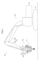
FIG. 1 is a side view of a work machine according to a first embodiment of the present invention. -
FIG. 2 is a front view of a holding apparatus according to the first embodiment, in which the arm interval is small. -
FIG. 3 is a side view of the holding apparatus. -
FIG. 4 is a front view of the holding apparatus, in which the arm interval is large. -
FIG. 5 is a perspective view showing an arm lower region of each of first and second arms in the holding apparatus and each of first and second holding elements connected to the arm lower region. -
FIG. 6 is a perspective view of each of the first and second holding elements. -
FIG. 7 is a front view of a holding apparatus according to a first modification, in which the arm interval is small. -
FIG. 8 is a front view of the holding apparatus according to the first modification, in which the arm interval is large. -
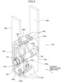
FIG. 9 is a perspective view showing an arm lower region of the holding apparatus according to a second modification and a holding element connected to the arm lower region. -
FIG. 10 is a perspective view showing an arm lower region of the holding apparatus according to the second embodiment of the present invention, and first and second holding elements connected to the arm lower region. -
FIG. 11 is a perspective view showing an arm lower region according to a first modification of the second embodiment, and first and second holding elements connected to the arm lower region. -
FIG. 12 is a perspective view showing an arm lower region according to a second modification of the second embodiment and each of first and second holding elements connected to the arm lower region. -
FIG. 13 is a perspective view of an arm lower region to be compared with the second modification and each of first and second holding elements connected to the arm lower region. -
FIG. 14 is a perspective view showing an arm lower region according to another modification and each of first and second holding elements connected to the arm lower region. - Hereinafter, a preferred embodiment of the present invention will be described with reference to the accompanying drawings.
-
FIG. 1 shows aholding apparatus 10 according to a first embodiment of the present invention and awork machine 100 including theholding apparatus 10. Theholding apparatus 10 is provided to thework machine 100 to hold a carrying object which is a holding object. The holding apparatus is especially suitable for a carrying object which is opened upward. Thework machine 100 includes awork attachment 130 capable of making a work motion. Thework machine 100 illustrated inFIG. 1 is a hydraulic excavator. - The
work machine 100 includes alower traveling body 110, an upper turningbody 120, and thework attachment 130. - The lower traveling
body 110 is capable of making a traveling motion, including, for example, a pair of crawlers. The upper turningbody 120 is mounted on the lower travelingbody 110 so as to be turnable. - The
work attachment 130 is attached to the upper turningbody 120 so as to be movable rotationally vertically. Thework attachment 130 includes anattachment body 132 and atip attachment 134. - The
attachment body 132 includes aboom 136 and anarm 138. Theboom 136 has a proximal end and a distal end opposite thereto. The proximal end is attached to the upper turningbody 120 so as to be movable rotationally vertically. The upper turningbody 120 has a machine right-left direction, which is a direction in which the rotational axis of theboom 136 to the upper turningbody 120 extends. Thearm 138 is attached to the distal end of theboom 136 so as to be movable rotationally vertically. The rotational axis of thearm 138 to theboom 136 extends in the machine right-left direction. - The distal end of the
arm 138 is equivalent to the distal end of theattachment body 132. The distal end of theattachment body 132 can be moved relatively to the upper turningbody 120 by respective rotational movements of theboom 136 and thearm 138. - The
tip attachment 134 is connected to the distal end of thearm 138, i.e., the distal end of theattachment body 132, thus being movable with the distal end. Thetip attachment 134 includes a rotation drive mechanism 140 and the holdingapparatus 10. - The rotation drive mechanism 140 is interposed between the distal end of the
attachment body 132 and the holdingapparatus 10 to rotate the holdingapparatus 10 relatively to theattachment body 132 around a plurality of axes. - The rotation drive mechanism 140 includes a
main body section 142, a tilt section 144, and aturning section 146. - The
main body section 142 is fixed to the distal end of thearm 138, thus being configured to be moved integrally with thearm 138. - The tilt section 144 is interposed between the
main body section 142 and the pair of theturning section 146 and the holdingapparatus 10 to tilt theturning section 146 and the holdingapparatus 10 to themain body section 142, specifically, to move theturning section 146 and the holdingapparatus 10 rotationally around a tilt axis relatively to themain body section 142. The tilt axis extends in a direction perpendicular to the machine right-left direction. The tilt axis is an axis parallel to a plane including an opening and closing direction and the front-rear direction of the holding apparatus 10 (that is, a horizontal plane inFIG. 1 ) as described below in detail. The tilt section 144, thus, can serve as a tilt device that tilts the holdingapparatus 10 to theattachment body 132. - The
turning section 146 is interposed between the tilt section 144 and the holdingapparatus 10 to turn the holdingapparatus 10 around a turning axis relatively to the tilt section 144. The turning axis extends in a turning axis direction. The turning axis direction is a direction perpendicular to each of the opening and closing direction and the front-rear direction of the holdingapparatus 10, namely, a vertical direction inFIG. 1 . The turning axis direction is, in other words, a direction parallel to an attachment direction in which the holdingapparatus 10 is attached to the distal end of theattachment body 132, i.e., the distal end of thearm 138. Theturning section 146 can serve as a turning device that turns the holdingapparatus 10 around the turning axis relatively to theattachment body 132. - The holding
apparatus 10 is capable of holding a holding object while being connected to theattachment body 132 to constitute thework attachment 130. The holding object according to this embodiment is a carryingobject 150 shown inFIG. 2 . The carryingobject 150 has a cross-sectional shape opened upward as described below. - The holding
apparatus 10 is attached to the distal end of theattachment body 132. Specifically, the holdingapparatus 10 according to this embodiment is connected to the distal end of thearm 138 through the rotation drive mechanism 140. The holdingapparatus 10 makes a motion of holding the carryingobject 150, specifically, an opening and closing motion in the opening and closing direction. The opening and closing direction is the right-left direction inFIG. 2 , being a direction perpendicular to the paper surface inFIG. 3 . - As shown in
FIGS. 2 and3 , the holdingapparatus 10 includes abox body 30, abar 40, an opening andclosing mechanism 50, afirst arm 60A, asecond arm 60B, a drivingdevice 70, aninterlock member 80, afirst holding element 90A, and asecond holding element 90B. - The
box body 30 and thebar 40 constitute a holding-apparatus body. The holding-apparatus body supports the first andsecond arms closing mechanism 50 while being connected to theattachment body 132. - The
box body 30 is attachable to the distal end of theattachment body 132. Specifically, thebox body 30 can be connected to the distal end of thearm 138 through the rotation drive mechanism 140, more specifically, can be fixed to theturning section 146 of the rotation drive mechanism 140. - The
box body 30 includes a pair ofside plates 32, atop plate 34, and abottom plate 36. The pair ofside plates 32 are spaced in the front-rear direction and paralleled to each other. The front-rear direction is a direction perpendicular to each of a vertical direction of the holdingapparatus 10 and the opening and closing direction, namely, the right-left direction inFIG. 3 , the direction perpendicular to the paper surface inFIG. 2 . The vertical direction of the holdingapparatus 10 is a direction in which the holding-apparatus body and the first andsecond arms top plate 34 is connected to respective upper ends of the pair ofside plates 32 so as to interconnect the upper ends. Thebottom plate 36 is connected to respective center parts of the lower end of the pair ofside plates 32 so as to interconnect the center parts. The right and left ends of respective lower sides of the pair ofside plates 32 are spaced in the front-rear direction to form respective openings, thereby allowing the below-described movement of the opening andclosing mechanism 50. - The
bar 40 is combined with thebox body 30 to constitute the holding-apparatus body in cooperation with thebox body 30. Thebar 40 has a plate shape extending in a single direction, being fixed to thebox body 30 while penetrating the inside of thebox body 30 in the right-left direction, i.e., the opening and closing direction. Thebar 40 has longitudinally opposite ends, namely, right and left ends, which protrude outward beyond the right and left sides of thebox body 30, respectively. Thebar 40 is fixed to the right-left direction opposite ends of thebox body 30 throughrespective pins FIG. 3 , thepins box body 30 in the front-rear direction (right-left direction inFIG. 3 ) and are fixed to the pair ofside plates 32 of thebox body 30. Thebar 40, thus, can be attached to theattachment body 132 through thebox body 30. - As shown in
FIG. 2 , the first andsecond arms second arms upper region 61 and an armlower region 62. The armupper region 61 extends in the opening and closing direction in the holding posture, being connected to the holding-apparatus body, namely, thebox body 30 and thebar 40 in this embodiment, through the opening andclosing mechanism 50. The armlower region 62 extends downward from the inner end of the armupper region 61 in the holding posture. The inner end is an inner end with respect to the opening and closing direction. The inner end of thefirst arm 60A that is shown on the left side inFIG. 2 is the right end and the inner end of thesecond arm 60B that is shown on the right side is the left end. - Each of the first and
second arms arm plates plate 60c as shown inFIG. 3 . The pair ofarm plates second holding elements FIG. 3 . The reinforcingplate 60c is interposed between the pair ofarm plates FIG. 3 shows only thesecond arm 60B out of the first andsecond arms - The opening and
closing mechanism 50 is interposed between each of thefirst arm 60A and thesecond arm 60B and the holding-apparatus body, namely, thebox body 30 and thebar 40 in this embodiment. The opening andclosing mechanism 50 connectsrespective arm regions 61 of thefirst arm 60A and thesecond arm 60B to the holding-apparatus body so as to allow thefirst arm 60A and thesecond arm 60B to be translated relatively to the holding-apparatus body in the opening and closing direction while being kept in the holding posture. - As shown in
FIG. 2 , the opening andclosing mechanism 50 includes afirst link pair 52A and asecond link pair 52B, which are disposed on the left and right sides, respectively, inFIG. 2 . Thefirst link pair 52A constitutes a parallel-link mechanism in cooperation with the armupper region 61 of thefirst arm 60A and the holding-apparatus body to keep thefirst arm 60A in the holding posture. Similarly, thesecond link pair 52B constitutes a parallel-link mechanism in cooperation with the armupper region 61 of thesecond arm 60B and the holding-apparatus body to keep thesecond arm 60B in the holding posture. - The
first link pair 52A includes a pair of first link members, namely, a firstinner link member 53A and a firstouter link member 54A. The firstinner link member 53A and the firstouter link member 54A are paralleled to each other. - The first
inner link member 53A is disposed on the inner side in the opening and closing direction, i.e., on the side close to the center of the holding-apparatus body with respect to the opening and closing direction, namely, the right side inFIG. 2 . The firstinner link member 53A has an upper end, which is pivotably connected to the left end of thebox body 30 and thebar 40 through thepin 11A. Thepin 11A serves as a first body-side pivot, and the firstinner link member 53A is allowed to pivot around the center axis of thepin 11A to the holding-apparatus body. - The first
outer link member 54A is disposed on the outer side in the opening and closing direction, that is, on the side far from the center of the holding-apparatus body in the opening and closing direction, namely, the left side inFIG. 2 . The firstouter link member 54A has an upper end, which is pivotably connected to one end of thebar 40, namely, the left end inFIG. 2 , through apin 11C. Thepin 11C serves as a first body-side pivot similarly to thepin 11A, and the firstouter link member 54A is allowed to pivot around the center axis of thepin 11C to the holding-apparatus body. - The
second link pair 52B includes a pair of second link members, namely, a secondinner link member 53B and a secondouter link member 54B. The secondinner link member 53B and the secondouter link member 54B are paralleled to each other. - The second
inner link member 53B is disposed on the inner side in the opening and closing direction, i.e., on the side close to the center of the holding-apparatus body with respect to the opening and closing direction, namely, the left side inFIG. 2 . The secondinner link member 53B has an upper part, a slightly lower part than the upper end in this embodiment, which is pivotably connected to the right end of thebox body 30 and thebar 40 through thepin 11B similar to thepin 11A. Thepin 11B serves as a second body-side pivot, and the secondinner link member 53B is allowed to pivot around the center axis of thepin 11B to the holding-apparatus body. - The second
outer link member 54B is disposed on the outer side in the opening and closing direction, that is, on the side far from the center of the holding-apparatus body with respect to the opening and closing direction, namely, the right side inFIG. 2 . The secondouter link member 54B has an upper end, which is connected to the other end of thebar 40, namely, the right end inFIG. 2 , through apin 11D. Thepin 11D serves as a second body-side pivot similarly to thepin 11B, and the secondouter link member 54B is allowed to pivot around the center axis of thepin 11D to the holding-apparatus body. - Each of the first and second
inner link members link plates interconnection member 53c as shown inFIG. 3 . The pair oflink plates FIG. 3 ) and paralleled to each other. Theinterconnection member 53c is interposed between the pair oflink plates FIG. 3 shows only the secondinner link member 53B out of the first and secondinner link members - Similarly, each of the first and second
outer link members link plates interconnection member 54c as shown inFIG. 3 . The pair oflink plates FIG. 3 ) and paralleled to each other. Theinterconnection member 54c is interposed between the pair oflink plates FIG. 3 shows only the secondouter link member 54B out of the first and secondouter link members - The first inner and
outer link members upper region 61 of thefirst arm 60A throughrespective pins pins upper region 61 of thefirst arm 60A, and the lower ends of the first inner andouter linking members pins pin 11E penetrates the inner part of the armupper region 61 with respect to the opening and closing direction, namely, the right part inFIG. 2 , in the front-rear direction, and thepin 11F penetrates the outer part of the armupper region 61 with respect to the opening and closing direction, namely, the left part inFIG. 2 , in the front-rear direction. The first inner andouter link members pins first arm 60A. - The second inner and
outer link members upper region 61 of thesecond arm 60B throughrespective pins pins upper region 61 of thesecond arm 60B, and respective lower ends of the second inner and outer linkingmembers pins pin 11G penetrates the inner part of the armupper region 61 with respect to the opening and closing direction, namely, the left part inFIG. 2 , in the front-rear direction, and thepin 11F penetrates the outer part of the armupper region 61 with respect to the opening and closing direction, namely, the right part inFIG. 2 , in the front-rear direction. The second inner andouter link members pins second arm 60B. - The interval between the
pins pins pins outer link members first arm 60A to be translated in the opening and closing direction relatively to the holding-apparatus body while kept in the holding posture. - Similarly, the interval between the
pins pins pins outer link members second arm 60B to be translated in the opening and closing direction relatively to the holding-apparatus body while being kept in the holding posture. - In this embodiment, as shown in
FIG. 3 , respective upper ends of the pair ofarm plates second arms pins link plates inner link members pins arm plates link plates outer link members pins arm plates - The driving
device 70 actuates the opening andclosing mechanism 50 to change an arm interval. The arm interval is an interval between thefirst arm 60A and thesecond arm 60B in the opening and closing direction. - The driving
device 70 according to this embodiment is composed of a hydraulic cylinder capable of making expansion and contraction motions. The drivingdevice 70 is disposed between the first and second link pairs 52A and 52B so as to cause the first link pair 51 and the second link pair 52 to be rotationally moved in opposite directions along with the expansion and contraction motions. - The hydraulic cylinder constituting the driving
device 70 includes atube 72, apiston 74 and arod 76. Thetube 72 is formed in a cylindrical shape around a center axis and defines a cylinder chamber inside thetube 72. The center axis extends in a cylinder expansion and contraction direction. Thepiston 74 is housed in the cylinder chamber so as to be capable of reciprocating in the cylinder expansion and contraction direction. Therod 76 extends in the cylinder expansion and contraction direction and is integrally joined to thepiston 74 so as to be moved in the cylinder expansion and contraction direction together with thepiston 74 and relatively to thetube 72. The relative movement of therod 76 to thetube 72 in the cylinder expansion and contraction direction expands and contracts the entire hydraulic cylinder in the cylinder expansion and contraction direction. - The driving
device 70 has opposite ends in the cylinder expansion and contraction direction. One of the opposite ends is a rod-side end formed of the distal end of therod 76, and the other of the opposite ends is a bottom-side end formed of an opposite end of thetube 72 to the rod-side end. - The rod-side end is connected to the first
inner link member 53A through apin 11I. Thepin 11I is a first operation point at which the driving force of the drivingdevice 70 is applied to thefirst link pair 52A. Thepin 11I penetrates the firstinner link member 53A at the position slightly lower than the upper end of the firstinner link member 53A, that is, the position closer to thepin 11E, which is the first arm-side pivot, than thepin 11A, which is the first body-side pivot. The rod-side end is connected to thepin 11I rotatably around the center axis of thepin 111, thereby being connected to the firstinner link member 53A pivotably around the center axis of thepin 11I relatively to the firstinner link member 53A. - The bottom end is connected to the second
inner link member 53B through apin 11J. Thepin 11J is a second operation point at which the driving force of the drivingdevice 70 is applied to thesecond link pair 52B. Thepin 11J penetrates the secondinner link member 53B at a position slightly below thepin 11B, which is the body-side pivot in this embodiment, that is, a position closer to thepin 11G, which is the second arm-side pivot. The rod-side end is connected to thepin 11J rotatably around the center axis of thepin 11J, thereby being connected to the secondinner link member 53B pivotably around the center axis of thepin 11J relatively to the secondinner link member 53B. - The above disposition of the driving
device 70 enables the arm interval, which is the interval between the first andsecond arms device 70. Specifically, the contraction of the hydraulic cylinder constituting the drivingdevice 70 as shown inFIG. 2 to decrease the interval between thepins inner link members inner link members pins second arms FIG. 4 to increase the interval between thepins inner link members inner link members second arms - The driving
device 70 is not limited to having opposite ends both of which are connected to the opening andclosing mechanism 50. For example, it is also possible that one end of opposite ends of the drivingdevice 70 is pivotally connected to the firstinner link member 53A or the firstouter link member 53B through thepin 11I or thepin 11J whereas the other end is pivotally connected to the holding-apparatus body, for example, thebox body 30 or thebar 40. Besides, the drivingdevice 70 is not limited to a hydraulic actuator but also allowed to be, for example, an expandable and contractable electric cylinder. - As already described, each of the first and second link pairs 52A and 52B, constituting a parallel link mechanism in cooperation with the arm
upper region 61 of each of the first andsecond arms second arms lower region 62 extends downward from the armupper region 61, regardless of the change in the arm interval. Specifically, the interval between the first arm-side pivots, which are respective axes around which the lower ends of the first inner andouter link members first arm 60A, namely, thepins outer link members pins outer link members pins second arm 60B is equal to the interval between the second body-side pivots, which are respective axes around which the upper ends of the second inner andouter link members pin second arms lower region 62 extends downward from the armupper region 61, to the holding-apparatus body regardless of any rotational movement of each of the first and second link pairs 52A and 52B relative to the holding-apparatus body. - The
interlock member 80 interconnects the first and second link pairs 52A and 52B to interlock thefirst link pair 52A and thesecond link pair 52B so as to cause them to be moved rotationally in opposite directions. Theinterlock member 80 is connected to both of the first and second link pairs 52A and 52B so as to interconnect the first and second link pairs 52A and 52B. - Specifically, the
interlock member 80 includes a first connection part and a second connection part, which are connected to the first and second link pairs 52A and 52B, respectively. Theinterlock member 80 according to this embodiment is formed of a plate-like member extending in a single direction, having opposite ends which correspond to the first and second connection parts, respectively. - The first connection part is pivotably connected to one first link member out of the
first link pair 52A, specifically, the firstinner link member 53A in this embodiment, through thepin 11I. Thepin 11I according to this embodiment, thus, also serves as a first connection pivot which is a rotation axis of the first connection part, interconnecting the firstinner link member 53A and theinterlock member 80 so as to allow the firstinner link member 53A and theinterlock member 80 to pivot relatively to each other around the center axis of thepin 11I at the position closer to thepin 11E, which is the first arm-side pivot, than thepin 11A, which is the first body-side pivot of the firstinner link member 53A, namely, the position lower than thepin 11A inFIG. 4 . - The second connection part is pivotably connected to one second link member out of the second link pairs 52B, specifically, the second
inner link member 53B in this embodiment, through thepin 11K. Thepin 11K is a second connection pivot, which is a pivot of the second connection part, interconnecting the secondinner link member 53B and theinterlock member 80 so as to allow the secondinner link member 53B and theinterlock member 80 to pivot relatively to each other around the center axis of thepin 11K at the position farther from thepin 11G, which is the second arm-side pivot, than thepin 11B, which is the second body-side pivot of the secondinner link member 53B, namely, the position on the upper side inFIG. 4 . More specifically, the secondinner link member 53B includes an upper protruding part with an upper end, to which the second connection part of theinterlock member 80 is pivotably connected through thepin 11K. The upper protruding part is a part protruding upward beyond thepin 11B which is the second connection pivot in theinner link member 53B. - The
interlock member 80 interlocks respective movements of the first and second link pairs 52A and 52B as follows. The expansion and contraction of the hydraulic cylinder constituting the drivingdevice 70 moves thepins device 70 and the first and second link pairs 52A and 52B, in the relatively opposite directions, thereby moving respective lower ends of the first and secondinner link members inner link member 53A in the opening and closing direction causes theentire interlock member 80 to be moved in the same direction as the movement, thereby causing the lower end of the secondinner link member 53B to be moved in the opposite direction to the lower end of the firstinner link member 53A. Similarly, the movement of the lower end of the secondinner link member 53B in the opening and closing direction causes theentire interlock member 80 to be moved in the opposite direction to the movement, thereby causing the lower end of the firstinner link member 53A to be moved in the opposite direction to the lower end of the secondinner link member 53B. - The
interlock member 80, thus, moves one of the first and second link pairs 52A and 52B in the opposite direction to the other along with the movement of the other in the opening and closing direction, thereby equalizing respective movement amounts of the first and second operation points, namely, thepin 11I and thepin 11J in this embodiment, caused by the expansion and contraction motions of the drivingdevice 70. Without theinterlock member 80, the movement amounts of the first and second operation points caused by the expansion and contraction motions of the drivingdevice 70 would not be necessarily equal and the tilt of the holdingapparatus 10 or other factors would cause the movement amount of one of the first and second operation that is likely to be moved to be greater than that of the other. This renders the movement amounts of the first and second link pairs 52A and 52B unequal. Theinterlock member 80 effectively reduces such unevenness in the movements. - Each of the
first holding element 90A and thesecond holding element 90B is a part contactable with the carryingobject 150 to hold the carryingobject 150 that is the holding object. Thefirst holding element 90A is pivotably mounted to the armlower region 62 of thefirst arm 60A, and thesecond holding element 90B is pivotably mounted to the armlower region 62 of thesecond arm 60B. Specifically, thefirst holding element 90A is connected to the lower end of the armlower region 62 of thefirst arm 60A pivotably around a first holding pivot axis extending in the front-rear direction relatively to thefirst arm 60A. Similarly, thesecond holding element 90B is connected to the lower end of the armlower region 62 of thesecond arm 60B pivotably around a second holding pivot axis extending in the front-rear direction relatively to thesecond arm 60B. - Respective specific structures of the first and
second holding elements FIG. 5 shows a state where thefirst holding element 90A is supported by the armlower region 62 of thefirst arm 60A and also shows a state where thesecond holding element 90B is supported by the armlower region 62 of thesecond arm 60B.FIG. 6 shows only one of thefirst holding element 90A and thesecond holding element 90B alone. - Preferably, at least one of the first and second holding elements according to the present invention is a composite holding element that is constituted by a plurality of members. In the first embodiment, each of the first and
second holding elements second holding elements element body 92, a pair of upper and lowerinner contact members outer contact members - The holding-
element body 92 is pivotably connected to the armlower region 62 of the arm corresponding to the holding-element body 92 and selected from the first andsecond arms element body 92 of thefirst holding element 90A is connected to the lower end of the armlower region 62 of thefirst arm 60A pivotably around the first holding pivot axis, and the holding-element body 92 of thesecond holding element 90B is connected to the lower end of the armlower region 62 of thesecond arm 60B pivotably around the second holding pivot axis. - The holding-
element body 92 is disposed between the lower ends of the pair ofarm plates second arms element body 92 includes a supportedpart 92a and a pair of upper and lower contact-member holding parts part 92a has a cylindrical shape around the center axis extending in the front-rear direction to allow apin 91 to be inserted into the supportedpart 92a in the front-rear direction. Thepin 91 has opposite ends projecting forward and backward beyond the supportedpart 92a, and the opposite ends are fixed to the pair ofarm plates element body 92 is thereby supported by the pair ofarm plates pin 91 pivotably around the center axis of thepin 91, that is, around the first holding pivot axis or the second holding pivot axis, each of which extends in the front-rear direction. - The pair of contact-
member holding parts part 92a, respectively, and joined integrally with the supportedpart 92a. The upper contact-member holding part 92b of the pair of contact-member holding parts inner contact member 93 out of the pair ofinner contact members outer contact member 95 out of the pair ofouter contact members member holding part 92c holds the lowerinner contact member 94 out of the pair ofinner contact members outer contact member 96 out of the pair ofouter contact members member holding parts FIGS. 5 and6 is formed of a hollow box body, having an inner holding surface facing inward in the opening and closing direction and an outer holding surface facing outward in the opening and closing direction. - Each of the
inner contact members outer contact members FIGS. 5 and6 , and includes a contact surface contactable with the carryingobject 150. The pair ofinner contact members member holding parts inner contact members inner contact surfaces outer contact members member holding parts outer contact members outer contact surfaces inner contact surfaces inner contact surfaces second holding elements object 150 from the outside in the opening and closing direction. Theouter contact surfaces inner contact surfaces object 150 from the inside in the opening and closing direction. - The holding-
element body 92 is made of a material having higher rigidity than that of the material forming the inner andouter contact members 93 to 96, for example, a metal material. On the other hand, each of the inner andouter contact members 93 to 96 is made of a material having elasticity higher than that of the material forming the holding-element body 92, preferably an elastic body, for example, rubber. In summary, it is preferable that each of the inner andouter contact surfaces - The inner and
outer contact members 93 to 96 are fastened to the contact-member holding parts of the pair of contact-member holding parts bolts 98 shown inFIGS. 5 and6 . Specifically, provided are a plurality of bolt insertion holes penetrating the inner andouter contact members 93 to 96, respectively, in the thickness direction thereof at respective appropriate positions, allowing thebolt 98 to be inserted in the bolt insertion hole from the outside and screwed intorespective nuts 97 fixed to each of the pair of contact-member holding parts bolts 98 serve as inner fastening members to fasten theinner contact members member holding parts bolts 98 serve as outer fastening members to fasten theouter contact members member holding parts - Each of the inner and
outer contact surfaces 93a to 96a is formed with arecess 99 around the bolt insertion holes. Therecess 99 has a diameter and depth enough to accommodate the head of thebolt 98, thereby allowing the head of thebolt 98 to retract from each of theinner contact surfaces FIGS. 5 and6 , and allowing the head of thebolt 98 to retract from each of theouter contact surfaces FIGS. 5 and6 . - Preferably, at least one of the first and second arms according to the present invention is the pivot restricting arm. In the first embodiment, each of the first and
second arms second holding elements lower region 62 of the pivot restricting arm is restricted by the pivot restricting arm. Specifically, each of the first andsecond arms pivot restricting part 64, which restricts the pivot of the corresponding holding element out of the first andsecond holding elements lower region 62 of the first andsecond arms - The
pivot restricting part 64 according to this embodiment includes anut 64a and abolt 64b as shown inFIG. 5 . Thenut 64a is fixed to the outer surface of thearm plate 60a. Thenut 64a is located at a position near the lower end of thearm plate 60a, for example, at a position slightly above thepin 91 shown inFIG. 5 . At the position is formed a bolt insertion hole passing through thearm plate 60a, matching with thenut 64a. Thebolt 64b can be inserted into thenut 64a and the bolt insertion hole from the outside while screwed with thenut 64a. The degree of advance of the screw, that is, the rotation amount of thebolt 64b, corresponds to the protrusion dimension of thebolt 64b beyond the inner surface of thearm plate 60a, rendering the dimension adjustable. - Each of the first and
second holding elements pivot restricting part 64 to thereby make the pivot thereof restricted. More specifically, the holding-element body 92 is formed with anelongated hole 92d shown inFIG. 6 at an appropriate position. Theelongated hole 92d is formed at a position allowing the distal end of thebolt 64b to be fitted into theelongated hole 92d, and the engagement of thebolt 64b with theelongated hole 92d restricts the pivot of each of the first andsecond holding elements lower region 62 within a limited range. Theelongated hole 92d is, specifically, formed in an arc shape having a center on each of the first and second pivot axes, the center angle of the arc corresponding to the pivot angle limited by thepivot restricting part 64. Preferably, the pivot range is set so as to locate the first andsecond holding elements FIGS. 2-6 at the center of the pivot range. The normal posture is a posture where each of theinner contact surfaces outer contact surfaces - The
bolt 64b may be disposed, in contrast to the structure shown inFIG. 5 , so as to be inserted from the inside toward the outside of the pair ofarm plates bolt 64b is screwed to each of the first andsecond holding elements arm plates elongated hole 92d to allow thebolt 64b to be inserted thereinto from the inside. This allows the dimension of protrusion of thebolt 64b beyond thearm plate 60a or thearm plate 60b to thereby restrain thebolt 64b from contact with the carryingobject 150. - As shown in
FIGS. 2 and4 , the carryingobject 150 to be held by the holdingapparatus 10 has an upwardly opened shape, which includes an inner surface. The carryingobject 150 illustrated inFIGS. 2 and4 is a structure having a shape forming a U-shaped groove, with a uniform cross section with respect to the front-rear direction, that is, the depth direction inFIGS. 2 and4 . The holding object is not limited to a carrying object. The shape of the holding object is also not limited but permitted to be, for example, a box shape that is opened upward. The carryingobject 150 illustrated inFIGS. 2 and4 is made of, for example, concrete, and is, for example, precast concrete. - The carrying
object 150 includes abottom wall 152, afirst side wall 154A, and asecond side wall 154B, which are integrally formed with each other. Specifically, thebottom wall 152 extends along the front-rear direction. Thefirst side wall 154A protrudes upward from one side of thebottom wall 152, and thesecond side wall 154B protrudes upward from the other side of thebottom wall 152. Accordingly, the first andsecond side walls object 150, and thebottom wall 152 interconnects respective bottom ends of the first andsecond side walls FIGS. 2 and4 . As for the structure constituting the U-shaped groove as the carryingobject 150, there are a plurality of types of different specifications from each other. The specifications include, for example, the overall size, the widthwise dimension of thebottom wall 152, and the respective tilt angles of the outer and inner surfaces of the first andsecond side walls - The holding
apparatus 10 is capable of holding the carryingobject 150 from either the inside or the outside of the carryingobject 150. Specifically, increasing the arm interval to make the interval between respectiveinner contact surfaces second holding elements second side walls object 150 as shown inFIG. 4 enables theinner contact surfaces outer contact surfaces second holding elements second side walls object 150 as shown inFIG. 2 enables theouter contact surfaces - Next will be described a specific action of the holding
apparatus 10. - The
work machine 100 can move the holdingapparatus 10 to a target position by the motion of at least one of thelower traveling body 110, theupper turning body 120, theboom 136, thearm 138, and the rotation drive mechanism 140. The movement includes both translation and rotation. The holdingapparatus 10 can make the opening and closing motion, in which the first andsecond arms second holding elements work machine 100 or under automatic control by the controller. - The opening and closing motion is carried out as follows. In the state shown in
FIG. 2 , expansion of the hydraulic cylinder constituting the drivingdevice 70 moves thepin 11I, which is the first operating point of the drivingdevice 70, outward in the opening and closing direction, that is, leftward inFIG. 2 , thereby causing the firstinner link member 53A of thefirst link pair 52A to pivot outward in the opening and closing direction, that is, in an opening direction, around the pivot axis of the upper end of the firstinner link member 53A, that is, around the first body-side pivot, the center axis of thepin 11A. On the other hand, thepin 11J, which is the second operation point of the drivingdevice 70 is moved outward in the opening and closing direction, that is, rightward inFIG. 2 , in contrast to thepin 111, thereby causing the secondinner link member 53B of thesecond link pair 52B to pivot outward in the opening and closing direction, that is, in the opening direction, around the pivot axis of the upper end of the secondinner link member 53B, that is, around the second body-side pivot, the center axis of thepin 11B. The pivot of the firstinner link member 53A outward in the opening and closing direction causes the parallel link mechanism including thefirst link pair 52A to move thefirst arm 60A and thefirst holding element 90A connected thereto outward along the opening and closing direction (leftward inFIG. 2 ). Similarly, the pivot of the secondinner link member 53B outward in the opening and closing direction causes the parallel link mechanism including thesecond link pair 52B to move thesecond arm 60B and thesecond holding element 90B connected thereto outward along the opening and closing direction (rightward inFIG. 2 ). - The movement of the
pin 111, which is the first operation point, outward in the opening and closing direction involves the movement of theentire interlock member 80 in the same direction, thereby moving thepin 11K, which interconnects the upper end of theinterlock member 80 and the secondinner link member 53B, in the same direction, i.e., leftward inFIG.2 . This causes the pivot of the secondinner link member 53B around thepin 11B which is the second body-side pivot, i.e., the movement of the lower end of the secondinner link member 53B outward in the opening and closing direction (rightward inFIG. 2 ), thereby moving thesecond arm 60B outward in the opening and closing direction, that is, rightward inFIG. 2 . Meanwhile, the expansion of the drivingdevice 70 involves the movement of thepin 11J, which is the second operation point, outward in the opening and closing direction (rightward inFIG. 2 ), which also causes the movement of thepin 11K and theentire interlock member 80 in the opposite direction, that is, leftward inFIG. 2 . This causes the lower end of the firstinner link member 53A to pivot around thepin 11A, which is the first body-side pivot, to cause the lower end of the firstinner link member 53A to be moved outward in the opening and closing direction, that is, leftward inFIG. 2 , thereby moving thefirst arm 60A connected to the firstinner link member 53A outward in the opening and closing direction, that is, leftward inFIG. 2 . The first andsecond arms second arms FIG. 4 . - Performing a closing motion, which is the reverse motion to the above-described outward motion in the opening and closing direction, namely, the opening operation, can decrease the arm interval, which is the interval between the first and
second holding elements - As described above, respective opposite pivots of the first and second
inner link members inner link members inner link members upper regions 61 of the first andsecond arms second arms lower region 62 extends downward from the armupper region 61. Although the arm interval could be changed also by direct actuation of the first andsecond arms device 70 without the interposition of the opening andclosing mechanism 50 including the first and second link pairs 52A and 52B, the interposition of the opening andclosing mechanism 50 enables the arm interval to be changed with less movement of the drivingdevice 70 while keeping each of the first andsecond arms - In addition, the
interlock member 80 reliably interlocks the movement of one arm of the first andsecond arms object 150 to be easily adjusted. - Specifically, the holding
apparatus 10 can hold the carryingobject 150 from either the inside or the outside in the following manner. - For holding the carrying
object 150 from the outer sides of the carryingobject 150, as shown inFIG. 4 , the interval between the first andsecond holding elements inner contact surfaces first holding element 90A and theinner contact surfaces second holding element 90B, is enlarged to an interval larger than the interval between respective outer surfaces of the first andsecond side walls object 150 while keeping each of the first andsecond arms apparatus 10 allows the first andsecond holding elements object 150. - In this condition, performing the closing motion, that is, moving the first and
second arms second arms inner contact surfaces second holding elements second side walls object 150, respectively. This enables the carryingobject 150 to be held by the holdingapparatus 10 from the outer side in the width direction of the carryingobject 150 so as to be sandwiched between the first andsecond holding elements - Since the first and
second holding elements lower regions 62 of the first andsecond arms inner contact surfaces lower region 62 flexibly in correspondence with the tilt or shape of the outer surface for contact with the outer surface of the carryingobject 150. This enables theinner contact surfaces object 150 in a larger contact area. In detail, it is possible to increase the contact area between the outer surfaces of the carryingobject 150 and theinner contact surfaces second holding elements second holding elements lower region 62. This enables the holdingapparatus 10 to hold the carryingobject 150 with sufficient holding force regardless of the slight tilts of the two outer surfaces of the carryingobject 150. - The height positions at which the first and
second holding elements object 150 for holding the carryingobject 150 can be freely set in the range from the upper end of the outer surface of the carrying object 150 (i.e., respective upper ends of the first andsecond side walls second side walls object 150 renders the variation in the gravity center position small with the variation in the orientation of the carryingobject 150 which is held by the holdingapparatus 10, thereby enabling the carryingobject 150 to be carried stably. Besides, the lower part of the carryingobject 150, being close to thebottom wall 152 interposed between the first andsecond side walls object 150; therefore, sandwiching the lower part enables the carryingobject 150 to be held while restrained from breakage. - The
pivot restricting parts 64 restrict the pivots of the first andsecond holding elements lower region 62 within a limited range, thereby restraining the first andsecond holding elements second holding elements inner contact surfaces object 150, thereby enabling theinner contact surfaces object 150. - Kept in the holding posture during the opening and closing motion of the first and
second arms second holding elements object 150 at constant angle regardless of the arm interval, which enables the holdingapparatus 10 to hold the carryingobject 150 with sufficient holding force. Besides, theinner contact surfaces object 150 beyond the adjustable range (the range limited by the pivot restricting part 64) by the pivots of the first andsecond holding elements lower region 62. - The holding of the carrying
object 150 from the outside of the carryingobject 150 is useful when there are enough spaces on the outer sides of the carryingobject 150 to allow the first andsecond holding elements second holding elements object 150 allows an operator to visually recognize respective relative positions of the first andsecond holding elements objectf 150. This allows the first andsecond holding elements object 150, e.g., a height position equivalent to the gravity center position of the carryingobject 150 or a height position of the lower part of the carryingobject 150, thereby enabling the carryingobject 150 to be suitably held from the outer side of the carryingobject 150. - For holding the carrying
object 150 from the inner side of the carryingobject 150, as shown inFIG. 2 , the interval between the first andsecond holding elements outer contact surfaces first holding element 90A and theouter contact surfaces second holding element 90B, is reduced to a smaller interval than the interval between respective inner surfaces of the first andsecond side walls object 150, i.e., the dimension of the upper end opening in the width direction, while keeping the first andsecond arms apparatus 10 allows the first andsecond holding elements object 150. - In this condition, performing the opening motion, that is, moving the first and
second arms second arms outer contact surfaces second holding elements second side walls object 150. This enables the carryingobject 150 to be held by the holdingapparatus 10 from the inner side in the width direction of the carryingobject 150 so as to be pressed from the inside in the opening and closing direction by the first andsecond holding elements - Since the first and
second holding elements lower regions 62 of the first andsecond arms outer contact surfaces lower region 62 flexibly in correspondence with the tilt or shape of the inner surface for contact with the inner surface of the carryingobject 150. This enables theouter contact surfaces object 150 in a larger contact area. In detail, it is possible to increase the contact area between the inner surfaces of the carryingobject 150 and theouter contact surfaces second holding elements second holding elements lower region 62. This enables the holdingapparatus 10 to hold the carryingobject 150 with sufficient holding force regardless of the slight tilts of the inner surfaces of the carryingobject 150. - The height positions at which the first and
second holding elements object 150 can be freely set from the upper ends of the inner surface of the carrying object 150 (i.e., respective upper ends of the first andsecond side walls second side walls object 150 renders the variation in the gravity center position small with the variation in the orientation of the carryingobject 150 which is held by the holdingapparatus 10, thereby enabling the carryingobject 150 to be carried stably. Besides, the lower part of the carryingobject 150, being close to thebottom wall 152 that interconnects the first andsecond side walls object 150; therefore, pressing theouter contact surfaces object 150 to be held while restrained from breakage. - The pivot restricting parts restrict the pivots of the first and
second holding elements lower region 62 within a limited range, thereby restraining the first andsecond holding elements second holding elements outer contact surfaces object 150, thereby enabling theouter contact surfaces object 150. - Kept in the holding posture during the opening and closing motion, each of the first and
second arms second holding elements object 150 at a constant angle regardless of the arm interval, which enables the holdingapparatus 10 to hold the carryingobject 150 with sufficient holding force. Besides, theouter contact surfaces object 150 beyond the range adjustable (a range limited by the pivot restricting part 64) by the pivots of the first andsecond holding elements lower region 62. - The holding of the carrying
object 150 from the inside of the carryingobject 150 is useful when there are not any space on the outer sides of the carryingobject 150 enough to allow the first andsecond holding elements first side wall 154A of the carryingobject 150 and thesecond side wall 154B of another carryingobject 150 are close to each other in the width direction. Even when such spaces are absent, inserting the first andsecond holding elements object 150 from above enables the carryingobject 150 to be well held from the inside of the carryingobject 150. - The holding of the carrying
object 150 from the inside of the carryingobject 150 is also effective for placing the carryingobject 150 in a narrow groove or the like having a width dimension substantially equivalent to the width dimension of the carryingobject 150. In such a situation, the first andsecond holding elements object 150 from the outside of the carryingobject 150, cannot enter the groove because of lack of sufficient space between the side surface of the groove and the outer surface of each of the first andsecond side walls object 150. Even if having successively entered, the first andsecond arms object 150 held from the inside of the carryingobject 150 can be placed in the groove while being kept held. Besides, the motion for releasing the holding after the placement, which is the closing motion of making the first andsecond arms second holding elements - The carrying
object 150, held by the holdingapparatus 10, can be lifted and transported to a destination. At this time, theinner contact members outer contact members inner contact surfaces outer contact surfaces element body 92, enables the carryingobject 150 to be firmly held with use of the elastic restoring force of the inner andouter contact members 93 to 96. - When the carrying
object 150 reaches the destination, the holding of the carryingobject 150 by the holdingapparatus 10 is released. Specifically, in the case where the first andsecond holding elements object 150 from the outer sides of the carryingobject 150, the opening motion is made in which the first andsecond arms second holding elements object 150. In contrast, in the case where the first andsecond holding elements object 150 from the inner sides of the carryingobject 150, the closing operation is made in which the first andsecond arms second holding elements object 150 by the holdingapparatus 10. - The
turning section 146 of the rotation drive mechanism 140 can change the opening and closing direction of the holdingapparatus 10 by turning the holding-apparatus body around a turning axis orthogonal to the opening and closing direction and the front and rear direction, respectively, and thereby change the orientation of the carryingobject 150 that is being held by the holdingapparatus 10. This facilitates handling of the carryingobject 150. For example, even when the orientation of the carryingobject 150 to be placed at the destination is different from the orientation of the carryingobject 150 that had been placed until held by the holdingapparatus 10, theturning section 146 can easily change the orientation of the carryingobject 150 held by the holdingapparatus 10 by turning the holdingapparatus 10, thereby enabling the carryingobject 150 to be easily placed in the proper orientation. - Besides, the tilt section 144 of the rotation drive mechanism 140 can change the tilt of the holding
apparatus 10 by moving the holding-apparatus body rotationally around the tilt axis parallel to the plane including the opening and closing direction and the front-rear direction (horizontal plane in the posture shown inFIG. 1 ) relatively to thework attachment 130 and thereby change the inclination of the carryingobject 150 which is being held by the holdingapparatus 10. This facilitates handling of the carryingobject 150. For example, even when the carryingobject 150 held by the holdingapparatus 10 is inclined to the installation plane of the destination, the tilt section 144 allows the carryingobject 150 to be easily installed at the destination regardless of the state of the destination, for example, the inclination of the ground, by changing the inclination of the carryingobject 150 held by the holdingapparatus 10 to the vertical direction. - The first embodiment described above can be modified, for example, as follows.
-
FIGS. 7 and8 show a holdingapparatus 10A according to a first modification of the first embodiment. In contrast to the first embodiment, the drivingdevice 70 in this first modification is arranged so that the first andsecond arms device 70 and so that the first andsecond arms device 70. - Specifically, although the holding
apparatus 10A includes an opening andclosing mechanism 50 including a first and a second link pairs 52A and 52B similarly to the opening andclosing mechanism 50 in the holdingapparatus 10, the opposite ends of the drivingdevice 70 are pivotably connected not to the first and secondinner link members outer link members respective pins pins outer link members bar 40 throughrespective pins pins pins pins FIG. 7 . This allows the first and secondouter link members pins device 70. - Although the holding
apparatus 10A includes aninterlock member 80 similarly to the holdingapparatus 10, the first connection part, which is one end of theinterlock member 80, is pivotably connected to the upper end of the firstouter link member 54A through thepin 11L at the first operation point on the upper side of thepin 11C, which is the first body-side pivot, that is, on the side farther from thepin 11F, which is the first arm-side pivot, than thepin 11C. Thepin 11L, therefore, serves as both the first body-side pivot and the first connection pivot. The second connection part, which is the other end of theinterlock member 80, is pivotably connected to the secondouter link member 54B at a lower position than thepin 11D, which is the second body-side pivot, that is, at a position closer to thepin 11H, which is a second arm-side pivot, than thepin 11D, which is a second body-side pivot, through apin 11N, which is a second connection pivot. - In the holding
apparatus 10A shown inFIG. 7 , the contraction of the hydraulic cylinder constituting the drivingdevice 70 moves thepin 11L, which is the first operation point, rightward inFIG. 7 , thereby moving the firstouter link member 54A located on the left side inFIG. 2 rotationally around the center axis of thepin 11C, which is the first body-side pivot, in the opening direction (clockwise inFIG. 7 ), and moving thefirst arm 60A connected to the firstouter link member 54A outward in the opening and closing direction, that is, leftward inFIG. 7 . The rightward movement of thepin 11L, which is the first operation point, inFIG. 2 causes theentire interlock member 80 including thepin 11N to be moved rightward inFIG. 2 . This moves the secondouter link member 54B located on the right side ofFIG. 7 rotationally around the center axis of thepin 11D, which is the second body-side pivot, in the opening direction (counterclockwise inFIG. 7 ), and moving thesecond arm 60B connected to the secondouter link member 54B outward in the opening and closing direction, that is rightward inFIG. 7 . Through the above-described action, the interval between the opening and closing direction of the first andsecond arms FIG. 8 . Besides, through the opposite action thereto, the arm interval is reduced. - The holding
apparatus 10A according to the first modification also exhibits the same effect as that of the holdingapparatus 10. -
FIG. 9 shows a state where a holdingelement 190 according to a second modification of the first embodiment is attached to a pair ofarm plates lower region 62. The holdingelement 190 correspond to either modification of thefirst holding element 90A and thesecond holding element 90B. - As shown in
FIG. 9 , the holdingelement 190 includes a holding-element body 192, aninner contact member 194, and anouter contact member 196. InFIG. 9 , theinner contact member 194 and the pair ofarm plates element body 192, similarly to the holding-element body 92, is supported by the pair ofarm plates pin 191 extending in the front-rear direction, pivotably around a holding pivot axis, which is the center axis of the pin 191 (namely, a first holding pivot axis or a second holding pivot axis). Theinner contact member 194 is a member integrally formed of theinner contact members inner contact members outer contact member 196 is a member integrally formed by theouter contact members outer contact members - The
inner contact member 194 includes a main body part including aninner contact surface 194a contactable with a holding object, and a pair ofextension parts inner contact member 194 is bent so as to lay theextension parts top wall 192b and abottom wall 192c of the holding-element body 192, respectively, and theextension parts top wall 192b and thebottom wall 192c through a plurality ofbolts 198 that are inner fastening members. Similarly, theouter contact member 196 includes a main body part including an outer contact surface 196a contactable with a holding object, andextension parts 196b and 196c that are extended upward and downward from the main body part, respectively. Theouter contact member 196 is bent so as to lay theextension parts 196b and 196c along thetop wall 192b and thebottom wall 192c of the holding-element body 192, respectively, and theextension parts 196b and 196c are vertically fastened to thetop wall 192b and thebottom wall 192c, respectively, through a plurality ofbolts 198 that are outer fastening members. - This structure enables the inner fastening member to be retracted outward in the opening and closing direction from the
inner contact surface 194a, and enables the outer fastening member to be retracted inward in the opening and closing direction from the outer contact surface 196a, as in the first embodiment. In addition, theextension parts element body 192 are deviated parts from the main body parts forming theinner contact surface 194a and the outer contact surface 196a, respectively, which allows theinner contact surface 194a and the outer contact surface 196a to have respective increased areas, for example, as compared with the structures shown inFIGS. 5 and6 . - Next will be described a second embodiment of the present invention with reference to the drawings. In the following description, a description of a configuration common to the first embodiment and an effect produced thereby will be omitted, and mainly will be described points different from the first embodiment. Specifically, the elements of the holding apparatus according to the second embodiment are the same as the constituent elements of the holding
apparatus 10 according to the first embodiment except for the pivot restricting part; hence, the same reference numerals are given to the constituent elements other than the pivot restricting part, and the description thereof is omitted. - Each of the first and
second arms projection 66 shown inFIG. 10 in place of thepivot restricting part 64 shown inFIG. 5 . The restrictingprojection 66 is disposed between a pair ofarm plates lower region 62 of each of the first andsecond arms - The restricting
projection 66 projects in the front-rear direction from one of the pair ofarm plates arm plate 60b on the back side in the example shown inFIG. 10 , toward the other, specifically, thearm plate 60a on the front side inFIG. 10 . The restrictingprojection 66 shown inFIG. 10 has a prismatic shape having a square cross section. The specific shape of the restricting projection, however, is not limited. The restricting projection may have a prismatic shape having a polygonal cross-section or a round column shape. - As shown in
FIG. 10 , the position of the restrictingprojection 66 is set so as to secure a gap having an appropriate vertical dimension between the bottom surface of the restrictingprojection 66 and the top surface of each of the first andsecond holding elements second holding elements inner contact surfaces outer contact surfaces second holding elements lower region 62 is allowed by the amount of the gap. The first andsecond holding elements second holding elements projection 66 along with large rotational movement of the first andsecond holding elements projection 66, thus, limits the pivot angle of each of the first andsecond holding elements lower region 62 by abutment against the upper surface of each of the first andsecond holding elements - The restricting
projection 66, disposed on the inner side of the pair ofarm plates object 150 or the like, for example, as compared with a pivot restricting part disposed on the outer side of the pair ofarm plates projection 66 to be restrained from breakage. - In addition, the restricting
projection 66 can reliably limit the pivot angle of each of the first andsecond holding elements lower region 62 with a simple configuration that is only required to be capable of abutting against the upper surfaces of the first andsecond holding elements - Besides, the restricting
projection 66 only required to be capable of abutting against the first andsecond holding elements bolt 64b constituting thepivot restricting part 64 shown inFIG. 5 ; this allows the restrictingprojection 66 to be designed to have a sufficient strength against the pivot of the first andsecond holding elements object 150 to be held securely, for example, only by the lower regions of the first andsecond holding elements -
FIG. 11 shows a pivot restricting part according to a first modification of the second embodiment. The pivot restricting part includes aninterconnection member 68, which is disposed so as to interconnect the pair ofarm plates second holding elements projection 66, theinterconnection member 68 can abut against the upper surface of each of the first andsecond holding elements second holding elements lower region 62 within a limited range. On the other hand, each of the first andsecond holding elements recess 90r in the center part with respect to the opening and closing direction. Therecess 90r is formed for reliably avoidance from interference with theinterconnection member 68, being optional. - The
interconnection member 68 can be designed to have a higher strength, for example, than that of thebolt 64b shown inFIG. 5 . This enables the carryingobject 150 to be securely held only by the lower region of the first andsecond holding elements interconnection member 68, interconnecting the pair ofarm plates lower region 62. -
FIG. 12 shows a pivot restricting part according to a second modification of the second embodiment. As the pivot restricting part, a reinforcingplate 60c is utilized which is the same as the reinforcingplate 60c shown inFIGS. 2 to 5 . The reinforcingplate 60c is originally a member interconnecting a pair ofarm plates lower region 62; in addition, the reinforcingplate 60c is extended downward to locate thelower end 60e of the reinforcingplate 60c at a position, for example, lower than thelower end 60e of the reinforcingplate 60c in the reference example shown inFIG. 13 and in the vicinity of the upper surface of the first andsecond holding elements FIG. 12 lower than the position of thelower end 60e of the reinforcingplate 60c, thereby being utilized as a member constituting the pivot restricting part. This utilization allows the number of components of the first andsecond arms - It is preferable that at least one of the first and
second holding elements first holding element 90A or the second holding pivot axis in thesecond holding element 90B). For example, in thefirst holding element 90A (second holdingelement 90B) shown inFIG. 10 , the wall of the holding-element body 92 constituting the lower contact-member holding part 92c is given a wall thickness larger than the wall thickness of the wall constituting the upper contact-member holding part 92b, whereby a larger mass is given to the part below the center axis of thepin 91, which is the pivot axis, than the mass of the part above the center axis. The low gravity-center holding element having the center of gravity thus lowered beyond the first or second holding pivot axis can be kept in a normal posture where the contact surfaces 93a to 96a face the opening and closing direction inFIG. 10 by its own weight to thereby allow the contact surfaces 93a to 96a to make favorable contact with the carryingobject 150. - The means for making the position of the center of gravity lower than the first or second holding pivot axis is not limited to the setting of the wall thickness, and can be performed, for example, also by setting the vertical dimension. In the
first holding element 90A (second holdingelement 90B) shown inFIG. 14 , the center of gravity thereof is lowered to a position below the pivot axis by giving a larger vertical dimension Lc to the lowerinner contact member 94 and theouter contact member 96 than the vertical dimension Lb of the upperinner contact member 93 and theouter contact member 95. Alternatively, it is also possible to attach a weight for adjusting the center of gravity only to a part of thefirst holding element 90A (thesecond holding element 90B) lower than the pivot axis thereof. In any case, the low gravity-center holding element configured to have the center of gravity below the pivot axis can be kept in a normal posture by its own weight, in which posture the inner contact surface and the outer contact surface of the low-gravity-center holding element can be easily brought into contact with a holding object such as the carryingobject 150 placed on the ground, regardless of the inclination of the holdingapparatus 10 to the ground. - The embodiments of the present invention and variations thereof having been described are merely specific examples, and the present invention is not particularly limited, and specific configurations and the like can be appropriately changed in design. In addition, the action and effect described in the embodiment of the invention are merely listed the most suitable action and effect resulting from the present invention, and the action and effect according to the present invention are not limited to those described in the embodiment of the present invention.
- For example, the opening and closing mechanism according to the invention is not limited to one including the first and second link pairs 52A and 52B to constitute respective parallel link mechanisms. The opening and closing mechanism may include, for example, a guide rail extending in the opening and closing direction and a pair of sliders provided to the first and second arm, respectively. The guide rail is fixed to the holding-apparatus body and supports the first and second arms through the pair of sliders slidably in the opening and closing direction. The sliding of the first and second arms along the guide rail in the opening and closing direction also allows the interval between the first and second arms in the opening and closing direction, namely, the arm interval, to be changed.
- The driving device according to the present invention is not limited to one capable of expansion and contraction motions such as a hydraulic cylinder or an electric cylinder. The driving device may be, for example, a motor that rotates the first and second link members around the first and second body-side pivot, respectively.
- Respective materials to form the inner contact surface and the outer contact surface according to the present invention are not limited. For example, at least one of the inner contact surface and the outer contact surface may be formed of a metal material. Besides, it is preferable that at least one of the inner contact surface and the outer contact surface has a slippage prevention structure including unevenness, which may include, for example, a large number of projections, or may be formed with a large number of notches. The slippage prevention structure can restrain the holding object held by the holding apparatus from slipping off the first holding element or the second holding element.
- In addition to the holding from the inside and the holding from the outside, other holding may be performed on the holding object, namely, the carrying
object 150 in the above embodiment. For example, it is also possible that theinner contact surfaces second holding elements first side wall 154A or thesecond side wall 154B of the carryingobject 150, respectively, to sandwich thefirst side wall 154A or thesecond side wall 154B. This holding is useful for the case where the interval between thefirst side wall 154A and thesecond side wall 154B in the widthwise direction of the carryingobject 150 is too large to allow the carryingobject 150 to be easily held from the inside or the outside. - As described above, a holding apparatus and a work machine including the holding apparatus are provided, wherein the holding apparatus is provided on the work machine and capable of both holding a holding object from the outside thereof and holding a holding object from the inside thereof with sufficient holding force flexibly in correspondence with the shape of the holding object.
- The holding apparatus is capable of holding a holding object while being connected to a distal end of an attachment body of the work machine comprising the attachment body that has the distal end and is operable to move the distal end, the holding apparatus and the attachment body constituting a work attachment. The holding apparatus includes a holding-apparatus body, a first arm, a second arm, an opening and closing mechanism, a driving device, a first holding element, and a second holding element. The holding-apparatus body is connectable to the distal end of the attachment body. The first arm and the second arm are aligned in an opening and closing direction. Each of the first arm and the second arm includes an arm upper region connected to the holding-apparatus body and an arm lower region extending downward from the arm upper region in a holding posture. The opening and closing mechanism is interposed between the holding-apparatus body and the arm upper region of each of the first arm and the second arm. The opening and closing mechanism connects the arm upper region of each of the first arm and the second arm to the holding-apparatus body so as to allow each of the first arm and the second arm to be translated in the opening and closing direction while keeping the first arm and the second arm in the holding posture to the holding-apparatus body. The holding posture is a posture where the arm lower region extends downward from the arm upper region. The driving device actuates the opening and closing mechanism to change an arm interval. The arm interval is an interval between the first arm and the second arm in the opening and closing direction. The first holding element is connected to the arm lower region of the first arm pivotably around a first holding pivot axis extending in a front-rear direction perpendicular to each of a vertical direction of the holding apparatus and the opening and closing direction. The second holding element is connected to the arm lower region of the second arm pivotably around a second holding pivot axis extending in the front-rear direction. The first holding element and the second holding element have respective inner contact surfaces opposed to each other in the opening and closing direction and respective outer contact surfaces facing opposite sides to the inner contact surfaces, respectively, with respect to the opening and closing direction.
- According to the holding apparatus, increasing the arm interval to make the interval between the inner contact surfaces of the first and second holding elements larger than the interval between the outer surfaces of the holding object enables the first and second holding elements to sandwich the holding object, that is, to hold the holding object from both the outer sides thereof. In contrast, reducing the arm interval to make the interval between the outer contact surfaces of the first and second holding elements smaller than the interval between the inner surfaces of the holding object enables the outer contact surfaces to be pressed against the inner surfaces of the holding object, respectively, to hold the holding object from the inside. In addition, the first and second holding elements, which are pivotable around the first and second holding pivot axes in the front-rear direction relatively to the lower regions of the arms of the first and second arms, respectively, allows the inner contact surfaces and the outer contact surfaces of the first and second holding elements to make contact with the outer surfaces or the inner surfaces of the holding object over larger contact areas than that where the first and second holding elements are non-pivotable. This enables the holding apparatus to hold the holding object with sufficient holding force flexibly in correspondence with the tilt of the outer surface or the inner surface of the holding object. Besides, the opening and closing mechanism allows each of the first and second arms to be kept in the holding posture where the arm lower region extends downward from the upper arm, regardless of the change in the arm interval, thereby enabling the holding object to be held with sufficient holding force regardless of the arm interval.
- Preferably, the opening and closing mechanism includes a pair of first link members arranged in parallel with each other between the first arm and the holding-apparatus body, and a pair of second link members arranged in parallel with each other between the second arm and the holding-apparatus body. The pair of first link members are connected to the holding-apparatus body pivotably around respective first body-side pivots extending in the front-rear direction and connected to the arm upper region of the first arm pivotably around respective first arm-side pivots extending in the front-rear direction so as to constitute a parallel link mechanism in cooperation with the holding-apparatus body and the arm upper region of the first arm. The pair of second link members are connected to the holding-apparatus body pivotably around respective second body-side pivots extending in the front-rear direction and connected to the arm upper region of the second arm pivotably around respective second arm-side pivots extending in the front-rear direction so as to constitute a parallel link mechanism in cooperation with the holding-apparatus body and the arm upper region of the second arm. The driving device rotationally actuates the pair of the first link members and the pair of second link member in opposite directions to each other relatively to the holding-apparatus body to thereby change the arm interval. The opening and closing mechanism, including the pair of first link members and the pair of second link members each constituting a parallel link mechanism, enables the first and second arms to be translated in the opening and closing direction while kept in their respective holding postures, with a simple movement of the driving device.
- In this aspect, it is preferable that the holding apparatus further includes an interlock member that interconnects the pair of first link members and the pair of second link members so as to interlock the pair of first link members and the pair of second link members so that the pair of first link members and the pair of second link members are rotationally moved in opposite directions. The interlock member includes a first connection part and a second connection part. The first connection part is connected to one of the pair of first link members pivotably around a first connection pivot located on a side closer to the first arm-side pivot than the first body-side pivot. The second connection part is connected to one of the pair of second link members pivotably around a second connection pivot located on a side farther from the second arm-side pivot than the second body-side pivot.
- The interlock member enables the first arm and the second arm to be moved in opposite directions with respect to the opening and closing direction so as to be reliably interlocked along with the operation of the driving device. This allows the position at which the holding apparatus holds the holding object to be easily adjusted.
- It is preferable that at least one of the first arm and the second arm is a pivot restricting arm including a pivot restricting part, which restricts a pivot of a restricted holding element relative to the pivot restricting arm within a limited range, the restricted holding element being a holding element selected from the first holding element and the second holding element and connected to the pivot restricting arm. The pivot restricting part restrains the restricted holding element from unnecessary swing, thereby allowing the inner contact surface and the outer contact surface to be brought into contact with the holding object more easily.
- More specifically, it is preferable that the arm lower region of the pivot restricting arm has a pair of support members disposed on both sides of the restricted holding element in the front-rear direction to pivotably support the restricted holding element, the pivot restricting part being disposed between the pair of support members in the front-rear direction. This can reduce the possibility of accidental contact of the pivot restricting part with an object other than the holding apparatus, for example, the holding object.
- It is preferable, for example, that the pivot restricting part is configured to abut against an upper surface of the restricted holding element along with the pivot of the restricted holding element to thereby restrict the pivot of the restricted holding element within the limited range. The pivot restricting part can reliably limit the range of the pivot with a simple configuration only required to be capable of abutting against the upper surface.
- More specifically, the pivot restricting part may include either a restricting projection that projects from an inner surface of at least one of the pair of supporting members in the front-rear direction or an interconnection member that interconnects the pair of supporting members on an upper side of the restricted holding element. The interconnection member, interconnecting the pair of supporting members, can also serve as a reinforcing member for reinforcing the arm lower region including the pair of supporting members.
- It is preferable that at least one of the first holding element and the second holding element is a low gravity-center holding element, which has a center of gravity located below a pivot axis of the low gravity-center holding element out of the first holding pivot axis and the second holding pivot axis. The low-gravity-center holding element can be kept in a stable posture, regardless of the inclination of the entire holding apparatus, by effective utilization of its own weight.
- It is preferable that each of the inner contact surface and the outer contact surface of at least one of the first holding element and the second holding element is formed of an elastic body. The elastic restoring force of the elastic body can be utilized for more securely holding the holding object.
- It is preferable that each of the inner contact surface and the outer contact surface of at least one of the first holding element and the second holding element has a slippage prevention structure. The slippage prevention structure can prevent the holding object from slipping off the inner contact surface or the outer contact surface.
- It is preferable that at least one of the first holding element and the second holding element is a composite holding element, which includes a holding-element body connected to the arm lower region of an arm corresponding to the composite holding element out of the first arm member and the second arm member, an inner contact member including the inner contact surface and fixed to the holding-element body, and an outer contact member including the outer contact surface comprising and fixed to the holding-element body. The composite holding element allows respective materials of the holding element body, the inner contact member and the outer contact member to be selected independently of each other.
- For example, it is preferable that the holding-element body is made of a material having higher rigidity than that of respective materials forming the inner contact member and the outer contact member and that the material forming each of the inner contact member and the outer contact member has elasticity higher than that of the material forming the holding-element body. This enables the holding apparatus to hold the holding object more reliably with use of the high elasticity of each of the inner contact member and the outer contact member while ensuring a high rigidity of the entire composite holding element by the holding part body.
- It is preferable that the composite holding element further includes an inner fastening member that fastens the inner contact member with the holding-element body at a position retracted outward from the inner contact surface in the opening and closing direction. This enables the inner fastening member to fix the inner contact member to the holding-element body without hindering good contact between the inner contact surface and the holding object.
- Similarly, it is preferable that the composite holding element further includes an outer fastening member that fastens the outer contact member with the holding-element body at a position retracted inward from the outer contact surface in the opening and closing direction. This enables the outer fastening member to fix the outer contact member to the holding-element body without hindering good contact between the outer contact surface and the holding object.
- Besides, the work machine to be provided includes an attachment body and the above-described holding apparatus. The attachment body has a distal end and is operable to move the distal end. The holding apparatus is configured to hold the holding object while being connected to the distal end of the attachment body to constitute a work attachment in cooperation with the attachment body.
- In the work machine, preferably, the work attachment further includes a turning device interposed between the distal end of the holding-apparatus body and the attachment body of the holding apparatus. The turning device is configured to turn the holding-apparatus body relatively to the attachment body around a turning axis perpendicular to each of the opening and closing direction and the front-rear direction, thereby allowing the orientation of the holding object that is being held by the holding apparatus to be easily changed.
- Besides, preferably, the work attachment further includes a tilt device interposed between the holding-apparatus body of the holding apparatus and the distal end of the attachment body. The tilting device moves the holding-apparatus body rotationally around a tilt axis relatively to the attachment body, thereby tilting the holding-apparatus body to the attachment body. The tilt axis is parallel to a plane including the opening and closing direction and the front-rear direction. The tilting device allows the inclination of the holding object that is being held by the holding apparatus to be easily changed, thereby facilitating handling of the holding object.
Provided is a holding apparatus (10) capable of holding a holding object with sufficient holding force from either of the outside and the inside. The holding apparatus (10) includes a holding-apparatus body (30,40), a first and second arms (60A and 60B), an opening and closing mechanism (50), a driving device (70), and a first and second holding elements (90A and 90B). The opening and closing mechanism (50) interconnects each of the first and second arms (60A and 60B) and the holding apparatus main bodies (30, 40) so as to allow the first and second arms (60A and 60B) to be moved in the opening and closing direction while kept in the holding posture. The first and second holding elements (90A and 90B) is pivotably connected to the arm lower region (62), having respective inner contact surfaces (93a and 94a) opposed to each other in the opening and closing direction and respective outer contact surfaces (95a and 96a) facing the opposite side.
Claims (18)
- A holding apparatus (10) capable of holding a holding object while being connected to a distal end of an attachment body (132) of a work machine (100) to constitute a work attachment (130) in cooperation with the attachment body, the attachment body having the distal and being operable to move the distal end, the holding apparatus comprising:a holding-apparatus body (30, 40) connectable to the distal end of the attachment body;a first arm (60A) and a second arm (60B) aligned in an opening and closing direction, each of the first arm and the second arm having an arm upper region connected to the holding-apparatus body and an arm lower region extending downward from the upper arm region in a holding posture;an opening and closing mechanism (50) interposed between the holding-apparatus body and the arm upper region of each of the first arm and the second arm so as to allow each of the first arm and the second arm to be translated in the opening and closing direction while kept in the holding posture to the holding-apparatus body, the holding posture being a posture where the arm lower region extends downward from the arm upper region;a driving device (70) that actuates the opening and closing mechanism so as to change an arm interval, which is an interval between the first arm and the second arm in the opening and closing direction;a first holding element (90A) connected to the arm lower region of the first arm pivotably around a first holding pivot axis extending in a front-rear direction perpendicular to each of a vertical direction of the holding apparatus and the opening and closing direction;a second holding element (90B) connected to the arm lower region of the second arm pivotably around a second holding pivot axis extending in the front-rear direction, whereinthe first holding element and the second holding element have respective inner contact surfaces opposed to each other in the opening and closing direction and respective outer contact surfaces facing opposite sides to the inner contact surfaces, respectively, with respect to the opening and closing direction.
- The holding apparatus according to claim 1, wherein: the opening and closing mechanism includes a pair of first link members arranged in parallel with each other between the first arm and the holding-apparatus body, and a pair of second link members arranged in parallel with each other between the second arm and the holding-apparatus body; the pair of first link members are connected to the holding-apparatus body pivotably around respective first body-side pivots extending in the front-rear direction and connected to the arm upper region of the first arm pivotably around respective first arm-side pivots extending in the front-rear direction so as to constitute a parallel link mechanism in cooperation with the holding-apparatus body and the arm upper region of the first arm; the pair of second link members are connected to the holding-apparatus body pivotably around respective second body-side pivots extending in the front-rear direction and connected to the arm upper region of the second arm pivotably around respective second arm-side pivots extending in the front-rear direction so as to constitute a parallel link mechanism in cooperation with the holding-apparatus body and the arm upper region of the second arm; and the driving device rotationally actuates the pair of the first link members and the pair of second link member in opposite directions relatively to the holding-apparatus body to thereby change the arm interval.
- The holding apparatus of claim 2, further comprising an interlock member that interconnects the pair of first link members and the pair of second link members so as to interlock the pair of first link members and the pair of second link members so that the pair of first link members and the pair of second link members are rotationally moved in opposite directions, wherein: the interlock member includes a first connection part and a second connection part; the first connection part is connected to one of the pair of first link members pivotably around a first connection pivot located on a side closer to the first arm-side pivot than the first body-side pivot; and the second connection part is connected to one of the pair of second link members pivotably around a second connection pivot located on a side farther from the second arm-side pivot than the second body-side pivot.
- The holding apparatus according to any one of claims 1 to 3, wherein at least one of the first arm and the second arm is a pivot restricting arm including a pivot restricting part, which restricts a pivot of a restricted holding element relative to the pivot restricting arm within a limited range, the restricted holding element being a holding element selected from the first holding element and the second holding element and connected to the pivot restricting arm.
- The holding apparatus according to claim 4, wherein the arm lower region of the pivot restricting arm has a pair of support members disposed on both sides of the restricted holding element in the front-rear direction to pivotably support the restricted holding element, the pivot restricting part being disposed between the pair of support members in the front-rear direction.
- The holding apparatus according to claim 5, wherein the pivot restricting part is configured to abut against an upper surface of the restricted holding part along with the pivot of the restricted holding element to thereby restrict the pivot of the restricted holding part within the limited range.
- The holding apparatus according to claim 6, wherein the pivot restricting part includes a restricting projection that projects from an inner surface of at least one of the pair of support members in the front-rear direction.
- The holding apparatus according to claim 6, wherein the pivot restricting part includes an interconnection member that interconnects the pair of support members on an upper side of the restricted holding element.
- The holding apparatus according to any one of claims 1 to 8, wherein at least one of the first holding element and the second holding element is a low gravity-center holding element, which has a center of gravity located below a pivot axis of the low gravity-center holding element out of the first holding pivot axis and the second holding pivot axis.
- The holding apparatus according to any one of claims 1 to 9, wherein each of the inner contact surface and the outer contact surface of at least one of the first holding element and the second holding element is made of an elastic body.
- The holding apparatus according to any one of claims 1 to 10, wherein each of the inner contact surface and the outer contact surface of at least one of the first holding element and the second holding element has a slippage prevention structure.
- The holding apparatus according to any one of claims 1 to 11, wherein at least one of the first holding element and the second holding element is a composite holding element including: a holding-element body connected to the arm lower region of an arm corresponding to the composite holding element out of the first arm member and the second arm member; an inner contact member including the inner contact surface and fixed to the holding-element body; and an outer contact member including the outer contact surface and fixed to the holding-element body.
- The holding apparatus according to claim 12, wherein the holding-element body is made of a material having higher rigidity than that of respective materials forming the inner contact member and the outer contact member, and the material forming each of the inner contact member and the outer contact member has elasticity higher than that of the material forming the holding-element body.
- The holding apparatus according to claim 12 or 13, wherein the composite holding element further includes an inner fastening member that fastens the inner contact member with the holding-element body at a position retracted from the inner contact surface outward in the opening and closing direction.
- The holding apparatus according to any one of claims 12 to 14, wherein the composite holding part further includes an outer fastening member that fastens the outer contact member with the holding part body at a position retracted from the outer contact surface inward in the opening and closing direction.
- A work machine comprising:an attachment body having a distal end and being operable to move the distal end; andthe holding apparatus according to any one of claims 1 to 15, wherein the holding apparatus is configured to hold the holding object while being connected to the distal end of the attachment body to constitute a work attachment in cooperation with the attachment body.
- The work machine of claim 16, wherein the work attachment further includes a turning device interposed between the distal end of the holding-apparatus body and the attachment body of the holding apparatus and the turning device is configured to turn the holding-apparatus body relatively to the attachment body around a turning axis perpendicular to each of the opening and closing direction and the front-rear direction.
- The work machine of claim 16 or 17, wherein the work attachment further includes a tilt device interposed between the holding-apparatus body of the holding apparatus and the distal end of the attachment body and the tilting device is configured to move the holding-apparatus body rotationally around a tilt axis relatively to the attachment body to thereby tilt the holding-apparatus body to the attachment body, the tilt axis being parallel to a plane including the opening and closing direction and the front-rear direction.
Applications Claiming Priority (2)
| Application Number | Priority Date | Filing Date | Title |
|---|---|---|---|
| JP2020204194 | 2020-12-09 | ||
| JP2021120200A JP2022091672A (en) | 2020-12-09 | 2021-07-21 | Holding device |
Publications (2)
| Publication Number | Publication Date |
|---|---|
| EP4015711A1 EP4015711A1 (en) | 2022-06-22 |
| EP4015711B1 true EP4015711B1 (en) | 2023-05-03 |
Family
ID=78709272
Family Applications (1)
| Application Number | Title | Priority Date | Filing Date |
|---|---|---|---|
| EP21209213.4A Active EP4015711B1 (en) | 2020-12-09 | 2021-11-19 | Holding apparatus and work machine including the same |
Country Status (3)
| Country | Link |
|---|---|
| US (1) | US20220177278A1 (en) |
| EP (1) | EP4015711B1 (en) |
| CN (1) | CN114606993A (en) |
Family Cites Families (6)
| Publication number | Priority date | Publication date | Assignee | Title |
|---|---|---|---|---|
| GB2105676A (en) * | 1981-09-09 | 1983-03-30 | Nat Res Dev | Concentric gripper for industrial robots |
| JPS59116459U (en) | 1983-01-24 | 1984-08-06 | オカダ鑿岩機株式会社 | Multipurpose bucket bag |
| JPS6194991A (en) | 1984-10-12 | 1986-05-13 | 日立建機株式会社 | Gripper |
| FR2619800B1 (en) * | 1987-08-26 | 1989-10-27 | Comptoir Batiment | HANDLE BEARING, PARTICULARLY RADIO-ACTIVE WASTE CONTAINERS |
| ITMI20011932A1 (en) * | 2001-09-14 | 2003-03-14 | Dante Bruno Priuli | CLAMP STRUCTURE FOR THE TRANSPORT OF ROUND ROLLS |
| JP2003192265A (en) | 2001-12-25 | 2003-07-09 | Hitachi Constr Mach Co Ltd | Electronic waste holding device and electronic waste holding working machine |
-
2021
- 2021-11-19 EP EP21209213.4A patent/EP4015711B1/en active Active
- 2021-11-22 US US17/456,061 patent/US20220177278A1/en active Pending
- 2021-11-30 CN CN202111442067.7A patent/CN114606993A/en active Pending
Also Published As
| Publication number | Publication date |
|---|---|
| EP4015711A1 (en) | 2022-06-22 |
| CN114606993A (en) | 2022-06-10 |
| US20220177278A1 (en) | 2022-06-09 |
Similar Documents
| Publication | Publication Date | Title |
|---|---|---|
| US4958981A (en) | Attachment connector assembly for hydraulic shovel type excavator | |
| US7832740B2 (en) | Leveling apparatus for excavator and forestry machine equipment | |
| US6158950A (en) | Excavator coupling | |
| EP1982865B1 (en) | Height adjustment device for heavy equipment console box having weight balancing | |
| EP4015711B1 (en) | Holding apparatus and work machine including the same | |
| CA1102747A (en) | Backhoe boom transport locking means | |
| KR100771241B1 (en) | Robot arm system to construct a stone wall | |
| JP5406307B2 (en) | Earthwork bucket | |
| KR20200082796A (en) | Angle-adjustable Claw for Excavators | |
| JP2022091672A (en) | Holding device | |
| JP5265463B2 (en) | Construction machinery | |
| JP4048743B2 (en) | Bucket excavator | |
| KR101607540B1 (en) | Adjusting device of stand for working vehicle | |
| JP2021179154A (en) | Gripping device | |
| JPH0724431Y2 (en) | Boom type hydraulic working equipment hydraulic operating device | |
| JP2019138005A (en) | Work vehicle | |
| JP2569394B2 (en) | Mold steel beam holding device | |
| KR102640403B1 (en) | The vibro hammer with side gripper | |
| JPH0348144Y2 (en) | ||
| JP7006977B2 (en) | Rod handling device | |
| GB2368573A (en) | A machine with working arm and having inclined tilt levers | |
| JPH0745510Y2 (en) | Steel handling machine | |
| WO2022209339A1 (en) | Construction machine | |
| JPH0450302Y2 (en) | ||
| KR20240064713A (en) | construction machinery |
Legal Events
| Date | Code | Title | Description |
|---|---|---|---|
| PUAI | Public reference made under article 153(3) epc to a published international application that has entered the european phase |
Free format text: ORIGINAL CODE: 0009012 |
|
| STAA | Information on the status of an ep patent application or granted ep patent |
Free format text: STATUS: THE APPLICATION HAS BEEN PUBLISHED |
|
| AK | Designated contracting states |
Kind code of ref document: A1 Designated state(s): AL AT BE BG CH CY CZ DE DK EE ES FI FR GB GR HR HU IE IS IT LI LT LU LV MC MK MT NL NO PL PT RO RS SE SI SK SM TR |
|
| STAA | Information on the status of an ep patent application or granted ep patent |
Free format text: STATUS: REQUEST FOR EXAMINATION WAS MADE |
|
| 17P | Request for examination filed |
Effective date: 20221019 |
|
| RBV | Designated contracting states (corrected) |
Designated state(s): AL AT BE BG CH CY CZ DE DK EE ES FI FR GB GR HR HU IE IS IT LI LT LU LV MC MK MT NL NO PL PT RO RS SE SI SK SM TR |
|
| GRAP | Despatch of communication of intention to grant a patent |
Free format text: ORIGINAL CODE: EPIDOSNIGR1 |
|
| STAA | Information on the status of an ep patent application or granted ep patent |
Free format text: STATUS: GRANT OF PATENT IS INTENDED |
|
| INTG | Intention to grant announced |
Effective date: 20230109 |
|
| RIC1 | Information provided on ipc code assigned before grant |
Ipc: B66C 1/68 20060101ALI20221216BHEP Ipc: B66C 1/54 20060101ALI20221216BHEP Ipc: E02F 3/96 20060101ALI20221216BHEP Ipc: B66F 9/18 20060101ALI20221216BHEP Ipc: B66C 1/30 20060101ALI20221216BHEP Ipc: E02F 3/40 20060101AFI20221216BHEP Ipc: B25J 15/00 20060101ALI20221216BHEP |
|
| GRAS | Grant fee paid |
Free format text: ORIGINAL CODE: EPIDOSNIGR3 |
|
| GRAA | (expected) grant |
Free format text: ORIGINAL CODE: 0009210 |
|
| STAA | Information on the status of an ep patent application or granted ep patent |
Free format text: STATUS: THE PATENT HAS BEEN GRANTED |
|
| AK | Designated contracting states |
Kind code of ref document: B1 Designated state(s): AL AT BE BG CH CY CZ DE DK EE ES FI FR GB GR HR HU IE IS IT LI LT LU LV MC MK MT NL NO PL PT RO RS SE SI SK SM TR |
|
| REG | Reference to a national code |
Ref country code: GB Ref legal event code: FG4D |
|
| REG | Reference to a national code |
Ref country code: DE Ref legal event code: R096 Ref document number: 602021002179 Country of ref document: DE |
|
| REG | Reference to a national code |
Ref country code: AT Ref legal event code: REF Ref document number: 1564698 Country of ref document: AT Kind code of ref document: T Effective date: 20230515 Ref country code: CH Ref legal event code: EP |
|
| REG | Reference to a national code |
Ref country code: IE Ref legal event code: FG4D |
|
| REG | Reference to a national code |
Ref country code: LT Ref legal event code: MG9D |
|
| REG | Reference to a national code |
Ref country code: NL Ref legal event code: MP Effective date: 20230503 |
|
| REG | Reference to a national code |
Ref country code: AT Ref legal event code: MK05 Ref document number: 1564698 Country of ref document: AT Kind code of ref document: T Effective date: 20230503 |
|
| PG25 | Lapsed in a contracting state [announced via postgrant information from national office to epo] |
Ref country code: SE Free format text: LAPSE BECAUSE OF FAILURE TO SUBMIT A TRANSLATION OF THE DESCRIPTION OR TO PAY THE FEE WITHIN THE PRESCRIBED TIME-LIMIT Effective date: 20230503 Ref country code: PT Free format text: LAPSE BECAUSE OF FAILURE TO SUBMIT A TRANSLATION OF THE DESCRIPTION OR TO PAY THE FEE WITHIN THE PRESCRIBED TIME-LIMIT Effective date: 20230904 Ref country code: NO Free format text: LAPSE BECAUSE OF FAILURE TO SUBMIT A TRANSLATION OF THE DESCRIPTION OR TO PAY THE FEE WITHIN THE PRESCRIBED TIME-LIMIT Effective date: 20230803 Ref country code: NL Free format text: LAPSE BECAUSE OF FAILURE TO SUBMIT A TRANSLATION OF THE DESCRIPTION OR TO PAY THE FEE WITHIN THE PRESCRIBED TIME-LIMIT Effective date: 20230503 Ref country code: ES Free format text: LAPSE BECAUSE OF FAILURE TO SUBMIT A TRANSLATION OF THE DESCRIPTION OR TO PAY THE FEE WITHIN THE PRESCRIBED TIME-LIMIT Effective date: 20230503 Ref country code: AT Free format text: LAPSE BECAUSE OF FAILURE TO SUBMIT A TRANSLATION OF THE DESCRIPTION OR TO PAY THE FEE WITHIN THE PRESCRIBED TIME-LIMIT Effective date: 20230503 |
|
| PG25 | Lapsed in a contracting state [announced via postgrant information from national office to epo] |
Ref country code: RS Free format text: LAPSE BECAUSE OF FAILURE TO SUBMIT A TRANSLATION OF THE DESCRIPTION OR TO PAY THE FEE WITHIN THE PRESCRIBED TIME-LIMIT Effective date: 20230503 Ref country code: PL Free format text: LAPSE BECAUSE OF FAILURE TO SUBMIT A TRANSLATION OF THE DESCRIPTION OR TO PAY THE FEE WITHIN THE PRESCRIBED TIME-LIMIT Effective date: 20230503 Ref country code: LV Free format text: LAPSE BECAUSE OF FAILURE TO SUBMIT A TRANSLATION OF THE DESCRIPTION OR TO PAY THE FEE WITHIN THE PRESCRIBED TIME-LIMIT Effective date: 20230503 Ref country code: LT Free format text: LAPSE BECAUSE OF FAILURE TO SUBMIT A TRANSLATION OF THE DESCRIPTION OR TO PAY THE FEE WITHIN THE PRESCRIBED TIME-LIMIT Effective date: 20230503 Ref country code: IS Free format text: LAPSE BECAUSE OF FAILURE TO SUBMIT A TRANSLATION OF THE DESCRIPTION OR TO PAY THE FEE WITHIN THE PRESCRIBED TIME-LIMIT Effective date: 20230903 Ref country code: HR Free format text: LAPSE BECAUSE OF FAILURE TO SUBMIT A TRANSLATION OF THE DESCRIPTION OR TO PAY THE FEE WITHIN THE PRESCRIBED TIME-LIMIT Effective date: 20230503 Ref country code: GR Free format text: LAPSE BECAUSE OF FAILURE TO SUBMIT A TRANSLATION OF THE DESCRIPTION OR TO PAY THE FEE WITHIN THE PRESCRIBED TIME-LIMIT Effective date: 20230804 |
|
| PG25 | Lapsed in a contracting state [announced via postgrant information from national office to epo] |
Ref country code: FI Free format text: LAPSE BECAUSE OF FAILURE TO SUBMIT A TRANSLATION OF THE DESCRIPTION OR TO PAY THE FEE WITHIN THE PRESCRIBED TIME-LIMIT Effective date: 20230503 |
|
| PG25 | Lapsed in a contracting state [announced via postgrant information from national office to epo] |
Ref country code: SK Free format text: LAPSE BECAUSE OF FAILURE TO SUBMIT A TRANSLATION OF THE DESCRIPTION OR TO PAY THE FEE WITHIN THE PRESCRIBED TIME-LIMIT Effective date: 20230503 |
|
| PG25 | Lapsed in a contracting state [announced via postgrant information from national office to epo] |
Ref country code: SM Free format text: LAPSE BECAUSE OF FAILURE TO SUBMIT A TRANSLATION OF THE DESCRIPTION OR TO PAY THE FEE WITHIN THE PRESCRIBED TIME-LIMIT Effective date: 20230503 Ref country code: SK Free format text: LAPSE BECAUSE OF FAILURE TO SUBMIT A TRANSLATION OF THE DESCRIPTION OR TO PAY THE FEE WITHIN THE PRESCRIBED TIME-LIMIT Effective date: 20230503 Ref country code: RO Free format text: LAPSE BECAUSE OF FAILURE TO SUBMIT A TRANSLATION OF THE DESCRIPTION OR TO PAY THE FEE WITHIN THE PRESCRIBED TIME-LIMIT Effective date: 20230503 Ref country code: EE Free format text: LAPSE BECAUSE OF FAILURE TO SUBMIT A TRANSLATION OF THE DESCRIPTION OR TO PAY THE FEE WITHIN THE PRESCRIBED TIME-LIMIT Effective date: 20230503 Ref country code: DK Free format text: LAPSE BECAUSE OF FAILURE TO SUBMIT A TRANSLATION OF THE DESCRIPTION OR TO PAY THE FEE WITHIN THE PRESCRIBED TIME-LIMIT Effective date: 20230503 Ref country code: CZ Free format text: LAPSE BECAUSE OF FAILURE TO SUBMIT A TRANSLATION OF THE DESCRIPTION OR TO PAY THE FEE WITHIN THE PRESCRIBED TIME-LIMIT Effective date: 20230503 |
|
| PGFP | Annual fee paid to national office [announced via postgrant information from national office to epo] |
Ref country code: IT Payment date: 20231130 Year of fee payment: 3 |
|
| REG | Reference to a national code |
Ref country code: DE Ref legal event code: R097 Ref document number: 602021002179 Country of ref document: DE |
|
| PLBE | No opposition filed within time limit |
Free format text: ORIGINAL CODE: 0009261 |
|
| STAA | Information on the status of an ep patent application or granted ep patent |
Free format text: STATUS: NO OPPOSITION FILED WITHIN TIME LIMIT |
|
| 26N | No opposition filed |
Effective date: 20240206 |
|
| PG25 | Lapsed in a contracting state [announced via postgrant information from national office to epo] |
Ref country code: SI Free format text: LAPSE BECAUSE OF FAILURE TO SUBMIT A TRANSLATION OF THE DESCRIPTION OR TO PAY THE FEE WITHIN THE PRESCRIBED TIME-LIMIT Effective date: 20230503 |