EP4014880A1 - Dentalsensor für den intraoralbereich - Google Patents
Dentalsensor für den intraoralbereich Download PDFInfo
- Publication number
- EP4014880A1 EP4014880A1 EP20214651.0A EP20214651A EP4014880A1 EP 4014880 A1 EP4014880 A1 EP 4014880A1 EP 20214651 A EP20214651 A EP 20214651A EP 4014880 A1 EP4014880 A1 EP 4014880A1
- Authority
- EP
- European Patent Office
- Prior art keywords
- sensor
- plastic material
- dental sensor
- dental
- area
- Prior art date
- Legal status (The legal status is an assumption and is not a legal conclusion. Google has not performed a legal analysis and makes no representation as to the accuracy of the status listed.)
- Granted
Links
Images


Classifications
-
- A—HUMAN NECESSITIES
- A61—MEDICAL OR VETERINARY SCIENCE; HYGIENE
- A61B—DIAGNOSIS; SURGERY; IDENTIFICATION
- A61B5/00—Measuring for diagnostic purposes; Identification of persons
- A61B5/68—Arrangements of detecting, measuring or recording means, e.g. sensors, in relation to patient
- A61B5/6801—Arrangements of detecting, measuring or recording means, e.g. sensors, in relation to patient specially adapted to be attached to or worn on the body surface
- A61B5/6813—Specially adapted to be attached to a specific body part
- A61B5/6814—Head
- A61B5/682—Mouth, e.g., oral cavity; tongue; Lips; Teeth
-
- A—HUMAN NECESSITIES
- A61—MEDICAL OR VETERINARY SCIENCE; HYGIENE
- A61B—DIAGNOSIS; SURGERY; IDENTIFICATION
- A61B5/00—Measuring for diagnostic purposes; Identification of persons
- A61B5/103—Measuring devices for testing the shape, pattern, colour, size or movement of the body or parts thereof, for diagnostic purposes
- A61B5/107—Measuring physical dimensions, e.g. size of the entire body or parts thereof
- A61B5/1077—Measuring of profiles
- A61B5/1078—Measuring of profiles by moulding
-
- A—HUMAN NECESSITIES
- A61—MEDICAL OR VETERINARY SCIENCE; HYGIENE
- A61B—DIAGNOSIS; SURGERY; IDENTIFICATION
- A61B5/00—Measuring for diagnostic purposes; Identification of persons
- A61B5/45—For evaluating or diagnosing the musculoskeletal system or teeth
- A61B5/4538—Evaluating a particular part of the muscoloskeletal system or a particular medical condition
- A61B5/4542—Evaluating the mouth, e.g. the jaw
- A61B5/4547—Evaluating teeth
-
- A—HUMAN NECESSITIES
- A61—MEDICAL OR VETERINARY SCIENCE; HYGIENE
- A61B—DIAGNOSIS; SURGERY; IDENTIFICATION
- A61B6/00—Apparatus or devices for radiation diagnosis; Apparatus or devices for radiation diagnosis combined with radiation therapy equipment
- A61B6/50—Apparatus or devices for radiation diagnosis; Apparatus or devices for radiation diagnosis combined with radiation therapy equipment specially adapted for specific body parts; specially adapted for specific clinical applications
- A61B6/51—Apparatus or devices for radiation diagnosis; Apparatus or devices for radiation diagnosis combined with radiation therapy equipment specially adapted for specific body parts; specially adapted for specific clinical applications for dentistry
- A61B6/512—Intraoral means
-
- A—HUMAN NECESSITIES
- A61—MEDICAL OR VETERINARY SCIENCE; HYGIENE
- A61B—DIAGNOSIS; SURGERY; IDENTIFICATION
- A61B2562/00—Details of sensors; Constructional details of sensor housings or probes; Accessories for sensors
- A61B2562/12—Manufacturing methods specially adapted for producing sensors for in-vivo measurements
-
- A—HUMAN NECESSITIES
- A61—MEDICAL OR VETERINARY SCIENCE; HYGIENE
- A61B—DIAGNOSIS; SURGERY; IDENTIFICATION
- A61B2562/00—Details of sensors; Constructional details of sensor housings or probes; Accessories for sensors
- A61B2562/16—Details of sensor housings or probes; Details of structural supports for sensors
-
- A—HUMAN NECESSITIES
- A61—MEDICAL OR VETERINARY SCIENCE; HYGIENE
- A61B—DIAGNOSIS; SURGERY; IDENTIFICATION
- A61B5/00—Measuring for diagnostic purposes; Identification of persons
- A61B5/01—Measuring temperature of body parts ; Diagnostic temperature sensing, e.g. for malignant or inflamed tissue
-
- A—HUMAN NECESSITIES
- A61—MEDICAL OR VETERINARY SCIENCE; HYGIENE
- A61B—DIAGNOSIS; SURGERY; IDENTIFICATION
- A61B5/00—Measuring for diagnostic purposes; Identification of persons
- A61B5/145—Measuring characteristics of blood in vivo, e.g. gas concentration or pH-value ; Measuring characteristics of body fluids or tissues, e.g. interstitial fluid or cerebral tissue
- A61B5/14507—Measuring characteristics of blood in vivo, e.g. gas concentration or pH-value ; Measuring characteristics of body fluids or tissues, e.g. interstitial fluid or cerebral tissue specially adapted for measuring characteristics of body fluids other than blood
-
- A—HUMAN NECESSITIES
- A61—MEDICAL OR VETERINARY SCIENCE; HYGIENE
- A61C—DENTISTRY; APPARATUS OR METHODS FOR ORAL OR DENTAL HYGIENE
- A61C19/00—Dental auxiliary appliances
- A61C19/04—Measuring instruments specially adapted for dentistry
-
- B—PERFORMING OPERATIONS; TRANSPORTING
- B29—WORKING OF PLASTICS; WORKING OF SUBSTANCES IN A PLASTIC STATE IN GENERAL
- B29C—SHAPING OR JOINING OF PLASTICS; SHAPING OF MATERIAL IN A PLASTIC STATE, NOT OTHERWISE PROVIDED FOR; AFTER-TREATMENT OF THE SHAPED PRODUCTS, e.g. REPAIRING
- B29C35/00—Heating, cooling or curing, e.g. crosslinking or vulcanising; Apparatus therefor
- B29C35/02—Heating or curing, e.g. crosslinking or vulcanizing during moulding, e.g. in a mould
-
- B—PERFORMING OPERATIONS; TRANSPORTING
- B29—WORKING OF PLASTICS; WORKING OF SUBSTANCES IN A PLASTIC STATE IN GENERAL
- B29L—INDEXING SCHEME ASSOCIATED WITH SUBCLASS B29C, RELATING TO PARTICULAR ARTICLES
- B29L2031/00—Other particular articles
- B29L2031/752—Measuring equipment
-
- B—PERFORMING OPERATIONS; TRANSPORTING
- B29—WORKING OF PLASTICS; WORKING OF SUBSTANCES IN A PLASTIC STATE IN GENERAL
- B29L—INDEXING SCHEME ASSOCIATED WITH SUBCLASS B29C, RELATING TO PARTICULAR ARTICLES
- B29L2031/00—Other particular articles
- B29L2031/753—Medical equipment; Accessories therefor
Definitions
- the present invention relates to a dental sensor for an intraoral area and a method for inserting a dental sensor.
- Sensor housings that are not anatomically correct for use in the intraoral area offer poor wearing comfort, unnecessarily interfere with food intake and are not sufficiently fastened, since the natural shape of the dental arch cannot be used for additional adhesion. There is also a risk that the dental sensor will become detached and be swallowed while being worn.
- a dental sensor for an intraoral area with a fastening area made of plastic material for molding a mouth area when inserting the dental sensor, which can be hardened after molding. Curing can take place inside or outside the oral cavity, ie intraorally or extraorally.
- the mouth area can include a tooth area with one or more teeth, which can optionally be in contact with the gums.
- the dental sensor Due to the shape of the plastic material, the dental sensor can be adapted quickly and individually to the spatial conditions in the intraoral space. As a result, the position of the dental sensor can be fixed better.
- the shaping can, for example, be carried out directly by a dentist in a few minutes. In the case of attachment by means of an anatomically correct shape, it is not necessary to resort to attachment by means of chemical adhesion, which is difficult to remove and damages the teeth.
- the plastic material can be cured by means of light, electromagnetic radiation or heat.
- the plastic material can also be curable by drying, by a chemical reaction with water (hydration) or by addition-crosslinking. This achieves the technical advantage, for example, that curing can be initiated in a targeted manner after molding.
- the plastic material comprises a curable polymer.
- a curable polymer for example, that particularly suitable materials that harden quickly are used.
- the plastic material can retain a residual flexibility or elasticity after curing so that it can be removed more easily, such as silicone-like materials.
- the dental sensor can also be removed if it becomes wedged, for example if the dental sensor is attached to a tooth gap.
- the plastic material is arranged on a sensor housing of the dental sensor.
- the sensor housing can be attached to the tooth area.
- a connection between the attachment area and the dental sensor or the sensor housing is established by means of a positively designed connecting means.
- the positively configured connecting means comprises, for example, one or more protruding nubs or anchors that connect to the plastic material.
- the plastic material deforms, shapes or compresses around this structure. This achieves the technical advantage, for example, that a reliable connection can be achieved between the fastening area and the dental sensor.
- the sensor housing comprises a transparent or thermally conductive material and the transparent or thermally conductive material is in contact with the plastic material.
- the dental sensor comprises an exposure device or a heating device for the plastic material. This achieves the technical advantage, for example, that the plastic material can be cured directly by the dental sensor.
- the exposure device or the heating device can be activated by a user.
- the technical advantage achieved is that the user can control the curing of the plastic material.
- the exposure device or the heating device is activated wirelessly.
- the exposure device or the heating device can be activated, for example, via W-Lan, NFC or Bluetooth using a mobile phone. This achieves the technical advantage, for example, that no actuation actions are required in the intraoral space.
- the fastening area, the dental sensor and/or the sensor housing comprises a prefabricated through opening and/or one or more channels. This achieves the technical advantage, for example, that liquid can be guided from the tooth directly to a sensor that analyzes the liquid.
- the area around the through-opening cannot be hardened. This achieves the technical advantage, for example, that the dental sensor can be easily removed after hardening.
- the plastic material is anatomically preformed.
- the anatomical preforming can include, for example, corresponding tooth-shaped bulges for individual teeth.
- a separating layer for detaching the plastic material from the tooth area is arranged on the plastic material. This achieves the technical advantage, for example, that the dental sensor can be easily removed after the impression has been taken.
- the technical problem is solved by a method for inserting a dental sensor for an intraoral area, with the steps of molding a tooth area when inserting the dental sensor by means of a plastic material; and curing the plastic material after molding.
- curing takes place by means of light, electromagnetic radiation or heat. This also achieves the technical advantage, for example, that curing can be initiated in a targeted manner after molding.
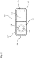
- the dental sensor 100 comprises a sensor housing 107 in which evaluation electronics 117 and a sensor unit are arranged.
- the evaluation electronics 117 and the sensor unit are suitable together for autonomously carrying out measurements of specific physical parameters on the tooth 105 .
- the sensor housing 107 is made of plastic, for example, in a standard form.
- the sensor housing 107 has a flat or approximately anatomically preformed contact surface 123 facing the tooth, which is covered with a flat layer of a malleable and plastic material 103 .
- the plastic material 103 forms a fastening area 101 for fastening the dental sensor 100 in the mouth area.
- a layer thickness of the plastic material 103 is 1 mm to 10 mm, for example.
- a suitable production-side structuring of the contact surface 123 of the sensor housing 107 or an anchoring of the plastic material 103 through holes in the sensor housing 107 can be provided.
- An anatomically shaped contact surface 123 of the sensor housing 107 or in the plastic material 103 has the advantage that the wearing comfort of the dental sensor 100 is improved and it interferes less with food intake.
- the natural shape of the dental arch can be used for additional adhesion of the dental sensor 100.
- the plastic and/or deformable material 103 deforms when it is pressed onto the tooth area 105, which can comprise one or more teeth. In this way, a three-dimensional impression of the tooth area 105 is obtained through the plastic material 103 .
- the plastic material 103 is then hardened so that it loses its deformability. This can be achieved, for example, by means of exposure to UV light, blue light, contact with oxygen or saliva, or by heat. It would also be conceivable to use a material that is first activated and then hardens in the tooth area 105 over time.
- the plastic material 103 is preferably prefabricated, so that the time required for attaching the dental sensor 100 is reduced and possible sources of error during processing are ruled out.
- the plastic material 103 comprises, for example, a hydrophilic vinylpolysiloxane impression material or a polymer based on methacrylates and various fillers linked to silanes, such as a light-curing nanohybrid composite.
- the plastic material 103 comprises, for example, a monomer matrix made up of dimethacrylates (17-18% by weight).
- Fillers include, for example, barium glass, ytterbium trifluoride and/or various oxides and copolymers (82-83% by weight).
- Additives, initiators, stabilizers and pigments can be additional ingredients ( ⁇ 1.0% by weight).
- the total amount of inorganic fillers is, for example, between 53 and 80% by volume.
- the particle sizes of the inorganic fillers are, for example, between 40 nm and 3 ⁇ m.
- the plastic material 103 can have antibiotic properties, such as by incorporating silver particles, copper particles or a mixture with chlorhexidine and chloroxylenol.
- the plastic material may include antibiotics such as penicillin, clindamycin, erythromycin, cefadroxil, metronidazole and/or tetracyclines.
- the plastic material 103 can also be formed by a silicone or a plasticine.
- the dental sensor 100 can, for example, comprise an electronic exposure device 109 which is arranged inside the sensor housing 107 .
- the exposure device 109 emits light by means of a light-emitting diode, which leads to the curing of the light-curing plastic material 103 .
- the sensor case 107 is formed of, for example, an optically transparent material that is in contact with the plastic material 103 .
- a chemical exposure device 109 can also be provided, which is based on the principle of chemiluminescence, is activated once and emits chemically generated light.
- the chemical exposure device 109 can be formed, for example, by a glow stick that can be inserted into the sensor housing 107 .
- the dental sensor 100 can also have a heating device 111 which is arranged inside the sensor housing 107 .
- the heater 111 emits heat by means of a heating coil, for example, which causes the thermosetting plastic material 103 to harden.
- a heating coil for example, which causes the thermosetting plastic material 103 to harden.
- between the heater 111 there is a metal as a heat conductive material between the heater 111 and the plastic material 103.
- a chemical heater 111 may be provided which is activated once and emits chemically generated heat.
- the exposure device 109 or the heating device 111 can be activated manually by actuating a switch or push button on the sensor housing so that they light up or heat for a predetermined period of time. At the end of this period, the plastic material 103 has hardened.
- the exposure device 109 or the heating device 111 can also be activated wirelessly via radio, for example via WLAN, NFC or Bluetooth using a mobile phone or tablet PC.
- a corresponding interface is implemented in the evaluation electronics 117, via which the exposure device 109 or the heating device 111 can be controlled.
- a separating layer 121 can be provided as a separating agent, which facilitates detachment of the dental sensor 100 from the tooth or the tooth area 105 after curing.
- the separating layer 121 is additionally arranged on the plastic material 103 and prevents direct contact between the tooth 105 and the plastic material 103.
- This separating layer 121 can be formed, for example, by a thin film of grease or oil or by a protective membrane made of rubber, Teflon or latex. In this case, the dental sensor 100 can be removed again without leaving any residue even without the hardened plastic material 103 .
- FIG. 2 shows a schematic top view of the dental sensor 100 and the plastic material 103.
- a cut-out or passage opening 115 in a predetermined shape can be provided on the production side, eg for a built-in sensor unit or any saliva ducts for better supply of saliva from the tooth area 105 to the sensor unit inside the sensor housing 107 during intraoral use.
- the sensor unit can be, for example, a sensor for measuring a pH value, an ethanol concentration, a lactate concentration, a cortisol concentration, a glucose concentration, an ion concentration, for measuring sound waves when biting and/or a sensor for measuring a temperature.
- the sensor unit within the dental sensor 100 can perform an intraoral measurement of different parameters over a longer period of time
- This recess or through-opening 115 provided can be made of plastic material 103, for example, which cannot be hardened in a surrounding region 119 around the through-opening 115. In the case of a light-curing material 103, this can be done, for example, by not introducing any photoinitiators into this surrounding area 119. This surrounding area 119 thus does not harden under the influence of light after the molding and can be removed relatively easily.
- the surrounding region 119 may also include a water soluble material such as sugar, cornstarch, or a water soluble filament.
- An anatomical adaptation of the dental sensor 100 can be achieved, for example, by tooth-shaped or concave bulges 113 in the contact surface 123 of the dental sensor 100, which correspond at least approximately to the tooth area 105. In this way, the dental sensor 100 can be closer are arranged on the tooth area 105. Not only the contact surface 123, but also the plastic material 103 can be anatomically preformed with corresponding tooth-shaped or concave bulges 113.
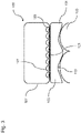
- 3 12 shows a further schematic view through the dental sensor 100.
- the attachment area 101 is attached to the plastic material 103 through a plurality of openings 129 which are arranged in the sensor housing 107.
- An internal curing step can then take place in order to strengthen the plate structures 127 . In this way, the plastic material 103 claws at the sensor housing 107 and can no longer be detached.
- the plastic material 101 supports itself through the mushroom-shaped structures 127 after hardening.
- Another way of attachment can be achieved by microstructuring the contact surface 123, for example by simply grinding it.
- the through-opening 115 can be provided in the plastic material 103 to enable a measurement by the sensor unit.
- the passage opening 115 forms an additional measuring area for the sensor unit next to the channels.
- the through-opening 115 can be made, for example, from plastic material 103 that cannot be hardened in a surrounding area 119 around the through-opening 115 .
- the channels 125 are formed by indentations in the plastic material 103 and are used to conduct or pass through liquid (saliva) to a sensor unit or to allow an exchange of air and ventilation of the measuring area.
- the channels 125 can be arranged in a horizontal, diagonal or vertical direction.
- the channels 125 can be formed, for example, by not introducing a photoinitiator into the light-curing plastic material 103 at the intended locations of the channels 125 . After light-curing, the non-curable plastic material 103 in these locations can be removed, such as with a water jet or spatula, without the photoinitiators, so as to leave the channels 125 in the attachment area 101 .
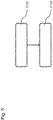
- figure 5 10 shows a block diagram of a method for inserting a dental sensor 100.
- step S101 when inserting the dental sensor 100, the tooth area 105 is molded using a plastic material 103 by pressing it onto the tooth area.
- the plastic material 103 adapts to the shape of the tooth 105 .
- step S102 the plastic material 103 is cured after molding.
- the dental sensor 100 can remain in the oral cavity or be hardened outside of the oral cavity. In this way, the attachment area 101 can be attached to a tooth 105 .
- the individual shaping can be accomplished in a few time-saving work steps directly in the patient's mouth in just one session.
- Such an anatomically individual shaping of an intraoral sensor carrier on the patient makes the dental sensor 100 suitable for permanent wear. This can during food intake, worn during conversations and while sleeping.
- the dental sensor 100 can be shaped and adapted directly by the dentist in a short time.
- a sensor positioning close to the tooth is made possible since the dental sensor 100 is anatomically individually adapted to the patient.
- All method steps can be implemented by means that are suitable for carrying out the respective method step. All functions performed by physical features can be a method step of a method.
Landscapes
- Health & Medical Sciences (AREA)
- Life Sciences & Earth Sciences (AREA)
- Engineering & Computer Science (AREA)
- Veterinary Medicine (AREA)
- Public Health (AREA)
- Physics & Mathematics (AREA)
- Biophysics (AREA)
- General Health & Medical Sciences (AREA)
- Biomedical Technology (AREA)
- Animal Behavior & Ethology (AREA)
- Medical Informatics (AREA)
- Surgery (AREA)
- Molecular Biology (AREA)
- Heart & Thoracic Surgery (AREA)
- Pathology (AREA)
- Oral & Maxillofacial Surgery (AREA)
- Dentistry (AREA)
- Orthopedic Medicine & Surgery (AREA)
- Physical Education & Sports Medicine (AREA)
- Rheumatology (AREA)
- Optics & Photonics (AREA)
- Epidemiology (AREA)
- High Energy & Nuclear Physics (AREA)
- Nuclear Medicine, Radiotherapy & Molecular Imaging (AREA)
- Radiology & Medical Imaging (AREA)
- Dental Tools And Instruments Or Auxiliary Dental Instruments (AREA)
Abstract
Description
- Die vorliegende Erfindung betrifft einen Dentalsensor für einen Intraoralbereich und ein Verfahren zum Einsetzen eines Dentalsensors.
- Nicht anatomisch korrekte Sensorgehäuse für die Anwendung im Intraoralbereich bieten einen schlechten Tragekomfort, stören unnötig stark bei der Nahrungsaufnahme und sind nicht ausreichend befestigt, da die natürliche Form des Zahnbogens nicht zur zusätzlichen Haftung verwendet werden kann. Zudem besteht die Gefahr, dass sich der Dentalsensor beim Tragen ablöst und verschluckt wird.
- Es ist die technische Aufgabe der vorliegenden Erfindung, einen Dentalsensor bereitzustellen, das auf einfache und schnelle Weise von einem Anwender im Intraoralraum befestigt werden kann.
- Diese Aufgabe wird durch Gegenstände nach den unabhängigen Ansprüchen gelöst. Technisch vorteilhafte Ausführungsformen sind Gegenstand der abhängigen Ansprüche, der Beschreibung und der Zeichnungen.
- Gemäß einem ersten Aspekt wird die technische Aufgabe durch einen Dentalsensor für einen Intraoralbereich gelöst, mit einem Befestigungsbereich aus plastischem Material zum Abformen eines Mundbereichs beim Einsetzen des Dentalsensors, das nach dem Abformen aushärtbar ist. Das Aushärten kann innerhalb oder außerhalb der Mundhöhle erfolgen, d.h. intraoral oder extraoral. Der Mundbereich kann einen Zahnbereich mit einem oder mehreren Zähnen umfassen, der optional mit dem Zahnfleisch in Kontakt stehen kann.
- Durch die Formgebung des plastischen Materials kann der Dentalsensor schnell und individuell an die räumlichen Gegebenheiten im Intraoralraum angepasst werden. Im Ergebnis kann die Position des Dentalsensors besser festgelegt werden. Die Formgebung kann beispielsweise in wenigen Minuten direkt von einem Zahnarzt vorgenommen werden. Bei einer Befestigung mittels einer anatomisch korrekten Formgebung muss nicht auf eine aufwändig zu entfernende und zahnschädigende Befestigung mittels einer chemischen Adhäsion zurückgegriffen werden.
- In einer technisch vorteilhaften Ausführungsform des Dentalsensors ist das plastische Material mittels Lichts, elektromagnetischer Strahlung oder Wärme aushärtbar. Das plastische Material kann auch durch Trocknen, durch eine chemische Reaktion mit Wasser (Hydratation) oder additionsvernetzend aushärtbar sein. Dadurch wird beispielsweise der technische Vorteil erreicht, dass das Aushärten gezielt nach dem Abformen initiiert werden kann.
- In einer weiteren technisch vorteilhaften Ausführungsform des Dentalsensors umfasst das plastische Material ein aushärtbares Polymer. Dadurch wird beispielsweise der technische Vorteil erreicht, dass besonders geeignete Materialien verwendet werden, die schnell aushärten. Das plastische Material kann nach dem Aushärten eine Restflexibilität oder Restelastizität behalten, so dass sich dieses leichter entfernen lässt, wie beispielsweise silikonartige Materialen. Dadurch wird beispielsweise der technische Vorteil erreicht, dass der Dentalsensor auch dann entfernt werden kann, wenn sich dieser verkeilt, beispielsweise wenn der Dentalsensor an einer Zahnlücke befestigt wird.
- In einer weiteren technisch vorteilhaften Ausführungsform des Dentalsensors ist das plastische Material an einem Sensorgehäuse des Dentalsensors angeordnet. Dadurch wird beispielsweise der technische Vorteil erreicht, dass das Sensorgehäuse an dem Zahnbereich befestigt werden kann.
- In einer weiteren technisch vorteilhaften Ausführungsform des Dentalsensors wird eine Verbindung zwischen dem Befestigungsbereich und dem Dentalsensor oder dem Sensorgehäuse mittels einem positiv ausgestalteten Verbindungsmittel hergestellt wird. Das positiv ausgestalteten Verbindungsmittel umfasst beispielsweise ein oder mehrere herausstehende Noppen oder Anker, die sich mit dem plastischen Material verbinden. Dabei verformt, formt oder drückt sich das plastische Material um diese Struktur. Dadurch wird beispielsweise der technische Vorteil erreicht, dass eine zuverlässige Verbindung zwischen dem Befestigungsbereich und dem Dentalsensor erzielt werden kann.
- In einer weiteren technisch vorteilhaften Ausführungsform des Dentalsensors umfasst das Sensorgehäuse ein transparentes oder wärmeleitendes Material und das transparente oder wärmeleitende Material steht in Kontakt mit dem plastischen Material. Dadurch wird beispielsweise der technische Vorteil erreicht, dass das Licht oder die Wärme an das plastische Material herangeführt werden kann und das plastische Material effizient ausgehärtet werden kann.
- In einer weiteren technisch vorteilhaften Ausführungsform des Dentalsensors umfasst der Dentalsensor eine Belichtungseinrichtung oder eine Heizeinrichtung für das plastische Material. Dadurch wird beispielsweise der technische Vorteil erreicht, dass das plastische Material direkt von dem Dentalsensor ausgehärtet werden kann.
- In einer weiteren technisch vorteilhaften Ausführungsform des Dentalsensors ist die Belichtungseinrichtung oder die Heizeinrichtung durch einen Benutzer aktivierbar. Dadurch wird beispielsweise der technische Vorteil erreicht, dass der Benutzer die Aushärtung des plastischen Materials steuern kann.
- In einer weiteren technisch vorteilhaften Ausführungsform des Dentalsensors erfolgt die Aktivierung der Belichtungseinrichtung oder der Heizeinrichtung drahtlos. Die Aktivierung der Belichtungseinrichtung oder der Heizeinrichtung kann beispielsweise über W-Lan, NFC oder Bluetooth mittels eines Mobiltelefons durchgeführt werden. Dadurch wird beispielsweise der technische Vorteil erreicht, dass keine Betätigungshandlungen im Intraoralraum erforderlich sind.
- In einer weiteren technisch vorteilhaften Ausführungsform des Dentalsensors umfasst der Befestigungsbereich, der Dentalsensor und/oder das Sensorgehäuse eine vorgefertigte Durchgangsöffnung und/oder ein oder mehrere Kanäle. Dadurch wird beispielsweise der technische Vorteil erreicht, dass Flüssigkeit von dem Zahn direkt an einen Sensor geführt werden kann, der die Flüssigkeit analysiert.
- In einer weiteren technisch vorteilhaften Ausführungsform des Dentalsensors ist der Bereich um die Durchgangsöffnung nicht aushärtbar. Dadurch wird beispielsweise der technische Vorteil erreicht, dass der Dentalsensor nach dem Aushärten leicht entfernt werden kann.
- In einer weiteren technisch vorteilhaften Ausführungsform des Dentalsensors ist das plastische Material anatomisch vorgeformt. Die anatomische Vorformung kann beispielsweise entsprechende zahnförmige Ausbuchtungen für einzelne Zähne umfassen. Dadurch wird beispielsweise der technische Vorteil erreicht, dass sich der Dentalsensor besser an den Zahnbereich anformt.
- In einer weiteren technisch vorteilhaften Ausführungsform des Dentalsensors ist auf dem plastischen Material eine Trennschicht zum Ablösen des plastischen Materials vom Zahnbereich angeordnet. Dadurch wird beispielsweise der technische Vorteil erreicht, dass der Dentalsensor nach der Abformung leicht entfernt werden kann.
- Gemäß einem zweiten Aspekt wird die technische Aufgabe durch ein Verfahren zum Einsetzen eines Dentalsensors für einen Intraoralbereich gelöst, mit den Schritten eines Abformens eines Zahnbereichs beim Einsetzen des Dentalsensors mittels eines plastischen Materials; und eines Aushärtens des plastischen Materials nach dem Abformen. Dadurch werden die gleichen technischen Vorteile wie durch das Verfahren nach dem ersten Aspekt erreicht.
- In einer technisch vorteilhaften Ausführungsform des Verfahrens erfolgt das Aushärten mittels Lichts, elektromagnetischer Strahlung oder Wärme. Dadurch wird beispielsweise ebenfalls der technische Vorteil erreicht, dass das Aushärten gezielt nach dem Abformen initiiert werden kann.
- Ausführungsbeispiele der Erfindung sind in den Zeichnungen dargestellt und werden im Folgenden näher beschrieben.
- Es zeigen:
- Fig. 1
- eine schematische Seitenansicht eines Dentalsensors;
- Fig. 2
- eine schematische Aufsicht auf das Dentalsensor;
- Fig. 3
- eine schematische Ansicht durch den Dentalsensor;
- Fig. 4
- eine schematische Ansicht durch den Dentalsensor und/oder Befestigungsbereich mit unterschiedlichen Kanälen; und
- Fig. 5
- ein Blockdiagramm eines Verfahrens zum Einsetzen eines Dentalsensors.
-
Fig. 1 zeigt eine schematische Seitenansicht eines Dentalsensors 100. Der Dentalsensor 100 umfasst ein Sensorgehäuse 107, in dem eine Auswerteelektronik 117 und eine Sensoreinheit angeordnet sind. Die Auswerteelektronik 117 und die Sensoreinheit sind zusammen geeignet, am Zahn 105 autonom Messungen von bestimmten physikalischen Parametern durchzuführen. Das Sensorgehäuse 107 ist beispielsweise in einer Standardform aus Kunststoff gefertigt. - Das Sensorgehäuse 107 weist eine ebene oder annähernd anatomisch vorgeformte zahnzugewandte Kontaktfläche 123 auf, die mit einer flächigen Schicht aus einem formbaren und plastischen Material 103 bedeckt ist. Das plastische Material 103 bildet einen Befestigungsbereich 101 zur Befestigung des Dentalsensors 100 im Mundbereich. Eine Schichtdicke des plastischen Materials 103 beträgt beispielsweise 1 mm bis 10 mm. Zur Befestigung des plastischen Materials 103 kann eine geeignete produktionsseitige Strukturierung der Kontaktfläche 123 des Sensorgehäuses 107 oder eine Verankerung des plastischen Materials 103 durch Löcher im Sensorgehäuse 107 vorgesehen sein.
- Eine anatomisch geformte Kontaktfläche 123 des Sensorgehäuses 107 oder im plastischen Material 103 weist den Vorteil auf, dass sich der Tragekomfort des Dentalsensors 100 verbessert und dieser weniger bei der Nahrungsaufnahme stört. Die natürliche Form des Zahnbogens kann zur zusätzlichen Haftung des Dentalsensors 100 verwendet werden.
- Das plastische und/oder verformbare Material 103 verformt sich bei einem Aufdrücken auf den Zahnbereich 105, der ein oder mehrere Zähne umfassen kann. Auf diese Weise wird durch das plastische Material 103 ein räumlicher Abdruck des Zahnbereichs 105 gewonnen. Anschließend wird das plastische Material 103 ausgehärtet, so dass dieses seine Verformbarkeit verliert. Dies kann beispielsweise mittels einer Bestrahlung mit UV-Licht, blauem Licht, im Kontakt mit Sauerstoff oder Speichel oder durch Wärme erreicht werden. Denkbar wäre ebenso die Verwendung eines Materials, das zunächst aktiviert wird und dann mit der Zeit am Zahnbereich 105 aushärtet. Vorzugsweise ist das plastische Material 103 vorgefertigt, so dass der Zeitbedarf bei der Befestigung des Dentalsensors 100 verringert wird und möglichen Fehlerquellen bei der Verarbeitung ausgeschlossen werden.
- Das plastische Material 103 umfasst beispielsweise eine hydrophile Vinylpolysiloxan-Abformmasse oder ein Polymer auf Basis von Methacrylaten und verschiedenen Füllstoffen, die mit Silanen verbunden sind, wie beispielsweise ein lichthärtendes Nanohybrid-Composite.
- Das plastische Material 103 umfasst beispielsweise eine Monomer-Matrix, die aus Dimethacrylates (17-18 Gew%) aufgebaut ist. Füllstoffe umfassen beispielsweise Bariumglas, Ytterbium-Trifluorid und/oder unterschiedliche Oxide und Copolymere (82-83 Gew%). Additive, Initiatoren, Stabilisatoren und Pigmente können zusätzliche Inhaltsstoffe sein (<1.0 Gew%). Die Gesamtmenge der anorganischen Füllstoffe beträgt beispielsweise zwischen 53 und 80 Vol%. Die Partikelgrößen der anorganischen Füllstoffe liegen beispielsweise zwischen 40 nm and 3 µm.
- Das plastische Material 103 kann antibiotische Eigenschaften aufweisen, wie beispielsweise durch einen Einbau von Silberpartikeln, Kupferpartikeln oder eine Mischung mit Chlorhexidin and Chloroxylenol. Zudem kann das plastische Material Antibiotika umfassen, wie beispielsweise Penicillin, Clindamycin, Erythromycin, Cefadroxil, Metronidazol und/oder Tetracycline. Das plastische Material 103 kann auch durch ein Silikon oder ein Plastilin gebildet sein.
- Der Dentalsensor 100 kann beispielsweise eine elektronische Belichtungseinrichtung 109 umfassen, die im Inneren des Sensorgehäuses 107 angeordnet ist. Die Belichtungseinrichtung 109 sendet Licht mittels einer Leuchtdiode aus, das zum Aushärten des lichthärtenden plastischen Materials 103 führt. In diesem Fall ist das Sensorgehäuse 107 beispielsweise aus einem optisch transparenten Material gebildet, das in Kontakt mit dem plastischen Material 103 steht. Dadurch kann das Licht zum Aushärten aus einem Inneren des Dentalsensors 100 durch das Sensorgehäuse 107 auf das plastische Material 103 treffen und dieses aushärten. Allerdings kann auch eine chemische Belichtungseinrichtung 109 vorgesehen sein, die auf dem Prinzip der Chemolumineszenz beruht, einmal aktiviert wird und chemisch erzeugtes Licht aussendet. Die chemische Belichtungseinrichtung 109 kann beispielsweise durch einen Leuchtstab gebildet sein, der in das Sensorgehäuse 107 einsetzbar ist.
- Der Dentalsensor 100 kann aber auch eine Heizeinrichtung 111 aufweisen, die im Inneren des Sensorgehäuses 107 angeordnet ist. Die Heizeinrichtung 111 sendet beispielsweise Wärme mittels einer Heizspirale aus, die zum Aushärten des wärmehärtenden plastischen Materials 103 führt. In diesem Fall befindet sich zwischen der Heizeinrichtung 111 ein Metall als wärmeleitendes Material zwischen der Heizeinrichtung 111 und dem plastischen Material 103. Durch das wärmeleitende Material kann die erzeugte Wärme zum Aushärten wirksam an das plastische Material 103 geführt werden und dieses aushärten. Allerdings kann auch eine chemische Heizeinrichtung 111 vorgesehen sein, die einmal aktiviert wird und chemisch erzeugte Wärme aussendet.
- Die Belichtungseinrichtung 109 oder die Heizeinrichtung 111 können manuell durch Betätigen eines Schalters oder Druckknopfes am Sensorgehäuse aktiviert werden, so dass diese für einen vorgegebenen Zeitraum leuchten oder heizen. Am Ende dieses Zeitraumes ist das plastische Material 103 ausgehärtet.
- Die Belichtungseinrichtung 109 oder die Heizeinrichtung 111 können jedoch auch drahtlos über Funk aktiviert werden, beispielsweise über WLAN, NFC oder Bluetooth mittels eines Mobiltelefons oder Tablet-PCs. In diesem Fall ist in der Auswerteelektronik 117 eine entsprechende Schnittstelle implementiert, über die Belichtungseinrichtung 109 oder Heizeinrichtung 111 gesteuert werden kann.
- Zudem kann eine Trennschicht 121 als Trennmittel vorgesehen sein, durch die ein Ablösen des Dentalsensors 100 von dem Zahn oder dem Zahnbereich 105 nach dem Aushärten erleichtert wird. Die Trennschicht 121 ist zusätzlich auf dem plastischen Material 103 angeordnet und verhindert einen direkten Kontakt zwischen dem Zahn 105 und dem plastischen Material 103. Diese Trennschicht 121 kann beispielsweise einen dünnen Fett- oder Ölfilm oder durch eine Schutzmembran aus Gummi, Teflon oder Latex gebildet sein. In diesem Fall kann der Dentalsensor 100 auch ohne ausgehärtetes plastisches Material 103 wieder rückstandsfrei entfernt werden.
-
Fig. 2 zeigt eine schematische Aufsicht auf den Dentalsensor 100 und das plastische Material 103. Auf der dem Zahn 105 zugewandten Seite des plastischen Materials 103 kann bereits produktionsseitig eine Aussparung oder Durchgangsöffnung 115 in einer vorgegebenen Form vorgesehen sein, z.B. für eine verbaute Sensoreinheit oder etwaige Speichelkanäle zur besseren Zuführung von Speichel vom Zahnbereich 105 zu der Sensoreinheit im Inneren des Sensorgehäuses 107 während der intraoralen Anwendung. - Die Sensoreinheit kann beispielsweise ein Sensor zum Messen eines pH-Wertes, einer Ethanol-Konzentration, einer Lactat-Konzentration, einer Cortisol-Konzentration, einer GlucoseKonzentration, einer Ionenkonzentration, zum Messen von Schallwellen beim Aufeinanderbeißen und oder ein Sensor zum Messen einer Temperatur sein. Im Allgemeinen kann durch die Sensoreinheit innerhalb des Dentalsensors 100 eine intraorale Messung unterschiedlicher Kenngrößen über einen längeren Zeitraum durchgeführt werden
- Diese vorgesehene Aussparung oder Durchgangsöffnung 115 kann beispielsweise aus plastischem Material 103 gefertigt sein, das in einem Umgebungsbereich 119 um die Durchgangsöffnung 115 herum nicht aushärtbar ist. Dies kann im Falle eines lichthärtenden Materials 103 beispielsweise dadurch geschehen, dass keine Photoinitiatoren in diesen Umgebungsbereich 119 eingebracht werden. Dieser Umgebungsbereich 119 härtet somit nach der Abformung unter Einfluss des Lichtes nicht aus und kann relativ leicht entfernt werden. Der Umgebungsbereich 119 kann auch ein wasserlösliches Material umfassen, wie beispielsweise Zucker, Maisstärke oder ein wasserlösliches Filament.
- Eine anatomische Anpassung des Dentalsensors 100 kann beispielsweise durch zahnförmige oder konkave Ausbuchtungen 113 in der Kontaktfläche 123 des Dentalsensors 100 erreicht werden, die die zumindest näherungsweise dem Zahnbereich 105 entsprechen. Auf diese Weise kann der Dentalsensor 100 näher am Zahnbereich 105 angeordnet werden. Nicht nur die Kontaktfläche 123, sondern auch das plastische Material 103 kann mit entsprechenden zahnförmigen oder konkaven Ausbuchtungen 113 anatomisch vorgeformt sein.
-
Fig. 3 zeigt eine weitere schematische Ansicht durch den Dentalsensor 100. Die Befestigung des Befestigungsbereichs 101 mit dem plastischen Material 103 erfolgt durch eine Mehrzahl von Öffnungen 129, die in dem Sensorgehäuse 107 angeordnet sind. Das plastische und ungehärtete Material 103 wird beim Befestigen durch die Öffnungen 129 in der Gehäusewand teilweise hindurchgedrückt und anschließend auf der Innenseite des Sensorgehäuse 107 plattgedrückt. Danach kann ein innenseitiger Aushärteschritt erfolgen, um die platten Strukturen 127 zu verfestigen. Auf diese Weise krallt sich das plastischen Material 103 am Sensorgehäuse 107 fest und kann sich nicht mehr lösen. Das plastische Material 101 hält sich selbst durch die pilzförmigen Strukturen 127 nach dem Aushärten. - Eine andere Möglichkeit der Befestigung kann durch eine Mikrostrukturierung der Kontaktfläche 123 erreicht werden, wie beispielsweise durch einfaches Anschleifen.
-
Fig. 4 zeigt eine schematische Ansicht des Befestigungsbereiches 101, des Dentalsensors 100 und/oder des Dentalsensorgehäuses 107 mit unterschiedlichen Kanälen 125. Des Weiteren kann in dem plastischen Material 103 die Durchgangsöffnung 115 zum Ermöglichen einer Messung durch Sensoreinheit vorgesehen sein. Die Durchgangsöffnung 115 bildet einen zusätzlichen Messbereich für die Sensoreinheit neben den Kanälen. Die Durchgangsöffnung 115 kann beispielsweise aus plastischem Material 103 gefertigt sein, das in einem Umgebungsbereich 119 um die Durchgangsöffnung 115 herum nicht aushärtbar ist. - Die Kanäle 125 sind in der dem plastischen Material 103 durch Vertiefungen gebildet und dienen dazu Flüssigkeit (Speichel) zu einer Sensoreinheit zu leiten oder durchzuführen oder einen Luftaustausch und eine Ventilation des Messbereichs zu ermöglichen. Die Kanäle 125 können in horizontaler, diagonaler oder vertikaler Richtung angeordnet sein.
- Die Kanäle 125 können beispielsweise dadurch gebildet werden, dass an den vorgesehenen Stellen der Kanäle 125 kein Photoinitiator in das lichthärtende plastischen Material 103 eingebracht wird. Nach einem Aushärten mittels Lichts kann an diesen Stellen das nicht-härtbare plastische Material 103 ohne die Photoinitiatoren entfernt werden, wie beispielsweise mit einem Wasserstrahl oder einem Spatel, um so die Kanäle 125 in dem Befestigungsbereich 101 zu erhalten.
-
Fig. 5 zeigt ein Blockdiagramm eines Verfahrens zum Einsetzen eines Dentalsensors 100. Im Schritt S101 wird der Zahnbereich 105 beim Einsetzen des Dentalsensors 100 mittels eines plastischen Materials 103 abgeformt, indem dieses auf den Zahnbereich gedrückt wird. Das plastische Material 103 passt sich dabei der Form des Zahns 105 an. Anschließend wird im Schritt S102 das plastische Material 103 nach dem Abformen ausgehärtet. Je nach Ausgestaltung kann der Dentalsensor 100 dabei in der Mundhöhle verbleiben oder außerhalb der Mundhöhle ausgehärtet werden. Auf diese Weise kann der Befestigungsbereich 101 an einem Zahn 105 befestigt werden. - Die individuelle Formgebung kann in wenigen zeitsparenden Arbeitsschritten direkt im Mund eines Patienten in nur einer Sitzung bewerkstelligt werden. Durch eine derartig anatomisch individuelle Formgebung eines intraoralen Sensorträgers auf den Patienten ist der Dentalsensor 100 geeignet, dauerhaft getragen zu werden. Dieser kann bei einer Nahrungsaufnahme, bei Gesprächen und im Schlaf getragen werden. Im Vergleich zum individuellen 3D-Druck mittels Abformung, Scan und Produktion im Zahnlabor kann die Formgebung und Anpassung des Dentalsensors 100 in kurzer Zeit direkt vom Zahnarzt vorgenommen werden. Daneben wird eine Sensorpositionierung nahe am Zahn ermöglicht, da der Dentalsensor 100 anatomisch individuell auf den Patienten angepasst ist.
- Alle in Verbindung mit einzelnen Ausführungsformen der Erfindung erläuterten und gezeigten Merkmale können in unterschiedlicher Kombination in dem erfindungsgemäßen Gegenstand vorgesehen sein, um gleichzeitig deren vorteilhafte Wirkungen zu realisieren.
- Alle Verfahrensschritte können durch Einrichtungen implementiert werden, die zum Ausführen des jeweiligen Verfahrensschrittes geeignet sind. Alle Funktionen, die von gegenständlichen Merkmalen ausgeführt werden, können ein Verfahrensschritt eines Verfahrens sein.
- Der Schutzbereich der vorliegenden Erfindung ist durch die Ansprüche gegeben und wird durch die in der Beschreibung erläuterten oder den Figuren gezeigten Merkmale nicht beschränkt.
-
- 100
- Dentalsensor
- 101
- Befestigungsbereich
- 103
- plastisches Material
- 105
- Zahnbereich/Zahn
- 107
- Sensorgehäuse
- 109
- Belichtungseinrichtung
- 111
- Heizeinrichtung
- 113
- Ausbuchtung
- 115
- Durchgangsöffnung
- 117
- Auswertelektronik
- 119
- Umgebungsbereich
- 121
- Trennschicht
- 123
- Kontaktfläche
- 125
- Kanal
- 127
- Struktur
- 129
- Öffnung
Claims (15)
- Dentalsensor (100) für einen Intraoralbereich, mit:
einem Befestigungsbereich (101) aus plastischem Material (103) zum Abformen eines Mundbereichs (105) beim Einsetzen des Dentalsensors (100), das nach dem Abformen aushärtbar ist. - Dentalsensor (100) nach Anspruch 1, wobei das plastische Material (103) mittels Lichts, elektromagnetischer Strahlung oder Wärme aushärtbar ist
- Dentalsensor (100) nach einem der vorangehenden Ansprüche, wobei das plastische Material (103) ein aushärtbares Polymer umfasst.
- Dentalsensor (100) nach einem der vorangehenden Ansprüche, wobei das plastische Material (103) an einem Sensorgehäuse (107) des Dentalsensors (100) angeordnet ist.
- Dentalsensor (100) nach einem der vorangehenden Ansprüche, wobei eine Verbindung zwischen dem Befestigungsbereich (101) und dem Dentalsensor (100) oder dem Sensorgehäuse (107) mittels einem positiv ausgestalteten Verbindungsmittel hergestellt wird.
- Dentalsensor (100) nach Anspruch 4, wobei das Sensorgehäuse (107) ein transparentes oder wärmeleitendes Material umfasst und das transparente oder wärmeleitende Material in Kontakt mit dem plastischen Material steht.
- Dentalsensor (100) nach einem der vorangehenden Ansprüche, wobei der Dentalsensor (100) eine Belichtungseinrichtung (109) oder eine Heizeinrichtung (111) für das plastische Material umfasst.
- Dentalsensor (100) nach Anspruch 7, wobei die Belichtungseinrichtung (109) oder die Heizeinrichtung (111) durch einen Benutzer aktivierbar ist.
- Dentalsensor (100) nach Anspruch 8, wobei die Aktivierung der Belichtungseinrichtung (109) oder der Heizeinrichtung (111) drahtlos erfolgt.
- Dentalsensor (100) nach einem der vorangehenden Ansprüche, wobei der Befestigungsbereich (101), der Dentalsensor (100) und/oder das Sensorgehäuse (107) eine vorgefertigte Durchgangsöffnung (115) und/oder ein oder mehrere Kanäle (125) umfasst.
- Dentalsensor (100) nach einem der vorangehenden Ansprüche, wobei der Umgebungsbereich (119) des plastischen Materials (103) um die Durchgangsöffnung (115) nicht aushärtbar ist.
- Dentalsensor (100) nach einem der vorangehenden Ansprüche, wobei das plastische Material (103) anatomisch vorgeformt ist.
- Dentalsensor (100) nach einem der vorangehenden Ansprüche, wobei auf dem plastischen Material (103) eine Trennschicht (121) zum Ablösen des plastischen Materials (103) vom Mundbereich (103) angeordnet ist.
- Verfahren zum Einsetzen eines Dentalsensors (100) für einen Intraoralbereich, mit den Schritten:- Abformen (S101) eines Mundbereichs (105) beim Einsetzen des Dentalsensors (100) mittels eines plastischen Materials (103); und- Aushärten (S102) des plastischen Materials (103) nach dem Abformen.
- Verfahren nach Anspruch 14, wobei das Aushärten mittels Lichts, elektromagnetischer Strahlung oder Wärme erfolgt.
Priority Applications (7)
| Application Number | Priority Date | Filing Date | Title |
|---|---|---|---|
| EP24157317.9A EP4342421A3 (de) | 2020-12-16 | 2020-12-16 | Dentalsensor für den intraoralbereich |
| EP20214651.0A EP4014880B1 (de) | 2020-12-16 | 2020-12-16 | Dentalsensor für den intraoralbereich |
| KR1020237020065A KR20230118856A (ko) | 2020-12-16 | 2021-11-30 | 구강내 영역을 위한 치과용 센서 |
| JP2023535790A JP7724288B2 (ja) | 2020-12-16 | 2021-11-30 | 口腔内領域用の歯科用センサ |
| PCT/EP2021/083511 WO2022128439A1 (de) | 2020-12-16 | 2021-11-30 | Dentalsensor für den intraoralbereich |
| CN202180051750.XA CN115884731A (zh) | 2020-12-16 | 2021-11-30 | 用于口内区域的牙科传感器 |
| US17/541,655 US20220183624A1 (en) | 2020-12-16 | 2021-12-03 | Dental Sensor For The Intraoral Region |
Applications Claiming Priority (1)
| Application Number | Priority Date | Filing Date | Title |
|---|---|---|---|
| EP20214651.0A EP4014880B1 (de) | 2020-12-16 | 2020-12-16 | Dentalsensor für den intraoralbereich |
Related Child Applications (1)
| Application Number | Title | Priority Date | Filing Date |
|---|---|---|---|
| EP24157317.9A Division EP4342421A3 (de) | 2020-12-16 | 2020-12-16 | Dentalsensor für den intraoralbereich |
Publications (3)
| Publication Number | Publication Date |
|---|---|
| EP4014880A1 true EP4014880A1 (de) | 2022-06-22 |
| EP4014880B1 EP4014880B1 (de) | 2024-03-06 |
| EP4014880C0 EP4014880C0 (de) | 2024-03-06 |
Family
ID=73855123
Family Applications (2)
| Application Number | Title | Priority Date | Filing Date |
|---|---|---|---|
| EP20214651.0A Active EP4014880B1 (de) | 2020-12-16 | 2020-12-16 | Dentalsensor für den intraoralbereich |
| EP24157317.9A Withdrawn EP4342421A3 (de) | 2020-12-16 | 2020-12-16 | Dentalsensor für den intraoralbereich |
Family Applications After (1)
| Application Number | Title | Priority Date | Filing Date |
|---|---|---|---|
| EP24157317.9A Withdrawn EP4342421A3 (de) | 2020-12-16 | 2020-12-16 | Dentalsensor für den intraoralbereich |
Country Status (6)
| Country | Link |
|---|---|
| US (1) | US20220183624A1 (de) |
| EP (2) | EP4014880B1 (de) |
| JP (1) | JP7724288B2 (de) |
| KR (1) | KR20230118856A (de) |
| CN (1) | CN115884731A (de) |
| WO (1) | WO2022128439A1 (de) |
Families Citing this family (3)
| Publication number | Priority date | Publication date | Assignee | Title |
|---|---|---|---|---|
| EP4285863B1 (de) * | 2020-12-16 | 2025-07-02 | Ivoclar Vivadent AG | Dentales befestigungssystem und nichttherapeutisches verfahren zum befestigen eines dentalobjekts |
| EP4226894A1 (de) * | 2020-12-16 | 2023-08-16 | Ivoclar Vivadent AG | Dentalobjekt mit einem haftbereich |
| EP4295767B1 (de) * | 2022-06-21 | 2025-09-10 | Ivoclar Vivadent AG | Schaltungsgehäuse für eine tragbare intraorale anwendung |
Citations (2)
| Publication number | Priority date | Publication date | Assignee | Title |
|---|---|---|---|---|
| US5090047A (en) * | 1990-10-23 | 1992-02-18 | Applied Research Company | Apparatus for reproducibly positioning an image receptor for intraoral diagnostics |
| WO2016105592A1 (en) * | 2014-12-24 | 2016-06-30 | Chodorow Ingram | Disposable surgical intervention guides, methods, and kits |
Family Cites Families (27)
| Publication number | Priority date | Publication date | Assignee | Title |
|---|---|---|---|---|
| JPS5058895A (de) * | 1973-09-24 | 1975-05-21 | ||
| JP2000083952A (ja) * | 1998-09-11 | 2000-03-28 | Nikkusu:Kk | 歯科用フイルム/センサ収納具 |
| US7610919B2 (en) * | 2004-05-28 | 2009-11-03 | Aetherworks Ii, Inc. | Intraoral aversion devices and methods |
| US8899976B2 (en) * | 2004-09-24 | 2014-12-02 | Align Technology, Inc. | Release agent receptacle |
| US8023676B2 (en) * | 2008-03-03 | 2011-09-20 | Sonitus Medical, Inc. | Systems and methods to provide communication and monitoring of user status |
| JP2010131181A (ja) | 2008-12-04 | 2010-06-17 | Tokuyama Dental Corp | マウスガードの製造方法 |
| GB201317478D0 (en) * | 2013-10-02 | 2013-11-13 | Provost Fellows Foundation Scholars And The Other Members Of Board Of The | A sensor for an oral appliance |
| MX2017008279A (es) * | 2014-12-23 | 2018-02-01 | Behr Process Corp | Metodos y aparatos para la venta de productos de pintura en tiendas que tradicionalmente no venden pintura. |
| DE102015102058A1 (de) * | 2015-02-12 | 2016-08-18 | Matthias Hodecker | Zahnmedizinische Vorrichtung mit Übertragungsschale |
| US20230181350A1 (en) * | 2015-03-04 | 2023-06-15 | Real 3D Polymers, LLC | Dual purpose orthodontic appliance for alignment, bruxism, and sleep apnea with smart sensors and control module system |
| JP6923943B2 (ja) * | 2015-12-15 | 2021-08-25 | エミュデント テクノロジーズ プロプライエタリー リミテッドEmuDent Technologies Pty Ltd | 歯科装置 |
| CN108366848A (zh) * | 2015-12-17 | 2018-08-03 | 3M创新有限公司 | 单件式牙科修复模具 |
| US10314537B2 (en) * | 2016-06-07 | 2019-06-11 | Peter John Zegarelli | Oral data collecting device for diagnosis or prognosis |
| EP3254641B1 (de) * | 2016-06-08 | 2020-12-09 | Ivoclar Vivadent AG | Verfahren zur herstellung eines aufsatzes oder ansatzes eines strahlungshärtgeräts, aufsatz oder ansatz und dentalrestaurationserzeugungsvorrichtung |
| US20180085059A1 (en) * | 2016-09-29 | 2018-03-29 | Jin Kyun LEE | Wearable apparatus attaching on tooth and the sensing device fixing at tooth |
| US20180177570A1 (en) | 2016-12-28 | 2018-06-28 | Ormco Corporation | Light assisted orthodontic devices and methods of making and using same |
| JP2020513943A (ja) * | 2017-01-25 | 2020-05-21 | デンツプライ シロナ インコーポレイテッド | 光硬化デンタルシステム |
| KR20180115371A (ko) * | 2017-04-12 | 2018-10-23 | 주식회사 비엘시스템 | 마우스피스 타입의 광 치료기 |
| US11504060B2 (en) * | 2017-06-23 | 2022-11-22 | Martha Ann Keels | Dental retainer with pH sensor |
| US10639134B2 (en) * | 2017-06-26 | 2020-05-05 | Align Technology, Inc. | Biosensor performance indicator for intraoral appliances |
| US12171575B2 (en) * | 2017-10-04 | 2024-12-24 | Align Technology, Inc. | Intraoral systems and methods for sampling soft-tissue |
| US20190175104A1 (en) * | 2017-12-10 | 2019-06-13 | Bela Malik | In-situ salivary component collection, concentration, isolation, analytics, and communication system |
| CN210784761U (zh) * | 2019-08-13 | 2020-06-19 | 上海正雅齿科科技股份有限公司 | 一种自助式附件模板 |
| EP3878400B1 (de) * | 2020-03-13 | 2023-10-18 | Seiko Group Corporation | Intraorale sensorvorrichtung und verfahren zu ihrer herstellung |
| US12390359B2 (en) * | 2021-01-19 | 2025-08-19 | 3 Little Ladies, Inc. | Therapeutic oral device |
| US20230030704A1 (en) * | 2021-07-29 | 2023-02-02 | UCHU Biosensors, Inc. | Systems for measuring patient physiologic parameters |
| US20240032824A1 (en) * | 2022-07-27 | 2024-02-01 | Dianyx Innovations, LLC | Systems and Methods for Intraoral pH Monitoring |
-
2020
- 2020-12-16 EP EP20214651.0A patent/EP4014880B1/de active Active
- 2020-12-16 EP EP24157317.9A patent/EP4342421A3/de not_active Withdrawn
-
2021
- 2021-11-30 CN CN202180051750.XA patent/CN115884731A/zh active Pending
- 2021-11-30 WO PCT/EP2021/083511 patent/WO2022128439A1/de not_active Ceased
- 2021-11-30 JP JP2023535790A patent/JP7724288B2/ja active Active
- 2021-11-30 KR KR1020237020065A patent/KR20230118856A/ko active Pending
- 2021-12-03 US US17/541,655 patent/US20220183624A1/en active Pending
Patent Citations (2)
| Publication number | Priority date | Publication date | Assignee | Title |
|---|---|---|---|---|
| US5090047A (en) * | 1990-10-23 | 1992-02-18 | Applied Research Company | Apparatus for reproducibly positioning an image receptor for intraoral diagnostics |
| WO2016105592A1 (en) * | 2014-12-24 | 2016-06-30 | Chodorow Ingram | Disposable surgical intervention guides, methods, and kits |
Also Published As
| Publication number | Publication date |
|---|---|
| JP7724288B2 (ja) | 2025-08-15 |
| WO2022128439A1 (de) | 2022-06-23 |
| CN115884731A (zh) | 2023-03-31 |
| EP4014880B1 (de) | 2024-03-06 |
| EP4014880C0 (de) | 2024-03-06 |
| US20220183624A1 (en) | 2022-06-16 |
| JP2023553464A (ja) | 2023-12-21 |
| EP4342421A3 (de) | 2024-06-19 |
| EP4342421A2 (de) | 2024-03-27 |
| KR20230118856A (ko) | 2023-08-14 |
Similar Documents
| Publication | Publication Date | Title |
|---|---|---|
| WO2022128439A1 (de) | Dentalsensor für den intraoralbereich | |
| EP4233785B1 (de) | Fräsblocksystem und verfahren zur herstellung von teil- oder totalprothesen | |
| DE112015000144B4 (de) | Pressformen eines Zahnersatzes aufweisend Keramik, wie Zirkoniumdioxid, mit einer aufgerauten Oberfläche | |
| WO2016110392A1 (de) | Verfahren zur herstellung einer dentalprothese | |
| DE102015101810A1 (de) | Verfahren zur Herstellung eines Bauteils mittels eines generativen Fertigungsprozesses, Anlage zur Herstellung eines Bauteils mittels eines generativen Fertigungsprozesses und patientenindividuell erzeugtes medizinisches Implantat | |
| EP3128944A1 (de) | Verfahren zur bearbeitung von vorkonfektionierten prothesenzähnen | |
| EP4014926B1 (de) | Dentalobjekt zum befestigen an einem zahn | |
| WO2018219407A2 (de) | Individuell anpassbarer zahnmedizinischer abformlöffel für die zahnmedizinische feinabformung | |
| DE102015107006A1 (de) | Verfahren zur Positionierung von Prothesenzähnen in einer Prothesenbasis | |
| DE2754278A1 (de) | Abdruckloeffel fuer die herstellung von kieferabdruecken in der zahnmedizin | |
| DE69830729T2 (de) | Mittel zum einbringen von füllmaterial während einer zahnbehandlung | |
| EP2789310A2 (de) | Rohling zur Herstellung eines dentalen Arbeitsmodells | |
| EP3157460A2 (de) | Prothesenbasis sowie verfahren zur stoffschlüssigen verbindung mindestens eines künstlichen zahns mit einer prothesenbasis | |
| DE102007031229A1 (de) | Dentalprothese | |
| EP3395286B1 (de) | Herstellungsverfahren für einen positioner | |
| DE102019130817A1 (de) | Vorrichtung zur Überwachung eines Mundhygienezustandes und Verfahren zur Herstellung einer Vorrichtung zur Überwachung eines Mundhygienezustandes | |
| DE10339247A1 (de) | Verfahren zur Herstellung einer Dental-Restauration | |
| DE202025101714U1 (de) | Halter zur Herstellung eines Replikats einer Zahnprothese | |
| CH698803B1 (de) | Tiergebissabformlöffel. | |
| DE102021112178A1 (de) | Verfahren und Vorrichtung zur Herstellung einer Dentalprothese | |
| EP1652492A1 (de) | Zahnformelement, Basiselement und Verfahren zum Herstellen eines künstlichen Zahnes | |
| EP0214950A1 (de) | Verfahren zur Verbesserung des Passsitzes von Zahnprothesen sowie nach diesem Verfahren hergestellte Prothese | |
| EP0643951A1 (de) | Vorrichtung zur Anfertigung von Farbbrand-Ausfallmustern für Zahnprothesen | |
| DE3827720A1 (de) | Zahnkrone aus komposite und verfahren zu ihrer herstellung | |
| DE3900423A1 (de) | Verfahren zum herstellen eines verschleissfesten zahnersatzes |
Legal Events
| Date | Code | Title | Description |
|---|---|---|---|
| PUAI | Public reference made under article 153(3) epc to a published international application that has entered the european phase |
Free format text: ORIGINAL CODE: 0009012 |
|
| STAA | Information on the status of an ep patent application or granted ep patent |
Free format text: STATUS: THE APPLICATION HAS BEEN PUBLISHED |
|
| AK | Designated contracting states |
Kind code of ref document: A1 Designated state(s): AL AT BE BG CH CY CZ DE DK EE ES FI FR GB GR HR HU IE IS IT LI LT LU LV MC MK MT NL NO PL PT RO RS SE SI SK SM TR |
|
| STAA | Information on the status of an ep patent application or granted ep patent |
Free format text: STATUS: REQUEST FOR EXAMINATION WAS MADE |
|
| 17P | Request for examination filed |
Effective date: 20220728 |
|
| RBV | Designated contracting states (corrected) |
Designated state(s): AL AT BE BG CH CY CZ DE DK EE ES FI FR GB GR HR HU IE IS IT LI LT LU LV MC MK MT NL NO PL PT RO RS SE SI SK SM TR |
|
| STAA | Information on the status of an ep patent application or granted ep patent |
Free format text: STATUS: EXAMINATION IS IN PROGRESS |
|
| 17Q | First examination report despatched |
Effective date: 20230124 |
|
| REG | Reference to a national code |
Ref country code: DE Ref legal event code: R079 Free format text: PREVIOUS MAIN CLASS: A61B0006140000 Ipc: A61C0019040000 Ref country code: DE Ref legal event code: R079 Ref document number: 502020007233 Country of ref document: DE Free format text: PREVIOUS MAIN CLASS: A61B0006140000 Ipc: A61C0019040000 |
|
| RIC1 | Information provided on ipc code assigned before grant |
Ipc: A61C 19/04 20060101AFI20230725BHEP |
|
| GRAP | Despatch of communication of intention to grant a patent |
Free format text: ORIGINAL CODE: EPIDOSNIGR1 |
|
| STAA | Information on the status of an ep patent application or granted ep patent |
Free format text: STATUS: GRANT OF PATENT IS INTENDED |
|
| INTG | Intention to grant announced |
Effective date: 20231004 |
|
| GRAS | Grant fee paid |
Free format text: ORIGINAL CODE: EPIDOSNIGR3 |
|
| GRAA | (expected) grant |
Free format text: ORIGINAL CODE: 0009210 |
|
| STAA | Information on the status of an ep patent application or granted ep patent |
Free format text: STATUS: THE PATENT HAS BEEN GRANTED |
|
| AK | Designated contracting states |
Kind code of ref document: B1 Designated state(s): AL AT BE BG CH CY CZ DE DK EE ES FI FR GB GR HR HU IE IS IT LI LT LU LV MC MK MT NL NO PL PT RO RS SE SI SK SM TR |
|
| REG | Reference to a national code |
Ref country code: CH Ref legal event code: EP |
|
| REG | Reference to a national code |
Ref country code: DE Ref legal event code: R096 Ref document number: 502020007233 Country of ref document: DE |
|
| REG | Reference to a national code |
Ref country code: IE Ref legal event code: FG4D Free format text: LANGUAGE OF EP DOCUMENT: GERMAN |
|
| U01 | Request for unitary effect filed |
Effective date: 20240311 |
|
| U07 | Unitary effect registered |
Designated state(s): AT BE BG DE DK EE FI FR IT LT LU LV MT NL PT SE SI Effective date: 20240319 |
|
| PG25 | Lapsed in a contracting state [announced via postgrant information from national office to epo] |
Ref country code: GR Free format text: LAPSE BECAUSE OF FAILURE TO SUBMIT A TRANSLATION OF THE DESCRIPTION OR TO PAY THE FEE WITHIN THE PRESCRIBED TIME-LIMIT Effective date: 20240607 |
|
| PG25 | Lapsed in a contracting state [announced via postgrant information from national office to epo] |
Ref country code: RS Free format text: LAPSE BECAUSE OF FAILURE TO SUBMIT A TRANSLATION OF THE DESCRIPTION OR TO PAY THE FEE WITHIN THE PRESCRIBED TIME-LIMIT Effective date: 20240606 Ref country code: HR Free format text: LAPSE BECAUSE OF FAILURE TO SUBMIT A TRANSLATION OF THE DESCRIPTION OR TO PAY THE FEE WITHIN THE PRESCRIBED TIME-LIMIT Effective date: 20240306 |
|
| PG25 | Lapsed in a contracting state [announced via postgrant information from national office to epo] |
Ref country code: ES Free format text: LAPSE BECAUSE OF FAILURE TO SUBMIT A TRANSLATION OF THE DESCRIPTION OR TO PAY THE FEE WITHIN THE PRESCRIBED TIME-LIMIT Effective date: 20240306 |
|
| PG25 | Lapsed in a contracting state [announced via postgrant information from national office to epo] |
Ref country code: RS Free format text: LAPSE BECAUSE OF FAILURE TO SUBMIT A TRANSLATION OF THE DESCRIPTION OR TO PAY THE FEE WITHIN THE PRESCRIBED TIME-LIMIT Effective date: 20240606 Ref country code: NO Free format text: LAPSE BECAUSE OF FAILURE TO SUBMIT A TRANSLATION OF THE DESCRIPTION OR TO PAY THE FEE WITHIN THE PRESCRIBED TIME-LIMIT Effective date: 20240606 Ref country code: HR Free format text: LAPSE BECAUSE OF FAILURE TO SUBMIT A TRANSLATION OF THE DESCRIPTION OR TO PAY THE FEE WITHIN THE PRESCRIBED TIME-LIMIT Effective date: 20240306 Ref country code: GR Free format text: LAPSE BECAUSE OF FAILURE TO SUBMIT A TRANSLATION OF THE DESCRIPTION OR TO PAY THE FEE WITHIN THE PRESCRIBED TIME-LIMIT Effective date: 20240607 Ref country code: ES Free format text: LAPSE BECAUSE OF FAILURE TO SUBMIT A TRANSLATION OF THE DESCRIPTION OR TO PAY THE FEE WITHIN THE PRESCRIBED TIME-LIMIT Effective date: 20240306 |
|
| PG25 | Lapsed in a contracting state [announced via postgrant information from national office to epo] |
Ref country code: IS Free format text: LAPSE BECAUSE OF FAILURE TO SUBMIT A TRANSLATION OF THE DESCRIPTION OR TO PAY THE FEE WITHIN THE PRESCRIBED TIME-LIMIT Effective date: 20240706 |
|
| PG25 | Lapsed in a contracting state [announced via postgrant information from national office to epo] |
Ref country code: SM Free format text: LAPSE BECAUSE OF FAILURE TO SUBMIT A TRANSLATION OF THE DESCRIPTION OR TO PAY THE FEE WITHIN THE PRESCRIBED TIME-LIMIT Effective date: 20240306 |
|
| PG25 | Lapsed in a contracting state [announced via postgrant information from national office to epo] |
Ref country code: CZ Free format text: LAPSE BECAUSE OF FAILURE TO SUBMIT A TRANSLATION OF THE DESCRIPTION OR TO PAY THE FEE WITHIN THE PRESCRIBED TIME-LIMIT Effective date: 20240306 |
|
| PG25 | Lapsed in a contracting state [announced via postgrant information from national office to epo] |
Ref country code: PL Free format text: LAPSE BECAUSE OF FAILURE TO SUBMIT A TRANSLATION OF THE DESCRIPTION OR TO PAY THE FEE WITHIN THE PRESCRIBED TIME-LIMIT Effective date: 20240306 |
|
| PG25 | Lapsed in a contracting state [announced via postgrant information from national office to epo] |
Ref country code: SK Free format text: LAPSE BECAUSE OF FAILURE TO SUBMIT A TRANSLATION OF THE DESCRIPTION OR TO PAY THE FEE WITHIN THE PRESCRIBED TIME-LIMIT Effective date: 20240306 |
|
| PG25 | Lapsed in a contracting state [announced via postgrant information from national office to epo] |
Ref country code: SM Free format text: LAPSE BECAUSE OF FAILURE TO SUBMIT A TRANSLATION OF THE DESCRIPTION OR TO PAY THE FEE WITHIN THE PRESCRIBED TIME-LIMIT Effective date: 20240306 Ref country code: SK Free format text: LAPSE BECAUSE OF FAILURE TO SUBMIT A TRANSLATION OF THE DESCRIPTION OR TO PAY THE FEE WITHIN THE PRESCRIBED TIME-LIMIT Effective date: 20240306 Ref country code: RO Free format text: LAPSE BECAUSE OF FAILURE TO SUBMIT A TRANSLATION OF THE DESCRIPTION OR TO PAY THE FEE WITHIN THE PRESCRIBED TIME-LIMIT Effective date: 20240306 Ref country code: PL Free format text: LAPSE BECAUSE OF FAILURE TO SUBMIT A TRANSLATION OF THE DESCRIPTION OR TO PAY THE FEE WITHIN THE PRESCRIBED TIME-LIMIT Effective date: 20240306 Ref country code: IS Free format text: LAPSE BECAUSE OF FAILURE TO SUBMIT A TRANSLATION OF THE DESCRIPTION OR TO PAY THE FEE WITHIN THE PRESCRIBED TIME-LIMIT Effective date: 20240706 Ref country code: CZ Free format text: LAPSE BECAUSE OF FAILURE TO SUBMIT A TRANSLATION OF THE DESCRIPTION OR TO PAY THE FEE WITHIN THE PRESCRIBED TIME-LIMIT Effective date: 20240306 |
|
| REG | Reference to a national code |
Ref country code: DE Ref legal event code: R097 Ref document number: 502020007233 Country of ref document: DE |
|
| PLBE | No opposition filed within time limit |
Free format text: ORIGINAL CODE: 0009261 |
|
| STAA | Information on the status of an ep patent application or granted ep patent |
Free format text: STATUS: NO OPPOSITION FILED WITHIN TIME LIMIT |
|
| U20 | Renewal fee for the european patent with unitary effect paid |
Year of fee payment: 5 Effective date: 20241227 |
|
| 26N | No opposition filed |
Effective date: 20241209 |
|
| PGFP | Annual fee paid to national office [announced via postgrant information from national office to epo] |
Ref country code: CH Payment date: 20250108 Year of fee payment: 5 |
|
| PG25 | Lapsed in a contracting state [announced via postgrant information from national office to epo] |
Ref country code: MC Free format text: LAPSE BECAUSE OF FAILURE TO SUBMIT A TRANSLATION OF THE DESCRIPTION OR TO PAY THE FEE WITHIN THE PRESCRIBED TIME-LIMIT Effective date: 20240306 |
|
| PG25 | Lapsed in a contracting state [announced via postgrant information from national office to epo] |
Ref country code: IE Free format text: LAPSE BECAUSE OF NON-PAYMENT OF DUE FEES Effective date: 20241216 |
|
| PGFP | Annual fee paid to national office [announced via postgrant information from national office to epo] |
Ref country code: GB Payment date: 20251229 Year of fee payment: 6 |
|
| U20 | Renewal fee for the european patent with unitary effect paid |
Year of fee payment: 6 Effective date: 20251205 |