EP3254641B1 - Verfahren zur herstellung eines aufsatzes oder ansatzes eines strahlungshärtgeräts, aufsatz oder ansatz und dentalrestaurationserzeugungsvorrichtung - Google Patents
Verfahren zur herstellung eines aufsatzes oder ansatzes eines strahlungshärtgeräts, aufsatz oder ansatz und dentalrestaurationserzeugungsvorrichtung Download PDFInfo
- Publication number
- EP3254641B1 EP3254641B1 EP16173538.6A EP16173538A EP3254641B1 EP 3254641 B1 EP3254641 B1 EP 3254641B1 EP 16173538 A EP16173538 A EP 16173538A EP 3254641 B1 EP3254641 B1 EP 3254641B1
- Authority
- EP
- European Patent Office
- Prior art keywords
- attachment
- dental restoration
- add
- restoration material
- radiation
- Prior art date
- Legal status (The legal status is an assumption and is not a legal conclusion. Google has not performed a legal analysis and makes no representation as to the accuracy of the status listed.)
- Active
Links
Images


Classifications
-
- A—HUMAN NECESSITIES
- A61—MEDICAL OR VETERINARY SCIENCE; HYGIENE
- A61C—DENTISTRY; APPARATUS OR METHODS FOR ORAL OR DENTAL HYGIENE
- A61C19/00—Dental auxiliary appliances
- A61C19/003—Apparatus for curing resins by radiation
- A61C19/004—Hand-held apparatus, e.g. guns
-
- A—HUMAN NECESSITIES
- A61—MEDICAL OR VETERINARY SCIENCE; HYGIENE
- A61C—DENTISTRY; APPARATUS OR METHODS FOR ORAL OR DENTAL HYGIENE
- A61C3/00—Dental tools or instruments
-
- A—HUMAN NECESSITIES
- A61—MEDICAL OR VETERINARY SCIENCE; HYGIENE
- A61C—DENTISTRY; APPARATUS OR METHODS FOR ORAL OR DENTAL HYGIENE
- A61C5/00—Filling or capping teeth
- A61C5/70—Tooth crowns; Making thereof
- A61C5/77—Methods or devices for making crowns
-
- A—HUMAN NECESSITIES
- A61—MEDICAL OR VETERINARY SCIENCE; HYGIENE
- A61C—DENTISTRY; APPARATUS OR METHODS FOR ORAL OR DENTAL HYGIENE
- A61C13/00—Dental prostheses; Making same
- A61C13/0001—In-situ dentures; Trial or temporary dentures
-
- A—HUMAN NECESSITIES
- A61—MEDICAL OR VETERINARY SCIENCE; HYGIENE
- A61C—DENTISTRY; APPARATUS OR METHODS FOR ORAL OR DENTAL HYGIENE
- A61C5/00—Filling or capping teeth
- A61C5/80—Dental aids fixed to teeth during treatment, e.g. tooth clamps
- A61C5/85—Filling bands, e.g. matrix bands; Manipulating tools therefor
Definitions
- the invention relates to a method for producing an attachment (24) or attachment of a radiation curing device according to the preamble of claim 1, an attachment or attachment for a radiation device according to the preamble of claim 12 or a dental restoration product device according to the preamble of claim 13, to create a Dental restoration production device according to the preamble of claim 1, an attachment or attachment according to the preamble of claim 12 and a dental restoration production device according to the preamble of claim 13.
- This protective cover is designed as a single-use product and should be discarded after use.
- the dentist will clean the protective cover before using it again, although there is no guarantee that this will take place or that the cleaning will be perfect.
- the end of the light guide rod is typically made of glass and is therefore significantly harder than the still soft dental restoration material. If the light guide rod is accidentally pressed against the still soft dental restoration material, it will inadvertently deform it, so that the desired tooth surface in the area of the occlusal surface - or possibly also in the distal area of this, from which direction the end of the light guide rod is guided to the dental restoration material - no longer has the desired design that is exactly adapted to the antagonist of the tooth to be treated.
- a method and a device for placing a light-activated dental restoration material in a cavity preparation or between adjacent teeth and for polymerizing the dental restoration material there are known.
- the device there has a radiation hardening device to which a working element is detachably connected and held against a dental restoration to be produced in order to maintain its shape during hardening.
- the production of the dental restoration there is quite time-consuming.
- the pamphlet DE 102 34 994 A1 discloses an apparatus for applying a veneer to a tooth.
- a carrier element made of silicone plastic is provided there, which can be used together with a light curing device if necessary.
- dental restoration parts are typically computer-aided, that is to say implemented by CAD / CAM.
- the design phase is ongoing after the intraoral scan in the virtual area on the computer, and after the external shape of the dental restoration part has been determined, the way in which the dental restoration part is to be produced is basically up to the user.
- the CAD data allow conversion to milling data in STL format, or the implementation of a positive model. This is then cast and, after the muffle has hardened, melted out of it. In this way, a mold cavity is created for providing a dental restoration part made of ceramic or composite.
- the shape of the antagonist is of course also taken into account, but gnathological aspects can also be incorporated by taking the so-called functional impression.
- the data which are already available are now used in a surprisingly simple manner for the production of a light curing device attachment or attachment made of transparent material.
- this attachment or approach forms a negative form for the dental restoration material.
- the attachment or approach thus forms, as it were, a stamp for defining the shape of the dental restoration part, which is used while the dental restoration material is still soft.
- the attachment or attachment is made of silicone or any other transparent material that does not adhere to the dental restoration material.
- the light guide rod is kept in contact with the dental restoration material during the entire light curing time, which can be between 5 and 30 seconds, for example. During this time, the dental restoration material hardens from an almost liquid aggregate state to a very solid aggregate state.
- the invention results in a further particular advantage with regard to the light curing time.
- the direct contact between the surface of the dental restoration material and the attachment or attachment eliminates the need to send the radiation used for curing, which comes from the light guide rod, through an air gap.
- the refractive index of the attachment or attachment can now be selected so that it lies between that of the glass of the light guide rod and that of the dental restoration material in the soft state.
- the proportion of radiation reduced at the transition surfaces can thus be reduced significantly, for example by a power of ten, because this prevents an optical transition between materials with a high and a low refractive index having to be created twice, with the typical losses due to reflection or Refraction at the transition surface.
- the attachment or attachment according to the invention from the suitable material such as silicone can be produced in an advantageous embodiment, for example, by 3D printing or by milling or by casting.
- the silicone attachment then forms the negative form for the desired tooth contour. This can be derived in a manner known per se from the contour detected by means of an interdental scanner and consists of a negative shape for the surface of the tooth after the dental restoration part has been applied.
- the attachment or attachment is a disposable part which, however, is patient-specific, so that reuse is impossible.
- the smooth surface of the attachment or attachment means that polishing can be dispensed with or at least simplified.
- the attachment or approach is realized with a negative basic form for composite modeling.
- the basic shape is based on human teeth, and it is possible to model the patient-specific shape there with little effort, the desired shape of the dental restoration part then being able to be hardened in one go.
- Another variant of creating the surface of the attachment or approach involves the antagonist. With this solution, the not yet fully hardened attachment or approach is held against the antagonist. The light curing device is switched on and the attachment or attachment is then at least partially cured. The negative surface for the dental restoration material produced in this way is then used as a negative form for the dental restoration material - possibly after a certain processing - so that a suitable occlusal surface is automatically produced for the tooth to be treated.
- Another possibility is to keep a negative shape library ready for nature-identical negative shapes of all natural teeth. Corresponding negative forms then exist for each tooth in the corresponding basic form, but also in different sizes. This allows a negative-form tooth form key to be provided for the entire human set of teeth.
- the dental restoration material prefferably be introduced into the mold cavity which is formed between the remaining tooth and the attachment or attachment.
- the attachment or attachment has an inlet channel for dental restoration material, which is then introduced with a syringe, for example.
- both the inlet duct and the air outlet should not be in the radiation area. Both can for example be arranged laterally, preferably opposite one another.
- the inlet channel can also be created by simply piercing the attachment or attachment laterally with a syringe with the dental restoration material. The mold cavity is then filled by means of the syringe until a counter pressure is created which indicates that the mold cavity is completely filled with dental restoration material.
- the air outlet is preferably arranged in an upper region of the mold cavity in order to ensure in any case that no air bubbles remain which would then have to be refilled.
- the attachment or approach is in any case secured and captive on the front end of the light guide rod of the light curing device.
- the attachment or approach can basically have any shape. It preferably completely surrounds the front end of the light guide rod and then extends - possibly tapering or widening somewhat - towards the negative mold surface of the attachment or attachment, this surface in any case completely covering the area to be applied dental material.
- the edge of the overlap with respect to the healthy tooth is preferably selected so that it does not fall below a minimum width, which should be at least 1 mm, but preferably 2 mm or 3 mm. This allows pressure to be exerted between the light curing device and the tooth without the attachment or attachment being deformed. This pressure also serves as a support, so that it is ensured that the dentist does not have any difficulties in holding the light-curing device during the treatment, at least during the now even shorter curing time.
- the attachment or attachment is made of highly transparent material. As a result, the radiation energy applied is not reduced or not noticeably reduced.
- the attachment or approach can basically be designed as a solid body, which is extremely stable in its central area and only the ends of which are widened in the shape of a sleeve, on the one hand to enclose the end of the light guide rod, and on the other hand to support the healthy areas of the to treating tooth.
- an additionally attached and reusable adapter ring is provided.
- the adapter ring is useful if the type of light curing device to be used is not known in advance. If, for example, light curing devices with a light guide rod diameter of 8 mm, 10 mm or 12 mm can be used, the receiving opening for the front end of the light guide rod, which is designed like a blind hole, can preferably have the largest expected diameter, i.e. 12 mm here , produce. If a light curing device with a light guide rod of 10 mm is used, an adapter ring with a wall thickness of 1 mm is used, which fills the otherwise existing annular gap between the receiving recess of the attachment or approach and the front end of the light guide rod. When using a light curing device with a light guide rod diameter of 8 mm, an adapter ring with a wall thickness of 2 mm is used accordingly.
- This method is particularly advantageous if the attachment or attachment is produced in a central dental laboratory and then made available to the dentist. The dental laboratory then does not have to receive the additional information about the diameter of the light guide rod to be used.
- the receiving recess for the front end of the light guide rod has a certain undersize compared to the outer diameter of the light guide rod.
- the light guide rod can nevertheless be introduced into the receiving recess via an insertion bevel that may be present, since the material of the attachment or attachment is typically somewhat elastic and sits on the light guide rod without play when it is undersized.
- a dental material production device 10 as shown in FIG Fig. 1 has a radiation curing device 12, of which a light guide rod 14 is shown in its front part.
- the light guide rod 14 has a front end 16 which ends with a light exit surface 18.
- the light guide rod 14 has an emission spectrum on the or the photoinitiators of dental restoration material 20 is matched, which is used to produce a dental restoration part 22.
- an attachment 24 is provided which is slipped onto the end 16 of the light guide rod 14.
- an attachment is provided which only extends forward away from the light exit surface 18 and with which the front end 16 of the light guide rod 14 can be brought into contact.
- the attachment 24 has a receiving recess 26 which is intended for the end 16.
- the receiving recess 26 is essentially in the shape of a blind hole and has a flat base, the shape of which is precisely matched to the shape of the light exit surface 18.
- a suitable liquid is preferably provided as a thin layer which has the same refractive index as the attachment 24 and via which an air-free optical transition is created between the air outlet surface 18 and the attachment 24.
- the attachment 24 consists of silicone, preferably a highly transparent silicone, and is shaped in a special way.
- the attachment 24 is spherical or almost drop-shaped and in this respect extends away from the end 16.
- the attachment 24 is intended to be placed on a tooth 30 in such a way that the dental restoration material 20 present there, but still uncured and therefore soft, is completely surrounded.
- the attachment 24 seals against the tooth 30 with an annular surface 32, which is designed three-dimensionally and is adapted to the tooth surface, against the tooth.
- the width of the ring surface is more than 1 mm and preferably 2 mm to 3 mm everywhere. This ensures that support forces between the radiation curing device 12 and the tooth 30 can be safely absorbed without the attachment 24 being appreciably deformed.
- the attachment 24 Due to the choice of material, silicone, the attachment 24 has a certain elasticity. The elasticity benefits the clamping effect of the attachment 24 at the end 16.
- the receiving recess 26 can be made with a certain undersize compared to the diameter of the end 16 and therefore clamps on this.
- the attachment 24 is designed in a special way on its side facing the tooth 30 and to that extent distal. Its shape is determined by a CAD device. For this purpose, after an intraoral scan of the patient's mouth, a surface shape for the tooth to be restored is determined by CAD. Based on this, the attachment 24 is manufactured as a negative shape with a molding surface facing the dental restoration surface. In this respect, it forms, as it were, the upper closure for a mold cavity 34 that results between the surface of the remaining tooth 30 and the attachment 24. Its surface is designed according to the desired shape of the target shape of the dental restoration part.
- the dental restoration material 20 is introduced into the mold cavity 34 in any suitable manner, specifically in a soft, that is to say unhardened, state. This can take place either as a kind of drop that is applied to the remaining tooth 30. Alternatively, one of the side flanks can also be punctured with a syringe in accordance with the line 36 and the dental material 20 can be introduced into the already existing mold cavity via this.
- an air outlet channel is provided which enables air to exit when the mold cavity 34 is filled.
- the air outlet channel 28 opens into the mold cavity 34 almost at its highest point, so that it is not to be expected that air bubbles will remain there.
- the air outlet channel 38 is preferably filled with a transparent but porous material which prevents the entry and passage of dental restoration material 20.
- the radiation curing device 12 is now first fitted with the attachment 24 to match the tooth to be restored.
- the attachment 24 is now pressed onto the tooth 30 in such a way that a secure form fit and also a seal is provided.
- a side flank 40 of the attachment 24 is deliberately designed so that it extends as far as a counterbump 42 of the occlusal surface 44 of the tooth 30 and can be securely supported there.
- the attending dentist thus also has a counter-support surface when handling the radiation curing device 12, so that not only the translational but also the angular alignment of the attachment 24 with respect to the tooth 30 to be restored is specified.
- the dentist introduces the dental restoration material 20 into the mold cavity 34 via a syringe known per se until he feels resistance.
- the penetration resistance means that the mold cavity 34 is filled and that excess dental restoration material is blocked by the filter function of the air outlet 38.
- the syringe with the liquid dental restoration material is removed. Because of the flexibility of the silicone, the inlet channel 36 for the dental restoration material then closes automatically.
- the radiation curing device is switched on for a predetermined curing period, which corresponds to the thickness of the dental restoration material 20 and ensures that the curing takes place.
- the passage of radiation takes place practically without deflection and in particular with little reflection from the end 16 into the attachment 24 and then into the dental restoration material 20. It is particularly favorable here that the refractive indices of the glass of the light guide rod 14, of the attachment 24 and of the dental restoration material 20 differ from one another by only a smaller amount.
- the dental restoration material 20 rests directly on the attachment 24 in the region of the negative mold or the molding surface, so that there is no air gap there either and, accordingly, practically no refraction of the transmitted radiation.
- the radiation Due to the favorable angle of incidence of the radiation via the end 16 into the dental restoration material 20, the radiation is also reflected from the tooth-side or gingival bottom of the mold cavity 34 and further contributes to the hardening.
- the implementation of the radiation path which has been optimized in this respect, means that the exposure time can be reduced by 20% to 40% compared to the air-bound dental restoration production devices known per se.
- the dental restoration part 22 typically does not have an annular bead that would have to be removed, provided that the desired support and sealing takes place on the annular surface 32.
- polishing is not necessary, or only to a very small extent.
- Fig. 2 a further embodiment of a dental restoration device according to the invention can be seen.
- the same reference symbols here as in the further figure indicate the same or corresponding parts.
- a soft, that is to say uncured, attachment 24 is first provided. This is pressed against an antagonist 50 so that a negative shape 54 results on a surface 52. This imprint of the attachment 24 on the antagonist 50 is now first hardened via the radiation hardening device 12. The attachment 24 is then removed from the antagonist 50 and turned over so that the negative mold 54 extends to the tooth 30.
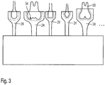
- Fig. 3 a further embodiment of the method according to the invention can be seen.
- numerous natural teeth 50 are molded and corresponding negative forms 54 are provided. This is done for the seven or eight teeth of each quadrant of a natural set of teeth, and also in different sizes, so that nature-identical negative shapes 54 are available in a tooth shape library.
- the corresponding nature-identical negative shape of the attachment 24 is then selected and used to provide the mold cavity 34 on the tooth to be treated.
- this method can be viewed as the realization of a tooth form key with shaping surfaces.
Description
- Die Erfindung betrifft ein Verfahren zur Herstellung eines Aufsatzes (24) oder Ansatzes eines Strahlungshärtgeräts gemäß dem Oberbegriff von Anspruch 1, ein Aufsatz oder Ansatz für ein Strahlungsgerät gemäß dem Oberbegriff von Anspruch 12 bzw. eine Dentalrestaurationserzeugnisvorrichtung gemäß dem Oberbegriff von Anspruch 13 zu schaffen, einer Dentalrestaurationserzeugungsvorrichtung, gemäß dem Oberbegriff von Anspruch 1, einen Aufsatz oder Ansatz gemäß dem Oberbegriff von Anspruch 12 sowie einer Dentalrestaurationserzeugungsvorrichtung gemäß dem Oberbegriff von Anspruch 13.
- Bei der Lichthärtung von lichthärtbaren Dentalrestaurationsmaterialien ist es wichtig, dass nach Möglichkeit die gesamte vom Lichthärtgerät erzeugte und aus dem Lichtleitstab austretende Strahlung dem Dentalrestaurationsmaterial zugeleitet wird. Während der Lichthärtung wird das Ende des Lichtleitstabs in den Mund des Patienten geführt, um gezielt an der Stelle, an der das Dentalrestaurationsmaterial vorliegt, die Lichthärtung vornehmen zu können. Bei versehentlicher Berührung kann die Spitze, also auch die Lichtaustrittsoberfläche, des Lichtleitstabs verschmutzen, was zu einer Verschlechterung der Lichtabgabe und gegebenenfalls zu einem unvollständig durchgehärteten und damit im Grunde unbrauchbaren Dentalrestaurationsteils führen kann.
- Aus der
DE 42 33 870 A1 ist eine Schutzhülle für ein Lichthärtgerät bekannt geworden, die das Ende des Lichtleitstabs vor Verschmutzungen schützen soll. - Diese Schutzhülle ist als Einmalprodukt ausgebildet und soll nach Gebrauch verworfen werden.
- Erfahrungsgemäß neigen Zahnärzte jedoch dazu, sparsam zu wirtschaften, und in der überwiegenden Anzahl der Fälle wird ein derartiges Einmalprodukt entgegen der Anwendungsanleitung nicht verworfen, sondern erneut verwendet, um eine Neubeschaffung zu vermeiden.
- Im besten Fall säubert der Zahnarzt vor der Zweitverwendung der Schutzhülle diese, wobei jedoch nicht sichergestellt ist, dass dies erfolgt bzw. dass die Säuberung perfekt ist.
- Das Ende des Lichtleitstabs ist typischerweise aus Glas und damit deutlich härter als das noch weiche Dentalrestaurationsmaterial. Wenn der Lichtleitstab versehentlich gegen das noch weiche Dentalrestaurationsmaterial gedrückt wird, verformt er dieses versehentlich, so dass die erwünschte Zahnoberfläche im Bereicht der Okklusionsfläche - oder gegebenenfalls auch im distalen Bereich dieser, aus welcher Richtung das Ende des Lichtleitstabs zum Dentalrestaurationsmaterial geführt wird - keineswegs mehr die gewünschte und exakt zu dem Antagonisten des zu behandelnden Zahns angepasste Gestaltung aufweist.
- Um ein derartiges versehentliches Verformen zu verhindern, ist es ebenfalls seit längerer Zeit, beispielsweise aus der
US 2004/0214130 A1 , bekannt geworden, eine flexible Schutzabdeckung zu verwenden, beispielsweise aus Polyurethan oder Silikon, die auch beim Berühren des noch weichen Dentalrestaurationsmaterials dieses nicht in schädlicher Weise verformen soll. - Jedoch ist es schwierig, die Härte des Silikons bzw. Polyurethans so gering einzustellen, dass keine Verformung erfolgt, zumal das ungehärtete Dentalrestaurationsmaterial gegebenenfalls auch sehr weich sein kann. Zwar ist gemäß der genannten Veröffentlichung eine Durometerhärte ab 40 vorgesehen. Auch bei einer solchen besteht die Möglichkeit, dass die Härte des noch weichen Dentalrestaurationsmaterials geringer ist, so dass sich nicht das weiche Vorsatzteil, sondern das Dentalrestaurationsmaterial verformt, mit den genannten nachteiligen Folgen.
- Insbesondere bei der Realisierung aus Polyurethan besteht zudem die Möglichkeit, dass durch den Kontakt zwischen dem weichen Dentalrestaurationsmaterial und der flexiblen Abdeckung das halbflüssige Dentalrestaurationsmaterial an der Abdeckung hängen bleibt und beim Lösen teilweise mit abgezogen wird, so dass weniger Dentalrestaurationsmaterial als beabsichtigt für die Lichthärtung zur Verfügung steht.
- Auch dies führt zu einer unzureichenden Realisierung des erwünschten Dentalrestaurationsteils.
- Demgegenüber ist es Aufgabe der Erfindung, ein Verfahren zur Herstellung eines Aufsatzes (24) oder Ansatzes einer Dentalrestaurationserzeugungsvorrichtung gemäß dem Oberbegriff von Anspruch 1 bzw. ein Aufsatz oder Ansatz gemäß dem Oberbegriff von Anspruch 12 sowie einer Dentalrestaurationserzeugungsvorrichtung gemäß dem Oberbegriff von Anspruch 13 zu schaffen, die es verhindert, dass das noch weiche Dentalrestaurationsmaterial in unerwünschter Weise durch Annäherung des Lichthärtgeräts beeinträchtigt wird.
- Diese Aufgabe wird erfindungsgemäß durch Anspruch 1, 12 bzw. 13 gelöst. Vorteilhafte Weiterbildungen ergeben sich aus den Unteransprüchen.
- Aus der Druckschrift
US 5,030,093 sind ein Verfahren und eine Vorrichtung zur Platzierung eines lichtaktivierbaren Dentalrestaurationsmaterials in eine Kavitätpräparation oder zwischen benachbarten Zähnen und zur Polymerisation des Dentalrestaurationsmaterials dort bekannt. Die dortige Vorrichtung weist ein Strahlungshärtgerät auf, an das abtrennbar ein Arbeitselement angeschlossen ist, das gegen eine herzustellende Dentalrestauration gehalten wird, um während der Härtung deren Form aufrechtzuerhalten. Jedoch ist die Herstellung der dortigen Dentalrestauration recht zeitraubend. - Die Druckschrift
DE 102 34 994 A1 offenbart eine Vorrichtung zur Anbringung einer Verblendung auf einen Zahn. Es ist dort ein Trägerelement aus Silikonkunststoff vorgesehen, das bei Bedarf zusammen mit einer Lichthärtungsvorrichtung zum Einsatz kommt. Demgegenüber ist es Aufgabe der Erfindung, ein Verfahren zur Herstellung eines Aufsatzes oder Ansatzes eines Strahlungshärtgeräts gemäß dem Oberbegriff von Anspruch 1, ein Aufsatz oder Ansatz für ein Strahlungsgerät gemäß dem Oberbegriff von Anspruch 12 bzw. eine Dentalrestaurationserzeugungsvorrichtung gemäß dem Oberbegriff von Anspruch 13 zu schaffen, eine Dentalrestaurationserzeugungsvorrichtung gemäß dem Oberbegriff von Anspruch 1 bzw. ein Aufsatz oder Ansatz gemäß dem Oberbegriff von Anspruch 17 zu schaffen, die es verhindert, dass das noch weiche Dentalrestaurationsmaterial in unerwünschter Weise durch Annäherung des Lichthärtgeräts beeinträchtigt wird. - Diese Aufgabe wird erfindungsgemäß durch Anspruch 1, 12 bzw. 13 gelöst. Vorteilhafte Weiterbildungen ergeben sich aus den Unteransprüchen.
- Erfindungsgemäß wird die Tatsache ausgenutzt, dass typischerweise Dentalrestaurationsteile computergestützt, also per CAD/CAM realisiert werden. Die Designphase verläuft in-sofern nach dem Intraoralscan im virtuellen Bereich auf dem Computer, und nach Festlegung der Außenform des Dentalrestaurationsteils ist es im Grunde in das Belieben des Anwenders gestellt, in welcher Weise das Dentalrestaurationsteil hergestellt werden soll. Beispielsweise erlauben die CAD-Daten die Konvertierung in Fräsdaten im Format STL, oder aber auch die Realisierung eines Positivmodells. Dieses wird dann vergossen, und nach Aushärten der Muffel aus dieser ausgeschmolzen. So wird ein Formhohlraum für die Bereitstellung eines Dentalrestaurationsteils aus Keramik oder Komposit geschaffen.
- Bei der Festlegung der Form des Dentalrestaurationsteils wird selbstverständlich auch die Form des Antagonisten berücksichtigt, aber es lassen sich auch gnathologische Gesichtspunkte einbinden, indem die sogenannte Funktionsabformung vorgenommen wird.
- Erfindungsgemäß werden nun die ohnehin vorhandenen Daten in überraschend einfacher Weise für die Erzeugung eines Lichthärtgerät-Aufsatzes oder -Ansatzes aus transparentem Material benutzt. Dieser Aufsatz oder Ansatz bildet erfindungsgemäß eine Negativform für das Dentalrestaurationsmaterial.
- Der Aufsatz oder Ansatz bildet damit gleichsam einen Stempel für die Formfestlegung des Dentalrestaurationsteils, der zum Einsatz gelangt, während das Dentalrestaurationsmaterial noch weich ist.
- Während bislang nach Möglichkeit ein Kontakt zwischen Lichthärtgerät und Dentalrestaurationsmaterial vermieden wurde, wird nun gerade der Kontakt gesucht und ausgenutzt.
- Im Unterschied zum Stand der Technik wird insofern der entgegengesetzte Weg gewählt, denn das Dentalrestaurationsmaterial ist vor Aushärtung stets weicher als der Aufsatz oder Ansatz. Überraschend entstehen damit gerade die im Stand der Technik bestehenden Probleme bei ähnlicher Weichheit nicht.
- In vorteilhafter Ausgestaltung ist der Aufsatz oder Ansatz aus Silikon oder auch einem beliebigen anderen, an dem Dentalrestaurationsmaterial nicht haftenden und transparenten Material.
- Erfindungsgemäß wird der Lichtleitstab während der gesamten Lichthärtzeit, die beispielsweise zwischen 5 und 30 Sekunden betragen kann, mit dem Dentalrestaurationsmaterial in Kontakt gehalten. In dieser Zeit härtet das Dentalrestaurationsmaterial von einer nahezu flüssigen Aggregatzustand in eine sehr festen Aggregatzustand durch.
- Überraschend ergibt sich mit der Erfindung ein weiterer besonderer Vorteil hinsichtlich der Lichthärtzeit. Durch den unmittelbaren Kontakt zwischen der Oberfläche des Dentalrestaurationsmaterials und dem Aufsatz oder Ansatz entfällt die Notwendigkeit, die für die Härtung verwendete Strahlung, die aus dem Lichtleitstab stammt, durch eine Luftstrecke hindurch schicken zu müssen. Es erfolgt eine unmittelbare Einleitung der Strahlung vom Ende des Lichtleitstabs in den Aufsatz oder Ansatz, und aus diesem heraus in das Dentalrestaurationsmaterial. Der Brechungsindex des Aufsatzes oder Ansatzes kann nun bevorzugt so gewählt sein, dass er zwischen denjenigen des Glases des Lichtleitstabs und demjenigen des Dentalrestaurationsmaterials in weichem Zustand liegt. Der Anteil der an den Übergangsoberflächen reduzierten Strahlung lässt sich damit deutlich, beispielsweise um eine Zehnerpotenz, reduzieren, denn hierdurch wird verhindert, dass zweimal ein optischer Übergang zwischen Materialien mit hohen und niedrigen Brechungsindex, geschaffen werden muss, mit den typischen Verlusten aufgrund der Reflexion bzw. Brechung an der Übergangsfläche.
- Dies bedeutet aber, dass mit deutlich geringeren Härtungszeiten ausgekommen werden kann, bei gleicher Eingangs-Lichtleistung.
- Es versteht sich, dass diese Gesichtspunkte nicht nur für die Lichthärtung, sondern auch für die Wärmehärtung gelten, wobei meist ohnehin ein gewisser Anteil der übertragenen Strahlung im Infrarotbereich liegt und insofern als Wärmestrahlung anzusehen ist.
- Der erfindungsgemäße Aufsatz oder Ansatz aus dem geeigneten Material wie beispielsweise Silikon lässt sich in einer vorteilhaften Ausgestaltung beispielsweise per 3D-Druck oder per Fräsen oder per Gießen herstellen. Der Silikonaufsatz bildet dann die Negativform für die erwünschte Zahnkontur. Diese lässt sich in an sich bekannter Weise aus der mittels eines Interdentalscanners erfassten Kontur ableiten und besteht als Negativform für die Oberfläche des Zahns nach Aufbringen des Dentalrestaurationsteils.
- Bei dieser Ausführungsform ist der Aufsatz oder Ansatz ein Einmalteil, das jedoch patientenspezifisch ist, so dass die Wiederverwendung ausgeschlossen ist.
- Erfindungsgemäß ergibt sich zudem, dass das Polieren durch die glatte Oberfläche des Aufsatzes oder Ansatzes entfallen kann, oder jedenfalls vereinfacht wird.
- In einer weiteren Ausführungsform ist es vorgesehen, den Aufsatz oder Ansatz mit einer Negativgrundform für die Kompositmodellierung zu realisieren. Die Grundform ist menschlichen Zähnen nachempfunden, und es ist möglich, mit geringem Aufwand die je patientenspezifische Form dort zu modellieren, wobei die erwünschte Form des Dentalrestaurationsteils dann in einem Zuge ausgehärtet werden kann.
- Eine weitere Variante der Erstellung der Oberfläche des Aufsatzes oder Ansatzes bezieht den Antagonisten ein. Bei dieser Lösung wird zunächst der noch nicht durchgehärtete Aufsatz oder Ansatz an den Antagonisten gehalten. Das Lichthärtgerät wird eingeschaltet und dann damit der Aufsatz oder Ansatz mindestens teilweise gehärtet. Die so erzeugte Negativoberfläche für das Dentalrestaurationsmaterial wird dann als Negativform für das Dentalrestaurationsmaterial - gegebenenfalls nach einer gewissen Bearbeitung - verwendet, so dass automatisch eine passende Okklusionsfläche bei dem zu behandelnden Zahn erzeugt wird.
- Eine weitere Möglichkeit besteht darin, gleichsam eine Negativformbibliothek für naturidentische Negativformen von allen natürlichen Zähnen bereitzuhalten. Entsprechende Negativformen bestehen dann für jeden Zahn in der entsprechenden Grundform, aber auch in verschiedenen Größen. Hierdurch lässt sich ein Negativform-Zahnformschlüssel für das gesamte menschliche Gebiss bereitstellen.
- Es ist auch möglich, dass Dentalrestaurationsmaterial in den Formhohlraum, der zwischen dem Restzahn und dem Aufsatz oder Ansatz gebildet ist, einzubringen. Hierzu weist der Aufsatz oder Ansatz einen Einlasskanal für Dentalrestaurationsmaterial auf, das dann beispielsweise mit einer Spritze eingebracht wird. Bei dieser Lösung ist es günstig, wenn darauf geachtet wird, dass die im Formhohlraum befindliche Luft dann entweichen kann. Dies geschieht bevorzugt über einen porösen Luftauslass, der das Austreten von Luft ermöglicht, aber das Hindurchtreten von Dentalrestaurationsmaterial verhindert. Bei dieser Lösung ist sichergestellt, dass kein Überschuss an Dentalrestaurationsmaterial besteht, so dass das aufwendige Entfernen von Randwülsten, wie es bei Kompositmaterial üblich ist, entfallen kann.
- Es versteht sich, dass sowohl der Einlasskanal als auch der Luftauslass nicht im Strahlungsbereich liegen sollten. Beide können beispielsweise seitlich angeordnet sein, bevorzugt einander gegenüberliegend. Der Einlasskanal kann auch durch einfaches Durchstechen des Aufsatzes oder Ansatzes seitlich mit einer Spritze mit dem Dentalrestaurationsmaterial geschaffen werden. Der Formhohlraum wird dann mittels der Spritze befüllt, bis ein Gegendruck entsteht, der anzeigt, dass der Formhohlraum vollständig mit Dentalrestaurationsmaterial gefüllt ist.
- Bevorzugt ist der Luftauslass in einem oberen Bereich des Formhohlraums angeordnet, um so jedenfalls sicherzustellen, dass keine Luftbläschen verbleiben, die dann nachgefüllt werden müssten.
- Durch geschickte Anordnung des Luftauslasses kann die verbleibende Luft im Formhohlraum jedenfalls vollständig entweichen.
- Der Aufsatz oder Ansatz ist jedenfalls sicher und unverlierbar auf dem vorderen Ende des Lichtleitstabs des Lichthärtgeräts befestigt. Um die Unterbrechung des Lichtstrahls durch eine dazwischenliegende Luftschicht zu vermeiden, ist es möglich, die Oberfläche des Lichtleitstabs vor Aufbringen des Aufsatzes oder Ansatzes mit einer geeigneten Flüssigkeit zu benetzen, so dass ein luftfreier Strahlungsübergang zwischen dem Austrittsende des Lichtleitstabs und dem Aufsatz oder Ansatz gewährleistet ist.
- Der Aufsatz oder Ansatz kann im Grunde eine beliebige Form aufweisen. Bevorzugt umgibt er das vordere Ende des Lichtleitstabs vollständig und erstreckt sich dann - sich gegebenenfalls etwas verjüngernd oder erweiternd - zu der Negativformoberfläche des Aufsatzes oder Ansatzes hin, wobei diese Fläche jedenfalls den Bereich aufzubringenden Dentalmaterials vollständig abdeckt.
- Bevorzugt ist der Überlappungsrand zu dem gesunden Zahn so gewählt, dass eine Minimalbreite nicht unterschritten wird, die mindestens 1 mm, bevorzugt aber 2 mm oder 3 mm betragen sollte. Hierdurch lässt sich ein Druck zwischen Lichthärtgerät und Zahn ausüben, ohne dass der Aufsatz oder Ansatz verformt würde. Dieser Druck dient zugleich der Abstützung, so dass sichergestellt ist, dass der Zahnarzt bei der Behandlung keine Schwierigkeiten hat, das Lichthärtgerät ruhig zu halten, zumindest in der nunmehr noch geringeren Aushärtzeit.
- Es ist auch günstig, wenn der Aufsatz oder Ansatz aus hochtransparentem Material gestaltet ist. Hierdurch wird die aufgebrachte Strahlungsenergie nicht oder nicht merklich reduziert. Zudem kann der Aufsatz oder Ansatz im Grunde als ein massiver Körper ausgebildet sein, der in seinem Mittelbereich ausgesprochen stabil ist und lediglich dessen Enden hülsenförmig aufgeweitet sind, zum einen zur Umfassung des Endes des Lichtleitstabs, und zum anderen zum Abstützen an den gesunden Bereichen des zu behandelnden Zahnes.
- Gemäß einer vorteilhaften Ausgestaltung ist ein zusätzlich beigefügter und wiederverwendbarer Adapterring vorgesehen. Der Adapterring ist dann sinnvoll, wenn der Typ des zu verwendenden Lichthärtgeräts nicht von vorne herein bekannt ist. Wenn beispielsweise Lichthärtgeräte mit einem Lichtleitstabdurchmesser von 8 mm, 10 mm oder 12 mm zu Einsatz kommen können, lässt sich bevorzugt die Aufnahmeöffnung für das vordere Ende des Lichtleitstabs, die wie ein Sackloch ausgebildet ist, in dem größten zu erwartenden Durchmesser, also hier 12 mm, herstellen. Wenn nun ein Lichthärtgerät mit einem Lichtleitstab von 10 mm eingesetzt wird, wird ein Adapterring mit 1 mm Wandstärke eingesetzt, der den ansonsten bestehenden Ringspalt zwischen der Aufnahmeausnehmung des Aufsatzes oder Ansatzes und dem vorderen Ende des Lichtleitstabs ausfüllt. Bei Einsatz eines Lichthärtgeräts mit einem Lichtleitstabdurchmesser von 8 mm wird dementsprechend ein Adapterring mit 2 mm Wandstärke eingesetzt.
- Dieses Verfahren ist besonders dann günstig, wenn der Aufsatz oder Ansatz in einem zentralen Dentallabor erzeugt und dem Zahnarzt dann zur Verfügung gestellt wird. Das Dentallabor muss dann nicht die Zusatzinformation erhalten, welcher Durchmesser des Lichtleitstabs zum Einsatz gelangen soll.
- Wenn hingegen ein 3D-Druck vor Ort, also in der Zahnarztpraxis erfolgt, was üblicherweise als "Chairside"-Lösung bezeichnet wird, weiss der Zahnarzt meist, welches Lichthärtgerät eingesetzt werden soll, so dass der Adapterring entbehrlich ist.
- In vorteilhafter Ausgestaltung ist es vorgesehen, dass die Aufnahmeausnehmung für das vordere Ende des Lichtleitstabs gegenüber dem Außendurchmesser des Lichtleitstabs ein gewisses Untermaß hat. Über eine gegebenenfalls vorhandene Einführschräge lässt sich der Lichtleitstab dennoch in die Aufnahmeausnehmung einführen, da das Material des Aufsatzes oder Ansatzes typischerweise etwas elastisch ist und bei Realisierung eines Untermaßes spielfrei auf dem Lichtleitstab sitzt.
- Weitere Vorteile, Einzelheiten und Merkmale ergeben sich aus der nachfolgenden Beschreibung mehrerer Ausführungsbeispiele der Erfindung anhand der Zeichnungen.
- Es zeigen:
- Fig. 1
- eine schematische Ansicht einer erfindungsgemäßen Dentalrestaurationserzeugungsvorrichtung in einer Ausführungsform;
- Fig. 2
- eine schematische Darstellung einer weiteren Ausführungsform einer Dentalmaterialerzeugungsvorrichtung; und
- Fig. 3
- eine schematische Darstellung einer weiteren Ausführungsform einer Dentalmaterialerzeugungsvorrichtung.
- Eine Dentalmaterialerzeugungsvorrichtung 10, wie sie in
Fig. 1 dargestellt ist, weist ein Strahlungshärtgerät 12 auf, von dem ein Lichtleitstab 14 in seinem vorderen Teil dargestellt ist. Der Lichtleitstab 14 weist ein vorderes Ende 16 auf, das mit einer Lichtaustrittsfläche 18 endet. Der Lichtleitstab 14 weist ein Emissionsspektrum auf, das auf den oder die Photoinitiatoren von Dentalrestaurationsmaterial 20 abgestimmt ist, das dazu dient, ein Dentalrestaurationsteil 22 zu erzeugen. - Erfindungsgemäß ist ein Aufsatz 24 vorgesehen, der auf dem Ende 16 des Lichtleitstabs 14 aufgesteckt ist.
- In einem alternativen, hier nicht dargestellten Ausführungsbeispiel, ist anstelle eines Aufsatzes 24 ein Ansatz vorgesehen, der sich lediglich nach vorne von der Lichtaustrittsfläche 18 weg erstreckt und mit dem das vordere Ende 16 des Lichtleitstabs 14 in Kontakt gebracht werden kann.
- Erfindungsgemäß wesentlich ist es, dass die von dem Strahlungshärtgerät 12 abgegebene Strahlungsleistung, wie sie an der Lichtaustrittsfläche 18 vorliegt, vollständig oder zumindest mit einem sehr hohen Wirkungsgrad wie 99 % in den Aufsatz 24 eingeleitet wird. Der Aufsatz 24 weist hierzu eine Aufnahmeausnehmung 26 auf, die für das Ende 16 bestimmt ist. Die Aufnahmeausnehmung 26 ist im Wesentlichen sacklochförmig und weist einen planen Boden auf, dessen Form exakt auf die Form der Lichtaustrittsfläche 18 abgestimmt ist. Bevorzugt ist eine geeignete Flüssigkeit als Dünnschicht vorgesehen, die den gleichen Brechnungsindex wie der Aufsatz 24 aufweist und über die ein luftfreier optischer Übergang zwischen der Luftaustrittsfläche 18 und dem Aufsatz 24 geschaffen wird.
- Der Aufsatz 24 besteht aus Silikon, bevorzugt einen hochtransparenten Silikon und ist in besonderer Weise geformt.
- Anschließend an die Aufnahmeausnehmung 26 verläuft der Aufsatz 24 ballig bzw. nahezu tropfenförmig und erstreckt sich insofern von dem Ende 16 weg.
- Der Aufsatz 24 ist dafür bestimmt, an einem Zahn 30 angelegt zu werden, und zwar so, dass das dort vorliegende, aber noch ungehärtete und daher weiche Dentalrestaurationsmaterial 20 vollständig umgeben ist. Hierzu dichtet der Aufsatz 24 gegenüber dem Zahn 30 mit einer Ringfläche 32, die dreidimensional gestaltet und an die Zahnoberfläche angepasst ist, gegenüber dem Zahn ab. Die Breite der Ringfläche beträgt überall mehr als 1 mm und bevorzugt 2 mm bis 3 mm. Hierdurch ist sichergestellt, dass sich Abstützkräfte zwischen dem Strahlungshärtgerät 12 und dem Zahn 30 sicher auffangen lassen, ohne dass der Aufsatz 24 nennenswert verformt ist.
- Aufgrund der Materialwahl Silikon besteht eine gewisse Elastizität des Aufsatzes 24. Die Elastizität kommt der Klemmwirkung des Aufsatzes 24 an dem Ende 16 zu Gute. Beispielsweise kann die Aufnahmeausnehmung 26 mit einem gewissen Untermaß gegenüber dem Durchmesser des Endes 16 gefertigt sein und klemmt daher auf diesem.
- Der Aufsatz 24 ist an seiner dem Zahn 30 zugewandten, und insofern distalen Seite in besonderer Weise ausgebildet. Er ist durch eine CAD-Vorrichtung in seiner Form festgelegt. Hierzu wird zunächst nach einem Intraoralscann des Mundes des Patienten eine Oberflächenform für den zu restaurierenden Zahn per CAD festgelegt. Basierend hierauf wird der Aufsatz 24 als Negativform mit einer der Dentalrestaurationsoberfläche zugewandten Formungsoberfläche gefertigt. Er bildet insofern gleichsam den oberen Abschluss für einen Formhohlraum 34, der sich zwischen der Oberfläche des Restzahnes 30 und dem Aufsatz 24 ergibt. Seine Oberfläche ist entsprechend der gewünschten Form der Zielform des Dentalrestaurationsteils gestaltet.
- Das Dentalrestaurationsmaterial 20 wird in den Formhohlraum 34 in beliebiger geeigneter Weise eingebracht, und zwar in weichem, also ungehärtetem Zustand. Dies kann entweder als eine Art Tropfen geschehen, der auf den Restzahn 30 aufgebracht wird. Alternativ kann auch eine der Seitenflanken entsprechend der Linie 36 kurzerhand mit einer Spritze durchstochen werden und über diese das Dentalmaterial 20 in den bereits bestehenden Formhohlraum eingebracht werden. An einer gegenüberliegenden Seite, die hier mit 38 bezeichnet ist, ist ein Luftauslasskanal vorgesehen, der beim Befüllen des Formhohlraums 34 den Austritt von Luft ermöglicht. Der Luftauslasskanal 28 mündet in den Formhohlraum 34 nahezu an dessen höchster Stelle, so dass es nicht zu erwarten ist, dass dort Luftblasen verbleiben.
- Der Luftauslasskanal 38 ist bevorzugt mit einem durchsichtigen, aber porösen Material gefüllt, das den Eintritt und Durchtritt von Dentalrestaurationsmaterial 20 verhindert.
- Für die Bereitstellung der Dentalrestauration wird nun zunächst das Strahlungshärtgerät 12 mit dem Aufsatz 24 passend zu dem je zu restaurierenden Zahn bestückt. Der Aufsatz 24 wird nun auf den Zahn 30 aufgedrückt, und zwar so, dass ein sicherer Formschluss und auch eine Abdichtung gegeben ist. In dem vorliegenden Ausführungsbeispiel ist bewusst eine Seitenflanke 40 des Aufsatzes 24 so ausgestaltet, dass sie bis zu einem Gegenhöcker 42 der Okklusionsfläche 44 des Zahns 30 reicht und sich dort sicher abstützen kann. Damit hat der behandelnde Zahnarzt auch gleich eine Gegenstützfläche bei der Handhabung des Strahlungshärtgeräts 12, so dass nicht nur die translatorische, sondern auch die Winkelausrichtung des Aufsatzes 24 gegenüber dem zu restaurierenden Zahn 30 vorgegeben ist.
- Nachdem die optimale Restaurationsposition des Aufsatzes 24 gefunden ist, bringt der Zahnarzt über eine an sich bekannte Spritze das Dentalrestaurationsmaterial 20 in den Formhohlraum 34 ein, bis er einen Widerstand spürt. Der Eindringwiderstand bedeutet, dass der Formhohlraum 34 gefüllt ist und dass überschüssiges Dentalrestaurationsmatrial durch die Filterfuktion des Luftauslasses 38 blockiert wird.
- Sobald dies wahrgenommen wird, wird die Spritze mit dem flüssigen Dentalrestaurationsmaterial entfernt. Aufgrund der Nachgiebigkeit des Silikons schließt sich dann der Einlasskanal 36 für das Dentalrestaurationsmaterial selbsttätig.
- Das Strahlungshärtgerät wird für eine vorgegebene Härtungsperiode eingeschaltet, die der Dicke des Dentalrestaurationsmaterials 20 entspricht und sicherstellt, dass die Durchhärtung erfolgt.
- Der Strahlungsdurchgang erfolgt praktisch umlenkungsfrei und insbesondere reflexionsarm vom Ende 16 in den Aufsatz 24 und dann in das Dentalrestaurationsmaterial 20 hinein. Hierbei ist es besonders günstig, dass die Brechnungsindizes des Glases des Lichtleitstabs 14, des Aufsatzes 24 und des Dentalrestaurationsmaterials 20 sich voneinander nur um ein geringeren Wert unterscheiden. Das Dentalrestaurationsmaterial 20 liegt im Bereich der Negativform oder der Formungsoberfläche unmittelbar an dem Aufsatz 24 an, so dass auch dort kein Luftspalt besteht und dementsprechend praktisch keine Brechung der übertretenden Strahlung.
- Aufgrund des hier günstigen Eintrittswinkels der Strahlung über das Ende 16 in das Dentalrestaurationsmaterial 20 hinein wird zudem die Strahlung vom zahnseitigen bzw. gingivalen Boden des Formhohlraums 34 reflektiert und trägt weiter zur Durchhärtung bei.
- Insgesamt führt die insofern optimierte Realisierung des Strahlungsverlaufs dazu, dass sich die Belichtungsdauer gegenüber den an sich bekannten luftgebundenen Dentalrestaurationserzeugungsvorrichtungen um 20 % bis 40 % reduzieren lässt.
- Nach Abschluss der Durchhärtung wird der Aufsatz 24 zusammen mit dem Strahlungshärtgerät 12 entfernt, und es verbleibt das fertige, bereits geglättete Dentalrestaurationsteil. Das Dentalrestaurationsteil 22 weist typischerweise keinen Ringwulst auf, der entfernt werden müsste, vorausgesetzt, an der Ringfläche 32 erfolgt die gewünschte Abstützung und Abdichtung.
- Ferner ist ein Polieren aufgrund der Glättung durch den Aufsatz 24 nicht erforderlich, oder nur in ganz geringem Maße.
- Aus
Fig. 2 ist eine weitere Ausführungsform einer erfindungsgemäßen Dentalrestaurationsvorrichtung ersichtlich. Gleiche Bezugszeichen weisen hier wie auch in der weiteren Figur auf gleiche oder entsprechende Teil hin. - Bei dem anhand von
Fig. 2 zu erläuternden Verfahren wird zunächst ein weicher, also ungehärteter Aufsatz 24 bereitgestellt. Dieser wird an einen Antagonisten 50 angedrückt, so dass sich an einer Oberfläche 52 eine Negativform 54 ergibt. Dieser Abdruck des Aufsatzes 24 auf dem Antagonisten 50 wird nun zunächst über das Strahlungshärtgerät 12 gehärtet. Der Aufsatz 24 wird dann von dem Antagonisten 50 abgenommen und umgedreht, so dass sich die Negativform 54 zum Zahn 30 erstreckt. - Diese wird nun als oberer Abschluss des mit Dentalrestaurationsmaterial 20 gefüllten Formhohlraums 34 verwendet. An den Aufsatz 24, der hier eher als Ansatz ausgebildet ist, wird nun das Ende 16 des Lichtleitstabs 14 des Strahlungshärtgeräts 12 aufgedrückt, und zwar oberhalb der Negativform 54. Dies ist in
Fig. 2 gestrichelt angedeutet. Dann wird das Lichthärten vorgenommen, so dass sich für den Zahn 30, der das fertige Dentalrestaurationsteil 22 aufweist, eine zu dem Antagonisten 50 passende Form ergibt. - Aus
Fig. 3 ist eine weitere Ausführungsform des erfindungsgemäßen Verfahrens ersichtlich. Zunächst werden zahlreiche natürliche Zähne 50 abgeformt und entsprechende Negativformen 54 bereitgestellt. Dies erfolgt für die sieben oder acht Zähne jedes Quadranten eines natürlichen Gebisses, und zudem in unterschiedlichen Größen, so dass im Rahmen einer Zahnformbibliothek naturidentische Negativformen 54 vorliegen. - Die entsprechende naturidentische Negativform des Aufsatzes 24 wird dann ausgewählt und für die Bereitstellung des Formhohlraums 34 an dem je zu behandelnden Zahn verwendet.
- Insofern kann dieses Verfahren als die Realisierung eines Zahnformschlüssels mit Formungsoberflächen betrachtet werden.
Claims (13)
- Verfahren zur Herstellung eines Aufsatzes (24) oder Ansatzes eines Strahlungshärtgeräts, der dem Dentalrestaurationsmaterial (20) zugewandt ist oder auf dieses richtbar ist, für eine Dentalrestaurationserzeugungsvorrichtung, umfassend härtbares Dentalrestaurationsmaterial (20), ein Strahlungshärtgerät, mit welchem mittels Lichtstrahlung, UV-Strahlung und/oder Wärmestrahlung das härtbare Dentalrestaurationsmaterial (20) zur Erzeugung eines Dentalrestaurationsteils (22) aushärtbar ist, dadurch gekennzeichnet, dass der Aufsatz oder Ansatz (24), der eine Formungsoberfläche aufweist, die der Zielform der Oberfläche (52) des Dentalrestaurationsmaterials (20) entspricht und eine Negativform (54) für dieses an dem dem Strahlungshärtgerät zugewandten Bereich bildet, an seiner distalen Seite durch eine CAD-Vorrichtung in seiner Form festgelegt wird, insbesondere basierend auf den Daten, die der Außenform des Dentalrestaurationsteils (22) entsprechen und dass der Aufsatz (24) oder Ansatz aus einem geeigneten Material, insbesondere aus Silikon, mittels eines formgebenden Verfahrens, insbesondere 3D-Druck, Fräsen oder Gießen, zur Darstellung einer Negativform für die erwünschte Zahnkontur, hergestellt wird.
- Verfahren nach Anspruch 1, dadurch gekennzeichnet dass der Aufsatz (24) oder Ansatz aus einem transparenten Material ausgebildet wird und an dem Strahlungshärtgerät im übrigen angebracht wird.
- Verfahren nach Anspruch 1, dadurch gekennzeichnet, dass der Aufsatz (24) oder Ansatz aus einem vorab, also vor der Härtung, vorverformbaren und ebenfalls härtbaren Material hergestellt wird.
- Verfahren nach einem der vorhergehenden Ansprüche, dadurch gekennzeichnet, dass der Aufsatz (24) oder Ansatz so gestaltet wird, dass er an den Seitenflanken (42) im wesentlichen eine Kegelform oder eine Kegelstumpfform aufweist.
- Verfahren nach einem der vorhergehenden Ansprüche, dadurch gekennzeichnet, dass der Aufsatz (24) oder Ansatz so gestaltet wird, dass er kraft- und/oder formschlüssig an dem Strahlungshärtgerät im übrigen befestigt wird und dass über diesen Druck auf das noch weiche Dentalrestaurationsmaterial (20) ausübbar ist.
- Verfahren nach einem der vorhergehenden Ansprüche, dadurch gekennzeichnet, dass der Aufsatz (24) oder Ansatz per dreidimensionalem Druck erzeugt wird und seine dem Dentalrestaurationsmaterial (20) zugewandte Oberfläche (52) eine Negativform (54) für das Dentalrestaurationsmaterial (20) bildet, die für die Erzeugung eines Abdrucks nach der Art eines Stempels in dem Dentalrestaurationsmaterial (20) bestimmt ist.
- Verfahren nach einem der vorhergehenden Ansprüche, dadurch gekennzeichnet, dass der Aufsatz (24) oder Ansatz lösbar an einem Lichtleiter des Strahlungshärtgeräts befestigt wird und insbesondere als Einmalprodukt gestaltet wird.
- Verfahren nach einem der vorhergehenden Ansprüche, dadurch gekennzeichnet, dass der Aufsatz (24) oder Ansatz so gestaltet wird, dass er eine feste mit dem Lichtleiter des Strahlungshärtgeräts verbundene Grundform aufweist, die einer typischen Grundform menschlicher Zähne, beispielsweise deren Okklusionsfläche (44), nachempfunden ist, und auf welcher die erforderlichen Strukturen in transparentem Material modellierbar sind.
- Verfahren nach einem der vorhergehenden Ansprüche, dadurch gekennzeichnet, dass eine Abdruckmasse vorgesehen ist, über welche ein Abdruck des Antagonisten (50) des Zahnes (30) mit dem Dentalrestaurationsmaterial (20) nehmbar wird und dass die Abdruckmasse nach ihrer Härtung für die Formfestlegung des Aufsatzes (24) oder Ansatzes eingesetzt wird.
- Verfahren nach einem der vorhergehenden Ansprüche, dadurch gekennzeichnet, dass eine Vielzahl von Aufsätzen oder Ansätzen entsprechend den natürlichen menschlichen Zähnen als Negativformen (54) hergestellt werden, welche nach der Art eines Stempels auf das Dentalrestaurationsmaterial (20) je nach erwünschter Zahnposition drückbar und zur Formung des Dentalrestaurationsmaterials (20) verwendbar sind.
- Verfahren nach einem der vorhergehenden Ansprüche, dadurch gekennzeichnet, dass der Aufsatz (24) oder Ansatz so gestaltet wird, dass er eine Aufnahme für das vordere Ende (16) eines Lichtleiters aufweist, welche Aufnahme über einen Flansch kraftschlüssig auf dem vorderen Ende (16) des Lichtleiters befestigbar ist.
- Aufsatz oder Ansatz für ein Strahlungshärtgerät, dadurch gekennzeichnet, dass er nach dem Verfahren nach Anspruch 1 hergestellt ist, so dass er eine Formungsoberfläche für ein Dentalrestaurationmaterial aufweist.
- Dentalrestaurationserzeugungsvorrichtung, umfassend härtbares Dentalrestaurationsmaterial (20), ein Strahlungshärtgerät, mit welchem mittels Lichtstrahlung, UV-Strahlung und/oder Wärmestrahlung das härtbare Dentalrestaurationsmaterial (20) zur Erzeugung eines Dentalrestaurationsteils (22) aushärtbar ist, und einen Aufsatz (24) oder Ansatz des Strahlungshärtgeräts, der dem Dentalrestaurationsmaterial (20) zugewandt ist oder auf dieses richtbar ist, dadurch gekennzeichnet, dass der Ansatz oder Aufsatz (24) nach dem Verfahren nach Anspruch 1 hergestellt, so dass er eine Formungsoberfläche aufweist, die der Zielform der Oberfläche (52) des Dentalrestaurationsmaterials (20) entspricht und eine Negativform (54) für dieses an dem dem Strahlungshärtgerät zugewandten Bereich bildet.
Priority Applications (3)
| Application Number | Priority Date | Filing Date | Title |
|---|---|---|---|
| EP16173538.6A EP3254641B1 (de) | 2016-06-08 | 2016-06-08 | Verfahren zur herstellung eines aufsatzes oder ansatzes eines strahlungshärtgeräts, aufsatz oder ansatz und dentalrestaurationserzeugungsvorrichtung |
| PCT/EP2017/062559 WO2017211588A1 (de) | 2016-06-08 | 2017-05-24 | Dentalrestaurationserzeugungsvorrichtung sowie aufsatz oder ansatz |
| US16/306,695 US11051922B2 (en) | 2016-06-08 | 2017-05-24 | Dental restoration production device and add-on or attachment |
Applications Claiming Priority (1)
| Application Number | Priority Date | Filing Date | Title |
|---|---|---|---|
| EP16173538.6A EP3254641B1 (de) | 2016-06-08 | 2016-06-08 | Verfahren zur herstellung eines aufsatzes oder ansatzes eines strahlungshärtgeräts, aufsatz oder ansatz und dentalrestaurationserzeugungsvorrichtung |
Publications (2)
| Publication Number | Publication Date |
|---|---|
| EP3254641A1 EP3254641A1 (de) | 2017-12-13 |
| EP3254641B1 true EP3254641B1 (de) | 2020-12-09 |
Family
ID=56116324
Family Applications (1)
| Application Number | Title | Priority Date | Filing Date |
|---|---|---|---|
| EP16173538.6A Active EP3254641B1 (de) | 2016-06-08 | 2016-06-08 | Verfahren zur herstellung eines aufsatzes oder ansatzes eines strahlungshärtgeräts, aufsatz oder ansatz und dentalrestaurationserzeugungsvorrichtung |
Country Status (3)
| Country | Link |
|---|---|
| US (1) | US11051922B2 (de) |
| EP (1) | EP3254641B1 (de) |
| WO (1) | WO2017211588A1 (de) |
Families Citing this family (4)
| Publication number | Priority date | Publication date | Assignee | Title |
|---|---|---|---|---|
| WO2020084533A1 (en) * | 2018-10-25 | 2020-04-30 | 3M Innovative Properties Company | 3d-printed dental restoration precursor with support element and process of production |
| US11304788B2 (en) * | 2019-11-07 | 2022-04-19 | Orthosnap Corp. | Light concentrating adapter for dental curing |
| WO2021219228A1 (en) * | 2020-04-30 | 2021-11-04 | Rayo 3D-Toothfill Oy | Preparation of a restorative object |
| FR3120784A1 (fr) * | 2021-03-17 | 2022-09-23 | Dong Vu | Dispositif médical sur mesure pour restaurer l’anatomie occlusale d’une dent |
Family Cites Families (9)
| Publication number | Priority date | Publication date | Assignee | Title |
|---|---|---|---|---|
| SE435447B (sv) * | 1983-02-21 | 1984-10-01 | Dan Ericson | Sett och anordning for framstellning av en tandfyllning av ljusherdande material |
| US5030093A (en) * | 1988-06-10 | 1991-07-09 | Aaron Teitelbaum | Method and apparatus for dental restorative material |
| DE4233870A1 (de) | 1992-10-08 | 1994-04-14 | Heraeus Kulzer Gmbh | Schutzvorrichtung für ein medizinisches Bestrahlungsgerät |
| DE10234994A1 (de) * | 2002-07-31 | 2004-02-12 | Gerhard Bruckner | Zahnverblendung und Vorrichtung zur Aufbringung einer Zahnverblendung |
| US20040214130A1 (en) | 2003-04-25 | 2004-10-28 | Ultradent Products, Inc. | Flexible translucent protective covers used to protect dental appliances from rigid light emitting devices |
| US7217131B2 (en) * | 2004-11-26 | 2007-05-15 | Vuillemot William C | Method for dental restoration and kit |
| US20100193549A1 (en) * | 2008-10-24 | 2010-08-05 | James Ronald Sirkis | Container for storing and dispensing a flowable material |
| US8753114B2 (en) * | 2010-02-26 | 2014-06-17 | William C. Vuillemot | Method for dental restoration and related kit |
| US10327873B2 (en) * | 2014-10-27 | 2019-06-25 | 3Shape A/S | Method, system and user interface for creating a digital design for use in manufacturing a molding-shell for a dental restoration |
-
2016
- 2016-06-08 EP EP16173538.6A patent/EP3254641B1/de active Active
-
2017
- 2017-05-24 US US16/306,695 patent/US11051922B2/en active Active
- 2017-05-24 WO PCT/EP2017/062559 patent/WO2017211588A1/de active Application Filing
Non-Patent Citations (1)
| Title |
|---|
| None * |
Also Published As
| Publication number | Publication date |
|---|---|
| US20190117358A1 (en) | 2019-04-25 |
| US11051922B2 (en) | 2021-07-06 |
| EP3254641A1 (de) | 2017-12-13 |
| WO2017211588A1 (de) | 2017-12-14 |
Similar Documents
| Publication | Publication Date | Title |
|---|---|---|
| DE60022506T2 (de) | Endodontisches stiftsystem | |
| EP3254641B1 (de) | Verfahren zur herstellung eines aufsatzes oder ansatzes eines strahlungshärtgeräts, aufsatz oder ansatz und dentalrestaurationserzeugungsvorrichtung | |
| EP2862539B1 (de) | Dentale Transferschablone | |
| EP2144574B1 (de) | Handgerät zur abgabe eines pastösen füllungsmaterials | |
| EP2952154B1 (de) | Verfahren zur Herstellung mehrerer Dentalrestaurationen sowie Dentalkeramik-Erzeugungsvorrichtung | |
| DE112007001376T5 (de) | Orthodontisches Indirektklebtray mit Feuchtigkeitskontrolle | |
| EP3649983A1 (de) | Dentalprothesen-herstellverfahren | |
| EP1901676B1 (de) | Verfahren und materialsatz zum herstellen von zahnersatzteilen | |
| EP2952155B1 (de) | Dentalkeramik-Erzeugungsvorrichtung | |
| WO2014001556A1 (de) | Verfahren zur herstellung eines zahnersatzes | |
| EP3572035B1 (de) | Dentalprothese, zugehöriges halbprodukt sowie bausatz | |
| EP2378996A2 (de) | Interdentalvorrichtung | |
| DE102018123318A1 (de) | Vorprodukt zur Herstellung von Prothesenzähnen und Verfahren zu dessen Herstellung und Verarbeitung | |
| DE102015106424A1 (de) | Verfahren zur Herstellung von Zahnersatz mit einem Kunststoffkern | |
| EP3157460B1 (de) | Prothesenbasis sowie verfahren zur stoffschlüssigen verbindung mindestens eines künstlichen zahns mit einer prothesenbasis | |
| DE10234994A1 (de) | Zahnverblendung und Vorrichtung zur Aufbringung einer Zahnverblendung | |
| EP3525718A1 (de) | In wachs eingebetteter vorgeformter prothesenbasisrohling | |
| EP3612130A1 (de) | Wiederverwendbares, zahnmedizinisches materialträgermodul und ein wiederverwendbares, zahnmedizinisches materialträger-system, aus sets von materialträgermodulen und verfahren | |
| DE19513568C1 (de) | Präparationsschleifer-Inlay-System | |
| DE102021112178B4 (de) | Verfahren und Vorrichtung zur Herstellung einer Dentalprothese | |
| DE102008011447A1 (de) | Formvorrichtung und Verfahren zum Herstellen einer Heilkappe, sowie Set und Heilkappe | |
| DE102005016763A1 (de) | Set zur Herstellung einer provisorischen Zahnkrone oder -brücke | |
| EP3056165B1 (de) | Zahnmedizinische vorrichtung mit übertragungsschale | |
| DE19512625C2 (de) | Präparationsschleifer-Inlay-System | |
| DE102014113945B4 (de) | Verfahren zur Herstellung einer Sekundärkappe in einem Zahnimplantat |
Legal Events
| Date | Code | Title | Description |
|---|---|---|---|
| PUAI | Public reference made under article 153(3) epc to a published international application that has entered the european phase |
Free format text: ORIGINAL CODE: 0009012 |
|
| STAA | Information on the status of an ep patent application or granted ep patent |
Free format text: STATUS: THE APPLICATION HAS BEEN PUBLISHED |
|
| AK | Designated contracting states |
Kind code of ref document: A1 Designated state(s): AL AT BE BG CH CY CZ DE DK EE ES FI FR GB GR HR HU IE IS IT LI LT LU LV MC MK MT NL NO PL PT RO RS SE SI SK SM TR |
|
| AX | Request for extension of the european patent |
Extension state: BA ME |
|
| STAA | Information on the status of an ep patent application or granted ep patent |
Free format text: STATUS: REQUEST FOR EXAMINATION WAS MADE |
|
| 17P | Request for examination filed |
Effective date: 20180508 |
|
| RBV | Designated contracting states (corrected) |
Designated state(s): AL AT BE BG CH CY CZ DE DK EE ES FI FR GB GR HR HU IE IS IT LI LT LU LV MC MK MT NL NO PL PT RO RS SE SI SK SM TR |
|
| STAA | Information on the status of an ep patent application or granted ep patent |
Free format text: STATUS: EXAMINATION IS IN PROGRESS |
|
| 17Q | First examination report despatched |
Effective date: 20190917 |
|
| GRAP | Despatch of communication of intention to grant a patent |
Free format text: ORIGINAL CODE: EPIDOSNIGR1 |
|
| STAA | Information on the status of an ep patent application or granted ep patent |
Free format text: STATUS: GRANT OF PATENT IS INTENDED |
|
| INTG | Intention to grant announced |
Effective date: 20200629 |
|
| GRAS | Grant fee paid |
Free format text: ORIGINAL CODE: EPIDOSNIGR3 |
|
| GRAA | (expected) grant |
Free format text: ORIGINAL CODE: 0009210 |
|
| STAA | Information on the status of an ep patent application or granted ep patent |
Free format text: STATUS: THE PATENT HAS BEEN GRANTED |
|
| AK | Designated contracting states |
Kind code of ref document: B1 Designated state(s): AL AT BE BG CH CY CZ DE DK EE ES FI FR GB GR HR HU IE IS IT LI LT LU LV MC MK MT NL NO PL PT RO RS SE SI SK SM TR |
|
| REG | Reference to a national code |
Ref country code: GB Ref legal event code: FG4D Free format text: NOT ENGLISH |
|
| REG | Reference to a national code |
Ref country code: AT Ref legal event code: REF Ref document number: 1342586 Country of ref document: AT Kind code of ref document: T Effective date: 20201215 Ref country code: CH Ref legal event code: EP |
|
| REG | Reference to a national code |
Ref country code: DE Ref legal event code: R096 Ref document number: 502016011896 Country of ref document: DE |
|
| REG | Reference to a national code |
Ref country code: IE Ref legal event code: FG4D Free format text: LANGUAGE OF EP DOCUMENT: GERMAN |
|
| REG | Reference to a national code |
Ref country code: CH Ref legal event code: NV Representative=s name: KELLER SCHNEIDER PATENT- UND MARKENANWAELTE AG, CH |
|
| PG25 | Lapsed in a contracting state [announced via postgrant information from national office to epo] |
Ref country code: RS Free format text: LAPSE BECAUSE OF FAILURE TO SUBMIT A TRANSLATION OF THE DESCRIPTION OR TO PAY THE FEE WITHIN THE PRESCRIBED TIME-LIMIT Effective date: 20201209 Ref country code: NO Free format text: LAPSE BECAUSE OF FAILURE TO SUBMIT A TRANSLATION OF THE DESCRIPTION OR TO PAY THE FEE WITHIN THE PRESCRIBED TIME-LIMIT Effective date: 20210309 Ref country code: FI Free format text: LAPSE BECAUSE OF FAILURE TO SUBMIT A TRANSLATION OF THE DESCRIPTION OR TO PAY THE FEE WITHIN THE PRESCRIBED TIME-LIMIT Effective date: 20201209 Ref country code: GR Free format text: LAPSE BECAUSE OF FAILURE TO SUBMIT A TRANSLATION OF THE DESCRIPTION OR TO PAY THE FEE WITHIN THE PRESCRIBED TIME-LIMIT Effective date: 20210310 |
|
| PG25 | Lapsed in a contracting state [announced via postgrant information from national office to epo] |
Ref country code: BG Free format text: LAPSE BECAUSE OF FAILURE TO SUBMIT A TRANSLATION OF THE DESCRIPTION OR TO PAY THE FEE WITHIN THE PRESCRIBED TIME-LIMIT Effective date: 20210309 Ref country code: SE Free format text: LAPSE BECAUSE OF FAILURE TO SUBMIT A TRANSLATION OF THE DESCRIPTION OR TO PAY THE FEE WITHIN THE PRESCRIBED TIME-LIMIT Effective date: 20201209 Ref country code: LV Free format text: LAPSE BECAUSE OF FAILURE TO SUBMIT A TRANSLATION OF THE DESCRIPTION OR TO PAY THE FEE WITHIN THE PRESCRIBED TIME-LIMIT Effective date: 20201209 |
|
| REG | Reference to a national code |
Ref country code: NL Ref legal event code: MP Effective date: 20201209 |
|
| PG25 | Lapsed in a contracting state [announced via postgrant information from national office to epo] |
Ref country code: HR Free format text: LAPSE BECAUSE OF FAILURE TO SUBMIT A TRANSLATION OF THE DESCRIPTION OR TO PAY THE FEE WITHIN THE PRESCRIBED TIME-LIMIT Effective date: 20201209 Ref country code: NL Free format text: LAPSE BECAUSE OF FAILURE TO SUBMIT A TRANSLATION OF THE DESCRIPTION OR TO PAY THE FEE WITHIN THE PRESCRIBED TIME-LIMIT Effective date: 20201209 |
|
| REG | Reference to a national code |
Ref country code: LT Ref legal event code: MG9D |
|
| PG25 | Lapsed in a contracting state [announced via postgrant information from national office to epo] |
Ref country code: SM Free format text: LAPSE BECAUSE OF FAILURE TO SUBMIT A TRANSLATION OF THE DESCRIPTION OR TO PAY THE FEE WITHIN THE PRESCRIBED TIME-LIMIT Effective date: 20201209 Ref country code: LT Free format text: LAPSE BECAUSE OF FAILURE TO SUBMIT A TRANSLATION OF THE DESCRIPTION OR TO PAY THE FEE WITHIN THE PRESCRIBED TIME-LIMIT Effective date: 20201209 Ref country code: CZ Free format text: LAPSE BECAUSE OF FAILURE TO SUBMIT A TRANSLATION OF THE DESCRIPTION OR TO PAY THE FEE WITHIN THE PRESCRIBED TIME-LIMIT Effective date: 20201209 Ref country code: EE Free format text: LAPSE BECAUSE OF FAILURE TO SUBMIT A TRANSLATION OF THE DESCRIPTION OR TO PAY THE FEE WITHIN THE PRESCRIBED TIME-LIMIT Effective date: 20201209 Ref country code: RO Free format text: LAPSE BECAUSE OF FAILURE TO SUBMIT A TRANSLATION OF THE DESCRIPTION OR TO PAY THE FEE WITHIN THE PRESCRIBED TIME-LIMIT Effective date: 20201209 Ref country code: PT Free format text: LAPSE BECAUSE OF FAILURE TO SUBMIT A TRANSLATION OF THE DESCRIPTION OR TO PAY THE FEE WITHIN THE PRESCRIBED TIME-LIMIT Effective date: 20210409 Ref country code: SK Free format text: LAPSE BECAUSE OF FAILURE TO SUBMIT A TRANSLATION OF THE DESCRIPTION OR TO PAY THE FEE WITHIN THE PRESCRIBED TIME-LIMIT Effective date: 20201209 |
|
| PG25 | Lapsed in a contracting state [announced via postgrant information from national office to epo] |
Ref country code: PL Free format text: LAPSE BECAUSE OF FAILURE TO SUBMIT A TRANSLATION OF THE DESCRIPTION OR TO PAY THE FEE WITHIN THE PRESCRIBED TIME-LIMIT Effective date: 20201209 |
|
| REG | Reference to a national code |
Ref country code: DE Ref legal event code: R097 Ref document number: 502016011896 Country of ref document: DE |
|
| PG25 | Lapsed in a contracting state [announced via postgrant information from national office to epo] |
Ref country code: IS Free format text: LAPSE BECAUSE OF FAILURE TO SUBMIT A TRANSLATION OF THE DESCRIPTION OR TO PAY THE FEE WITHIN THE PRESCRIBED TIME-LIMIT Effective date: 20210409 |
|
| PLBE | No opposition filed within time limit |
Free format text: ORIGINAL CODE: 0009261 |
|
| STAA | Information on the status of an ep patent application or granted ep patent |
Free format text: STATUS: NO OPPOSITION FILED WITHIN TIME LIMIT |
|
| PG25 | Lapsed in a contracting state [announced via postgrant information from national office to epo] |
Ref country code: AL Free format text: LAPSE BECAUSE OF FAILURE TO SUBMIT A TRANSLATION OF THE DESCRIPTION OR TO PAY THE FEE WITHIN THE PRESCRIBED TIME-LIMIT Effective date: 20201209 |
|
| 26N | No opposition filed |
Effective date: 20210910 |
|
| PG25 | Lapsed in a contracting state [announced via postgrant information from national office to epo] |
Ref country code: DK Free format text: LAPSE BECAUSE OF FAILURE TO SUBMIT A TRANSLATION OF THE DESCRIPTION OR TO PAY THE FEE WITHIN THE PRESCRIBED TIME-LIMIT Effective date: 20201209 Ref country code: SI Free format text: LAPSE BECAUSE OF FAILURE TO SUBMIT A TRANSLATION OF THE DESCRIPTION OR TO PAY THE FEE WITHIN THE PRESCRIBED TIME-LIMIT Effective date: 20201209 |
|
| PG25 | Lapsed in a contracting state [announced via postgrant information from national office to epo] |
Ref country code: ES Free format text: LAPSE BECAUSE OF FAILURE TO SUBMIT A TRANSLATION OF THE DESCRIPTION OR TO PAY THE FEE WITHIN THE PRESCRIBED TIME-LIMIT Effective date: 20201209 Ref country code: MC Free format text: LAPSE BECAUSE OF FAILURE TO SUBMIT A TRANSLATION OF THE DESCRIPTION OR TO PAY THE FEE WITHIN THE PRESCRIBED TIME-LIMIT Effective date: 20201209 |
|
| GBPC | Gb: european patent ceased through non-payment of renewal fee |
Effective date: 20210608 |
|
| REG | Reference to a national code |
Ref country code: BE Ref legal event code: MM Effective date: 20210630 |
|
| PG25 | Lapsed in a contracting state [announced via postgrant information from national office to epo] |
Ref country code: LU Free format text: LAPSE BECAUSE OF NON-PAYMENT OF DUE FEES Effective date: 20210608 |
|
| PG25 | Lapsed in a contracting state [announced via postgrant information from national office to epo] |
Ref country code: IE Free format text: LAPSE BECAUSE OF NON-PAYMENT OF DUE FEES Effective date: 20210608 Ref country code: GB Free format text: LAPSE BECAUSE OF NON-PAYMENT OF DUE FEES Effective date: 20210608 |
|
| PG25 | Lapsed in a contracting state [announced via postgrant information from national office to epo] |
Ref country code: IS Free format text: LAPSE BECAUSE OF FAILURE TO SUBMIT A TRANSLATION OF THE DESCRIPTION OR TO PAY THE FEE WITHIN THE PRESCRIBED TIME-LIMIT Effective date: 20210409 Ref country code: FR Free format text: LAPSE BECAUSE OF NON-PAYMENT OF DUE FEES Effective date: 20210630 |
|
| PG25 | Lapsed in a contracting state [announced via postgrant information from national office to epo] |
Ref country code: BE Free format text: LAPSE BECAUSE OF NON-PAYMENT OF DUE FEES Effective date: 20210630 |
|
| PG25 | Lapsed in a contracting state [announced via postgrant information from national office to epo] |
Ref country code: HU Free format text: LAPSE BECAUSE OF FAILURE TO SUBMIT A TRANSLATION OF THE DESCRIPTION OR TO PAY THE FEE WITHIN THE PRESCRIBED TIME-LIMIT; INVALID AB INITIO Effective date: 20160608 |
|
| PG25 | Lapsed in a contracting state [announced via postgrant information from national office to epo] |
Ref country code: CY Free format text: LAPSE BECAUSE OF FAILURE TO SUBMIT A TRANSLATION OF THE DESCRIPTION OR TO PAY THE FEE WITHIN THE PRESCRIBED TIME-LIMIT Effective date: 20201209 |
|
| P01 | Opt-out of the competence of the unified patent court (upc) registered |
Effective date: 20230607 |
|
| PGFP | Annual fee paid to national office [announced via postgrant information from national office to epo] |
Ref country code: IT Payment date: 20230426 Year of fee payment: 8 Ref country code: DE Payment date: 20230522 Year of fee payment: 8 |
|
| PGFP | Annual fee paid to national office [announced via postgrant information from national office to epo] |
Ref country code: AT Payment date: 20230509 Year of fee payment: 8 |
|
| PGFP | Annual fee paid to national office [announced via postgrant information from national office to epo] |
Ref country code: CH Payment date: 20230702 Year of fee payment: 8 |