EP4014828A1 - Press-down-mopping-type floor sweeping robot - Google Patents
Press-down-mopping-type floor sweeping robot Download PDFInfo
- Publication number
- EP4014828A1 EP4014828A1 EP19941313.9A EP19941313A EP4014828A1 EP 4014828 A1 EP4014828 A1 EP 4014828A1 EP 19941313 A EP19941313 A EP 19941313A EP 4014828 A1 EP4014828 A1 EP 4014828A1
- Authority
- EP
- European Patent Office
- Prior art keywords
- pressure
- water tank
- sweeper
- hook
- lower shell
- Prior art date
- Legal status (The legal status is an assumption and is not a legal conclusion. Google has not performed a legal analysis and makes no representation as to the accuracy of the status listed.)
- Withdrawn
Links
Images





Classifications
-
- A—HUMAN NECESSITIES
- A47—FURNITURE; DOMESTIC ARTICLES OR APPLIANCES; COFFEE MILLS; SPICE MILLS; SUCTION CLEANERS IN GENERAL
- A47L—DOMESTIC WASHING OR CLEANING; SUCTION CLEANERS IN GENERAL
- A47L11/00—Machines for cleaning floors, carpets, furniture, walls, or wall coverings
- A47L11/24—Floor-sweeping machines, motor-driven
-
- A—HUMAN NECESSITIES
- A47—FURNITURE; DOMESTIC ARTICLES OR APPLIANCES; COFFEE MILLS; SPICE MILLS; SUCTION CLEANERS IN GENERAL
- A47L—DOMESTIC WASHING OR CLEANING; SUCTION CLEANERS IN GENERAL
- A47L11/00—Machines for cleaning floors, carpets, furniture, walls, or wall coverings
- A47L11/28—Floor-scrubbing machines, motor-driven
-
- A—HUMAN NECESSITIES
- A47—FURNITURE; DOMESTIC ARTICLES OR APPLIANCES; COFFEE MILLS; SPICE MILLS; SUCTION CLEANERS IN GENERAL
- A47L—DOMESTIC WASHING OR CLEANING; SUCTION CLEANERS IN GENERAL
- A47L11/00—Machines for cleaning floors, carpets, furniture, walls, or wall coverings
- A47L11/40—Parts or details of machines not provided for in groups A47L11/02 - A47L11/38, or not restricted to one of these groups, e.g. handles, arrangements of switches, skirts, buffers, levers
-
- A—HUMAN NECESSITIES
- A47—FURNITURE; DOMESTIC ARTICLES OR APPLIANCES; COFFEE MILLS; SPICE MILLS; SUCTION CLEANERS IN GENERAL
- A47L—DOMESTIC WASHING OR CLEANING; SUCTION CLEANERS IN GENERAL
- A47L11/00—Machines for cleaning floors, carpets, furniture, walls, or wall coverings
- A47L11/40—Parts or details of machines not provided for in groups A47L11/02 - A47L11/38, or not restricted to one of these groups, e.g. handles, arrangements of switches, skirts, buffers, levers
- A47L11/4002—Installations of electric equipment
- A47L11/4005—Arrangements of batteries or cells; Electric power supply arrangements
-
- A—HUMAN NECESSITIES
- A47—FURNITURE; DOMESTIC ARTICLES OR APPLIANCES; COFFEE MILLS; SPICE MILLS; SUCTION CLEANERS IN GENERAL
- A47L—DOMESTIC WASHING OR CLEANING; SUCTION CLEANERS IN GENERAL
- A47L11/00—Machines for cleaning floors, carpets, furniture, walls, or wall coverings
- A47L11/40—Parts or details of machines not provided for in groups A47L11/02 - A47L11/38, or not restricted to one of these groups, e.g. handles, arrangements of switches, skirts, buffers, levers
- A47L11/4011—Regulation of the cleaning machine by electric means; Control systems and remote control systems therefor
-
- A—HUMAN NECESSITIES
- A47—FURNITURE; DOMESTIC ARTICLES OR APPLIANCES; COFFEE MILLS; SPICE MILLS; SUCTION CLEANERS IN GENERAL
- A47L—DOMESTIC WASHING OR CLEANING; SUCTION CLEANERS IN GENERAL
- A47L11/00—Machines for cleaning floors, carpets, furniture, walls, or wall coverings
- A47L11/40—Parts or details of machines not provided for in groups A47L11/02 - A47L11/38, or not restricted to one of these groups, e.g. handles, arrangements of switches, skirts, buffers, levers
- A47L11/4027—Filtering or separating contaminants or debris
-
- A—HUMAN NECESSITIES
- A47—FURNITURE; DOMESTIC ARTICLES OR APPLIANCES; COFFEE MILLS; SPICE MILLS; SUCTION CLEANERS IN GENERAL
- A47L—DOMESTIC WASHING OR CLEANING; SUCTION CLEANERS IN GENERAL
- A47L11/00—Machines for cleaning floors, carpets, furniture, walls, or wall coverings
- A47L11/40—Parts or details of machines not provided for in groups A47L11/02 - A47L11/38, or not restricted to one of these groups, e.g. handles, arrangements of switches, skirts, buffers, levers
- A47L11/4036—Parts or details of the surface treating tools
-
- A—HUMAN NECESSITIES
- A47—FURNITURE; DOMESTIC ARTICLES OR APPLIANCES; COFFEE MILLS; SPICE MILLS; SUCTION CLEANERS IN GENERAL
- A47L—DOMESTIC WASHING OR CLEANING; SUCTION CLEANERS IN GENERAL
- A47L11/00—Machines for cleaning floors, carpets, furniture, walls, or wall coverings
- A47L11/40—Parts or details of machines not provided for in groups A47L11/02 - A47L11/38, or not restricted to one of these groups, e.g. handles, arrangements of switches, skirts, buffers, levers
- A47L11/408—Means for supplying cleaning or surface treating agents
- A47L11/4083—Liquid supply reservoirs; Preparation of the agents, e.g. mixing devices
-
- A—HUMAN NECESSITIES
- A47—FURNITURE; DOMESTIC ARTICLES OR APPLIANCES; COFFEE MILLS; SPICE MILLS; SUCTION CLEANERS IN GENERAL
- A47L—DOMESTIC WASHING OR CLEANING; SUCTION CLEANERS IN GENERAL
- A47L11/00—Machines for cleaning floors, carpets, furniture, walls, or wall coverings
- A47L11/40—Parts or details of machines not provided for in groups A47L11/02 - A47L11/38, or not restricted to one of these groups, e.g. handles, arrangements of switches, skirts, buffers, levers
- A47L11/408—Means for supplying cleaning or surface treating agents
- A47L11/4088—Supply pumps; Spraying devices; Supply conduits
-
- A—HUMAN NECESSITIES
- A47—FURNITURE; DOMESTIC ARTICLES OR APPLIANCES; COFFEE MILLS; SPICE MILLS; SUCTION CLEANERS IN GENERAL
- A47L—DOMESTIC WASHING OR CLEANING; SUCTION CLEANERS IN GENERAL
- A47L2201/00—Robotic cleaning machines, i.e. with automatic control of the travelling movement or the cleaning operation
Definitions
- the utility model relates to a technical field of sweeping robots, in particular to a down-pressure mopping type sweeping robot.
- automatic cleaning devices such as automatic sweeping robots, automatic mopping robots, and so on.
- the automatic cleaning devices can automatically perform cleaning operations, which is convenient for users.
- the automatic sweeping robots realize automatic cleaning of the area to be cleaned through technologies such as direct brushing, vacuum cleaning, water tank spraying, and rag wiping.
- a rag used for mopping is usually fixed at a bottom of a sweeper water tank, and the rag is attached to the ground to be cleaned by relying on the gravity of the sweeper water tank and the water stored in the sweeper water tank. As the water stored in the sweeper water tank continuously to flow out, the pressure of the rag to clean the ground will gradually weaken. In the end, the rag floats on the ground and it is difficult to clean the ground.
- the present utility model provides a down-pressure mopping type sweeping robot.
- a technical solution adopted by the utility model to solve the technical problems is: a down-pressure mopping type sweeping robot, comprising:
- the down-pressure assembly comprises:
- a first lower shell fixing ear plate is formed at the one end of the lower shell, and a second lower shell fixing ear plate is formed at the other end of the lower shell;
- a recessed portion is formed on a top of the sweeper water tank, and mounting slots are formed on both sides of the recessed portion; and wherein mounting inserts are formed on both sides of the protrusion portion, and the mounting inserts are capable of being inserted into the mounting slots so that the protrusion portion is introduced and installed in the recessed portion.
- both sides of the sweeper water tank are formed with lock installation cavities, a lock is slidably installed in the lock installation cavity;
- a water storage cavity and an energized cavity are sealedly formed in the sweeper water tank;
- the bottom of the sweeper water tank comprises a plurality of drain holes which are in sealed communication with the plurality of drain channels; and the rag is disposed at a bottom of the plurality of drain holes.
- a bottom of the sweeper water tank is formed with a wheel cover recessed into the water storage cavity; and a bottom of the wheel cover is provided with a walking wheel for supporting the movement of the sweeper water tank on a bottom surface of the work.
- first energizing piece and the second energizing piece are both embedded and fixed in a top of the sweeper water tank;
- a plurality of reinforcing ribs are formed inside the turning plate.
- the upper shell located on top of the first hook comprises an inspection hole
- the lower shell located on top of the conductive plate comprises a wire hole
- beneficial effects of the utility model include: the down-pressure mopping type sweeping robot provided by the utility model can continuously provide downward pressure to the sweeper water tank through the down-pressure protrusion, so that the rag can be stably pressed on the ground to be cleaned. This effectively solves the problem that the pressure on the ground to be cleaned by the rag is gradually weakened due to the continuous outflow of water in the sweeper water tank.
- the water pump is integrated and installed in the sweeper water tank, and the pump is supplied with electricity through the down-pressure charging piece, the first energizing piece and the second energizing piece which are fixed at the bottom of the two down-pressure protrusions. This greatly optimizes the spatial arrangement of the sweeper water tank and the sweeper body, making the overall structure of the sweeping robot more compact, and improving its practicability and aesthetics.
- the present utility model provides a down-pressure mopping type sweeping robot, including:
- the down-pressure assembly 8 includes:
- a first lower shell fixing ear plate 821 is formed at the one end of the lower shell 82, and a second lower shell fixing ear plate 822 is formed at the other end of the lower shell 82;
- a recessed portion 10 is formed on a top of the sweeper water tank 1, and mounting slots 100 are formed on both sides of the recessed portion 10; and wherein mounting inserts 901 are formed on both sides of the protrusion portion 900, and the mounting inserts 901 are capable of being inserted into the mounting slots 100 so that the protrusion portion 900 is introduced and installed in the recessed portion 10.
- both sides of the sweeper water tank 1 are formed with lock installation cavities, a lock 51 is slidably installed in the lock installation cavity;
- a water storage cavity 101 and an energized cavity 102 are sealedly formed in the sweeper water tank 1;
- the bottom of the sweeper water tank 1 includes a plurality of drain holes 21 which are in sealed communication with the plurality of drain channels 722; and the rag is disposed at a bottom of the plurality of drain holes 21.
- a bottom of the sweeper water tank 1 is formed with a wheel cover 20 recessed into the water storage cavity 101.
- a bottom of the wheel cover 20 is provided with a walking wheel 22 for supporting the movement of the sweeper water tank 1 on a bottom surface of the work.
- the first energizing piece 41 and the second energizing piece 42 are both embedded and fixed in a top of the sweeper water tank 1;
- a plurality of reinforcing ribs 831 are formed inside the turning plate 83.
- the upper shell 81 located on top of the first hook 812 includes an inspection hole 810
- the lower shell 82 located on top of the conductive plate 835 includes a wire hole 820.
- the sweeper body 9 pushes the sweeper water tank 1 to move on the bottom surface of the working through its walking mechanism.
- the sweeping robot controls the operation of the water pump 60.
- the water stored in the water storage cavity 101 sequentially passes through the filter device 61, the water inlet hose 621, the water pump 60, the water outlet hose 622, the water outlet pipe 72, and the drain channel 722, and is finally led to the rag through the drain holes 21, and then moisten the floor with the rag with clean water.
- the down-pressure protrusions 836 can continuously press the sweeper water tank 1, so that the rag can be stably pressed on the ground to be cleaned.
- the down-pressure charging pieces 834 fixed at the bottom of the two down-pressure protrusions 836 can be correspondingly energized and connected to the first energizing piece 41 and the second energizing piece 42, in order to realize the normal operation of the water pump 60 driven by the power of the battery pack.
Landscapes
- Cleaning By Liquid Or Steam (AREA)
- Cleaning Implements For Floors, Carpets, Furniture, Walls, And The Like (AREA)
- Electric Vacuum Cleaner (AREA)
- Manipulator (AREA)
Abstract
Description
- The utility model relates to a technical field of sweeping robots, in particular to a down-pressure mopping type sweeping robot.
- With the development of technology, a variety of automatic cleaning devices have been developed, such as automatic sweeping robots, automatic mopping robots, and so on. The automatic cleaning devices can automatically perform cleaning operations, which is convenient for users.
- Among them, the automatic sweeping robots realize automatic cleaning of the area to be cleaned through technologies such as direct brushing, vacuum cleaning, water tank spraying, and rag wiping. In the prior art, a rag used for mopping is usually fixed at a bottom of a sweeper water tank, and the rag is attached to the ground to be cleaned by relying on the gravity of the sweeper water tank and the water stored in the sweeper water tank. As the water stored in the sweeper water tank continuously to flow out, the pressure of the rag to clean the ground will gradually weaken. In the end, the rag floats on the ground and it is difficult to clean the ground.
- Aiming at the deficiencies in the above-mentioned technology, the present utility model provides a down-pressure mopping type sweeping robot.
- A technical solution adopted by the utility model to solve the technical problems is:
a down-pressure mopping type sweeping robot, comprising: - a sweeper body comprising a battery pack installed inside the sweeper body and a mounting portion formed at a bottom of the sweeper body, a protrusion portion being formed in the mounting portion; and
- a sweeper water tank detachably installed in the mounting portion for wetting a ground to be cleaned during a mopping process, a bottom of the sweeper water tank being fixed with a rag through a sticky-and-hook strap;
- Alternatively, the down-pressure assembly comprises:
- a lower shell of which an upper side and a lower side are formed as open;
- an upper shell fixed to a top of the lower shell by a buckle, a first hook being formed inside the upper shell;
- a turning plate having a hollow shell structure, one end of the turning plate being hingedly mounted on a bottom of the lower shell through a turning block, a second hook being formed at the one end of the turning plate; and
- a tension spring of which one end is fixed to the second hook and the other end is fixed on the first hook, in order to provide a flipping force for the other end of the turning plate to move toward the bottom of the lower shell;
- Alternatively, a first lower shell fixing ear plate is formed at the one end of the lower shell, and a second lower shell fixing ear plate is formed at the other end of the lower shell;
- an upper shell fixing ear plate is formed at one end of the upper shell; and
- the bolt is capable of passing through the upper shell fixing ear plate and the first lower shell fixing ear plate in sequence in order to fix one end of the down-pressure assembly in the sweeper body; and wherein the bolt is capable of passing through the second lower shell fixing ear plate in order to fix the other end of the down-pressure assembly in the sweeper body.
- Alternatively, a recessed portion is formed on a top of the sweeper water tank, and mounting slots are formed on both sides of the recessed portion; and
wherein mounting inserts are formed on both sides of the protrusion portion, and the mounting inserts are capable of being inserted into the mounting slots so that the protrusion portion is introduced and installed in the recessed portion. - Alternatively, both sides of the sweeper water tank are formed with lock installation cavities, a lock is slidably installed in the lock installation cavity;
- an L-shaped positioning cavity is formed on the lock, a lock positioning block is fixed at one end of an inner side of the L-shaped positioning cavity, and a lock positioning plate is formed at the other end of the inner side of the L-shaped positioning cavity;
- a hook is also formed at the other end of the inner side of the L-shaped positioning cavity;
- a lock limiting plate is fixedly disposed in the lock installation cavity, a return spring is installed between the lock limiting plate and the lock positioning block;
- a front side of the sweeper water tank comprises two water tank installation grooves communicating with the two lock installation cavities, respectively;
- a first hook and a second hook are formed in the mounting portion which is located on both sides of the protrusion portion, and the first hook and the second hook are capable of passing through the water tank installation grooves and are correspondingly hooked to the two hooks.
- Alternatively, a water storage cavity and an energized cavity are sealedly formed in the sweeper water tank;
- a filter device and a water outlet pipe are fixedly disposed in the water storage cavity, a water pump and a first energizing piece and a second energizing piece for transmitting power to the water pump are fixedly disposed in the energized cavity;
- a water inlet hose and a water outlet hose are installed on the water pump, and the water inlet hose and the water outlet hose both extend into the water storage cavity;
- the water inlet hose and the filter device are in communication, and the water outlet hose and the water outlet pipe are in communication; and
- a plurality of drain channels are opened at a bottom of the water outlet pipe.
- Alternatively, the bottom of the sweeper water tank comprises a plurality of drain holes which are in sealed communication with the plurality of drain channels; and
the rag is disposed at a bottom of the plurality of drain holes. - Alternatively, a bottom of the sweeper water tank is formed with a wheel cover recessed into the water storage cavity; and a bottom of the wheel cover is provided with a walking wheel for supporting the movement of the sweeper water tank on a bottom surface of the work.
- Alternatively, the first energizing piece and the second energizing piece are both embedded and fixed in a top of the sweeper water tank;
- a bottom of the down-pressure protrusion is fixed with a down-pressure charging piece, the two down-pressure charging pieces are correspondingly energized and connected to the first energizing piece and the second energizing piece; and
a conductive plate which is electrically connected to the down-pressure charging piece is fixed inside the turning plate, and the two conductive plates are electrically connected to the battery pack. - Alternatively, a plurality of reinforcing ribs are formed inside the turning plate.
- Alternatively, the upper shell located on top of the first hook comprises an inspection hole, and the lower shell located on top of the conductive plate comprises a wire hole.
- Compared with the prior art, beneficial effects of the utility model include: the down-pressure mopping type sweeping robot provided by the utility model can continuously provide downward pressure to the sweeper water tank through the down-pressure protrusion, so that the rag can be stably pressed on the ground to be cleaned. This effectively solves the problem that the pressure on the ground to be cleaned by the rag is gradually weakened due to the continuous outflow of water in the sweeper water tank. In the present application, the water pump is integrated and installed in the sweeper water tank, and the pump is supplied with electricity through the down-pressure charging piece, the first energizing piece and the second energizing piece which are fixed at the bottom of the two down-pressure protrusions. This greatly optimizes the spatial arrangement of the sweeper water tank and the sweeper body, making the overall structure of the sweeping robot more compact, and improving its practicability and aesthetics.
-
-
FIG. 1 is a schematic view of an overall structure of the utility model; -
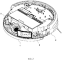
FIG. 2 is a schematic view of the installation of a down-pressure assembly of the utility model; -
FIG. 3 is a schematic view of the installation of the sweeper water tank of the utility model; -
FIG. 4 is a schematic view of a bottom structure of a sweeper body of the utility model; -
FIG. 5 is a schematic view of an overall structure of the down-pressure assembly of the utility model; -
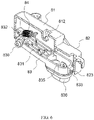
FIG. 6 is a schematic view of an internal structure of the down-pressure assembly of the utility model; -
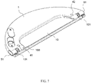
FIG. 7 is a schematic view of an overall structure of the sweeper water tank of the utility model; -
FIGS. 8 to 9 are schematic views of an internal structure of the sweeper water tank of the utility model; and -
FIG. 10 is a schematic view of the installation of a lock of the utility model. - In the drawings: 9: sweeper body; 90: mounting part; 900: protrusion portion; 1: sweeper water tank; 8: down-pressure assembly; 836: down-pressure protrusion; 82: lower shell; 81: upper shell; 812: first hook; 83: turning plate; 830: turning block; 832: second hook; 84: tension spring; 833: first turning limit block; 823: second turning limit block; 821: first lower shell fixing ear plate; 822: second lower shell fixing ear plate; 811: upper shell fixing ear plate; 10: recessed portion; 100: mounting slot; 901: mounting insert; 51: lock; 510: L-shaped positioning cavity; 511: lock positioning block; 513: lock positioning plate; 512: hook; 14: lock limiting plate; 15: return spring; 131: water tank installation groove; 91: first hook 92: second hook; 101: water storage cavity; 102: energized cavity; 61: filter device; 72: water outlet pipe; 60: water pump: 41: first energizing piece; 42: second energizing piece; 621: water inlet hose; 622: water outlet hose; 722: drain channel; 21: drain hole; 20: wheel cover; 22: walking wheel; 834: down-pressure charging piece; 835: conductive plate; 831: reinforcing rib; 810: inspection hole; 820: wire hole.
- The following describes the utility model in further detail with reference to the accompanying drawings, so that those skilled in the art can implement it with reference to the text of the description.
- As shown in
FIGS. 1 to 10 , the present utility model provides a down-pressure mopping type sweeping robot, including: - a
sweeper body 9 including a battery pack installed inside thesweeper body 9 and amounting portion 90 formed at a bottom of thesweeper body 9, aprotrusion portion 900 being formed in themounting portion 90; and - a
sweeper water tank 1 detachably installed in the mountingportion 90 for wetting a ground to be cleaned during a mopping process, a bottom of thesweeper water tank 1 being fixed with a rag through a sticky-and-hook strap; - As an embodiment of the present utility model, the down-
pressure assembly 8 includes: - a
lower shell 82 of which an upper side and a lower side are formed as open; - an
upper shell 81 fixed to a top of thelower shell 82 by a buckle, afirst hook 812 being formed inside theupper shell 81; - a turning
plate 83 having a hollow shell structure, one end of the turningplate 83 being hingedly mounted on a bottom of thelower shell 82 through aturning block 830, asecond hook 832 being formed at the one end of the turningplate 83; and - a
tension spring 84 of which one end is fixed to thesecond hook 832 and the other end is fixed on thefirst hook 812, in order to provide a flipping force for the other end of the turningplate 83 to move toward the bottom of thelower shell 82; - As an embodiment of the present utility model, a first lower shell fixing
ear plate 821 is formed at the one end of thelower shell 82, and a second lower shell fixingear plate 822 is formed at the other end of thelower shell 82; - an upper shell fixing
ear plate 811 is formed at one end of theupper shell 81; and - the bolt is capable of passing through the upper shell fixing
ear plate 811 and the first lower shell fixingear plate 821 in sequence in order to fix one end of the down-pressure assembly 8 in thesweeper body 9; and wherein the bolt is capable of passing through the second lower shell fixingear plate 822 in order to fix the other end of the down-pressure assembly 8 in thesweeper body 9. - As an embodiment of the present utility model, a recessed
portion 10 is formed on a top of thesweeper water tank 1, and mountingslots 100 are formed on both sides of the recessedportion 10; and
wherein mountinginserts 901 are formed on both sides of theprotrusion portion 900, and the mountinginserts 901 are capable of being inserted into the mountingslots 100 so that theprotrusion portion 900 is introduced and installed in the recessedportion 10. - As an embodiment of the present utility model, both sides of the
sweeper water tank 1 are formed with lock installation cavities, alock 51 is slidably installed in the lock installation cavity; - an L-shaped
positioning cavity 510 is formed on thelock 51, alock positioning block 511 is fixed at one end of an inner side of the L-shapedpositioning cavity 510, and alock positioning plate 513 is formed at the other end of the inner side of the L-shapedpositioning cavity 510; - a
hook 512 is also formed at the other end of the inner side of the L-shapedpositioning cavity 510; - a
lock limiting plate 14 is fixedly disposed in the lock installation cavity, areturn spring 15 is installed between thelock limiting plate 14 and thelock positioning block 511; - a front side of the
sweeper water tank 1 includes two watertank installation grooves 131 communicating with the two lock installation cavities, respectively; - a
first hook 91 and asecond hook 92 are formed in the mountingportion 90 which is located on both sides of theprotrusion portion 900, and thefirst hook 91 and thesecond hook 92 are capable of passing through the watertank installation grooves 131 and are correspondingly hooked to the two hooks 512. - As an embodiment of the present utility model, a
water storage cavity 101 and anenergized cavity 102 are sealedly formed in thesweeper water tank 1; - a
filter device 61 and awater outlet pipe 72 are fixedly disposed in thewater storage cavity 101, awater pump 60 and a first energizingpiece 41 and a second energizingpiece 42 for transmitting power to thewater pump 60 are fixedly disposed in the energizedcavity 102; - a
water inlet hose 621 and awater outlet hose 622 are installed on thewater pump 60, and thewater inlet hose 621 and thewater outlet hose 622 both extend into thewater storage cavity 101; - the
water inlet hose 621 and thefilter device 61 are in communication, and thewater outlet hose 622 and thewater outlet pipe 72 are in communication; and - a plurality of
drain channels 722 are opened at a bottom of thewater outlet pipe 72. - As an embodiment of the present utility model, the bottom of the
sweeper water tank 1 includes a plurality of drain holes 21 which are in sealed communication with the plurality ofdrain channels 722; and
the rag is disposed at a bottom of the plurality of drain holes 21. - As an embodiment of the present utility model, a bottom of the
sweeper water tank 1 is formed with awheel cover 20 recessed into thewater storage cavity 101. A bottom of thewheel cover 20 is provided with awalking wheel 22 for supporting the movement of thesweeper water tank 1 on a bottom surface of the work. - As an embodiment of the present utility model, the first energizing
piece 41 and the second energizingpiece 42 are both embedded and fixed in a top of thesweeper water tank 1; - a bottom of the down-
pressure protrusion 836 is fixed with a down-pressure charging piece 834, the two down-pressure charging pieces 834 are correspondingly energized and connected to the first energizingpiece 41 and the second energizingpiece 42; and - a
conductive plate 835 which is electrically connected to the down-pressure charging piece 834 is fixed inside the turningplate 83, and the twoconductive plates 835 are electrically connected to the battery pack. - As an embodiment of the present utility model, a plurality of reinforcing
ribs 831 are formed inside the turningplate 83. - As an embodiment of the present utility model, the
upper shell 81 located on top of thefirst hook 812 includes aninspection hole 810, and thelower shell 82 located on top of theconductive plate 835 includes awire hole 820. - The working principle of the down-pressure mopping type sweeping robot is as follows:
- The
sweeper body 9 pushes thesweeper water tank 1 to move on the bottom surface of the working through its walking mechanism. When it is necessary to wet the ground to be cleaned, the sweeping robot controls the operation of thewater pump 60. The water stored in thewater storage cavity 101 sequentially passes through thefilter device 61, thewater inlet hose 621, thewater pump 60, thewater outlet hose 622, thewater outlet pipe 72, and thedrain channel 722, and is finally led to the rag through the drain holes 21, and then moisten the floor with the rag with clean water. - In the process of mopping the floor with the rag, the down-
pressure protrusions 836 can continuously press thesweeper water tank 1, so that the rag can be stably pressed on the ground to be cleaned. The down-pressure charging pieces 834 fixed at the bottom of the two down-pressure protrusions 836 can be correspondingly energized and connected to the first energizingpiece 41 and the second energizingpiece 42, in order to realize the normal operation of thewater pump 60 driven by the power of the battery pack. - Although the embodiment of the present invention has been disclosed as above, it is not limited to the applications listed in the specification and the embodiments, and it can be applied to various fields suitable for the present utility model. For those skilled in the art, additional modifications can be easily implemented. Therefore, without departing from the general concept defined by the claims and equivalent scope, the present utility is not limited to the specific details and the drawings shown and described here.
Claims (10)
- A down-pressure mopping type sweeping robot, comprising:a sweeper body (9) comprising a battery pack installed inside the sweeper body (9) and a mounting portion (90) formed at a bottom of the sweeper body (9), a protrusion portion (900) being formed in the mounting portion (90); anda sweeper water tank (1) detachably installed in the mounting portion (90) for wetting a ground to be cleaned during a mopping process, a bottom of the sweeper water tank (1) being fixed with a rag through a sticky-and-hook strap;wherein both sides of an inside of the sweeper body (9) are fixed with down-pressure assemblies (8) by bolts; the down-pressure assembly (8) comprises a down-pressure protrusion (836) capable of elastically protruding into the mounting portion (90); and the down-pressure protrusion (836) is elastically pressed downwardly on a top of the sweeper water tank (1) so that the rag can be stably pressed against the ground to be cleaned.
- The down-pressure mopping type sweeping robot according to claim 1, wherein the down-pressure assembly (8) comprises:a lower shell (82) of which an upper side and a lower side are formed as open;an upper shell (81) fixed to a top of the lower shell (82) by a buckle, a first hook (812) being formed inside the upper shell (81);a turning plate (83) having a hollow shell structure, one end of the turning plate (83) being hingedly mounted on a bottom of the lower shell (82) through a turning block (830), a second hook (832) being formed at the one end of the turning plate (83); anda tension spring (84) of which one end is fixed to the second hook (832) and the other end is fixed on the first hook (812), in order to provide a flipping force for the other end of the turning plate (83) to move toward the bottom of the lower shell (82);wherein the down-pressure protrusions (836) are formed on a bottom side of the other end of the turning plate (83); a first turning limit block (833) is formed on the other end of the turning plate (83); and a second turning limit block (823) corresponding to a position of the first turning limit block (833) is formed on an inner side of the lower shell (82).
- The down-pressure mopping type sweeping robot according to claim 2, wherein a first lower shell fixing ear plate (821) is formed at the one end of the lower shell (82), and a second lower shell fixing ear plate (822) is formed at the other end of the lower shell (82);an upper shell fixing ear plate (811) is formed at one end of the upper shell (81); andthe bolt is capable of passing through the upper shell fixing ear plate (811) and the first lower shell fixing ear plate (821) in sequence in order to fix one end of the down-pressure assembly (8) in the sweeper body (9); and wherein the bolt is capable of passing through the second lower shell fixing ear plate (822) in order to fix the other end of the down-pressure assembly (8) in the sweeper body (9).
- The down-pressure mopping type sweeping robot according to claim 1, wherein a recessed portion (10) is formed on a top of the sweeper water tank (1), and mounting slots (100) are formed on both sides of the recessed portion (10); and
wherein mounting inserts (901) are formed on both sides of the protrusion portion (900), and the mounting inserts (901) are capable of being inserted into the mounting slots (100) so that the protrusion portion (900) is introduced and installed in the recessed portion (10). - The down-pressure mopping type sweeping robot according to claim 4, wherein both sides of the sweeper water tank (1) are formed with lock installation cavities, a lock (51) is slidably installed in the lock installation cavity;an L-shaped positioning cavity (510) is formed on the lock (51), a lock positioning block (511) is fixed at one end of an inner side of the L-shaped positioning cavity (510), and a lock positioning plate (513) is formed at the other end of the inner side of the L-shaped positioning cavity (510);a hook (512) is also formed at the other end of the inner side of the L-shaped positioning cavity (510);a lock limiting plate (14) is fixedly disposed in the lock installation cavity, a return spring (15) is installed between the lock limiting plate (14) and the lock positioning block (511);a front side of the sweeper water tank (1) comprises two water tank installation grooves (131) communicating with the two lock installation cavities, respectively;a first hook (91) and a second hook (92) are formed in the mounting portion (90) which is located on both sides of the protrusion portion (900), and the first hook (91) and the second hook (92) are capable of passing through the water tank installation grooves (131) and are correspondingly hooked to the two hooks (512).
- The down-pressure mopping type sweeping robot according to claim 2, wherein a water storage cavity (101) and an energized cavity (102) are sealedly formed in the sweeper water tank (1);a filter device (61) and a water outlet pipe (72) are fixedly disposed in the water storage cavity (101), a water pump (60) and a first energizing piece (41) and a second energizing piece (42) for transmitting power to the water pump (60) are fixedly disposed in the energized cavity (102);a water inlet hose (621) and a water outlet hose (622) are installed on the water pump (60), and the water inlet hose (621) and the water outlet hose (622) both extend into the water storage cavity (101);the water inlet hose (621) and the filter device (61) are in communication, and the water outlet hose (622) and the water outlet pipe (72) are in communication; anda plurality of drain channels (722) are opened at a bottom of the water outlet pipe (72).
- The down-pressure mopping type sweeping robot according to claim 6, wherein the bottom of the sweeper water tank (1) comprises a plurality of drain holes (21) which are in sealed communication with the plurality of drain channels (722); and
the rag is disposed at a bottom of the plurality of drain holes (21). - The down-pressure mopping type sweeping robot according to claim 6, wherein the first energizing piece (41) and the second energizing piece (42) are both embedded and fixed in a top of the sweeper water tank (1);a bottom of the down-pressure protrusion (836) is fixed with a down-pressure charging piece (834), the two down-pressure charging pieces (834) are correspondingly energized and connected to the first energizing piece (41) and the second energizing piece (42); anda conductive plate (835) which is electrically connected to the down-pressure charging piece (834) is fixed inside the turning plate (83), and the two conductive plates (835) are electrically connected to the battery pack.
- The down-pressure mopping type sweeping robot according to claim 2, wherein a plurality of reinforcing ribs (831) are formed inside the turning plate (83).
- The down-pressure mopping type sweeping robot according to claim 8, wherein the upper shell (81) located on top of the first hook (812) comprises an inspection hole (810), and the lower shell (82) located on top of the conductive plate (835) comprises a wire hole (820).
Applications Claiming Priority (2)
| Application Number | Priority Date | Filing Date | Title |
|---|---|---|---|
| CN201910753522.1A CN110353582B (en) | 2019-08-15 | 2019-08-15 | A kind of downward mopping type sweeping robot |
| PCT/CN2019/120428 WO2021027178A1 (en) | 2019-08-15 | 2019-11-22 | Press-down-mopping-type floor sweeping robot |
Publications (2)
| Publication Number | Publication Date |
|---|---|
| EP4014828A1 true EP4014828A1 (en) | 2022-06-22 |
| EP4014828A4 EP4014828A4 (en) | 2022-10-05 |
Family
ID=68223916
Family Applications (1)
| Application Number | Title | Priority Date | Filing Date |
|---|---|---|---|
| EP19941313.9A Withdrawn EP4014828A4 (en) | 2019-08-15 | 2019-11-22 | DOWN PRESSURE CLEANING TYPE FLOOR SWEEPING ROBOT |
Country Status (8)
| Country | Link |
|---|---|
| US (1) | US20220202268A1 (en) |
| EP (1) | EP4014828A4 (en) |
| JP (1) | JP7291849B2 (en) |
| KR (1) | KR20220047565A (en) |
| CN (1) | CN110353582B (en) |
| AU (1) | AU2019461015A1 (en) |
| CA (1) | CA3145808A1 (en) |
| WO (1) | WO2021027178A1 (en) |
Families Citing this family (16)
| Publication number | Priority date | Publication date | Assignee | Title |
|---|---|---|---|---|
| CN110353582B (en) * | 2019-08-15 | 2023-10-27 | 追觅创新科技(苏州)有限公司 | A kind of downward mopping type sweeping robot |
| CN112773263B (en) * | 2019-11-10 | 2024-06-14 | 佛山市云米电器科技有限公司 | Sweeping robot |
| CN113558537A (en) * | 2020-04-28 | 2021-10-29 | 深圳赤马人工智能有限公司 | Mop assembly of cleaning robot |
| CN111449580A (en) * | 2020-05-22 | 2020-07-28 | 深圳市伽利略机器人有限公司 | Floor mopping robot capable of controlling continuous water outlet |
| CA207582S (en) * | 2021-01-04 | 2022-08-16 | Beijing Roborock Technology Co Ltd | Sweeping robot |
| JP1747939S (en) * | 2021-02-10 | 2023-07-04 | Support plate for cleaning pad for robot vacuum cleaner | |
| CA207549S (en) * | 2021-03-05 | 2023-02-27 | Beijing Roborock Technology Co Ltd | Robotic vacuum cleaner |
| USD990080S1 (en) * | 2021-03-11 | 2023-06-20 | Beijing Xiaomi Mobile Software Co., Ltd. | Intelligent sweeping robot |
| USD1019029S1 (en) * | 2021-05-17 | 2024-03-19 | Bissell Inc. | Autonomous floor cleaner |
| USD990802S1 (en) * | 2021-08-05 | 2023-06-27 | Shenzhen Haitao Optimization Technology Co., Ltd. | Sweeping robot |
| USD1017155S1 (en) * | 2022-04-02 | 2024-03-05 | Dongguan Pinjia Intelligent Technology Co., Ltd | Robot vacuum cleaner |
| CN115500734B (en) * | 2022-09-23 | 2024-01-30 | 深圳市八达威科技有限公司 | Floor sweeping machine with split laser radar |
| JP1792768S (en) * | 2024-02-05 | 2025-03-05 | Cleaning robot | |
| USD1080108S1 (en) * | 2024-02-05 | 2025-06-17 | Beijing Roborock Technology Co., Ltd. | Cleaning robot with sweeping and mopping parts |
| USD1123278S1 (en) * | 2024-07-15 | 2026-04-21 | Beijing Roborock Technology Co., Ltd. | Cleaning robot |
| USD1111280S1 (en) * | 2024-09-24 | 2026-02-03 | Guangdong Dadier intelligent robot Co., LTD | Robot vacuum cleaner |
Family Cites Families (21)
| Publication number | Priority date | Publication date | Assignee | Title |
|---|---|---|---|---|
| AU2001281276A1 (en) * | 2000-05-02 | 2001-11-12 | Personal Robotics, Inc. | Autonomous floor mopping apparatus |
| KR20120088314A (en) * | 2011-01-31 | 2012-08-08 | 엘지전자 주식회사 | A robot cleaner comprising a mop mounting plate which is able to reciprocate |
| KR20120129192A (en) * | 2011-05-19 | 2012-11-28 | 어수곤 | robot cleaner |
| US8898844B1 (en) * | 2011-07-08 | 2014-12-02 | Irobot Corporation | Mopping assembly for a mobile robot |
| CN105796015A (en) * | 2014-12-31 | 2016-07-27 | 科沃斯机器人有限公司 | Self-moving ground treating device |
| CN205181229U (en) * | 2015-11-27 | 2016-04-27 | 鲜军 | Ground all -in -one is dragged in multi -functional dust absorption box and dust absorption that has this suction box body |
| CN105662280B (en) * | 2016-02-14 | 2019-03-19 | 福玛特机器人科技股份有限公司 | cleaning robot |
| CN206285061U (en) * | 2016-08-23 | 2017-06-30 | 宁波克林斯曼智能科技有限公司 | A kind of sweeping robot water tank erecting device |
| CN206355004U (en) * | 2016-10-12 | 2017-07-28 | 深圳市智意科技有限公司 | Embed floating type radiator assembling structure and intelligent sweeping |
| CN208598297U (en) | 2017-01-26 | 2019-03-15 | 深圳洛克时代科技有限公司 | Intelligent cleaning equipment |
| CN207545024U (en) * | 2017-03-18 | 2018-06-29 | 李伟光 | A kind of concrete finishing trowel structure of sweeper |
| CN207429065U (en) * | 2017-03-28 | 2018-06-01 | 深圳市智意科技有限公司 | Automatic ground cleaning |
| CN207253312U (en) * | 2017-04-13 | 2018-04-20 | 广州迪腾电子科技有限公司 | A kind of New Sweeping Floor Machine water tank |
| CN208228914U (en) * | 2017-07-31 | 2018-12-14 | 广东美的厨房电器制造有限公司 | Hold-down mechanism and mopping device |
| US10736479B2 (en) * | 2017-12-27 | 2020-08-11 | Jiangsu Midea Cleaning Appliances Co., Ltd. | Drive-wheel suspension mechanism for smart movable device and smart movable device |
| CN108372508B (en) * | 2018-02-26 | 2021-03-19 | 浙江际沃智能科技有限公司 | An intelligent sweeping suction and dragging robot with cleaning device |
| CN208808370U (en) * | 2018-04-23 | 2019-05-03 | 江苏美的清洁电器股份有限公司 | Cistern assembly and sweeping robot for sweeping robot |
| CN109730588B (en) * | 2019-01-31 | 2024-04-09 | 深圳和而泰智能控制股份有限公司 | Floor wiping robot |
| US11771290B2 (en) * | 2019-05-20 | 2023-10-03 | Irobot Corporation | Sensors for an autonomous cleaning robot |
| CN110353582B (en) * | 2019-08-15 | 2023-10-27 | 追觅创新科技(苏州)有限公司 | A kind of downward mopping type sweeping robot |
| CN210871346U (en) * | 2019-08-15 | 2020-06-30 | 追创科技(苏州)有限公司 | Down-pressing floor-mopping type floor sweeping robot |
-
2019
- 2019-08-15 CN CN201910753522.1A patent/CN110353582B/en active Active
- 2019-11-22 CA CA3145808A patent/CA3145808A1/en active Pending
- 2019-11-22 JP JP2022506286A patent/JP7291849B2/en active Active
- 2019-11-22 EP EP19941313.9A patent/EP4014828A4/en not_active Withdrawn
- 2019-11-22 KR KR1020227001592A patent/KR20220047565A/en not_active Ceased
- 2019-11-22 US US17/607,394 patent/US20220202268A1/en not_active Abandoned
- 2019-11-22 AU AU2019461015A patent/AU2019461015A1/en not_active Abandoned
- 2019-11-22 WO PCT/CN2019/120428 patent/WO2021027178A1/en not_active Ceased
Also Published As
| Publication number | Publication date |
|---|---|
| CN110353582B (en) | 2023-10-27 |
| CN110353582A (en) | 2019-10-22 |
| EP4014828A4 (en) | 2022-10-05 |
| US20220202268A1 (en) | 2022-06-30 |
| CA3145808A1 (en) | 2021-02-18 |
| AU2019461015A1 (en) | 2022-02-24 |
| KR20220047565A (en) | 2022-04-18 |
| WO2021027178A1 (en) | 2021-02-18 |
| JP2022542423A (en) | 2022-10-03 |
| JP7291849B2 (en) | 2023-06-15 |
Similar Documents
| Publication | Publication Date | Title |
|---|---|---|
| US20220202268A1 (en) | Down-pressure mopping type sweeping robot | |
| CN206151378U (en) | Cleaning machine | |
| US20210393098A1 (en) | Maintenance station for cleaning robot | |
| WO2022213446A1 (en) | Base station and cleaning robot system | |
| US8955531B2 (en) | High pressure water cleaner with detachable water tank | |
| CN113951768A (en) | Cleaning equipment base station and cleaning equipment system | |
| CN112773263B (en) | Sweeping robot | |
| CN111297274A (en) | Floor wiping machine | |
| CN202154650U (en) | Multifunctional mop | |
| CN210842882U (en) | Sweeper water tank integrated with water spraying part | |
| CN217479790U (en) | Clothes treatment equipment and cleaning system | |
| RU2789863C1 (en) | Washing type pressure robot vacuum cleaner | |
| CN213282727U (en) | Garbage recovery system | |
| CN210871346U (en) | Down-pressing floor-mopping type floor sweeping robot | |
| CN219846362U (en) | Surface cleaning device | |
| CN215457665U (en) | Floor sweeping robot | |
| CN113413104B (en) | Charging device for steam mop | |
| CN114086366A (en) | Detergent box and clothes treatment equipment | |
| CN114059305A (en) | Detergent box and clothes treatment equipment | |
| CN216439151U (en) | A surface cleaning device with reliable structure | |
| CN215738744U (en) | Wipe assemblies, cleaning units and cleaning equipment | |
| CN222091598U (en) | Quick-release structure of floor washing machine | |
| CN216628465U (en) | Mop bucket subassembly and mop cleaning device | |
| CN221153980U (en) | Liquid storage tank and cleaning robot | |
| CN209847122U (en) | Cleaning device |
Legal Events
| Date | Code | Title | Description |
|---|---|---|---|
| STAA | Information on the status of an ep patent application or granted ep patent |
Free format text: STATUS: THE INTERNATIONAL PUBLICATION HAS BEEN MADE |
|
| PUAI | Public reference made under article 153(3) epc to a published international application that has entered the european phase |
Free format text: ORIGINAL CODE: 0009012 |
|
| STAA | Information on the status of an ep patent application or granted ep patent |
Free format text: STATUS: REQUEST FOR EXAMINATION WAS MADE |
|
| 17P | Request for examination filed |
Effective date: 20220121 |
|
| AK | Designated contracting states |
Kind code of ref document: A1 Designated state(s): AL AT BE BG CH CY CZ DE DK EE ES FI FR GB GR HR HU IE IS IT LI LT LU LV MC MK MT NL NO PL PT RO RS SE SI SK SM TR |
|
| A4 | Supplementary search report drawn up and despatched |
Effective date: 20220905 |
|
| RIC1 | Information provided on ipc code assigned before grant |
Ipc: A47L 11/40 20060101AFI20220830BHEP |
|
| DAV | Request for validation of the european patent (deleted) | ||
| DAX | Request for extension of the european patent (deleted) | ||
| STAA | Information on the status of an ep patent application or granted ep patent |
Free format text: STATUS: THE APPLICATION IS DEEMED TO BE WITHDRAWN |
|
| 18D | Application deemed to be withdrawn |
Effective date: 20240601 |