EP4014097B1 - Vorrichtung und verfahren zur reparatur von bauteilen mittels additiver fertigung - Google Patents
Vorrichtung und verfahren zur reparatur von bauteilen mittels additiver fertigung Download PDFInfo
- Publication number
- EP4014097B1 EP4014097B1 EP20753299.5A EP20753299A EP4014097B1 EP 4014097 B1 EP4014097 B1 EP 4014097B1 EP 20753299 A EP20753299 A EP 20753299A EP 4014097 B1 EP4014097 B1 EP 4014097B1
- Authority
- EP
- European Patent Office
- Prior art keywords
- path
- tool
- threshold value
- pfp
- filling cycle
- Prior art date
- Legal status (The legal status is an assumption and is not a legal conclusion. Google has not performed a legal analysis and makes no representation as to the accuracy of the status listed.)
- Active
Links
Images




Classifications
-
- B—PERFORMING OPERATIONS; TRANSPORTING
- B22—CASTING; POWDER METALLURGY
- B22F—WORKING METALLIC POWDER; MANUFACTURE OF ARTICLES FROM METALLIC POWDER; MAKING METALLIC POWDER; APPARATUS OR DEVICES SPECIALLY ADAPTED FOR METALLIC POWDER
- B22F10/00—Additive manufacturing of workpieces or articles from metallic powder
- B22F10/20—Direct sintering or melting
-
- G—PHYSICS
- G06—COMPUTING OR CALCULATING; COUNTING
- G06F—ELECTRIC DIGITAL DATA PROCESSING
- G06F30/00—Computer-aided design [CAD]
- G06F30/20—Design optimisation, verification or simulation
-
- B—PERFORMING OPERATIONS; TRANSPORTING
- B22—CASTING; POWDER METALLURGY
- B22F—WORKING METALLIC POWDER; MANUFACTURE OF ARTICLES FROM METALLIC POWDER; MAKING METALLIC POWDER; APPARATUS OR DEVICES SPECIALLY ADAPTED FOR METALLIC POWDER
- B22F10/00—Additive manufacturing of workpieces or articles from metallic powder
- B22F10/20—Direct sintering or melting
- B22F10/25—Direct deposition of metal particles, e.g. direct metal deposition [DMD] or laser engineered net shaping [LENS]
-
- B—PERFORMING OPERATIONS; TRANSPORTING
- B22—CASTING; POWDER METALLURGY
- B22F—WORKING METALLIC POWDER; MANUFACTURE OF ARTICLES FROM METALLIC POWDER; MAKING METALLIC POWDER; APPARATUS OR DEVICES SPECIALLY ADAPTED FOR METALLIC POWDER
- B22F10/00—Additive manufacturing of workpieces or articles from metallic powder
- B22F10/20—Direct sintering or melting
- B22F10/28—Powder bed fusion, e.g. selective laser melting [SLM] or electron beam melting [EBM]
-
- B—PERFORMING OPERATIONS; TRANSPORTING
- B22—CASTING; POWDER METALLURGY
- B22F—WORKING METALLIC POWDER; MANUFACTURE OF ARTICLES FROM METALLIC POWDER; MAKING METALLIC POWDER; APPARATUS OR DEVICES SPECIALLY ADAPTED FOR METALLIC POWDER
- B22F10/00—Additive manufacturing of workpieces or articles from metallic powder
- B22F10/30—Process control
- B22F10/36—Process control of energy beam parameters
- B22F10/366—Scanning parameters, e.g. hatch distance or scanning strategy
-
- B—PERFORMING OPERATIONS; TRANSPORTING
- B22—CASTING; POWDER METALLURGY
- B22F—WORKING METALLIC POWDER; MANUFACTURE OF ARTICLES FROM METALLIC POWDER; MAKING METALLIC POWDER; APPARATUS OR DEVICES SPECIALLY ADAPTED FOR METALLIC POWDER
- B22F10/00—Additive manufacturing of workpieces or articles from metallic powder
- B22F10/80—Data acquisition or data processing
- B22F10/85—Data acquisition or data processing for controlling or regulating additive manufacturing processes
-
- B—PERFORMING OPERATIONS; TRANSPORTING
- B23—MACHINE TOOLS; METAL-WORKING NOT OTHERWISE PROVIDED FOR
- B23K—SOLDERING OR UNSOLDERING; WELDING; CLADDING OR PLATING BY SOLDERING OR WELDING; CUTTING BY APPLYING HEAT LOCALLY, e.g. FLAME CUTTING; WORKING BY LASER BEAM
- B23K26/00—Working by laser beam, e.g. welding, cutting or boring
- B23K26/02—Positioning or observing the workpiece, e.g. with respect to the point of impact; Aligning, aiming or focusing the laser beam
- B23K26/03—Observing, e.g. monitoring, the workpiece
- B23K26/032—Observing, e.g. monitoring, the workpiece using optical means
-
- B—PERFORMING OPERATIONS; TRANSPORTING
- B23—MACHINE TOOLS; METAL-WORKING NOT OTHERWISE PROVIDED FOR
- B23K—SOLDERING OR UNSOLDERING; WELDING; CLADDING OR PLATING BY SOLDERING OR WELDING; CUTTING BY APPLYING HEAT LOCALLY, e.g. FLAME CUTTING; WORKING BY LASER BEAM
- B23K26/00—Working by laser beam, e.g. welding, cutting or boring
- B23K26/14—Working by laser beam, e.g. welding, cutting or boring using a fluid stream, e.g. a jet of gas, in conjunction with the laser beam; Nozzles therefor
- B23K26/144—Working by laser beam, e.g. welding, cutting or boring using a fluid stream, e.g. a jet of gas, in conjunction with the laser beam; Nozzles therefor the fluid stream containing particles, e.g. powder
-
- B—PERFORMING OPERATIONS; TRANSPORTING
- B23—MACHINE TOOLS; METAL-WORKING NOT OTHERWISE PROVIDED FOR
- B23K—SOLDERING OR UNSOLDERING; WELDING; CLADDING OR PLATING BY SOLDERING OR WELDING; CUTTING BY APPLYING HEAT LOCALLY, e.g. FLAME CUTTING; WORKING BY LASER BEAM
- B23K26/00—Working by laser beam, e.g. welding, cutting or boring
- B23K26/34—Laser welding for purposes other than joining
- B23K26/342—Build-up welding
-
- B—PERFORMING OPERATIONS; TRANSPORTING
- B23—MACHINE TOOLS; METAL-WORKING NOT OTHERWISE PROVIDED FOR
- B23P—METAL-WORKING NOT OTHERWISE PROVIDED FOR; COMBINED OPERATIONS; UNIVERSAL MACHINE TOOLS
- B23P6/00—Restoring or reconditioning objects
-
- B—PERFORMING OPERATIONS; TRANSPORTING
- B33—ADDITIVE MANUFACTURING TECHNOLOGY
- B33Y—ADDITIVE MANUFACTURING, i.e. MANUFACTURING OF THREE-DIMENSIONAL [3D] OBJECTS BY ADDITIVE DEPOSITION, ADDITIVE AGGLOMERATION OR ADDITIVE LAYERING, e.g. BY 3D PRINTING, STEREOLITHOGRAPHY OR SELECTIVE LASER SINTERING
- B33Y10/00—Processes of additive manufacturing
-
- B—PERFORMING OPERATIONS; TRANSPORTING
- B33—ADDITIVE MANUFACTURING TECHNOLOGY
- B33Y—ADDITIVE MANUFACTURING, i.e. MANUFACTURING OF THREE-DIMENSIONAL [3D] OBJECTS BY ADDITIVE DEPOSITION, ADDITIVE AGGLOMERATION OR ADDITIVE LAYERING, e.g. BY 3D PRINTING, STEREOLITHOGRAPHY OR SELECTIVE LASER SINTERING
- B33Y30/00—Apparatus for additive manufacturing; Details thereof or accessories therefor
-
- B—PERFORMING OPERATIONS; TRANSPORTING
- B33—ADDITIVE MANUFACTURING TECHNOLOGY
- B33Y—ADDITIVE MANUFACTURING, i.e. MANUFACTURING OF THREE-DIMENSIONAL [3D] OBJECTS BY ADDITIVE DEPOSITION, ADDITIVE AGGLOMERATION OR ADDITIVE LAYERING, e.g. BY 3D PRINTING, STEREOLITHOGRAPHY OR SELECTIVE LASER SINTERING
- B33Y50/00—Data acquisition or data processing for additive manufacturing
- B33Y50/02—Data acquisition or data processing for additive manufacturing for controlling or regulating additive manufacturing processes
-
- B—PERFORMING OPERATIONS; TRANSPORTING
- B33—ADDITIVE MANUFACTURING TECHNOLOGY
- B33Y—ADDITIVE MANUFACTURING, i.e. MANUFACTURING OF THREE-DIMENSIONAL [3D] OBJECTS BY ADDITIVE DEPOSITION, ADDITIVE AGGLOMERATION OR ADDITIVE LAYERING, e.g. BY 3D PRINTING, STEREOLITHOGRAPHY OR SELECTIVE LASER SINTERING
- B33Y99/00—Subject matter not provided for in other groups of this subclass
-
- G—PHYSICS
- G05—CONTROLLING; REGULATING
- G05B—CONTROL OR REGULATING SYSTEMS IN GENERAL; FUNCTIONAL ELEMENTS OF SUCH SYSTEMS; MONITORING OR TESTING ARRANGEMENTS FOR SUCH SYSTEMS OR ELEMENTS
- G05B19/00—Program-control systems
- G05B19/02—Program-control systems electric
- G05B19/18—Numerical control [NC], i.e. automatically operating machines, in particular machine tools, e.g. in a manufacturing environment, so as to execute positioning, movement or co-ordinated operations by means of program data in numerical form
- G05B19/19—Numerical control [NC], i.e. automatically operating machines, in particular machine tools, e.g. in a manufacturing environment, so as to execute positioning, movement or co-ordinated operations by means of program data in numerical form characterised by positioning or contouring control systems, e.g. to control position from one programmed point to another or to control movement along a programmed continuous path
- G05B19/21—Numerical control [NC], i.e. automatically operating machines, in particular machine tools, e.g. in a manufacturing environment, so as to execute positioning, movement or co-ordinated operations by means of program data in numerical form characterised by positioning or contouring control systems, e.g. to control position from one programmed point to another or to control movement along a programmed continuous path using an incremental digital measuring device
- G05B19/23—Numerical control [NC], i.e. automatically operating machines, in particular machine tools, e.g. in a manufacturing environment, so as to execute positioning, movement or co-ordinated operations by means of program data in numerical form characterised by positioning or contouring control systems, e.g. to control position from one programmed point to another or to control movement along a programmed continuous path using an incremental digital measuring device for point-to-point control
-
- G—PHYSICS
- G05—CONTROLLING; REGULATING
- G05B—CONTROL OR REGULATING SYSTEMS IN GENERAL; FUNCTIONAL ELEMENTS OF SUCH SYSTEMS; MONITORING OR TESTING ARRANGEMENTS FOR SUCH SYSTEMS OR ELEMENTS
- G05B19/00—Program-control systems
- G05B19/02—Program-control systems electric
- G05B19/18—Numerical control [NC], i.e. automatically operating machines, in particular machine tools, e.g. in a manufacturing environment, so as to execute positioning, movement or co-ordinated operations by means of program data in numerical form
- G05B19/4097—Numerical control [NC], i.e. automatically operating machines, in particular machine tools, e.g. in a manufacturing environment, so as to execute positioning, movement or co-ordinated operations by means of program data in numerical form characterised by using design data to control NC machines, e.g. CAD/CAM
- G05B19/4099—Surface or curve machining, making three-dimensional [3D] objects, e.g. desktop manufacturing
-
- G—PHYSICS
- G05—CONTROLLING; REGULATING
- G05B—CONTROL OR REGULATING SYSTEMS IN GENERAL; FUNCTIONAL ELEMENTS OF SUCH SYSTEMS; MONITORING OR TESTING ARRANGEMENTS FOR SUCH SYSTEMS OR ELEMENTS
- G05B19/00—Program-control systems
- G05B19/02—Program-control systems electric
- G05B19/42—Recording and playback systems, i.e. in which the program is recorded from a cycle of operations, e.g. the cycle of operations being manually controlled, after which this record is played back on the same machine
- G05B19/4202—Recording and playback systems, i.e. in which the program is recorded from a cycle of operations, e.g. the cycle of operations being manually controlled, after which this record is played back on the same machine preparation of the program medium using a drawing, a model
- G05B19/4207—Recording and playback systems, i.e. in which the program is recorded from a cycle of operations, e.g. the cycle of operations being manually controlled, after which this record is played back on the same machine preparation of the program medium using a drawing, a model in which a model is traced or scanned and corresponding data recorded
-
- B—PERFORMING OPERATIONS; TRANSPORTING
- B22—CASTING; POWDER METALLURGY
- B22F—WORKING METALLIC POWDER; MANUFACTURE OF ARTICLES FROM METALLIC POWDER; MAKING METALLIC POWDER; APPARATUS OR DEVICES SPECIALLY ADAPTED FOR METALLIC POWDER
- B22F7/00—Manufacture of composite layers, workpieces, or articles, comprising metallic powder, by sintering the powder, with or without compacting wherein at least one part is obtained by sintering or compression
- B22F7/06—Manufacture of composite layers, workpieces, or articles, comprising metallic powder, by sintering the powder, with or without compacting wherein at least one part is obtained by sintering or compression of composite workpieces or articles from parts, e.g. to form tipped tools
- B22F7/062—Manufacture of composite layers, workpieces, or articles, comprising metallic powder, by sintering the powder, with or without compacting wherein at least one part is obtained by sintering or compression of composite workpieces or articles from parts, e.g. to form tipped tools involving the connection or repairing of preformed parts
- B22F2007/068—Manufacture of composite layers, workpieces, or articles, comprising metallic powder, by sintering the powder, with or without compacting wherein at least one part is obtained by sintering or compression of composite workpieces or articles from parts, e.g. to form tipped tools involving the connection or repairing of preformed parts repairing articles
-
- B—PERFORMING OPERATIONS; TRANSPORTING
- B22—CASTING; POWDER METALLURGY
- B22F—WORKING METALLIC POWDER; MANUFACTURE OF ARTICLES FROM METALLIC POWDER; MAKING METALLIC POWDER; APPARATUS OR DEVICES SPECIALLY ADAPTED FOR METALLIC POWDER
- B22F2999/00—Aspects linked to processes or compositions used in powder metallurgy
-
- Y—GENERAL TAGGING OF NEW TECHNOLOGICAL DEVELOPMENTS; GENERAL TAGGING OF CROSS-SECTIONAL TECHNOLOGIES SPANNING OVER SEVERAL SECTIONS OF THE IPC; TECHNICAL SUBJECTS COVERED BY FORMER USPC CROSS-REFERENCE ART COLLECTIONS [XRACs] AND DIGESTS
- Y02—TECHNOLOGIES OR APPLICATIONS FOR MITIGATION OR ADAPTATION AGAINST CLIMATE CHANGE
- Y02P—CLIMATE CHANGE MITIGATION TECHNOLOGIES IN THE PRODUCTION OR PROCESSING OF GOODS
- Y02P10/00—Technologies related to metal processing
- Y02P10/25—Process efficiency
Definitions
- the present invention relates to a device and a method for repairing components by means of additive manufacturing and in particular for repairing depressions in components.
- the first step is usually to mill out the repair area.
- the milled area is scanned, and a corresponding computer model is created. Based on this data, a structural model is then created, which can be inserted into the milled area to repair the damaged area.
- This type of repair process makes it possible to repair a damaged area on the surface of a component, allowing the original surface to be restored.
- the structure to be inserted can be produced using additive manufacturing processes and incorporated into the milled area.
- a repair procedure is, for example, from the US 2017/0370221 A1 known.
- the first step is to remove the defect from a component to be repaired.
- a repaired component can be created so that the component can once again retain its original geometry.
- known processes have the disadvantage that multiple data conversion and processing steps of the measurement data are necessary to create a structure from the measurement data of the component to be repaired, which can then be produced using the additive manufacturing process. This usually requires data processing. This results in a high computing effort and a high data expenditure.
- CN 108 340 582 A An automated repair process is described which, by taking thermal infrared images, can identify any defects within the component to be repaired and then adapt the repair process to the identified defects.
- the CN 109 676 135 A A processing process based on previous imaging is presented, in which a feedback repair system is generated using grayscale image analysis. More specifically, the aforementioned method initially detects existing defects within the component under investigation by comparing recorded image intensity data with predefined threshold values. In a subsequent process, the generated information is also passed on to an evaluation unit to enable a repair process specifically tailored to the defect.
- the task of The present invention aims to solve the problems described.
- it is an object to provide an efficient method for repairing components using additive manufacturing, as well as a corresponding device.
- a method for the automated repair of components using an additive manufacturing system can comprise a first step in which the defective component is clamped into the manufacturing system.
- a repair area can be defined that encompasses the surface of the component to be repaired.
- a tool path can be defined within the repair area. The tool path corresponds to the travel path that the tool of the manufacturing system travels in one cycle.
- the determined deviation can be the depth (or the amount thereof) of the damaged area at a point (measuring point).
- a selective application of filler or filling material can be carried out.
- the filler can be applied along the defined tool path in at least one filling cycle.
- part or preferably the entire tool path can be traversed, and the manufacturing system can be selectively activated to apply the filler depending on the difference between the data value along the path and a predetermined threshold value.
- This advantageous method makes it possible to use the data resulting directly from the measuring cycle as direct input for the filling cycle.
- the measuring cycle thus creates a data array with measured values for various path points (measurement points). This data array, in turn, serves as the input for the filling cycle and, after comparison with a predetermined threshold, determines whether the manufacturing system is activated or deactivated for applying the filler.
- the manufacturing system follows the defined tool path along the path points during the fill cycle. For each of the path points, a data value can be determined, which is then compared with the threshold value. When a path point is reached, the tool head, e.g., a laser, of the additive manufacturing system is activated and a material can be applied. When the next path point is reached, a comparison is performed to determine whether the tool head is deactivated or whether it remains activated.
- the measuring cycle and the filling cycle can be carried out automatically, enabling essentially automatic repair of the component.
- Complex and error-prone data conversions of point clouds of measured values which can result from measuring the damaged area of the component, are no longer necessary. This particularly advantageously results in a simplified process for repairing components using additive manufacturing, which also exhibits a lower susceptibility to failure.
- the tool path can have a plurality of path points.
- a deviation in a tool direction e.g., a Z direction
- the tool direction can, for example, be the direction orthogonal to the component surface in the repair area.
- the data values can indicate the deviation of the component surface in the tool direction, and the tool direction can be orthogonal to the workpiece surface (e.g., an XY plane) on which the tool path lies.
- the tool of the additive manufacturing system such as a laser, is thus moved along the workpiece surface along the tool path.
- This tool path or the workpiece surface can, for example, be orthogonal to the tool direction, which determines the deviation.
- the filler can be selectively applied along a path segment of the defined tool path.
- the filler can thus be applied during the process from one path point to the adjacent path point.
- Switching off the tool of the manufacturing system for applying the filler is determined at the target path point depending on the difference between the data value at the target path point and the predetermined threshold value. If, for example, the tool moves along the tool path from one path point to the next and the threshold value is always exceeded, the laser can be constantly activated so that the filler is always applied. Powder jet deposition welding, for example, can be provided as additive manufacturing. If a path point is reached during the process at which the data value is lower than the threshold value, the laser or tool head can be switched off. The laser is only activated again when another path point is reached at which the associated data value again exceeds the threshold value.
- a path segment can be defined by two path points, and the path segment can preferably be straight.
- This particularly efficient and simple configuration of the path segments, which together form the tool path, can further simplify the repair process, since curved segments are avoided and only one movement in one X-direction and one Y-direction is necessary.
- the data values can also be averaged values of path points of a segment. Activating the tool can therefore also be carried out segment by segment.
- the threshold value can be constant within a filling cycle.
- the manufacturing system's tool can thus traverse the entire repair area along the defined tool path, with each data point being compared with the threshold value of the filling cycle.
- a further filling cycle can be scheduled with a modified threshold value.
- This configuration of the filling cycles makes it possible to successively repair the defects.
- a plane is defined that is orthogonal to the tool direction.
- Each of these planes has a different threshold value until a minimum threshold value is reached at the last plane, so that a final surface (e.g., a flat surface) of the component in the repair area can be achieved. It is particularly advantageous to apply an additional allowance after the minimum threshold value has been reached. For example, after the minimum threshold value has been reached, the entire repair area can be filled with filler in one (or more) additional filling cycles.
- the threshold can be adjusted by one thickness value each time until a substantially uniform surface is achieved in the repair area.
- the original surface shape (e.g., linear or curved) of the component can thus be restored in the repair area.
- the thickness value can, for example, depend on the thickness of the material applied during the filling cycle.
- the result of the measurement cycle can be an array of the determined data values.
- the threshold value can be set for the first filling cycle based on a maximum value or a minimum value (extreme value) of the array and a constant. In particular, the maximum value of the array is used to determine the deepest defect in the repair area. Depending on this deepest point, the threshold value can be set so that in the The first filling cycle only fills the deepest damage areas. In the subsequent filling cycle, a reduced threshold is used so that additional areas can be filled with filler material. By successively following the filling cycles, the damaged areas are completely filled.
- the threshold value can be reduced by a thickness value in a subsequent filling cycle, wherein the thickness value corresponds to the height of the applied filler in a filling cycle, in particular at a path point or path segment.
- a height is, for example, the height of the weld seam.
- the data values determined during the measurement cycle can be used directly for the filling cycle. This eliminates the need for conversion, transformation, or digitization of the measurement cycle results. This provides a particularly efficient and simple repair procedure. Furthermore, the frequency of errors that can often arise due to conversion errors is avoided.
- Data values can be used (without data conversion) for comparison with the threshold value in the fill cycle.
- the unconverted data values from the measurement cycle are used directly to decide whether the adaptive manufacturing system tool is activated or deactivated (i.e., whether material is added) based on comparison with the threshold value at the respective path points.
- the method can thus advantageously be a method for creating a flat and/or curved surface in a repair area.
- the repaired surface shape advantageously corresponds to the original surface shape of the component.
- the tool path can advantageously be defined taking into account the working diameter of the manufacturing system.
- the working diameter of the adaptive manufacturing system can, for example, be the diameter of the laser (in powder jet deposition welding). Taking this working diameter into account, the tool path can be advantageously defined in such a way that the entire repair area can be completely covered.
- the tool path can be a non-overlapping, continuous line. More preferably, the tool path can be configured in a meandering shape. The tool path can also consist of line segments, each of which runs in a straight line. Thus, a particularly error-free process can be provided with an optimized tool path. Furthermore, the tool path can be configured to be contour-parallel to the repair area.
- the repair area can be defined so that the entire surface of the component to be repaired can be completely covered. This allows the process to create a flat surface (or, advantageously, a curved surface based on the original component shape) at the repair site.
- the additive manufacturing system's tool can be advantageously activated continuously while traversing the defined tool path. This approach makes it possible to compensate for any remaining unevenness. Furthermore, it can provide a stock allowance across the entire surface of the repair area.
- the defined tool path advantageously represents the process path of the additive manufacturing system's tool and, at the same time, the process path of the measuring instrument for determining the deviation. Converting the process path or tool path is therefore not necessary between the measuring cycle and the filling cycle, or between all filling cycles. This further reduces the computational effort and minimizes the risk of errors.
- the tool of the additive manufacturing system can be moved along the defined tool path from one path point to an adjacent path point.
- a comparison of the determined data value of the respective path point can be performed with a threshold value. If the threshold value is exceeded, the tool can be activated. If the threshold value is exceeded, the tool can be deactivated (or vice versa, with the opposite sign).
- the measuring cycle and the subsequent filling cycle are performed automatically, thus eliminating the need for manual intervention.
- Another advantage is that the measuring cycle and all subsequent filling cycles are performed automatically. The data values are thus the same for all filling cycles.
- an additional measuring cycle can be advantageously scheduled after each filling cycle for improved accuracy.
- the method may be a method for filling depressions of a component surface in a damaged area.
- the method can advantageously comprise the step of moving the tool along path points of the defined tool path, wherein upon reaching a path point at which the data value is greater than the threshold value, a laser is activated and upon reaching a path point at which the data value is not greater than the threshold value, the laser is deactivated.
- a plurality of filling cycles can be provided, wherein the threshold value can be reduced from filling cycle to filling cycle.
- the threshold value for the final filling cycle is reduced such that all data values of any data point are greater than the threshold value.
- the threshold value can be set such that several layers of stock in the applied to the repair area.
- the defined tool path may advantageously comprise parallel segments and the distance between adjacent segments may be determined depending on the working diameter of the laser.
- the additive manufacturing system may comprise a laser, wherein switching the laser on and off at path points is dependent on the result of the comparison between the data value at the path point and the threshold value.
- a probe or an optical sensor can be advantageously used.
- a capacitive and/or inductive sensor can also be used for the determination.
- a data processing device can be provided for carrying out the above-mentioned method.
- a computer-readable storage medium can be provided, which comprises instructions that, when executed by a computer, cause the computer to carry out the above-mentioned method.
- An additive manufacturing system can be provided that is configured to carry out the above-mentioned method and has a corresponding computing unit for this purpose.
- the present invention relates to an optimized method for the automated repair of components that, for example, exhibit damage. Such damage can be bulges, scratches, score lines, etc.
- a method is proposed in which the computational effort can be reduced to a minimum. Data processing can thus be reduced to a minimum, so that the conversion errors that commonly occur can be avoided.
- Additional processing of the measurement data in order to create a model (e.g., a CAD model) that can be used for the repair is not necessary, since according to the present invention, the data from the measurement cycle is used directly as input for a filling cycle. In such a filling cycle, material is applied to the component layer by layer using additive manufacturing.
- the present invention is particularly advantageous for laser-based additive manufacturing processes.
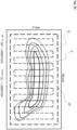
- FIG. 1 A first view of a repair area O is shown.
- the repair area O completely covers the surface of the metallic component to be repaired, whereby the edge of the defined repair area O should have a minimum distance to the surface to be repaired.
- the damage D to be repaired on the component is a depression. This depression is completely filled using the method according to the invention, so that the component has a flat surface at the end of the process.
- the tool path PF defines the path that the tool of the manufacturing system takes in a cycle
- the tool path PF is not limited to the Fig. 1
- the tool path PF is not limited to the straight-line configuration shown, but could also include curved sections.
- the tool path PF advantageously includes only straight sections, so that the computational effort can be further reduced.
- the tool path PF can also advantageously be defined as a function of the working diameter (WorkDia).
- the diameter of the manufacturing system is, for example, the diameter of the laser.
- the distance between adjacent segments of the tool path PF is determined based on the diameter of this laser. It is particularly advantageous if the distance between two adjacent line segments of the tool path PF corresponds to at least half the working diameter plus 5%. This particularly advantageous distance has resulted in very reliable repair results.
- the tool path shown for example, comprises a rectangular outer tool path PF and a meandering inner tool path PF, in which the start point and the end point are arranged opposite each other.
- the tool path can be a continuous tool path or can advantageously be divided into several spaced tool paths.
- no line segment of the tool path PF overlaps.
- the tool path PF is defined in such a way that, taking into account the working diameter, the entire area in the repair area O is covered. In both the measuring cycle and the filling cycle, the tool path PF remains unchanged, which further reduces the computational effort and data expenditure.
- Fig. 1 The view shown shows an example of the XY plane, which in this case is a flat plane.
- the deviations of the component surface from a specified dimension, which simultaneously form the data values DW, are measured in the tool direction (e.g., a Z direction).
- the tool direction is, for example, the direction in which the tool of the manufacturing system applies the filler.
- the tool path PF can also be an uninterrupted
- a line path can be a path that runs continuously from a starting point to an end point and (always) includes straight line segments that preferably do not overlap.
- the array generated in the measurement cycle can also be used directly for the fill cycle, corresponding to the path points.
- curved line segments can be used.
- a polynomial curve can be used as a line segment.
- the tool path PF is formed by path points PFp. These path points are arranged in a row, with the path segments PFs between them. These path segments PFs are, in this example, straight line sections.
- the distance between adjacent path points PFp can vary along the tool path, so that optimal path points PFp are provided.
- the path points PFp can be distributed evenly over the entire tool path PF, with at least one path point PFp being provided in each corner of the tool path PF, as is also the case in Fig. 2 is shown. In such a corner point, for example, a change in the direction of the tool path PF may occur.
- the tool path PF which is directly above the damaged area, is preferably a single, uninterrupted tool path, which is traversed once in one direction in a cycle.
- a tool path can be interrupted if the tool has to be set down or retracted (e.g. along the tool direction), so that the application of filler is not possible.
- the tool path is designed such that in a filling cycle only segments are approached in which the filler is to be applied. In such a development, the tool path in the filling cycle can differ from the tool path in the measuring cycle. In addition, the Tool path may vary from fill cycle to fill cycle.
- data values DW are provided, which are determined for each of the path points PFp.
- the process for repairing components using additive manufacturing involves, in a first step, clamping the component to be repaired into the manufacturing system. Once the component is in the manufacturing system, a repair area can be defined that covers the entire (or only a portion) of the component to be repaired. The tool path (PF) can then be defined within this repair area. All of these steps can be considered an initialization process.
- a measuring cycle and several filling cycles can preferably follow fully automatically.
- the manufacturing system can automatically determine the depth values in the Z direction (or generally in the tool direction) at all path points PFp of the tool path PF.
- the data values are thus, for example, the measured values in the Z direction (or generally in the tool direction) at the path points PFp.
- these measured values are stored sequentially in a data array.
- the data array can thus be viewed as an ordered arrangement of measured depth values.
- the depth values can be measured in relation to a predefined zero plane, which, for example, corresponds to an ideal surface depth of the component.
- the first filling cycle can follow directly, in which an additive laser selectively fills the damaged area of the component in the repair area O.
- Such filling cycles are shown in the Figures 3a to 3e .
- the tool of the additive manufacturing system travels the entire tool path PF.
- a comparison of the respective data value with the threshold value is performed.
- the threshold value is set depending on the determined depth of the damage.
- the maximum value in the data array is determined and the threshold value is assumed to be the maximum value (or preferably slightly lower, by around 1%).
- the threshold value has been modified.
- the threshold value has been reduced, for example, by the fill level (e.g., calculated weld thickness) as it was applied in the first filling cycle.
- the fill level e.g., calculated weld thickness
- Fig. 3 The filling cycle shown is used to apply filler to a larger area of the damaged area.
- the laser is activated A both in the area of the laser processing area determined in the first filling cycle and in the additional area beyond it, where the data value of the path points exceeds the threshold.
- Analog is in Fig. 3c and 3D the filling area is increased and the laser is activated in increasingly larger areas.
- FIG. 3e A final filling cycle is shown as an example, in which the laser is essentially continuously activated A. Only in the horizontal sections between two adjacent line segments of the meandering tool path PF is the laser deactivated B in order to further improve the surface quality. increase.
- Fig. 4 A detailed view of a filling cycle is shown.
- the laser is activated A between two adjacent path points PFp when a path point PFp is reached in the laser travel direction that exceeds the threshold value.
- the laser is only deactivated B when a path point PFp is reached where the threshold value is again undershot.
- the laser remains deactivated or is deactivated if it was previously activated.
- the present exemplary embodiment describes the activation and deactivation of the laser as a function of the measured data value exceeding a threshold value. However, it is also possible to do this with the opposite sign. In other words, the measured values in the tool direction can be assumed to be negative values. In such a configuration, the laser is then activated when the threshold is undershot.
- the above description, in which the laser is activated when the data value exceeds a threshold value relates, by way of example, to the amount of the measured depth in the repair area.
- the component surface to be repaired can also be curved in its original form (including three-dimensionally curved).
- the method according to the invention can thus restore the originally curved surface in the repair area.
- the measuring direction preferably corresponds to the tool direction and can preferably be orthogonal to the surface of the component in the measuring cycle so that a desired depth of the damaged area can be determined.
- the tool path can preferably also be in a surface that is parallel to the original (i.e. undamaged) surface of the component.
- the absolute direction of the measurement can therefore change from measuring point to measuring point, for example if measurements are taken along a curved surface. This depth can be filled again accordingly in the filling cycle.
- the application layers of the tool in the filling cycle are preferably applied in the tool direction.
Landscapes
- Engineering & Computer Science (AREA)
- Physics & Mathematics (AREA)
- Manufacturing & Machinery (AREA)
- Materials Engineering (AREA)
- Chemical & Material Sciences (AREA)
- Optics & Photonics (AREA)
- Mechanical Engineering (AREA)
- Automation & Control Theory (AREA)
- Plasma & Fusion (AREA)
- General Physics & Mathematics (AREA)
- Human Computer Interaction (AREA)
- Theoretical Computer Science (AREA)
- Computer Hardware Design (AREA)
- Evolutionary Computation (AREA)
- Geometry (AREA)
- General Engineering & Computer Science (AREA)
- Powder Metallurgy (AREA)
- Numerical Control (AREA)
- Laser Beam Processing (AREA)
Description
- Die vorliegende Erfindung bezieht sich auf eine Vorrichtung und ein Verfahren zur Reparatur von Bauteilen mittels additiver Fertigung und insbesondere zur Reparatur von Vertiefungen in Bauteilen.
- Für die Reparatur von Schäden an Bauteilen wird üblicherweise in einem ersten Schritt eine Ausfräsung der Reparaturstelle vorgenommen. In einem weiteren Schritt wird die ausgefräste Stelle gescannt und ein entsprechendes Computermodell erstellt. Basierend auf diesen Daten wird wiederum ein Strukturmodell erstellt, welches in die Ausfräsung eingesetzt werden kann, um die Schadstelle zu reparieren. Durch einen solchen Reparaturprozess ist es möglich, eine Schadstelle an der Oberfläche eines Bauteils auszubessern, so dass wiederum die ursprüngliche Oberfläche hergestellt werden kann. Die einzusetzende Struktur kann über additive Fertigungsverfahren hergestellt werden und in die Ausfräsung eingebracht werden.
- Ein Reparaturverfahren ist beispielsweise aus der
US 2017/0370221 A1 bekannt. In diesem Verfahren muss in einem ersten Schritt die Fehlstelle von einem zu reparierenden Bauteil entfernt werden. Über ein additives Fertigungsverfahren kann eine reparierte Komponente erstellt werden, so dass das Bauteil wiederum die ursprüngliche Geometrie erhalten kann. Bekannte Verfahren haben jedoch den Nachteil, dass mehrere Datenkonvertierungsschritte und Verarbeitungsschritte der Messdaten nötig sind, um aus den Messdaten des zu reparierenden Bauteils eine Struktur zu erstellen, welche dann mit dem additiven Fertigungsverfahren hergestellt werden kann. Somit wird meist eine Aufbereitung der Daten nötig. Es resultiert somit ein hoher Rechenaufwand und ein hoher Datenaufwand. - Darüber hinaus ist in der
CN 108 340 582 A ein automatisiertes Reparaturverfahren beschrieben, welches mittels Aufnahme von thermischen Infrarotbildern, etwaige Fehlstellen innerhalb des zu reparierenden Bauteils identifizieren und den daraufhin durchzuführenden Reparaturprozess an die identifizierten Fehlstellen anpassen kann. - Zudem wird auch in der
CN 109 676 135 A ein auf einer vorherigen Bildgebung basierender Bearbeitungsprozess vorgestellt, in welchem mithilfe von Grauwert-Bildanalysen, ein Feedback-Reparatur-System generiert wird. Genauer sieht das oben genannte Verfahren vor, zunächst mittels Vergleich von aufgenommenen Bildintensitätsdaten mit vordefinierten Schwellenwerten, bestehende Defekte innerhalb des zu untersuchenden Bauteils zu finden. In einem darauffolgenden Prozess werden zudem die erstellten Informationen an eine Auswerteeinheit weitergegeben, um so einen speziell auf den Defekt angepassten Reparaturprozess zu ermöglichen. - Ferner ist in der
CN 108 489 986 A ein auf Umschmelzung von Bauteilen basierendes Reparatursystem gezeigt, bei welchem zunächst mittels Positionierung eines aus zwei CCD-Kameras bestehenden Aufnahmemoduls, dreidimensionale Schnittzeichnungen von einem zu bearbeitenden Bauteil generiert und diese zur Analyse an einen externen Computer weitergeleitet werden. Darüber hinaus ist besagter Computer konfiguriert, mittels implementierter Bildanalyseprogramme, bestehende Defekte innerhalb des Bauteils zu detektieren und an ein additives Fertigungsgerät samt Laservorrichtung zu vermitteln, sodass ein iterativer Detektions- und Bearbeitungsmechanismus generiert werden kann. - Ausgehend von dem vorgenannten Stand der Technik ist es eine Aufgabe der vorliegenden Erfindung die beschriebenen Probleme zu lösen. Insbesondere ist es eine Aufgabe ein effizientes Verfahren zur Reparatur von Bauteilen mittels additiver Fertigung bereitzustellen sowie eine entsprechende Vorrichtung.
- Zur Lösung der vorstehend genannten Aufgaben der vorliegenden Erfindung werden die Merkmale der unabhängigen Ansprüche vorgeschlagen und bevorzugte Weiterbildungen sind in den abhängigen Ansprüchen.
- Gemäß der vorliegenden Erfindung kann ein Verfahren zur automatisierten Reparatur von Bauteilen mit einem additiven Fertigungssystem einen ersten Schritt umfassen, in dem das schadhafte Bauteil in das Fertigungssystem eingespannt wird. In einem weiteren Schritt kann ein Reparaturbereich festgelegt werden, der die zu reparierende Fläche des Bauteils umfasst. Zudem kann ein Werkzeugpfad innerhalb des Reparaturbereichs festgelegt werden. Der Werkzeugpfad entspricht dem Verfahrweg, den das Werkzeug des Fertigungssystems in einem Zyklus abfährt. In einem weiteren Schritt kann die Beschaffenheit des Bauteils im Reparaturbereich ermittelt werden (= Messzyklus). In einem solchen Messzyklus können Datenwerte bestimmt werden entlang des festgelegten Werkzeugpfads. Die Datenwerte entsprechen der Abweichung der Fläche des Bauteils von einem vorgegebenen Abmaß. Insbesondere kann die ermittelte Abweichung die Tiefe (bzw. der Betrag davon) der Schadstelle an einem Punkt (Messpunkt) sein. In einem weiteren Schritt kann ein selektives Aufbringen von Füllstoff bzw. Füllmaterial durchgeführt werden. Der Füllstoff kann entlang des festgesetzten Werkzeugpfades in zumindest einem Füllzyklus aufgebracht werden. In einem Füllzyklus kann ein Teil oder bevorzugt der gesamte Werkzeugpfad abgefahren werden und dabei kann selektiv das Fertigungssystem zum Aufbringen des Füllstoffs aktiviert werden in Abhängigkeit von der Differenz zwischen dem Datenwert am Pfad und einem vorbestimmten Schwellenwert. Durch dieses vorteilhafte Verfahren ist es möglich, die Daten, welche direkt aus dem Messzyklus resultieren, als direkten Input für den Füllzyklus zu verwenden. Im Messzyklus entsteht somit ein Daten-Array mit Messwerten für verschiedene Pfadpunkte (Messpunkte). Dieses Daten-Array ist wiederum der Input für den Füllzyklus und bestimmt nach einem Vergleich mit einem vorbestimmen Schwellenwert das Aktivieren oder Deaktivieren des Fertigungssystems zum Aufbringen des Füllstoffs.
- Mit anderen Worten fährt das Fertigungssystem im Füllzyklus den festgelegten Werkzeugpfad ab, entlang der Pfadpunkte. Für jeden der Pfadpunkte kann ein Datenwert ermittelt worden sein, welcher mit dem Schwellenwert verglichen wird. Bei Erreichen eines Pfadpunktes wird der Werkzeugkopf, beispielsweise Laser, des additiven Fertigungssystems aktiviert und ein Material kann aufgebracht werden. Bei Erreichen des nächsten Pfadpunktes wiederum wird ein Vergleich durchgeführt, um festzustellen, ob ein Deaktivieren des Werkzeugkopfs stattfindet, oder ob dieser aktiviert bleibt. Vorteilhaft ist es somit möglich, direkt im Messzyklus das Programm für den Füllzyklus zu erstellen, so dass eine weitere Datenkonvertierung nicht nötig ist und die Datenwerte direkt für die Aktivierung bzw. Deaktivierung des Werkzeugs des Fertigungssystems herangezogen werden. Dadurch, dass der Werkzeugpfad sowohl im Messzyklus als auch im Füllzyklus identisch sein kann, kann der Rechenaufwand und der Datenaufwand weiter reduziert werden. Zudem können der Messzyklus und der Füllzyklus automatisch durchgeführt werden, so dass eine im Wesentlichen automatische Reparatur des Bauteils ermöglicht wird. Aufwändige und fehleranfällige Datenumwandlungen von Punktwolken der Messwerte, welche sich aus der Vermessung der Schadstelle des Bauteils ergeben können, sind nicht nötig. Besonders vorteilhaft wird somit ein vereinfachtes Verfahren zur Reparatur von Bauteilen mittels additiver Fertigung erreicht, welches zugleich eine geringere Störanfälligkeit aufweist.
- Der Werkzeugpfad kann eine Vielzahl von Pfadpunkten aufweisen. Im Messzyklus kann eine Abweichung in eine Werkzeugrichtung (beispielsweise eine Z-Richtung) zwischen der Oberfläche des Bauteils und einer gewünschten Form an jedem der Pfadpunkte ermittelt werden. Die Werkzeugrichtung kann beispielsweise die Richtung sein, welche orthogonal zur Bauteiloberfläche im Reparaturbereich ist.
- Vorteilhaft können die Datenwerte die Abweichung der Bauteiloberfläche in der Werkzeugrichtung angeben und die Werkzeugrichtung kann orthogonal zur Werkstückoberfläche (beispielsweise eine XY-Ebene) sein, auf der der Werkzeugpfad liegt. Das Werkzeug des additiven Fertigungssystems, wie beispielsweise ein Laser, wird somit auf der Werkstückoberfläche verfahren, entlang des Werkzeugpfads. Dieser Werkzeugpfad bzw. die Werkstückoberfläche kann bspw. orthogonal zur Werkzeugrichtung sein, welche die Abweichung bestimmt.
- In einem Füllzyklus kann der Füllstoff entlang eines Pfadsegments des festgelegten Werkzeugpfads selektiv aufgebracht werden. Der Füllstoff kann somit während dem Verfahren von einem Pfadpunkt zum benachbarten Pfadpunkt aufgebracht werden. Ein Ausschalten des Werkzeugs des Fertigungssystems zum Aufbringen des Füllstoffs wird am Zielpfadpunkt in Abhängigkeit von der Differenz zwischen dem Datenwert am Zielpfadpunkt und dem vorbestimmten Schwellenwert ermittelt. Fährt beispielsweise das Werkzeug entlang dem Werkzeugpfad von einem Pfadpunkt zum nächsten und wird dabei stets der Schwellenwert überschritten, so kann beispielsweise der Laser ständig aktiviert sein, so dass ein Aufbringen des Füllstoffs stets durchgeführt wird. Als additive Fertigung kann beispielsweise Pulverdüsenauftragschweißen vorgesehen sein. Wird während dem Verfahren ein Pfadpunkt erreicht, an dem der Datenwert geringer als der Schwellenwert ist, so kann ein Ausschalten des Lasers bzw. des Werkzeugkopfes bewirkt werden. Erst bei Erreichen eines weiteren Pfadpunktes, bei dem der zugehörige Datenwert wiederum den Schwellenwert überschreitet, wird wiederum der Laser aktiviert.
- Ein Pfadsegment kann von zwei Pfadpunkten begrenzt sein und das Pfadsegment kann bevorzugt geradlinig verlaufen. Durch diese besonders effiziente und einfache Ausgestaltung der Pfadsegmente, welche zusammengesetzt den Werkzeugpfad bilden, kann eine weitere Vereinfachung des Reparaturverfahrens erreicht werden, da insbesondere gekrümmte Segmente vermieden werden und nur ein Verfahren in einer X-Richtung und in einer Y-Richtung nötig ist. Bevorzugt können die Datenwerte auch gemittelte Werte von Pfadpunkten eines Segments sein. Ein Aktivieren des Werkzeugs kann somit auch segmentweise durchgeführt werden.
- Der Schwellenwert kann in einem Füllzyklus konstant sein. In einem Füllzyklus kann somit das Werkzeug des Fertigungssystems entlang des festgelegten Werkzeugpfads den gesamten Reparaturbereich abfahren, wobei jeder der Datenpunkte mit dem Schwellenwert des Füllzyklus verglichen wird. Nach dem Abschluss des Füllzyklus kann ein weiterer Füllzyklus vorgesehen sein mit einem abgeänderten Schwellenwert. Durch diese Konfiguration der Füllzyklen ist es möglich eine sukzessive Reparatur der Fehlstellen zu ermöglichen. In jeden Füllzyklus ist somit eine Ebene, welche orthogonal zur Werkzeugrichtung ist, definiert. Jede dieser Ebenen hat wiederum einen unterschiedlichen Schwellenwert bis letztlich bei der letzten Ebene ein minimaler Schwellenwert vorliegt, so dass eine finale Oberfläche (bspw. eine plane Oberfläche) des Bauteils im Reparaturbereich erreicht werden kann. Besonders vorteilhaft kann ein zusätzliches Aufmaß nach Erreichen des minimalen Schwellenwertes aufgetragen werden. Beispielsweise kann somit nach Erreichen des minimalen Schwellenwertes in einem (oder mehreren) zusätzlichen Füllzyklus der gesamte Reparaturbereich mit Füllstoff beaufschlagt werden.
- Es können mehrere Füllzyklen durchgeführt werden und der Schwellenwert kann jeweils um einen Dickenwert angepasst werden, bis eine im Wesentlichen gleichmäßige Oberfläche im Reparaturbereich vorliegt. Im Reparaturbereich kann somit die ursprüngliche Oberflächenform (bspw. linear oder gekrümmt) des Bauteils wiederhergestellt werden. Der Dickenwert kann beispielsweise abhängig von einer Höhe des Materials sein, welches im Füllzyklus aufgebracht wird.
- Das Ergebnis des Messzyklus kann ein Array sein, aus den ermittelten Datenwerten. Der Schwellenwert kann für den ersten Füllzyklus basierend auf einem Maximalwert oder einem Minimalwert (Extremwert) des Arrays und einer Konstanten festgelegt werden. Insbesondere wird der Maximalwert des Arrays verwendet, um die tiefste Fehlstelle des Reparaturbereichs zu ermitteln. Abhängig von dieser tiefsten Stelle, kann der Schwellenwert festgelegt werden, so dass im ersten Füllzyklus lediglich ein Auffüllen der tiefsten Schadstellen erreicht wird. Im darauffolgenden Füllzyklus wird wiederum ein reduzierter Schwellenwert verwendet, so dass zusätzliche Bereiche mit Füllmaterial aufgefüllt werden können. Sukzessive durch die Aneinanderreihung der Füllzyklen wird somit ein komplettes Auffüllen der Schadstellen erreicht.
- Der Schwellenwert kann in einem weiteren Füllzyklus um einen Dickenwert reduziert sein, wobei der Dickenwert der Höhe des aufgebrachten Füllstoffs in einem Füllzyklus entspricht, insbesondere an einem Pfadpunkt oder Pfadsegment. Eine solche Höhe ist beispielsweise die Höhe der Schweißnaht.
- Die ermittelten Datenwerte des Messzyklus können direkt für den Füllzyklus verwendet werden. Somit ist ein Konvertieren oder Umwandeln bzw. Digitalisieren der Ergebnisse des Messzyklus nicht nötig. Ein besonders effizientes und einfaches Reparaturverfahren kann somit bereitgestellt werden. Zudem wird die Fehlerhäufigkeit, welche meist aufgrund von Konvertierungsfehlern entstehen können, vermieden.
- Datenwerte können (ohne Datenkonvertierung) zum Vergleich mit dem Schwellenwert im Füllzyklus verwendet werden. Somit werden die unkonvertierten Datenwerte aus dem Messzyklus direkt verwendet, um im Vergleich mit dem Schwellenwert an den jeweiligen Pfadpunkten zu entscheiden, ob das Werkzeug des adaptiven Fertigungssystems aktiviert wird oder deaktiviert wird (d.h. ob Material eingetragen wird).
- Das Verfahren kann vorteilhaft somit ein Verfahren zur Erstellung einer planen und/oder gekrümmten Oberfläche in einem Reparaturbereich sein. Die reparierte Oberflächenform entspricht vorteilhaft einer ursprünglichen Oberflächenform des Bauteils.
- Der Werkzeugpfad kann vorteilhaft unter Berücksichtigung eines Arbeitsdurchmessers des Fertigungssystems festgelegt werden. Ein solcher Arbeitsdurchmesser des adaptiven Fertigungssystems kann beispielsweise der Durchmesser des Lasers sein (beim Pulverdüsenauftragschweißen). Unter Berücksichtigung dieses Arbeitsdurchmessers kann der Werkzeugpfad vorteilhaft derart festgelegt werden, dass der gesamte Reparaturbereich vollständig abgedeckt werden kann.
- Der Werkzeugpfad kann ein nicht überlappender, durchgehender Linienzug sein. Weiter bevorzugt kann der Werkzeugpfad mäanderförmig ausgestaltet sein. Der Werkzeugpfad kann zudem aus Liniensegmenten bestehen, welche jeweils geradlinig verlaufen. Somit kann ein besonders fehlerunanfälliges Verfahren bereitgestellt werden mit einem optimierten Werkzeugpfad. Zudem kann der Werkzeugpfad konturparallel zum Reparaturbereich ausgestaltet sein.
- Der Reparaturbereich kann festgelegt werden, so dass die zu reparierende Fläche des Bauteils vollständig abgedeckt werden kann. Somit kann erreicht werden, dass durch das Verfahren eine plane Oberfläche (oder vorteilhaft auch eine gekrümmte Oberfläche gem. der ursprünglichen Bauteilform) an der Reparaturstelle erzeugt werden kann.
- Vorteilhaft kann in einem finalen Füllzyklus das Werkzeug des additiven Fertigungssystems beim Abfahren des festgelegten Werkzeugpfades durchgehend aktiviert sein. Durch diese Vorgehensweise ist es möglich, sämtliche möglicherweise verbleibenden Unebenheiten auszugleichen. Zudem kann dadurch ein Aufmaß über die gesamte Fläche des Reparaturbereichs bereitgestellt werden.
- Der festgelegte Werkzeugpfad ist vorteilhaft der Verfahrensweg des Werkzeugs des additiven Fertigungssystems und gleichzeitig der Verfahrensweg des Messinstruments für die Bestimmung der Abweichung. Ein Konvertieren des Verfahrenswegs bzw. des Werkzeugpfads ist somit zwischen dem Messzyklus und dem Füllzyklus bzw. sämtlichen Füllzyklen nicht notwendig. Somit kann der Rechenaufwand weiter reduziert werden und die Fehleranfälligkeit auf ein Minimum reduziert werden.
- Das Werkzeug des additiven Fertigungssystems kann entlang des festgelegten Werkzeugpfades von einem Pfadpunkt zu einem benachbarten Pfadpunkt verfahren werden, wobei an jedem Pfadpunkt ein Vergleich des ermittelten Datenwerts des jeweiligen Pfadpunkts mit einem Schwellenwert durchgeführt werden kann und bei Überschreiten des Schwellenwerts kann das Werkzeug aktiviert werden. Beim Unterschreiten des Schwellenwerts wiederum kann das Werkzeug deaktiviert werden (oder umgekehrt, bei umgekehrten Vorzeichen). Vorteilhaft ist es somit möglich durch die Messwerte an den Pfadpunkten direkt ein Befehls-Array bereitzustellen, welches den Laser bzw. das Werkzeug des additiven Fertigungssystems aktiviert oder deaktiviert.
- Besonders vorteilhaft wird der Messzyklus und der anschließende Füllzyklus automatisch durchgeführt und ein manuelles Einschreiten wird somit nicht benötigt. Weiter vorteilhaft wird der Messzyklus und sämtliche darauffolgenden Füllzyklen automatisch durchgeführt. Die Datenwerte sind somit für alle Füllzyklen gleich. Alternativ kann nach den einzelnen Füllzyklen vorteilhaft jeweils ein weiterer Messzyklus vorgesehen sein, für eine verbesserte Genauigkeit.
- Das Verfahren kann ein Verfahren zum Auffüllen von Vertiefungen einer Bauteiloberfläche in einem Schadbereich sein.
- Das Verfahren kann vorteilhaft den Schritt umfassen, Bewegen des Werkzeugs entlang von Pfadpunkten des festgelegten Werkzeugpfads, wobei bei Erreichen eines Pfadpunktes, an dem der Datenwert größer als der Schwellenwert ist, ein Laser aktiviert wird und bei Erreichen eines Pfadpunktes, an dem der Datenwert nicht größer als der Schwellenwert ist, der Laser deaktiviert wird. Es können eine Vielzahl von Füllzyklen vorgesehen werden, wobei der Schwellenwert sich von Füllzyklus zu Füllzyklus reduzieren kann. Vorteilhaft wird der Schwellenwert für den finalen Füllzyklus derart reduziert, dass sämtliche Datenwerte jeglicher Datenpunkte größer als der Schwellenwert sind. Besonders vorteilhaft kann der Schwellenwert derart eingestellt werden, dass mehrere Schichten Aufmaß im Reparaturbereich aufgetragen werden.
- Der festgelegte Werkzeugpfad kann vorteilhaft parallele Segmente umfassen und der Abstand zwischen benachbarten Segmenten kann abhängig vom Arbeitsdurchmesser des Lasers festgelegt werden.
- Das additive Fertigungssystem kann einen Laser umfassen, wobei ein Einschalten und Ausschalten des Lasers an Pfadpunkten in Abhängigkeit vom Ergebnis des Vergleichs zwischen Datenwert am Pfadpunkt und Schwellenwert ist.
- Für den Messzyklus (zur Bestimmung der Datenwerte) kann vorteilhaft ein Messtaster oder ein optischer Sensor verwendet werden. Zudem kann ein kapazitiver und/oder induktiver Sensor für die Bestimmung verwendet werden.
- Vorteilhaft kann eine Vorrichtung zur Datenverarbeitung vorgesehen sein zur Ausführung des oben genannten Verfahrens. Zudem kann ein computerlesbares Speichermedium vorgesehen sein, welches Befehle umfasst, die bei der Ausführung durch einen Computer diesen veranlassen, das oben genannte Verfahren auszuführen. Es kann ein additives Fertigungssystem vorgesehen sein, welches zum Ausführen des oben genannten Verfahrens konfiguriert ist und dazu eine entsprechende Recheneinheit aufweist.
- Im Folgenden wird die Erfindung anhand von Beispielen in Bezug auf die beiliegenden Figuren beschrieben.
-
- Fig. 1:
- zeigt eine Übersicht über eine zu reparierende Fläche mit einem eingezeichneten Werkzeugpfad PF;
- Fig. 2:
- zeigt eine Detailansicht des Werkzeugpfades PF;
- Fig. 3a:
- zeigt eine erste Ansicht in einem Füllzyklus;
- Fig. 3b:
- zeigt eine weitere Ansicht in einem Füllzyklus;
- Fig. 3c:
- zeigt eine weitere Ansicht des Werkzeugpfades im Füllzyklus;
- Fig. 3d:
- zeigt eine Ansicht eines weit fortgeschrittenen Füllzyklus;
- Fig. 3e:
- zeigt einen finalen Füllzyklus;
- Fig. 4:
- zeigt eine Detailansicht des Werkzeugpfades im Füllzyklus;
- Die folgenden Merkmale der Ausführungsbeispiele sind im Ganzen oder teilweise kombinierbar und die vorliegende Erfindung ist in keiner Weise auf die beschriebenen Ausführungsbeispiele beschränkt. In den Zeichnungen werden gleiche bzw. ähnliche Merkmale mit gleichen Bezugszeichen gekennzeichnet.
- Die vorliegende Erfindung betrifft ein optimiertes Verfahren zur automatisierten Reparatur von Bauteilen, welche beispielsweise Schäden aufweisen. Solche Schäden können Ausbuchtungen, Kratzer, Riefen, etc. sein. Um die Vertiefung im Bauteil zu reparieren, wird ein Verfahren vorgeschlagen, bei dem der Rechenaufwand auf ein Minimalmaß reduziert werden kann. Die Datenverarbeitung kann somit auf ein Mindestmaß reduziert werden, so dass gleichzeitig auch die üblicherweise häufig auftretenden Konvertierungsfehler vermieden werden können. Ein zusätzliches Aufbereiten der Messdaten, um daraus ein Modell (bspw. CAD-Modell) zu erstellen, welches für die Reparatur verwendet werden kann, ist nicht nötig, da gemäß der vorliegenden Erfindung direkt die Daten aus dem Messzyklus als Input für einen Füllzyklus verwendet werden. In einem solchen Füllzyklus wird schichtweise Material auf das Bauteil aufgetragen mittels additiver Fertigung. Die vorliegende Erfindung ist besonders vorteilhaft für additive Fertigungsverfahren einsetzbar, welche laserbasiert arbeiten.
- In
Fig. 1 ist eine erste Ansicht eines Reparaturbereichs O dargestellt. Der Reparaturbereich O deckt die zu reparierende Fläche des metallischen Bauteils vollständig ab, wobei der Rand des festgelegten Reparaturbereichs O einen Mindestabstand zur reparierenden Fläche aufweisen sollte. Wie inFig. 1 dargestellt, ist der zu reparierende Schaden D am Bauteil eine Vertiefung. Diese Vertiefung wird mittels des erfindungsgemäßen Verfahrens vollständig aufgefüllt, so dass das Bauteil am Ende des Verfahrens eine plane Oberfläche aufweist. - In
Fig. 1 ist ein beispielhafter Werkzeugpfad PF dargestellt. Der Werkzeugpfad PF legt den Weg fest, den das Werkzeug des Fertigungssystems in einem Zyklus abfährt. Der Werkzeugpfad PF ist jedoch nicht auf die inFig. 1 dargestellte geradlinige Ausgestaltung beschränkt, sondern könnte auch Kurvenstücke umfassen. Vorteilhaft umfasst der Werkzeugpfad PF jedoch ausschließlich geradlinige Abschnitte, so dass der Rechenaufwand weiter reduziert werden kann. Der Werkzeugpfad PF kann vorteilhafterweise auch in Abhängigkeit des Arbeitsdurchmessers (WorkDia) festgelegt werden. Wie inFig. 1 dargestellt, ist der Durchmesser des Fertigungssystems beispielsweise ein Durchmesser des Lasers. Abhängig vom Durchmesser dieses Lasers wird der Abstand zwischen benachbarten Segmenten des Werkzeugpfades PF festgelegt. Besonders vorteilhaft entspricht der Abstand zwischen zwei benachbarten Liniensegmenten des Werkzeugpfades PF zumindest dem halben Arbeitsdurchmesser zzgl. 5%. Durch diesen besonders vorteilhaften Abstand wurden sehr zuverlässige Reparaturergebnisse festgestellt. - Der in
Fig. 1 dargestellte Werkzeugpfad umfasst beispielsweise einen rechteckigen äußeren Werkzeugpfad PF sowie einen mäanderförmigen inneren Werkzeugpfad PF, bei dem der Startpunkt und der Endpunkt gegenüberliegend voneinander angeordnet sind. Der Werkzeugpfad kann ein durchgehender Werkzeugpfad sein oder kann vorteilhaft auch in mehrere beabstandete Werkzeugpfade aufgeteilt sein. Vorteilhaft überlappt sich kein Liniensegment des Werkzeugpfads PF. Der Werkzeugpfad PF ist derart festgelegt, dass unter Berücksichtigung des Arbeitsdurchmessers die gesamte Fläche im Reparaturbereich O abgedeckt wird. Sowohl im Messzyklus als auch im Füllzyklus bleiben der Werkzeugpfad PF unverändert, was den Rechenaufwand und Datenaufwand zusätzlich reduziert. Die inFig. 1 dargestellte Ansicht zeigt beispielhaft die XY-Ebene welche hier eine plane Ebene ist. Die Abweichungen der Fläche des Bauteils von einem vorgegebenen Abmaß, welche gleichzeitig dann die Datenwerte DW bilden, werden in die Werkzeugrichtung (bspw. eine Z-Richtung) gemessen. Die Werkzeugrichtung ist beispielsweise die Richtung in der das Werkzeug des Fertigungssystems den Füllstoff aufträgt. - Besonders vorteilhaft kann der Werkzeugpfad PF auch ein ununterbrochener Linienverlauf sein, welcher durchgehend von einem Startpunkt bis zu einem Endpunkt verläuft und dabei (stets) geradlinige Liniensegmente umfasst, welche sich bevorzugt nicht überlappen. In einem solchen Fall kann das im Messzyklus erzeugte Array auch direkt für den Füllzyklus verwendet werden, in Korrespondenz zu den Pfadpunkten. In einer Weiterbildung können gekrümmte Liniensegmente verwendet werden. Beispielsweise kann ein Polynomzug als Liniensegment verwendet werden.
- In
Fig. 2 ist eine Detailansicht des Reparaturbereichs O dargestellt. Der Werkzeugpfad PF wird dabei gebildet von Pfadpunkten PFp. Diese Pfadpunkte sind aneinandergereiht, wobei zwischen diesen die Pfadsegmente PFs vorliegen. Diese Pfadsegmente PFs sind in diesem Beispiel geradlinige Linienabschnitte. Der Abstand zwischen benachbarten Pfadpunkten PFp kann entlang des Werkzeugpfades variieren, so dass optimale Pfadpunkte PFp vorgesehen sind. Insbesondere können jedoch die Pfadpunkte PFp gleichmäßig über den gesamten Werkzeugpfad PF verteilt werden, wobei zusätzlich in jeder Ecke des Werkzeugpfades PF zumindest ein Pfadpunkt PFp vorgesehen ist, wie dies auch inFig. 2 dargestellt ist. In einem solchen Eckpunkt kann beispielsweise eine Richtungsänderung des Werkzeugpfades PF vorliegen. - In
Fig. 2 sind zudem Pfeile eingezeichnet, welche die Richtung einzeichnen, entlang welcher das Werkzeug des Fertigungssystems, insbesondere der Laser, entlang des Werkzeugpfades PF verfahren wird. Der Werkzeugpfad PF, welcher direkt über der Schadstelle ist, ist bevorzugt ein einzelner, ununterbrochener Werkzeugpfad, welcher in einem Zyklus einmalig entlang einer Richtung durchfahren wird. Beispielsweise kann ein Werkzeugpfad unterbrochen sein, wenn das Werkzeug abgesetzt oder zurückgezogen werden muss (bspw. entlang der Werkzeugrichtung), sodass ein Auftragen von Füllstoff nicht möglich ist. In einer vorteilhaften Weiterentwicklung ist der Werkzeugpfad derart ausgestaltet, dass in einem Füllzyklus lediglich Segmente angefahren werden in denen der Füllstoff aufzutragen ist. In einer solchen Weiterbildung kann sich der Werkzeugpfad im Füllzyklus vom Werkzeugpfad im Messzyklus unterscheiden. Zudem kann sich der Werkzeugpfad von Füllzyklus zu Füllzyklus unterscheiden. - Wie in
Fig. 2 dargestellt, sind Datenwerte DW vorgesehen, welche für jeden der Pfadpunkte PFp ermittelt werden. - Das Verfahren zur Reparatur von Bauteilen mittels additiver Fertigung umfasst in einem ersten Schritt das Einspannen des zu reparierenden Bauteils in das Fertigungssystem. Sobald das Bauteil im Fertigungssystem aufgenommen ist, kann ein Reparaturbereich festgelegt werden, der die gesamte (oder nur einen Teil) zu reparierende Fläche des Bauteils abdeckt. Innerhalb dieses Reparaturbereichs, kann dann der Werkzeugpfad PF festgelegt werden. All diese Schritte können als Initialisierungsprozess angesehen werden.
- Nach der Initialisierung können bevorzugt vollautomatisch ein Messzyklus und mehrere Füllzyklen folgen. In einem Messzyklus kann das Fertigungssystem automatisch die Tiefenwerte in Z-Richtung (oder allgemein in Werkzeugrichtung) an allen Pfadpunkten PFp des Werkzeugpfades PF ermitteln. Dies ist in
Fig. 2 dargestellt mit der Bezeichnung Z_result[n]. Die Datenwerte sind somit beispielsweise die Messwerte in Z-Richtung (oder allgemein in Werkzeugrichtung) an den Pfadpunkten PFp. In einer besonders vorteilhaften Ausgestaltung werden diese Messwerte nacheinander in einem Daten-Array abgespeichert. Das Daten-Array kann somit als eine geordnete Anordnung von gemessenen Tiefenwerten angesehen werden. Die Tiefenwerte können in Relation zu einer vordefinierten Nullebene gemessen werden, welche beispielsweise einer idealen Oberflächentiefe des Bauteils entspricht. - Nachdem die Datenwerte bestimmt sind und ein Daten-Array erstellt ist, kann im direkten Anschluss der erste Füllzyklus folgen, indem über einen additiven Laser selektiv ein Auffüllen der Schadstelle des Bauteils im Reparaturbereich O erfolgt. Solche Füllzyklen sind dargestellt in den
Figuren 3a bis 3e . In einem beispielhaften ersten Füllzyklus, wie er inFig. 3a dargestellt ist, fährt das Werkzeug des additiven Fertigungssystems den gesamten Werkzeugpfad PF ab. Bei jedem erreichten Pfadpunkt PFp wird ein Vergleich des jeweiligen Datenwerts mit dem Schwellenwert durchgeführt. Der Schwellenwert wird festgelegt in Abhängigkeit von der ermittelten Tiefe der Schadstelle. Im ersten Füllzyklus, wie inFig. 3a dargestellt ist, wird der Maximalwert im Daten-Array ermittelt und der Schwellenwert wird als der Maximalwert angenommen (oder bevorzugt etwas niedriger, um rund 1%). Dies hat zur Folge, dass im ersten Füllzyklus lediglich der Schadensbereich, in dem die maximale Tiefe vorliegt, aufgefüllt wird. Sämtliche Bereiche, in denen die Schadstelle weniger tief ist, werden im ersten Füllzyklus nicht mit Füllstoff aufgefüllt. Dies ist auch inFig. 3a dargestellt, bei dem der aktivierte Laser A als durchgezogene Linie eingezeichnet ist, entlang des Werkzeugpfades PF. In Bereichen des Werkzeugpfades, in denen der Schwellenwert nicht erreicht oder überschritten wird, ist der Laser deaktiviert B, was inFig. 3a durch die gestrichelte Linie dargestellt ist. InFig. 3a wird somit lediglich der innerste Bereich der Schadstelle mit Füllmaterial aufgefüllt. - Im darauffolgenden Füllzyklus, wie er in
Fig. 3b dargestellt ist, ist der Schwellenwert abgeändert. Insbesondere ist der Schwellenwert reduziert, beispielsweise um die Füllhöhe (bspw. rechnerische Schweißnahtdicke), wie sie im ersten Füllzyklus aufgebracht wurde. Somit, dadurch, dass der Schwellenwert weiter reduziert wurde, ist im inFig. 3 dargestellten Füllzyklus ein größerer Bereich der Schadstelle mit Füllstoff zu beaufschlagen. Der Laser ist aktiviert A sowohl im Bereich des im ersten Füllzyklus ermittelten Laserbearbeitungsbereichs, als auch den darüber hinausgehenden zusätzlichen Bereich, an dem jeweils der Datenwert der Pfadpunkte die Schwelle überschreitet. - Analog ist in
Fig. 3c und3d jeweils der Füllbereich erhöht und der Laser wird aktiviert A in jeweils größer werdenden Bereichen. - In
Fig. 3e ist beispielhaft ein finaler Füllzyklus dargestellt, bei dem der Laser im Wesentlichen durchgehend aktiviert ist A. Lediglich in den horizontalen Abschnitten zwischen zwei benachbarten Liniensegmenten des mäanderförmigen Werkzeugpfades PF ist der Laser deaktiviert B, um die Oberflächengüte weiter zu erhöhen. - In
Fig. 4 ist eine Detailansicht eines Füllzyklus dargestellt. Der Laser ist aktiviert A zwischen zwei benachbarten Pfadpunkten PFp, wenn in Verfahrensrichtung des Lasers ein Pfadpunkt PFp erreicht wird, der den Schwellenwert überschreitet. Erst wenn ein Pfadpunkt PFp erreicht wird, bei dem der Schwellenwert wiederum unterschritten wird, wird der Laser deaktiviert B. Bei sämtlichen Pfadpunkten, bei denen der Datenwert geringer als der Schwellenwert ist, bleibt der Laser deaktiviert bzw. wird deaktiviert, wenn dieser zuvor aktiviert war. Zwar ist im vorliegenden Ausführungsbeispiel das Aktivieren und Deaktivieren des Lasers in Abhängigkeit vom Überschreiten des gemessenen Datenwerts eines Schwellenwerts beschrieben. Es ist jedoch auch möglich, dies mit umgekehrten Vorzeichen durchzuführen. Mit anderen Worten können die Messwerte in Werkzeugrichtung als negative Werte angenommen werden. In einer solchen Konfiguration wird der Laser dann bei Unterschreiten der Schwelle aktiviert. Die oben genannte Beschreibung hingegen, bei der der Laser aktiviert wird, wenn der Datenwert einen Schwellenwert überschreitet, betrifft jedoch beispielhaft den Betrag der gemessenen Tiefe im Reparaturbereich. - Die zu reparierende Bauteiloberfläche kann in der ursprünglichen Form auch gekrümmt (auch dreidimensional gekrümmt) ausgestaltet sein. Durch das erfindungsgemäße Verfahren kann somit die ursprünglich gekrümmte Oberfläche im Reparaturbereich wiederhergestellt werden. Die Messrichtung entspricht bevorzugt der Werkzeugrichtung und kann im Messzyklus bevorzugt orthogonal zur Oberfläche des Bauteils vorgesehen sein, sodass eine gesuchte Tiefe der Schadstelle ermittelt werden kann. Der Werkzeugpfad kann bevorzugt auch in einer Fläche sein welche parallel zur ursprünglichen (d.h. unversehrten) Oberfläche des Bauteils ist. Von Messpunkt zu Messpunkt kann sich somit die absolute Richtung der Messung verändern, wenn beispielsweise entlang einer gekrümmten Oberfläche gemessen wird. Diese Tiefe kann im Füllzyklus entsprechend wieder aufgefüllt werden. Die Auftragsschichten des Werkzeugs im Füllzyklus werden bevorzugt in Werkzeugrichtung aufgetragen.
Claims (15)
- Verfahren zur automatisierten Reparatur von Bauteilen mit einem additiven Fertigungssystem umfassend die folgenden Schritte:- a) Festlegen eines Reparaturbereichs (O) der die zu reparierende Fläche eines Bauteils umfasst und Festlegen eines Werkzeugpfades (PF) innerhalb des Reparaturbereichs (O);- b) Ermitteln der Beschaffenheit des Bauteils im Reparaturbereich (O) in einem Messzyklus mittels eines Messinstruments des additiven Fertigungssystems durch Bestimmung von Datenwerten (DW) entlang des festgelegten Werkzeugpfades (PF) für die Abweichung der Fläche des Bauteils von einem vorgegebenen Abmaß; und- c) selektives Aufbringen von Füllstoff entlang des festgelegten Werkzeugpfades (PF) mittels eines Werkzeugs des additiven Fertigungssystems in zumindest einem Füllzyklus, wobei in einem Füllzyklus ein Teil oder der gesamte Werkzeugpfad (PF) abgefahren wird und dabei selektiv das Fertigungssystem zum Aufbringen des Füllstoffs aktiviert wird, abhängig von der Differenz zwischen dem Datenwert (DW) und einem vorbestimmbaren Schwellenwert,wobei der Werkzeugpfad (PF) dem Verfahrweg, den das Werkzeug des Fertigungssystems in zumindest einem Füllzyklus abfährt und gleichzeitig dem Verfahrweg, den das Messinstrument für die Bestimmung der Abweichung abfährt, entspricht.
- Verfahren nach einem der vorhergehenden Ansprüche, wobei der Werkzeugpfad (PF) eine Vielzahl von Pfadpunkten (PFp) aufweist und im Schritt b) eine Abweichung an jedem der Pfadpunkte (PFp) in einer Werkzeugrichtung zwischen der Oberfläche des Bauteils und einer gewünschten Form ermittelt wird.
- Verfahren nach einem der vorhergehenden Ansprüche, wobei die Datenwerte (DW) die Abweichung der Bauteiloberfläche in der Werkzeugrichtung angeben und die Werkzeugrichtung orthogonal zu einer gewählten Oberfläche ist, in der der Werkzeugpfad (PF) liegt.
- Verfahren nach einem der vorhergehenden Ansprüche, wobei in einem Füllzyklus der Füllstoff entlang eines Pfadsegments (PFs) des festgelegten Werkzeugpfades (PF) selektiv aufgebracht wird, wenn der ermittelte Datenwert (DW) für das Pfadsegment (PFs) oder einem Pfadpunkt (PFp) des festgelegten Werkzeugpfads (PF) größer oder gleich einem Schwellenwert ist.
- Verfahren nach dem vorhergehenden Anspruch, wobei ein Pfadsegment (PFs) von zwei Pfadpunkten (PFp) begrenzt wird und das Pfadsegment (PFs) bevorzugt geradlinig verläuft; und/oder wobei der Schwellenwert in einem Füllzyklus konstant ist; und/oder wobei mehrere Füllzyklen durchgeführt werden und der Schwellenwert jeweils um einen Dickenwert angepasst wird, bis eine finale Oberfläche im Reparaturbereich vorliegt welche einer Solloberfläche entspricht.
- Verfahren nach einem der vorhergehenden Ansprüche, wobei das Ergebnis des Schritts b) ein Array bestehend aus den ermittelten Datenwerten (DW) ist und der Schwellenwert für den ersten Füllzyklus basierend auf einen Maximalwert oder Minimalwert des Arrays und/oder einer Konstanten festgelegt wird.
- Verfahren nach einem der vorhergehenden Ansprüche, wobei der Schwellenwert in einem weiteren Füllzyklus um einen Dickenwert angepasst wird und wobei der Dickenwert der Höhe des aufgebrachten Füllstoffes in einem Füllzyklus entspricht.
- Verfahren nach einem der vorhergehenden Ansprüche, wobei die ermittelten Datenwerte (DW) des Messzyklus direkt für den Füllzyklus verwendet werden; und/oder wobei die ermittelten Datenwerte (DW) ohne Datenkonvertierung zum Vergleich mit dem Schwellenwert im Füllzyklus verwendet werden.
- Verfahren nach einem der vorhergehenden Ansprüche, wobei der Werkzeugpfad (PF) unter Berücksichtigung eines Arbeitsdurchmessers (WorkDia) des Fertigungsverfahrens, insbesondere eines Durchmessers eines Lasers, festgelegt wird und den gesamten Reparaturbereich (O) abdeckt; und/oder wobei der Werkzeugpfad (PF) ein nicht überlappender, durchgehender Linienzug ist der bevorzugt mäanderförmig ausgestaltet ist; und/oder wobei der festgelegte Werkzeugpfad (PF) der Verfahrweg des Werkzeugs des additiven Fertigungssystems und der Verfahrweg eines Messinstruments für die Bestimmung der Abweichung ist.
- Verfahren nach einem der vorhergehenden Ansprüche, wobei das Werkzeug des additiven Fertigungssystems entlang des festgelegten Werkzeugpfades (PF) von einem Pfadpunkt (PFp) zu einem benachbarten Pfadpunkt (PFp) verfahren wird und an jedem Pfadpunkt (PFp) ein Vergleich des ermittelten Datenwertes (DW) des jeweiligen Pfadpunkt (PFp) und dem Schwellenwert durchgeführt wird und bei Überschreiten des Schwellenwertes das Werkzeug aktiviert wird; und/oder wobei zumindest die Schritte b) und c) vollautomatisch durchführbar sind.
- Verfahren nach einem der vorhergehenden Ansprüche, wobei der Schritt c) umfasst: Bewegen des Werkzeugs entlang von Pfadpunkten (PFp) des festgelegten Werkzeugpfades (PF),wobei bei Erreichen eines Pfadpunktes (PFp), an dem der Datenwert (DW) größer als der Schwellenwert ist, der Laser aktiviert (A) wird und bei Erreichen eines Pfadpunktes (PFp), an dem der Datenwert (DW) nicht größer als der Schwellenwert ist, der Laser deaktiviert (B) wird, undwobei nach einem Füllzyklus ein weiterer Füllzyklus folgt bei dem der Schwellenwert reduziert ist.
- Verfahren nach einem der vorhergehenden Ansprüche, wobei der festgelegte Werkzeugpfad (PF) parallele Segmente umfasst und der Abstand zwischen benachbarten Segmenten abhängig vom Arbeitsdurchmesser des Lasers festgelegt wird; und/oder wobei das additiven Fertigungssystem einen Laser umfasst und der Schritt c) umfasst: Einschalten und Ausschalten des Laser an Pfadpunkten (PFp) in Abhängigkeit vom Ergebnis des Vergleichs zwischen dem Datenwert (DW) am Pfadpunkt (PFp) und Schwellenwert; und/oder wobei zur Bestimmung der Abweichung ein Messtaster, ein optischer Sensor, ein kapazitiver Sensor, oder ein induktiver Sensor verwendet wird.
- Additives Fertigungssystem mit einer Vorrichtung zur Datenverarbeitung umfassend Mittel zur Ausführung des Verfahrens nach Anspruch 1.
- Computerlesbares Speichermedium, umfassend Befehle, die bei der Ausführung durch einen Computer diesen veranlassen, das Verfahren nach Anspruch 1 auszuführen.
- Verwendung eines Additiven Fertigungssystems nach Anspruch 13, zur Reparatur von Bauteilen mittels Pulverdüsenauftragschweißen.
Applications Claiming Priority (2)
| Application Number | Priority Date | Filing Date | Title |
|---|---|---|---|
| DE102019121947.7A DE102019121947B3 (de) | 2019-08-14 | 2019-08-14 | Vorrichtung und verfahren zur reparatur von bauteilen mittels additiver fertigung |
| PCT/EP2020/071274 WO2021028216A1 (de) | 2019-08-14 | 2020-07-28 | Vorrichtung und verfahren zur reparatur von bauteilen mittels additiver fertigung |
Publications (2)
| Publication Number | Publication Date |
|---|---|
| EP4014097A1 EP4014097A1 (de) | 2022-06-22 |
| EP4014097B1 true EP4014097B1 (de) | 2025-06-18 |
Family
ID=71994472
Family Applications (1)
| Application Number | Title | Priority Date | Filing Date |
|---|---|---|---|
| EP20753299.5A Active EP4014097B1 (de) | 2019-08-14 | 2020-07-28 | Vorrichtung und verfahren zur reparatur von bauteilen mittels additiver fertigung |
Country Status (7)
| Country | Link |
|---|---|
| US (1) | US11819916B2 (de) |
| EP (1) | EP4014097B1 (de) |
| JP (1) | JP7412533B2 (de) |
| KR (1) | KR102810028B1 (de) |
| CN (1) | CN114503113B (de) |
| DE (1) | DE102019121947B3 (de) |
| WO (1) | WO2021028216A1 (de) |
Families Citing this family (4)
| Publication number | Priority date | Publication date | Assignee | Title |
|---|---|---|---|---|
| WO2025072924A1 (en) * | 2023-09-29 | 2025-04-03 | Carnegie Mellon University | System and method for manufacturing |
| CN118003031B (zh) * | 2024-04-09 | 2024-06-14 | 中国长江电力股份有限公司 | 一种增材修复轴瓦的自适应加工方法 |
| JP7810781B1 (ja) | 2024-12-27 | 2026-02-03 | ヤマザキマザック株式会社 | 欠陥補修方法、複合加工装置、コンピュータプログラム |
| CN120362885B (zh) * | 2025-05-28 | 2026-06-12 | 中国长江电力股份有限公司 | 一种基于三维测量的接力器缸体内壁划痕机器人自适应增减材修复方法 |
Citations (1)
| Publication number | Priority date | Publication date | Assignee | Title |
|---|---|---|---|---|
| CN108489986A (zh) * | 2018-03-19 | 2018-09-04 | 长沙理工大学 | 一种增材制造在线检测及修复方法 |
Family Cites Families (20)
| Publication number | Priority date | Publication date | Assignee | Title |
|---|---|---|---|---|
| US7039485B2 (en) * | 2004-03-12 | 2006-05-02 | The Boeing Company | Systems and methods enabling automated return to and/or repair of defects with a material placement machine |
| US8379204B1 (en) * | 2007-08-17 | 2013-02-19 | Gsi Group Corporation | System and method for automatic laser beam alignment |
| US9272369B2 (en) * | 2012-09-12 | 2016-03-01 | Siemens Energy, Inc. | Method for automated superalloy laser cladding with 3D imaging weld path control |
| US9764517B2 (en) * | 2013-01-07 | 2017-09-19 | Bae Systems Plc | Object production using an additive manufacturing process and quality assessment of the object |
| US10065375B2 (en) * | 2014-06-04 | 2018-09-04 | Mitsubishi Hitachi Power Systems, Ltd. | Additive manufacturing system, modeling-data providing apparatus and providing method |
| US20160159011A1 (en) * | 2014-12-04 | 2016-06-09 | Caterpillar Inc. | Vision System for Selective Tridimensional Repair Using Additive Manufacturing |
| US20160318129A1 (en) * | 2015-05-01 | 2016-11-03 | General Electric Company | System and method for multi-laser additive manufacturing |
| ES2991050T3 (es) | 2015-06-03 | 2024-12-02 | Renishaw Plc | Un dispositivo y procedimiento de generación y visualización de datos relacionados con un procedimiento de fabricación aditiva |
| US10875093B2 (en) * | 2015-07-17 | 2020-12-29 | Applied Materials, Inc. | Selective material dispensing in additive manufacturing |
| EP3378039A1 (de) * | 2015-11-16 | 2018-09-26 | Materialise N.V. | Fehlerdetektion in verfahren zur generativen fertigung |
| US20170370221A1 (en) * | 2016-06-24 | 2017-12-28 | General Electric Company | Methods for repairing a damaged component of an engine |
| US10216165B2 (en) * | 2016-09-06 | 2019-02-26 | Cc3D Llc | Systems and methods for controlling additive manufacturing |
| WO2018154658A1 (ja) * | 2017-02-22 | 2018-08-30 | 三菱電機株式会社 | エレベーターの補修装置 |
| EP3441162A1 (de) * | 2017-08-11 | 2019-02-13 | Siemens Aktiengesellschaft | Verfahren zur generativen fertigung einer struktur auf einer bestehenden komponente aus dem pulverbett |
| EP3482853A1 (de) | 2017-11-13 | 2019-05-15 | Renishaw PLC | Vorrichtung und verfahren zur generativen fertigung |
| JP2019104981A (ja) * | 2017-12-14 | 2019-06-27 | キヤノン株式会社 | 三次元造形装置および三次元造形物の製造方法 |
| CN108340582A (zh) * | 2018-02-09 | 2018-07-31 | 中国商用飞机有限责任公司北京民用飞机技术研究中心 | 增材制造的方法、装置、控制装置、存储介质及制造系统 |
| CN108672951A (zh) * | 2018-06-04 | 2018-10-19 | 广东水利电力职业技术学院(广东省水利电力技工学校) | 一种全自动激光切割系统及控制方法 |
| CN109676135A (zh) * | 2018-11-28 | 2019-04-26 | 大连理工大学 | 一种激光增材制造视觉灰度值差异在线监测与缺陷修复装置 |
| CN109684709B (zh) * | 2018-12-20 | 2022-12-30 | 中国民航大学 | 一种航空发动机叶片修复的自适应定位方法 |
-
2019
- 2019-08-14 DE DE102019121947.7A patent/DE102019121947B3/de active Active
-
2020
- 2020-07-28 CN CN202080057482.8A patent/CN114503113B/zh active Active
- 2020-07-28 WO PCT/EP2020/071274 patent/WO2021028216A1/de not_active Ceased
- 2020-07-28 EP EP20753299.5A patent/EP4014097B1/de active Active
- 2020-07-28 US US17/634,846 patent/US11819916B2/en active Active
- 2020-07-28 KR KR1020227007915A patent/KR102810028B1/ko active Active
- 2020-07-28 JP JP2022509037A patent/JP7412533B2/ja active Active
Patent Citations (1)
| Publication number | Priority date | Publication date | Assignee | Title |
|---|---|---|---|---|
| CN108489986A (zh) * | 2018-03-19 | 2018-09-04 | 长沙理工大学 | 一种增材制造在线检测及修复方法 |
Also Published As
| Publication number | Publication date |
|---|---|
| KR102810028B1 (ko) | 2025-05-20 |
| JP2022544531A (ja) | 2022-10-19 |
| CN114503113A (zh) | 2022-05-13 |
| US20220281004A1 (en) | 2022-09-08 |
| CN114503113B (zh) | 2025-07-15 |
| DE102019121947B3 (de) | 2020-12-10 |
| US11819916B2 (en) | 2023-11-21 |
| KR20220049012A (ko) | 2022-04-20 |
| WO2021028216A1 (de) | 2021-02-18 |
| JP7412533B2 (ja) | 2024-01-12 |
| EP4014097A1 (de) | 2022-06-22 |
Similar Documents
| Publication | Publication Date | Title |
|---|---|---|
| EP3432266B1 (de) | Verfahren und vorrichtung zum erkennen von fehlstellen | |
| DE102019121947B3 (de) | Vorrichtung und verfahren zur reparatur von bauteilen mittels additiver fertigung | |
| EP2042259B1 (de) | Vorrichtung und Verfahren zum Laser-Schneiden | |
| EP3240994B1 (de) | Erfassung von geometrischen abweichungen einer bewegungsführung bei einem koordinatenmessgerät oder einer werkzeugmaschine | |
| EP3768454B1 (de) | Verfahren zur automatischen ermittlung optimaler schweissparameter für die durchführung einer schweissung an einem werkstück | |
| WO2017081029A2 (de) | Automatisches detektieren und robotergestütztes bearbeiten von oberflächendefekten | |
| EP2311583B1 (de) | Verfahren zur Bestimmung der Dicke eines Werkstückes mit einer Biegemaschine und eine solche Biegemaschine | |
| EP3403051B1 (de) | Verfahren und vorrichtung zum vorgeben von vorgabedaten für eine vermessung eines zu vermessenden werkstücks durch ein koordinatenmessgerät und/oder für eine auswertung von messergebnissen einer vermessung eines vermessenen werkstücks durch ein koordinatenmessgerät | |
| EP3877107B1 (de) | Verfahren zum betreiben einer fertigungseinrichtung und fertigungseinrichtung zum additiven fertigen eines bauteils aus einem pulvermaterial | |
| EP3537102B1 (de) | Verfahren und anordnung zum erhöhen des durchsatzes bei einer ausreichenden messgenauigkeit bei der werkstückvermessung | |
| EP4235325B1 (de) | Verfahren und vorrichtung zur bestimmung von messpunkten einer angepassten messbahn zur vermessung eines messobjekts durch eine koordinatenmesseinrichtung sowie programm | |
| AT515672B1 (de) | Biegepresse | |
| DE102016103055B4 (de) | Verfahren zum Bearbeiten eines Werkstücks sowie eine Vorrichtung zur Durchführung | |
| DE102018108145A1 (de) | Verfahren zur Bearbeitung von Oberflächen von mittels 3D-Druck gefertigten Bauteilen sowie ein solches bearbeitetes Bauteil | |
| DE102013101931B4 (de) | Verfahren und Vorrichtung zum Vermessen eines Werkstücks | |
| EP3795344B1 (de) | Presslinie und verfahren der kontrolle der gepressten teile auf dieser linie | |
| DE102020101422B4 (de) | Verfahren zum automatisierten Vermessen von Schweißlinsen eines im Laser-Powder Bed Fusion Prozess hergestellten Bauteils | |
| DE102010011841B4 (de) | Verfahren zur Validierung eines Messergebnisses eines Koordinatenmessgeräts | |
| EP1893941B1 (de) | Verfahren und vorrichtung zum bestimmen von geometrischen parametern eines konischen messobjekts | |
| EP3654034A1 (de) | Verfahren zum kalibrieren sowie verfahren und vorrichtung zur vermessung | |
| EP4521059A1 (de) | Auswertung von messdaten aus der vermessung eines werkstücks durch zumindest ein koordinatenmessgerät | |
| WO2019081120A1 (de) | Verfahren und vorrichtung zur oberflächenbearbeitung und verfahren zur herstellung eines geformten bauteils | |
| DE102006048030A1 (de) | Vorrichtung und Verfahren zur Ermittlung von Spaltmaß und Bündigkeit angrenzender Bauteile | |
| DE102023134519A1 (de) | Vorrichtung für dreidimensionale additive Druckoperationen und Verfahren zum Steuern einer Vorrichtung | |
| DE102023105685A1 (de) | Messgerät und Verfahren zur Bestimmung eines Messwerts an einem Objekt |
Legal Events
| Date | Code | Title | Description |
|---|---|---|---|
| STAA | Information on the status of an ep patent application or granted ep patent |
Free format text: STATUS: UNKNOWN |
|
| STAA | Information on the status of an ep patent application or granted ep patent |
Free format text: STATUS: THE INTERNATIONAL PUBLICATION HAS BEEN MADE |
|
| PUAI | Public reference made under article 153(3) epc to a published international application that has entered the european phase |
Free format text: ORIGINAL CODE: 0009012 |
|
| STAA | Information on the status of an ep patent application or granted ep patent |
Free format text: STATUS: REQUEST FOR EXAMINATION WAS MADE |
|
| 17P | Request for examination filed |
Effective date: 20220314 |
|
| AK | Designated contracting states |
Kind code of ref document: A1 Designated state(s): AL AT BE BG CH CY CZ DE DK EE ES FI FR GB GR HR HU IE IS IT LI LT LU LV MC MK MT NL NO PL PT RO RS SE SI SK SM TR |
|
| DAV | Request for validation of the european patent (deleted) | ||
| DAX | Request for extension of the european patent (deleted) | ||
| STAA | Information on the status of an ep patent application or granted ep patent |
Free format text: STATUS: EXAMINATION IS IN PROGRESS |
|
| 17Q | First examination report despatched |
Effective date: 20230912 |
|
| REG | Reference to a national code |
Ref country code: DE Ref legal event code: R079 Free format text: PREVIOUS MAIN CLASS: G05B0019230000 Ipc: G05B0019409900 Ref document number: 502020011248 Country of ref document: DE |
|
| GRAP | Despatch of communication of intention to grant a patent |
Free format text: ORIGINAL CODE: EPIDOSNIGR1 |
|
| STAA | Information on the status of an ep patent application or granted ep patent |
Free format text: STATUS: GRANT OF PATENT IS INTENDED |
|
| RIC1 | Information provided on ipc code assigned before grant |
Ipc: B22F 7/06 20060101ALN20250305BHEP Ipc: B23P 6/00 20060101ALN20250305BHEP Ipc: B22F 10/366 20210101ALI20250305BHEP Ipc: B22F 10/25 20210101ALI20250305BHEP Ipc: B23K 26/144 20140101ALI20250305BHEP Ipc: B23K 26/03 20060101ALI20250305BHEP Ipc: B23K 26/342 20140101ALI20250305BHEP Ipc: B33Y 50/02 20150101ALI20250305BHEP Ipc: G05B 19/42 20060101ALI20250305BHEP Ipc: G05B 19/4099 20060101AFI20250305BHEP |
|
| INTG | Intention to grant announced |
Effective date: 20250318 |
|
| GRAS | Grant fee paid |
Free format text: ORIGINAL CODE: EPIDOSNIGR3 |
|
| GRAA | (expected) grant |
Free format text: ORIGINAL CODE: 0009210 |
|
| STAA | Information on the status of an ep patent application or granted ep patent |
Free format text: STATUS: THE PATENT HAS BEEN GRANTED |
|
| AK | Designated contracting states |
Kind code of ref document: B1 Designated state(s): AL AT BE BG CH CY CZ DE DK EE ES FI FR GB GR HR HU IE IS IT LI LT LU LV MC MK MT NL NO PL PT RO RS SE SI SK SM TR |
|
| REG | Reference to a national code |
Ref country code: GB Ref legal event code: FG4D Free format text: NOT ENGLISH |
|
| REG | Reference to a national code |
Ref country code: CH Ref legal event code: EP |
|
| REG | Reference to a national code |
Ref country code: DE Ref legal event code: R096 Ref document number: 502020011248 Country of ref document: DE |
|
| REG | Reference to a national code |
Ref country code: CH Ref legal event code: EP |
|
| REG | Reference to a national code |
Ref country code: IE Ref legal event code: FG4D Free format text: LANGUAGE OF EP DOCUMENT: GERMAN |
|
| PG25 | Lapsed in a contracting state [announced via postgrant information from national office to epo] |
Ref country code: FI Free format text: LAPSE BECAUSE OF FAILURE TO SUBMIT A TRANSLATION OF THE DESCRIPTION OR TO PAY THE FEE WITHIN THE PRESCRIBED TIME-LIMIT Effective date: 20250618 |
|
| PGFP | Annual fee paid to national office [announced via postgrant information from national office to epo] |
Ref country code: DE Payment date: 20250731 Year of fee payment: 6 |
|
| REG | Reference to a national code |
Ref country code: LT Ref legal event code: MG9D |
|
| PG25 | Lapsed in a contracting state [announced via postgrant information from national office to epo] |
Ref country code: GR Free format text: LAPSE BECAUSE OF FAILURE TO SUBMIT A TRANSLATION OF THE DESCRIPTION OR TO PAY THE FEE WITHIN THE PRESCRIBED TIME-LIMIT Effective date: 20250919 Ref country code: NO Free format text: LAPSE BECAUSE OF FAILURE TO SUBMIT A TRANSLATION OF THE DESCRIPTION OR TO PAY THE FEE WITHIN THE PRESCRIBED TIME-LIMIT Effective date: 20250918 |
|
| PG25 | Lapsed in a contracting state [announced via postgrant information from national office to epo] |
Ref country code: BG Free format text: LAPSE BECAUSE OF FAILURE TO SUBMIT A TRANSLATION OF THE DESCRIPTION OR TO PAY THE FEE WITHIN THE PRESCRIBED TIME-LIMIT Effective date: 20250618 |
|
| PGFP | Annual fee paid to national office [announced via postgrant information from national office to epo] |
Ref country code: GB Payment date: 20250811 Year of fee payment: 6 |
|
| PG25 | Lapsed in a contracting state [announced via postgrant information from national office to epo] |
Ref country code: HR Free format text: LAPSE BECAUSE OF FAILURE TO SUBMIT A TRANSLATION OF THE DESCRIPTION OR TO PAY THE FEE WITHIN THE PRESCRIBED TIME-LIMIT Effective date: 20250618 |
|
| PGFP | Annual fee paid to national office [announced via postgrant information from national office to epo] |
Ref country code: FR Payment date: 20250804 Year of fee payment: 6 Ref country code: AT Payment date: 20250905 Year of fee payment: 6 |
|
| PG25 | Lapsed in a contracting state [announced via postgrant information from national office to epo] |
Ref country code: RS Free format text: LAPSE BECAUSE OF FAILURE TO SUBMIT A TRANSLATION OF THE DESCRIPTION OR TO PAY THE FEE WITHIN THE PRESCRIBED TIME-LIMIT Effective date: 20250918 |
|
| REG | Reference to a national code |
Ref country code: NL Ref legal event code: MP Effective date: 20250618 |
|
| PG25 | Lapsed in a contracting state [announced via postgrant information from national office to epo] |
Ref country code: LV Free format text: LAPSE BECAUSE OF FAILURE TO SUBMIT A TRANSLATION OF THE DESCRIPTION OR TO PAY THE FEE WITHIN THE PRESCRIBED TIME-LIMIT Effective date: 20250618 |
|
| PG25 | Lapsed in a contracting state [announced via postgrant information from national office to epo] |
Ref country code: NL Free format text: LAPSE BECAUSE OF FAILURE TO SUBMIT A TRANSLATION OF THE DESCRIPTION OR TO PAY THE FEE WITHIN THE PRESCRIBED TIME-LIMIT Effective date: 20250618 |
|
| PG25 | Lapsed in a contracting state [announced via postgrant information from national office to epo] |
Ref country code: PT Free format text: LAPSE BECAUSE OF FAILURE TO SUBMIT A TRANSLATION OF THE DESCRIPTION OR TO PAY THE FEE WITHIN THE PRESCRIBED TIME-LIMIT Effective date: 20251020 |
|
| PG25 | Lapsed in a contracting state [announced via postgrant information from national office to epo] |
Ref country code: IS Free format text: LAPSE BECAUSE OF FAILURE TO SUBMIT A TRANSLATION OF THE DESCRIPTION OR TO PAY THE FEE WITHIN THE PRESCRIBED TIME-LIMIT Effective date: 20251018 |
|
| PG25 | Lapsed in a contracting state [announced via postgrant information from national office to epo] |
Ref country code: SM Free format text: LAPSE BECAUSE OF FAILURE TO SUBMIT A TRANSLATION OF THE DESCRIPTION OR TO PAY THE FEE WITHIN THE PRESCRIBED TIME-LIMIT Effective date: 20250618 |
|
| PGFP | Annual fee paid to national office [announced via postgrant information from national office to epo] |
Ref country code: IT Payment date: 20251015 Year of fee payment: 6 |
|
| PG25 | Lapsed in a contracting state [announced via postgrant information from national office to epo] |
Ref country code: CZ Free format text: LAPSE BECAUSE OF FAILURE TO SUBMIT A TRANSLATION OF THE DESCRIPTION OR TO PAY THE FEE WITHIN THE PRESCRIBED TIME-LIMIT Effective date: 20250618 |
|
| PG25 | Lapsed in a contracting state [announced via postgrant information from national office to epo] |
Ref country code: PL Free format text: LAPSE BECAUSE OF FAILURE TO SUBMIT A TRANSLATION OF THE DESCRIPTION OR TO PAY THE FEE WITHIN THE PRESCRIBED TIME-LIMIT Effective date: 20250618 |
|
| PG25 | Lapsed in a contracting state [announced via postgrant information from national office to epo] |
Ref country code: EE Free format text: LAPSE BECAUSE OF FAILURE TO SUBMIT A TRANSLATION OF THE DESCRIPTION OR TO PAY THE FEE WITHIN THE PRESCRIBED TIME-LIMIT Effective date: 20250618 |
|
| PG25 | Lapsed in a contracting state [announced via postgrant information from national office to epo] |
Ref country code: SK Free format text: LAPSE BECAUSE OF FAILURE TO SUBMIT A TRANSLATION OF THE DESCRIPTION OR TO PAY THE FEE WITHIN THE PRESCRIBED TIME-LIMIT Effective date: 20250618 Ref country code: RO Free format text: LAPSE BECAUSE OF FAILURE TO SUBMIT A TRANSLATION OF THE DESCRIPTION OR TO PAY THE FEE WITHIN THE PRESCRIBED TIME-LIMIT Effective date: 20250618 |
|
| PG25 | Lapsed in a contracting state [announced via postgrant information from national office to epo] |
Ref country code: ES Free format text: LAPSE BECAUSE OF FAILURE TO SUBMIT A TRANSLATION OF THE DESCRIPTION OR TO PAY THE FEE WITHIN THE PRESCRIBED TIME-LIMIT Effective date: 20250618 |
|
| REG | Reference to a national code |
Ref country code: CH Ref legal event code: H13 Free format text: ST27 STATUS EVENT CODE: U-0-0-H10-H13 (AS PROVIDED BY THE NATIONAL OFFICE) Effective date: 20260224 |
|
| PG25 | Lapsed in a contracting state [announced via postgrant information from national office to epo] |
Ref country code: LU Free format text: LAPSE BECAUSE OF NON-PAYMENT OF DUE FEES Effective date: 20250728 |
|
| REG | Reference to a national code |
Ref country code: DE Ref legal event code: R097 Ref document number: 502020011248 Country of ref document: DE |
|
| REG | Reference to a national code |
Ref country code: BE Ref legal event code: MM Effective date: 20250731 |
|
| PG25 | Lapsed in a contracting state [announced via postgrant information from national office to epo] |
Ref country code: MC Free format text: LAPSE BECAUSE OF FAILURE TO SUBMIT A TRANSLATION OF THE DESCRIPTION OR TO PAY THE FEE WITHIN THE PRESCRIBED TIME-LIMIT Effective date: 20250618 |
|
| PG25 | Lapsed in a contracting state [announced via postgrant information from national office to epo] |
Ref country code: DK Free format text: LAPSE BECAUSE OF FAILURE TO SUBMIT A TRANSLATION OF THE DESCRIPTION OR TO PAY THE FEE WITHIN THE PRESCRIBED TIME-LIMIT Effective date: 20250618 |
|
| PG25 | Lapsed in a contracting state [announced via postgrant information from national office to epo] |
Ref country code: BE Free format text: LAPSE BECAUSE OF NON-PAYMENT OF DUE FEES Effective date: 20250731 |
|
| PG25 | Lapsed in a contracting state [announced via postgrant information from national office to epo] |
Ref country code: CH Free format text: LAPSE BECAUSE OF NON-PAYMENT OF DUE FEES Effective date: 20250731 |
|
| PLBE | No opposition filed within time limit |
Free format text: ORIGINAL CODE: 0009261 |
|
| STAA | Information on the status of an ep patent application or granted ep patent |
Free format text: STATUS: NO OPPOSITION FILED WITHIN TIME LIMIT |
|
| REG | Reference to a national code |
Ref country code: CH Ref legal event code: L10 Free format text: ST27 STATUS EVENT CODE: U-0-0-L10-L00 (AS PROVIDED BY THE NATIONAL OFFICE) Effective date: 20260430 |
|
| 26N | No opposition filed |
Effective date: 20260319 |
|
| PG25 | Lapsed in a contracting state [announced via postgrant information from national office to epo] |
Ref country code: LT Free format text: LAPSE BECAUSE OF FAILURE TO SUBMIT A TRANSLATION OF THE DESCRIPTION OR TO PAY THE FEE WITHIN THE PRESCRIBED TIME-LIMIT Effective date: 20250618 |
|
| PG25 | Lapsed in a contracting state [announced via postgrant information from national office to epo] |
Ref country code: IE Free format text: LAPSE BECAUSE OF NON-PAYMENT OF DUE FEES Effective date: 20250728 |
|
| PG25 | Lapsed in a contracting state [announced via postgrant information from national office to epo] |
Ref country code: CY Free format text: LAPSE BECAUSE OF FAILURE TO SUBMIT A TRANSLATION OF THE DESCRIPTION OR TO PAY THE FEE WITHIN THE PRESCRIBED TIME-LIMIT Effective date: 20250618 Ref country code: SE Free format text: LAPSE BECAUSE OF FAILURE TO SUBMIT A TRANSLATION OF THE DESCRIPTION OR TO PAY THE FEE WITHIN THE PRESCRIBED TIME-LIMIT Effective date: 20250618 |