EP4012370B1 - Anomalieerkennungsvorrichtung für schienenfahrzeuge - Google Patents
Anomalieerkennungsvorrichtung für schienenfahrzeuge Download PDFInfo
- Publication number
- EP4012370B1 EP4012370B1 EP19915577.1A EP19915577A EP4012370B1 EP 4012370 B1 EP4012370 B1 EP 4012370B1 EP 19915577 A EP19915577 A EP 19915577A EP 4012370 B1 EP4012370 B1 EP 4012370B1
- Authority
- EP
- European Patent Office
- Prior art keywords
- vehicle
- rail
- rail vehicle
- unit
- abnormality
- Prior art date
- Legal status (The legal status is an assumption and is not a legal conclusion. Google has not performed a legal analysis and makes no representation as to the accuracy of the status listed.)
- Active
Links
Images






Classifications
-
- G—PHYSICS
- G01—MEASURING; TESTING
- G01M—TESTING STATIC OR DYNAMIC BALANCE OF MACHINES OR STRUCTURES; TESTING OF STRUCTURES OR APPARATUS, NOT OTHERWISE PROVIDED FOR
- G01M17/00—Testing of vehicles
- G01M17/08—Railway vehicles
-
- B—PERFORMING OPERATIONS; TRANSPORTING
- B61—RAILWAYS
- B61L—GUIDING RAILWAY TRAFFIC; ENSURING THE SAFETY OF RAILWAY TRAFFIC
- B61L15/00—Indicators provided on the vehicle or train for signalling purposes
- B61L15/0081—On-board diagnosis or maintenance
-
- B—PERFORMING OPERATIONS; TRANSPORTING
- B61—RAILWAYS
- B61L—GUIDING RAILWAY TRAFFIC; ENSURING THE SAFETY OF RAILWAY TRAFFIC
- B61L27/00—Central railway traffic control systems; Trackside control; Communication systems specially adapted therefor
- B61L27/50—Trackside diagnosis or maintenance, e.g. software upgrades
- B61L27/57—Trackside diagnosis or maintenance, e.g. software upgrades for vehicles or trains, e.g. trackside supervision of train conditions
-
- G—PHYSICS
- G01—MEASURING; TESTING
- G01M—TESTING STATIC OR DYNAMIC BALANCE OF MACHINES OR STRUCTURES; TESTING OF STRUCTURES OR APPARATUS, NOT OTHERWISE PROVIDED FOR
- G01M7/00—Vibration-testing of structures; Shock-testing of structures
Definitions
- the present invention relates to an abnormality detection apparatus for at least two rail vehicles.
- CBM Condition Based Maintenance
- Patent Literature 1 Japanese Patent Literature 1
- Patent Literature 2 proposes an abnormality monitoring device which includes: an acceleration data acquisition unit for acquiring measurement data regarding the acceleration of a vehicle; an abnormality presence determination unit for determining the presence or absence of an abnormality on the basis of the comparison between the acceleration and a threshold value; a frequency analysis unit for analyzing the frequency of the acceleration in a case where the abnormality presence determination unit has determined the presence of an abnormality; and an abnormality type specification unit for specifying the type of an abnormality on the basis of the pattern of the frequency.
- Patent Literature 3 proposes a method for the identification of poles and modal vectors of a road or rail vehicle, by means of the analysis of the movements or speeds or accelerations (output of the system) acquired in assigned measuring points of said vehicle, wherein said poles and modal vectors are determined by means of the fitting of the data relating to said outputs of the system on the basis of a mathematical model which describes the interaction between road or railway and said vehicle.
- Patent Literature 4 proposes a railroad vehicle state monitoring device which includes: an amplitude ratio calculator for calculating an amplitude ratio between a vehicle body vibration acceleration and an axle box vibration acceleration of the railroad vehicle; a threshold determination processor for performing determination based on the amplitude ratio and a prescribed threshold; and a threshold determination processor for performing determination based on the axle box vibration acceleration and the prescribed threshold.
- Patent Literature 1 disclosed is an abnormality detection apparatus that detects abnormality of a bogie, using acceleration of a bogie frame, which is acquired by an acceleration sensor provided in a bogie frame, and acceleration of a wheel axle, which is acquired by an acceleration sensor provided in a wheel axle.
- acceleration of a bogie is estimated with a physical model to which acceleration of a wheel axle acquired by an acceleration sensor is input and which outputs acceleration of a bogie in normal operation. Then, depending on whether or not estimated and measured values of the acceleration are close, judgment can be made as to whether or not abnormality occurs in the bogie.
- the present invention has been developed in view of the problems noted above and is intended to provide an abnormality detection apparatus for rail vehicles capable of deciding on abnormality of what portion of a vehicle causing abnormal vibration of a vehicle, when occurring, based on information from sensors installed in vehicle bodies, while curbing costs for installation and maintenance.
- claim 1 provides an abnormality detection apparatus for at least two rail vehicles pertaining to the present invention.
- an abnormality detection apparatus for rail vehicles capable of deciding on abnormality of what portion of a vehicle causing abnormal vibration of a vehicle, when occurring, based on information from sensors installed in vehicle bodies, while curbing costs for installation and maintenance. Thereby, it is also enabled to curtail downtime of vehicles and reduce maintenance cost.
- Rail vehicles are vehicles that are operated to travel along rail tracks laid and include railway vehicles, monorail vehicles, streetcars, new transportation vehicles, etc.
- Railway vehicles are taken as a typical example of the rail vehicles and embodiments of the present invention are described.
- Fig. 1 is a functional block diagram depicting a system configuration of the abnormality detection apparatus for railway vehicles.
- Rail vehicles A and B that travel on a rail track 20 vehicle each have a vehicle body 1 and bogies 16, respectively.
- the vehicle body 1 is mounted on the bogies 16 via air suspension spring 8.
- a bogie 16 is comprised of, inter alia, a bogie frame 11, an air suspension spring 8, a yaw damper 4, an axle box body 12, a wheel axle 13, an axle spring device 14, and an axle box support rubber 15 which serves as a housing of bearings for the wheel axle 13.
- the wheel axle 13 is rotatably held with axle box bodies 12, elastic suspension in a vertical direction is provided by the axle spring device 14 between an axle box body 12 and a bogie frame 11, and elastic suspension in a transverse direction is provided by the axle box support rubber 15.
- the air suspension springs 8 are disposed between the vehicle body 1 and the bogie frames 11 and, through these air suspension springs 8, the vehicle body 1 is elastically supported by the bogie frames 11.
- a vibration data detection unit (a vibration data acquisition unit) 60 is installed to acquire data on vibration of the vehicle body 1.
- a physical quantity that the vibration data detection unit 60 detects to acquire data on vibration is not limited to acceleration; speed, displacement, distortion, sound, etc. may be detected. However, description in the present embodiment assumes that the vibration data detection unit 60 detects acceleration.
- the vibration data detection unit 60 is installed in the vehicle body 1 having relatively plenty of space for installation, the same may also be installed on, inter alia, a bogie frame 11 and an axle box body 12, to enable it to detect vibration of these parts. Description in the present embodiment assumes that the vibration data detection unit 60 was installed in the vehicle body 1.
- vibration data detection unit 60 may be installed in one vehicle, description in the present embodiment assumes that a single vibration data detection unit 60 was installed. Moreover, a position in which the vibration data detection unit 60 is installed may be a central position of the vehicle body 1, a position directly above a bogie 16, an end portion of the vehicle body 1, such as a position where a vehicle equipment compartment is present.
- Vibration data acquisition by the vibration data detection unit 60 is applicable in any of the following directions: in longitudinal, transverse, and vertical directions with respect to a traveling direction of the railway vehicle, translational (longitudinal translational, transverse translational, and vertical translational) directions and a rotational (roll pitch yaw) direction. Description in the present embodiment assumes that the vibration data detection unit 60 detects vibration in a transverse translational direction.
- the vehicle body 1 is equipped with an operation data detection unit (an operation data acquisition unit) 50 having a function to acquire operation data such as traveling speed, a traveling position, and a vehicle occupancy rate from, e.g., an operational administrative system which administrates operation data.
- an operation data detection unit an operation data acquisition unit 50 having a function to acquire operation data such as traveling speed, a traveling position, and a vehicle occupancy rate from, e.g., an operational administrative system which administrates operation data.
- Fig. 1 an example is presented in which two rail vehicles (hereinafter simply referred to as vehicles) are each only equipped with the vibration data detection unit 60 and the operation data detection unit 50; however, three or more multiple vehicles may be equipped with them.
- vehicles two rail vehicles (hereinafter simply referred to as vehicles) are each only equipped with the vibration data detection unit 60 and the operation data detection unit 50; however, three or more multiple vehicles may be equipped with them.
- vibration data detection unit 60 and the operation data detection unit 50 may be provided in multiple vehicles in one train set or can also be provided in each vehicle in different train sets traveling on the same rail track.
- An abnormality cause detection device 30 includes a data analysis unit 100, a comparison processing unit 200, a parameter estimation unit 300, an abnormality cause decision unit 400, and a decision result output unit 500 and these units constitute the abnormality detection apparatus to detect a cause of abnormal vibration of a railway vehicle. Additionally, the parameter estimation unit 300 and the abnormality cause decision unit 400 constitute a diagnosis unit.
- abnormality cause detection device 30 it is desirable to install the abnormality cause detection device 30 in a ground facility such as a rail yard where inspection and maintenance of vehicles are performed; however, that device may be installed as on-vehicle equipment.
- the data analysis unit 100, comparison processing unit 200, parameter estimation unit 300, abnormality cause decision unit 400, and decision result output unit 500 are, for example, configured as those of a computing device to perform processing tasks, which will be described later, according to programs stored within the abnormality cause detection device 30.
- the data analysis unit 100 has a function to acquire, from multiple vehicles, vibration data detected by the vibration data detection unit 60 and operation data detected by the operation data detection unit 50, distinguish whether a subject vehicle is placed in normal condition or abnormal condition, and output vibration data and operation data of the vehicles. A concrete processing flow that is performed by the data analysis unit 100 will be described later.
- the comparison processing unit 200 has a function to acquire vibration data and operation data of the vehicles placed in either of abnormal and normal conditions, which has been output by the data analysis unit 100, and output a result of comparison between a vehicle in abnormal condition and a vehicle in normal condition, based on the acquired data. A concrete processing flow that is performed by the comparison processing unit 200 will be described later.
- the parameter estimation unit 300 has a function to estimate parameters regarding vehicle internal conditions from the result of comparison between a vehicle in abnormal condition and a vehicle in normal condition, which has been output by the comparison processing unit 200.
- the parameters regarding a vehicle internal condition are those that are likely to be a cause of abnormality of vibration of a railway vehicle and refer to, for example, rigidity of an axle box support rubber 15 of a box support device installed in a railway vehicle, an attenuation coefficient of a yaw damper 4, and a wheel thread inclination of a wheel axle 13 among others.
- a concrete processing flow that is performed by the parameter estimation unit 300 will be described later.
- the abnormality cause decision unit 400 has a function to decide on a cause of abnormality from the estimated values of parameters which has been output by the parameter estimation unit 300. A concrete processing flow that is performed by the abnormality cause decision unit 400 will be described later.
- the decision result output unit 500 has a function to notify, inter alia, a driver of the vehicle body 1 and a ground operations manager or maintenance personnel of the cause of abnormality which has been output by the abnormality cause decision unit 400 via a monitor, a speaker, etc.
- vibration data detection unit 60 an acceleration sensor in a transverse translational direction (hereinafter referred to as a transverse acceleration sensor) installed directly above the bogie's position was used as the vibration data detection unit 60.
- a vibration waveform a in Fig. 2 is a chart presenting vehicle body's transverse acceleration 621 measured by a transverse acceleration sensor installed in a vehicle A in place corresponding to the rail track position and a vibration waveform b in Fig. 2 is a chart presenting vehicle body's transverse acceleration 622 measured by a transverse acceleration sensor installed in a vehicle B in place corresponding to the rail track position.
- the vibration waveforms a and b it is seen that the higher the measured acceleration, the larger will be waveform amplitude.
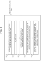
- Fig. 4 is a flowchart to explain a processing procedure of the data analysis unit 100 in the abnormality detection apparatus for railway vehicles in Fig. 1 . Operation according to the flowchart in Fig. 3 is as described below.
- the data analysis unit 100 acquires vehicle body's transverse acceleration measurements from the transverse acceleration sensors in the multiple vehicles and simultaneously acquires operation data such as a traveling position, traveling speed, and a vehicle occupancy rate from the operation data detection unit 50.
- the data analysis unit 100 performs filtering on the vehicle body's transverse acceleration measurements acquired at step S111 using a commonly known filtering technique.
- preprocessing for analysis processing to be performed at step S113 is performed, such as processing to extract only a frequency band that is easily perceivable by human senses from the vehicle body's transverse acceleration measurements and processing to calculate a value of RMS (Root Mean Square) or a maximum of the acceleration measurements.
- RMS Root Mean Square
- the data analysis unit 100 sets a traveling section or the like where vibration is especially large as a representative section from the filtered acceleration measurements and performs processing to extract vehicle body's transverse acceleration data and operation data such as traveling speed and a vehicle occupancy rate of each vehicle of, inter alia, the vehicles A and B in this representative section.
- a representative section can be determined optionally, not limited to a traveling section where vibration is large. Also, there may be one representative section or two or more representative sections.
- a section for which, for each vehicle of, inter alia, the vehicles A and B, data pieces are present, measured under relatively similar measurement conditions including, inter alia, the following: traveling speed of each vehicle is equal or similar, the vehicle occupancy rates of each vehicle are similar, and measurement dates and time of each vehicle are close.
- the data analysis unit 100 compares vehicle body's transverse acceleration data pieces of the respective vehicles in the representative section and performs processing to distinguish whether each vehicle is placed in normal condition or abnormal condition.
- a threshold based processing may be performed, i.e., a threshold of vehicle body's acceleration is set beforehand and a determination is made as to whether or not the threshold is exceeded; alternatively, a commonly known method may be used, i.e., distinguishing is performed using a method such as Malanobis-Taguchi System.
- the vehicle B producing large vibration that exceeds a threshold 922 which is presented in Fig. 2 should be judged to be placed in "abnormal condition" and the vehicle A whose vibration does not exceed the threshold 922 in "normal condition".
- the data analysis unit 100 outputs the vehicle body's transverse acceleration data and operation data in the representative section, extracted at step S113, in addition to distinguishing information as to whether each vehicle is placed in "normal condition” or "abnormal condition” to the comparison processing unit 200.
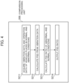
- Fig. 4 is a flowchart to explain a processing procedure of the comparison processing unit 200 in the abnormality detection apparatus for railway vehicles in Fig. 1 . Operation according to the flowchart in Fig. 4 is as described below.
- the comparison processing unit 200 acquires the distinguishing information, inter alia, indicating that the vehicle A is placed in normal condition and the vehicle B is placed in abnormal condition and the vehicle body's transverse acceleration data and operation data in the representative section.
- the comparison processing unit 200 calculates vehicle body's transverse acceleration PSD (Power Spectrum Density) with respect to vehicle body's transverse acceleration of each vehicle.
- PSD Power Spectrum Density
- the PSD is a spectral function that gives expression as a power value per unit frequency width (a width of 1 Hz).
- the calculation gives a result as vehicle body's transverse acceleration PSD 721 of a vehicle placed in normal condition, as is presented in Fig. 5A ; for the vehicle B, the calculation gives a result as vehicle body's transverse acceleration PSD 722 of a vehicle placed in abnormal condition, as is presented in Fig. 5B .
- the vehicle body's transverse acceleration PSD 722 of the vehicle B becomes larger than the vehicle body's transverse acceleration PSD 721 of the vehicle A.
- the comparison processing unit 200 a calculates a PSD ratio 821 that is a ratio between the vehicle body's transverse acceleration PSD 721 of the vehicle A placed in normal condition and the vehicle body's transverse acceleration PSD 722 of the vehicle B placed in abnormal condition, as in Fig. 6 .
- This PSD ratio 821 indicates a frequency band in which PSD in abnormal condition differs from that in normal condition and a degree of the difference.
- the PSD ratio 821 increases significantly in a frequency band 900, as is evident from Fig. 6 .
- any value indicating a characteristic quantity regarding a change between the abnormal and normal conditions can be used instead of the PSD ratio; as an example, inter alia, a ratio between an RMS value of vehicle body's transverse acceleration in abnormal condition and that in normal condition can be used.
- the comparison processing unit 200 outputs this PSD ratio 821 to the parameter estimation unit 300.
- the parameters to be estimated to identify a cause of abnormality are the spring constant of an axle box support rubber 15, the attenuation coefficient of a yaw damper 4, and the wheel thread inclination of a wheel axle 13.
- the parameter estimation unit 300 acquires the PSD ratio 821 which has been output by the comparison processing unit 200. This is referred to as the measured PSD ratio 821.
- the parameter estimation unit 300 calculates an analytic value of vehicle body's transverse acceleration PSD, when the parameters regarding vehicle internal conditions have values under normal condition.
- This dynamic model is a model for predicting vibration characteristics of a railway vehicle.
- Diverse dynamic models can be used according to a type of vibration that one wants to predict, such as a vehicle transverse dynamic model to predict vehicle body's transverse vibration and a vehicle vertical dynamic model to predict vehicle body's vertical vibration, when a virtual vehicle in which the vehicle body 1, bogies 16, and wheel axles 13 are simulated with rigid bodies, axle box support rubbers 15, yaw dampers 4, and others are simulated with springs and dampers, and the respective rigid bodies are connected with the springs and dampers travels on a virtual rail track that simulates track irregularities, e.g., such as an alignment irregularity of a rail track 20 (a degree of irregularity of the lateral surfaces of rails in a longitudinal direction) and a gauge irregularity (an error in a fundamental dimension of an interval between left and right rails).
- track irregularities e.g., such as an alignment irregularity of a rail track 20 (a degree of irregularity of the lateral surfaces of rail
- the track irregularity data may be used.
- a method may be adopted in which track irregularity data sets typical of track states (such as "good”, “ordinary”, and “poor” states) are prepared beforehand and a virtual rail track is defined by selecting and using one of these sets according to a train line or the like of a vehicle in service.
- an analytic value of vehicle body's transverse acceleration PSD is calculated using a dynamic model.
- a design value or an element test value is used for the spring constant of an axle box support rubber 15 and the attenuation coefficient of a yaw damper 4 and, inter alia, a value in new product condition or a control value in maintenance is used for the wheel thread inclination of a wheel axle 13.
- the parameter estimation unit 300 estimates the parameters for the vehicle placed in abnormal condition.
- the parameter estimation unit 300 sets initially estimated values of the parameters.
- the initially estimated values of the parameters may be either normal values of the parameters or randomly generated values.
- the parameter estimation unit 300 sets the initially estimated values of the spring constant of an axle box support rubber 15, the attenuation coefficient of a yaw damper 4, and the wheel thread inclination of a wheel axle 13 among others.
- the parameter estimation unit 300 estimates the parameters in abnormal condition using the measured PSD ratio 821 processed by the comparison processing unit 200.
- the parameter estimation unit 300 calculates an analytic value of vehicle body's transverse acceleration PSD with the parameters having the initially estimated values by using the dynamic model.
- the parameter estimation unit 300 calculates an analytic PSD ratio 822 that is a ratio between the analytic value of vehicle body's transverse acceleration PSD with the parameters having the initially estimated values and the analytic value of vehicle body's transverse acceleration PSD with the parameters having values under normal condition, calculated at step S312.
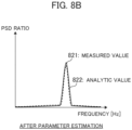
- the parameter estimation unit 300 determines estimated values of the parameters so that the analytic PSD ratio 822 will match the measured PSD ratio 821, i.e., an error will be minimized, as is presented in Figs. 8A and 8B .
- any index that makes it possible to evaluate the error can be used without restrictions; nevertheless, in the present embodiment, a value is used that is obtained by integrating difference between measured PSD ratio 821 and the analytic PSD ratio 822 per frequency of PSD ratio (this value will be referred to as an integrated difference value, hereinafter), as is presented in Figs. 8A and 8B .
- the estimated values of the parameters are obtained to make matching between the measured PSD ratio 821 which was calculated and the analytic PSD ratio 822, as is presented in Fig. 8B , with regard to the spring constant of an axle box support rubber 15, the attenuation coefficient of a yaw damper 4, and the wheel thread inclination of a wheel axle 13 among others.
- Fig. 8A is a characteristic diagram with frequency being plotted on the abscissa and PSD ratio plotted on the ordinate, presenting the measured PSD ratio 821 represented in a sold line and the analytic PSD ratio 822 represented in a dotted line before parameter estimation
- Fig. 8B is a characteristic diagram with frequency being plotted on the abscissa and PSD ratio plotted on the ordinate, presenting the measured PSD ratio 821 represented in a sold line and the analytic PSD ratio 822 represented in a dotted line after parameter estimation.
- the parameter estimation unit 300 After the termination of estimation, at step S315, the parameter estimation unit 300 outputs the estimated values of the parameters to the abnormality cause decision unit 400.
- transverse acceleration sensor was installed in each vehicle body 1.
- transverse acceleration sensors were installed in, inter alia, the vehicle body 1, bogies 16, and axle box bodies 12 respectively, by updating the parameters so that an analytic value will match multiple measured values of transverse acceleration detected from these sensors, it is possible to make the accuracy of parameter estimation higher.
- the abnormality cause decision unit 400 acquires the estimated values of the parameters which have been output by the parameter estimation unit 300.
- the abnormality cause decision unit 400 acquires the estimated values of the following: the spring constant of an axle box support rubber 15, the attenuation coefficient of a yaw damper 4, and the wheel thread inclination of a wheel axle 13.
- the abnormality cause decision unit 400 calculates a ratio between the estimated and normal values of each parameter.
- the abnormality cause decision unit 400 compares this ratio with a preset threshold with respect to each parameter and judges a parameter as normal or abnormal.
- the abnormality cause decision unit 400 judges the parameter as normal (step S414). On the other hand, for a parameter of which this ratio exceeds the threshold, the abnormality cause decision unit 400 judges the parameter as abnormal (step S415).
- the abnormality cause decision unit 400 outputs a parameter judged as abnormal as a cause of abnormality to the decision result output unit 500.
- Fig. 10 is a schematic diagram which schematically represents an example of judging a parameter as normal or abnormal in step S413 and represents a relationship between the ratio between the estimated and normal values of a parameter and the threshold with regard to elements that may be a possible cause of abnormality, such as spring rigidity of an axle box support rubber 15, the attenuation coefficient of a yaw damper 4 and the wheel thread inclination.
- the attenuation coefficient of a yaw damper 4 is judged as abnormal, as the ratio between the estimated and normal values of this parameter exceeds the threshold 91. Then, a result of decision that a decrease in the attenuation coefficient of a yaw damper 4 is a cause of abnormality is output from the abnormality cause decision unit 400 to the decision result output unit 500.
- the parameter deviates from its normal value to a larger extent; therefore, the abnormality extent of the parameter can be evaluated on how large the ratio is.
- the decision result output unit 500 notifies, inter alia, a vehicle driver and a ground operations manager or maintenance personnel of this result of estimating the cause of abnormality through the use of a commonly known communication technology.
- the abnormality detection apparatus for railway vehicles of the present embodiment is capable of estimating a cause of abnormality, like a decrease in the attenuation coefficient of a yaw damper 4.
- An abnormality detection apparatus for vehicles pertaining to the present embodiment has the same configuration as described for the foregoing first embodiment; however, its parameter estimation unit 300 performs processing which will be described below with a flowchart in Fig. 11 . And now, only details that differ from the first embodiment are mainly described below.
- a step S312a is added as processing that is performed by the parameter estimation unit 300 described in the first embodiment without using track irregularity data prepared beforehand, such as measured data, with regard to track irregularity data which is used for analysis with a dynamic model.
- the parameter estimation unit 300 acquires the measured PSD ratio 821 processed by the comparison processing unit 200, as is the case for the first embodiment.
- the parameter estimation unit 300 performs processing to identify track irregularities, based on a measured value of vehicle body's transverse acceleration PSD of a vehicle placed in normal condition.
- the parameter estimation unit 300 performs the processing to identify track irregularity data so that the measured value of vehicle body's transverse acceleration PSD of the vehicle will match an analytic value of vehicle body's transverse acceleration PSD of the vehicle calculated with a dynamic model.
- track irregularity data is to be identified from vehicle body's transverse acceleration PSD of the vehicle A placed in normal condition.
- the parameter estimation unit 300 performs the same processing as in the first embodiment using the track irregularity data identified at step S312a.
- vehicle body's transverse acceleration PSD Although an example of using vehicle body's transverse acceleration PSD was described for the present embodiment, no limitation to vehicle body's transverse acceleration PSD is intended, provided that track irregularity data can be identified.
- the abnormality detection apparatus for railway vehicles of the present embodiment is capable of deciding on a cause of abnormality without preparing track irregularity data beforehand.
- An abnormality detection apparatus for vehicles pertaining to the present embodiment has the same configuration as described for the foregoing first embodiment; however, its parameter estimation unit 300 performs processing which will be described below with a flowchart in Fig. 12 . And now, only details that differ from the first embodiment are mainly described below.
- step S314a and step S315a are added as processing that is performed by the parameter estimation unit 300 in a case where accuracy of estimating the parameters is low; these steps are added to the abnormality detection apparatus of the foregoing embodiments.
- parameter estimation unit 300 estimates the parameters so that an integrated difference value between the measured PSD ratio 821 and the analytic PSD ratio 822 of PSD ratio will be minimized.
- the integrated difference value becomes an index indicating estimation accuracy.
- step S314a if this integrated difference value is less than or equal to a preset threshold, the parameter estimation unit 300 judges that the estimation accuracy is more than or equal to a reference level and outputs the estimated values of the parameters to the abnormality cause decision unit 400 at step S315, as is the case for the first embodiment.
- the parameter estimation unit 300 judges that the estimation accuracy is lower than the reference level and outputs only information that the vehicle is abnormal, but does not output the estimated values of the parameters (including a parameter estimated to be a cause of abnormality)
- the abnormality detection apparatus for railway vehicles of the present embodiment is capable of outputting at least abnormality occurring in the vehicle without stopping abnormality detection, even in a case where the accuracy of estimating the parameters is not sufficient.
- abnormality cause detection device 50 operation data detection unit, 60 vibration data detection unit, 100 data analysis unit, 200 comparison processing unit, 300 parameter estimation unit, 400 abnormality cause decision unit, 500 decision result output unit.
Landscapes
- Engineering & Computer Science (AREA)
- Physics & Mathematics (AREA)
- General Physics & Mathematics (AREA)
- Health & Medical Sciences (AREA)
- Biomedical Technology (AREA)
- General Health & Medical Sciences (AREA)
- Mechanical Engineering (AREA)
- Electric Propulsion And Braking For Vehicles (AREA)
Claims (12)
- Anomaliedetektionsvorrichtung für zumindest zwei Schienenfahrzeuge (A, B), umfassend:eine Vibrationsdatenerfassungseinheit (60), die Vibrationsdaten der Schienenfahrzeuge (A, B) erfasst;eine Betriebsdatenerfassungseinheit (50), die Betriebsdaten der Schienenfahrzeuge (A, B) erfasst; undeine Datenanalyseeinheit (100), die beruhend auf den Vibrationsdaten und den Betriebsdaten erkennt, ob jedes aus den Schienenfahrzeugen (A, B), die auf demselben Gleis (20) fahren, sich in einem normalen oder anormalen Zustand befindet, und Vibrationsdaten der Schienenfahrzeuge (A, B) in Verbindung mit einem normalen oder anormalen Zustand extrahiert, dadurch gekennzeichnet, dass die Vorrichtung ferner Folgendes umfasst:eine Vergleichsverarbeitungseinheit (200), welche die Vibrationsdaten eines Schienenfahrzeugs (A), das sich in einem normalen Zustand befindet, und die Vibrationsdaten eines Schienenfahrzeugs (B), das sich in einem anormalen Zustand befindet, vergleicht und ein Ergebnis des Vergleichs berechnet; undeine Diagnoseeinheit, die beruhend auf dem Ergebnis des Vergleichs über die Ursache einer Vibrationsanomalie im Schienenfahrzeug (B) entscheidet, bei dem erkannt wurde, dass es sich in einem anormalen Zustand befindet.
- Anomaliedetektionsvorrichtung für zumindest zwei Schienenfahrzeuge (A, B) nach Anspruch 1, wobei die Diagnoseeinheit Folgendes umfasst:eine Parameterschätzungseinheit (300), die Parameter betreffend innere Zustände eines Schienenfahrzeugs (B), das sich in einem anormalen Zustand befindet, beruhend auf dem von der Vergleichsverarbeitungseinheit (200) berechneten Ergebnis des Vergleichs schätzt; undeine Anomalieursacheentscheidungseinheit (400), die über die Ursache einer Vibrationsanomalie im Schienenfahrzeug (B), das sich in einem anormalen Zustand befindet, beruhend auf den geschätzten Parametern entscheidet.
- Anomaliedetektionsvorrichtung für zumindest zwei Schienenfahrzeuge (A, B) nach Anspruch 2, wobei die Parameterschätzungseinheit (300) die Parameter betreffend innere Zustände eines Schienenfahrzeugs (B), das sich in einem anormalen Zustand befindet, beruhend auf einem Leistungsspektrumsdichte-(PSD)-Verhältnis eines Schienenfahrzeugs (A), das sich in einem normalen Zustand befindet, und eines Schienenfahrzeugs (B), das sich in einem anormalen Zustand befindet, schätzt.
- Anomaliedetektionsvorrichtung für zumindest zwei Schienenfahrzeuge (A, B) nach Anspruch 2 oder 3, wobei die Parameterschätzungseinheit (300) die Parameter betreffend innere Bedingungen eines Schienenfahrzeugs (B), das sich in einem anormalen Zustand befindet, beruhend auf einem dynamischen Modell für die Vorhersage von Vibrationseigenschaften eines Schienenfahrzeugs (B), das sich in einem anormalen Zustand befindet, schätzt.
- Anomaliedetektionsvorrichtung für zumindest zwei Schienenfahrzeuge (A, B) nach Anspruch 4, wobei das dynamische Modell ein transversales dynamisches Schienenfahrzeug-Modell oder ein vertikales dynamisches Schienenfahrzeug-Modell ist.
- Anomaliedetektionsvorrichtung für zumindest zwei Schienenfahrzeuge (A, B) nach einem der Ansprüche 2 bis 5, wobei die Anomalieursacheentscheidungseinheit (400) über die Ursache einer Vibrationsanomalie beruhend auf dem Ergebnis eines Vergleichs zwischen geschätzten Werten der Parameter betreffend innere Zustände eines Schienenfahrzeugs (B), das sich in einem anormalen Zustand befindet, die von der Parameterschätzungseinheit (300) geschätzt werden, und Normalwerten davon entscheidet.
- Anomaliedetektionsvorrichtung für zumindest zwei Schienenfahrzeuge (A, B) nach einem der Ansprüche 2 bis 6, wobei die Parameterschätzungseinheit (300) Gleisunregelmäßigkeiten beruhend auf Vibrationsdaten des Schienenfahrzeugs (B), das sich in einem anormalen Zustand befindet, identifiziert.
- Anomaliedetektionsvorrichtung für zumindest zwei Schienenfahrzeuge (A, B) nach einem der Ansprüche 2 bis 7, wobei die Parameterschätzungseinheit (300) die Schätzungsgenauigkeit von geschätzten Werten der Parameter betreffend innere Zustände eines Schienenfahrzeugs (B), das sich in einem anormalen Zustand befindet, bestimmt, einen Parameter, von dem geschätzt wird, dass er eine Ursache für eine Anomalie ist, ausgibt, wenn die bestimmte Schätzungsgenauigkeit größer oder gleich einem Referenzpegel ist, und Informationen, die angeben, dass ein Schienenfahrzeug (B), das sich in einem anormalen Zustand befindet, anormal ist, nur ausgibt, wenn die bestimmte Schätzungsgenauigkeit unter dem Referenzpegel liegt.
- Anomaliedetektionsvorrichtung für zumindest zwei Schienenfahrzeuge (A, B) nach einem der Ansprüche 1 bis 8, wobei die Vibrationsdatenerfassungseinheit (60) Vibrationen eines Fahrzeugkörpers (1), eines Drehgestellrahmens (11) oder eines Achslagerkörpers (12) von jedem Schienenfahrzeug (A, B) detektiert.
- Anomaliedetektionsvorrichtung für zumindest zwei Schienenfahrzeuge (A, B) nach einem der Ansprüche 1 bis 9, wobei die Vibrationsdatenerfassungseinheit (60) und die Betriebsdatenerfassungseinheit (50) in Schienenfahrzeugen (A, B) in einer einzelnen Zuggarnitur oder in Schienenfahrzeugen (A, B) in verschiedenen Zuggarnituren, die auf demselben Eisenbahngleis (20) fahren, bereitgestellt sind.
- Anomaliedetektionsvorrichtung für zumindest zwei Schienenfahrzeuge (A, B) nach einem der Ansprüche 1 bis 10, wobei die Datenanalyseeinheit (100) Vibrationsdaten von jedem Schienenfahrzeug (A, B) in einem repräsentativen Abschnitt, der aus Schienenfahrzeugfahrtabschnitten festgelegt wurde, extrahiert.
- Anomaliedetektionsvorrichtung für zumindest zwei Schienenfahrzeuge (A, B) nach einem der Ansprüche 1 bis 11, wobei die Vergleichsverarbeitungseinheit (200), wenn Vibrationsdaten von jedem Schienenfahrzeug (A, B) über einer Schwelle liegen, urteilt, dass das Schienenfahrzeug (B) sich in einem anormalen Zustand befindet, und, wenn die Vibrationsdaten nicht über der Schwelle liegen, urteilt, dass das Schienenfahrzeug (A) sich in einem normalen Zustand befindet.
Priority Applications (1)
| Application Number | Priority Date | Filing Date | Title |
|---|---|---|---|
| EP25180229.4A EP4592664A1 (de) | 2019-08-07 | 2019-08-07 | Anomalieerkennungsvorrichtung für schienenfahrzeuge |
Applications Claiming Priority (1)
| Application Number | Priority Date | Filing Date | Title |
|---|---|---|---|
| PCT/JP2019/031152 WO2021024423A1 (ja) | 2019-08-07 | 2019-08-07 | 軌条車両の異常検出装置 |
Related Child Applications (1)
| Application Number | Title | Priority Date | Filing Date |
|---|---|---|---|
| EP25180229.4A Division EP4592664A1 (de) | 2019-08-07 | 2019-08-07 | Anomalieerkennungsvorrichtung für schienenfahrzeuge |
Publications (3)
| Publication Number | Publication Date |
|---|---|
| EP4012370A1 EP4012370A1 (de) | 2022-06-15 |
| EP4012370A4 EP4012370A4 (de) | 2023-05-17 |
| EP4012370B1 true EP4012370B1 (de) | 2025-06-04 |
Family
ID=74503992
Family Applications (2)
| Application Number | Title | Priority Date | Filing Date |
|---|---|---|---|
| EP19915577.1A Active EP4012370B1 (de) | 2019-08-07 | 2019-08-07 | Anomalieerkennungsvorrichtung für schienenfahrzeuge |
| EP25180229.4A Pending EP4592664A1 (de) | 2019-08-07 | 2019-08-07 | Anomalieerkennungsvorrichtung für schienenfahrzeuge |
Family Applications After (1)
| Application Number | Title | Priority Date | Filing Date |
|---|---|---|---|
| EP25180229.4A Pending EP4592664A1 (de) | 2019-08-07 | 2019-08-07 | Anomalieerkennungsvorrichtung für schienenfahrzeuge |
Country Status (3)
| Country | Link |
|---|---|
| EP (2) | EP4012370B1 (de) |
| JP (1) | JP6935595B2 (de) |
| WO (1) | WO2021024423A1 (de) |
Families Citing this family (7)
| Publication number | Priority date | Publication date | Assignee | Title |
|---|---|---|---|---|
| JP7570979B2 (ja) * | 2021-06-18 | 2024-10-22 | 株式会社日立製作所 | 乗り心地向上支援装置 |
| WO2023199369A1 (ja) * | 2022-04-11 | 2023-10-19 | 株式会社日立製作所 | 寿命評価装置および方法 |
| JP2023172234A (ja) * | 2022-05-23 | 2023-12-06 | 株式会社日立製作所 | 鉄道車両の状態監視システム |
| JP7843211B2 (ja) * | 2022-10-27 | 2026-04-09 | Astemo株式会社 | 車両用制振装置および鉄道車両 |
| US20250108842A1 (en) * | 2023-09-29 | 2025-04-03 | Robert Bosch Gmbh | Prediction and identification of potential railway system anomalies |
| CN119198145B (zh) * | 2024-11-27 | 2025-02-25 | 常州中量高新技术有限公司 | 一种用于列车制动状态下的智能测试系统 |
| CN121019646B (zh) * | 2025-10-24 | 2025-12-30 | 中数智科(杭州)科技有限公司 | 一种铁路轨道磨耗线检测系统及方法 |
Family Cites Families (9)
| Publication number | Priority date | Publication date | Assignee | Title |
|---|---|---|---|---|
| DE3437661C2 (de) * | 1984-10-13 | 1986-08-14 | Fried. Krupp Gmbh, 4300 Essen | Verfahren zum Bestimmen reparaturbedürftiger Bauteile einer Fahrzeugeinheit |
| JPH1020930A (ja) * | 1996-07-04 | 1998-01-23 | Hitachi Ltd | 予防保全方法 |
| JP3779258B2 (ja) | 2002-11-15 | 2006-05-24 | 川崎重工業株式会社 | 車両の異常検出装置及び車両 |
| JP5432818B2 (ja) * | 2010-05-24 | 2014-03-05 | 株式会社日立製作所 | 鉄道車両の状態監視装置及び状態監視方法、並びに鉄道車両 |
| EP2602168B1 (de) * | 2011-12-07 | 2015-07-22 | Railway Metrics and Dynamics Sweden AB | Verfahren und System zur Erkennung und Analyse von Betriebsproblemen bei Eisenbahndrehgestellen |
| CN103592122B (zh) * | 2013-10-25 | 2017-02-15 | 北京交通大学 | 城市轨道交通列车走行部故障诊断设备及方法 |
| CN108139299B (zh) * | 2015-10-16 | 2021-04-13 | 巴里理工大学 | 用于确定道路或轨道车辆的模态参数并间接表征道路或轨道轮廓的方法 |
| JP6867826B2 (ja) * | 2017-02-23 | 2021-05-12 | 三菱重工エンジニアリング株式会社 | 異常監視装置、異常監視方法およびプログラム |
| JP6986480B2 (ja) * | 2017-04-11 | 2021-12-22 | 公益財団法人鉄道総合技術研究所 | 異常診断装置およびプログラム |
-
2019
- 2019-08-07 EP EP19915577.1A patent/EP4012370B1/de active Active
- 2019-08-07 EP EP25180229.4A patent/EP4592664A1/de active Pending
- 2019-08-07 WO PCT/JP2019/031152 patent/WO2021024423A1/ja not_active Ceased
- 2019-08-07 JP JP2020535259A patent/JP6935595B2/ja active Active
Also Published As
| Publication number | Publication date |
|---|---|
| EP4012370A4 (de) | 2023-05-17 |
| JP6935595B2 (ja) | 2021-09-15 |
| EP4012370A1 (de) | 2022-06-15 |
| JPWO2021024423A1 (ja) | 2021-09-13 |
| WO2021024423A1 (ja) | 2021-02-11 |
| EP4592664A1 (de) | 2025-07-30 |
Similar Documents
| Publication | Publication Date | Title |
|---|---|---|
| EP4012370A1 (de) | Anomalieerkennungsvorrichtung für schienenfahrzeuge | |
| JP4298433B2 (ja) | 鉄道車両の異常検知装置 | |
| JP6838176B2 (ja) | 鉄道車両の異常検出装置および方法 | |
| JP5525404B2 (ja) | 鉄道車両の状態監視装置及び状態監視方法、並びに鉄道車両 | |
| CN109580259A (zh) | 检测车辆悬架系统中的异常的系统和方法 | |
| EP3219574B1 (de) | Verfahren und system zur bestimmung eines vertikalen profils einer schienenfläche | |
| JPH0815098A (ja) | 鉄道車両の乗り心地と異常動揺の検知方法及び車両用緩衝器と軌道の状態判断方法 | |
| KR20210040218A (ko) | 타이어의 가속도 극 값을 이용한 타이어 마모 측정 장치 및 이를 이용한 타이어 마모 측정 방법 | |
| JP7776973B2 (ja) | 状態監視装置及び状態監視方法 | |
| CN102639383A (zh) | 监控有轨车辆的具有至少一个轮组的转向架的状态的方法 | |
| CN105923014B (zh) | 一种基于证据推理规则的轨道高低不平顺幅值估计方法 | |
| JP6078722B2 (ja) | 路面性状計測装置 | |
| JP2008148466A (ja) | 軌道系交通システムの異常診断方法及び異常診断システム | |
| JP2025015512A (ja) | 鉄道車両運行安全診断システムおよび診断方法 | |
| JP2018136270A (ja) | 異常監視装置、異常監視方法およびプログラム | |
| CN110182663A (zh) | 电梯导靴预诊断方法及预诊断系统 | |
| WO2023199369A1 (ja) | 寿命評価装置および方法 | |
| US11958513B2 (en) | Railroad car condition monitoring/analyzing device and method | |
| Elia et al. | Condition monitoring of the railway line and overhead equipment through onboard train measurement-an Italian experience | |
| JP7829414B2 (ja) | 橋桁支承部の異常監視方法及び橋桁支承部の異常監視システム | |
| JP7648474B2 (ja) | 橋桁支承部の異常監視方法及び橋桁支承部の異常監視システム | |
| JP6770414B2 (ja) | 乗り心地測定方法及び装置 | |
| JP7445406B2 (ja) | 監視装置、監視方法及びプログラム | |
| JP2006192993A (ja) | 鉄道車両及びその異常検知方法 | |
| KR200488973Y1 (ko) | 철도차량의 승차감 분석장치 |
Legal Events
| Date | Code | Title | Description |
|---|---|---|---|
| STAA | Information on the status of an ep patent application or granted ep patent |
Free format text: STATUS: UNKNOWN |
|
| STAA | Information on the status of an ep patent application or granted ep patent |
Free format text: STATUS: THE INTERNATIONAL PUBLICATION HAS BEEN MADE |
|
| PUAI | Public reference made under article 153(3) epc to a published international application that has entered the european phase |
Free format text: ORIGINAL CODE: 0009012 |
|
| STAA | Information on the status of an ep patent application or granted ep patent |
Free format text: STATUS: REQUEST FOR EXAMINATION WAS MADE |
|
| 17P | Request for examination filed |
Effective date: 20200825 |
|
| AK | Designated contracting states |
Kind code of ref document: A1 Designated state(s): AL AT BE BG CH CY CZ DE DK EE ES FI FR GB GR HR HU IE IS IT LI LT LU LV MC MK MT NL NO PL PT RO RS SE SI SK SM TR |
|
| DAV | Request for validation of the european patent (deleted) | ||
| DAX | Request for extension of the european patent (deleted) | ||
| A4 | Supplementary search report drawn up and despatched |
Effective date: 20230418 |
|
| RIC1 | Information provided on ipc code assigned before grant |
Ipc: B61K 9/08 20060101ALI20230412BHEP Ipc: B61F 5/24 20060101ALI20230412BHEP Ipc: G01M 17/08 20060101AFI20230412BHEP |
|
| STAA | Information on the status of an ep patent application or granted ep patent |
Free format text: STATUS: EXAMINATION IS IN PROGRESS |
|
| 17Q | First examination report despatched |
Effective date: 20241217 |
|
| GRAP | Despatch of communication of intention to grant a patent |
Free format text: ORIGINAL CODE: EPIDOSNIGR1 |
|
| STAA | Information on the status of an ep patent application or granted ep patent |
Free format text: STATUS: GRANT OF PATENT IS INTENDED |
|
| INTG | Intention to grant announced |
Effective date: 20250204 |
|
| RAP3 | Party data changed (applicant data changed or rights of an application transferred) |
Owner name: HITACHI, LTD. |
|
| GRAS | Grant fee paid |
Free format text: ORIGINAL CODE: EPIDOSNIGR3 |
|
| GRAA | (expected) grant |
Free format text: ORIGINAL CODE: 0009210 |
|
| STAA | Information on the status of an ep patent application or granted ep patent |
Free format text: STATUS: THE PATENT HAS BEEN GRANTED |
|
| AK | Designated contracting states |
Kind code of ref document: B1 Designated state(s): AL AT BE BG CH CY CZ DE DK EE ES FI FR GB GR HR HU IE IS IT LI LT LU LV MC MK MT NL NO PL PT RO RS SE SI SK SM TR |
|
| REG | Reference to a national code |
Ref country code: GB Ref legal event code: FG4D |
|
| REG | Reference to a national code |
Ref country code: CH Ref legal event code: EP |
|
| REG | Reference to a national code |
Ref country code: DE Ref legal event code: R096 Ref document number: 602019070924 Country of ref document: DE |
|
| REG | Reference to a national code |
Ref country code: IE Ref legal event code: FG4D |
|
| REG | Reference to a national code |
Ref country code: NL Ref legal event code: MP Effective date: 20250604 |
|
| PG25 | Lapsed in a contracting state [announced via postgrant information from national office to epo] |
Ref country code: FI Free format text: LAPSE BECAUSE OF FAILURE TO SUBMIT A TRANSLATION OF THE DESCRIPTION OR TO PAY THE FEE WITHIN THE PRESCRIBED TIME-LIMIT Effective date: 20250604 Ref country code: ES Free format text: LAPSE BECAUSE OF FAILURE TO SUBMIT A TRANSLATION OF THE DESCRIPTION OR TO PAY THE FEE WITHIN THE PRESCRIBED TIME-LIMIT Effective date: 20250604 |
|
| REG | Reference to a national code |
Ref country code: LT Ref legal event code: MG9D |
|
| PG25 | Lapsed in a contracting state [announced via postgrant information from national office to epo] |
Ref country code: NO Free format text: LAPSE BECAUSE OF FAILURE TO SUBMIT A TRANSLATION OF THE DESCRIPTION OR TO PAY THE FEE WITHIN THE PRESCRIBED TIME-LIMIT Effective date: 20250904 Ref country code: GR Free format text: LAPSE BECAUSE OF FAILURE TO SUBMIT A TRANSLATION OF THE DESCRIPTION OR TO PAY THE FEE WITHIN THE PRESCRIBED TIME-LIMIT Effective date: 20250905 |
|
| PG25 | Lapsed in a contracting state [announced via postgrant information from national office to epo] |
Ref country code: PL Free format text: LAPSE BECAUSE OF FAILURE TO SUBMIT A TRANSLATION OF THE DESCRIPTION OR TO PAY THE FEE WITHIN THE PRESCRIBED TIME-LIMIT Effective date: 20250604 |
|
| PG25 | Lapsed in a contracting state [announced via postgrant information from national office to epo] |
Ref country code: BG Free format text: LAPSE BECAUSE OF FAILURE TO SUBMIT A TRANSLATION OF THE DESCRIPTION OR TO PAY THE FEE WITHIN THE PRESCRIBED TIME-LIMIT Effective date: 20250604 |
|
| PGFP | Annual fee paid to national office [announced via postgrant information from national office to epo] |
Ref country code: GB Payment date: 20250818 Year of fee payment: 7 |
|
| PG25 | Lapsed in a contracting state [announced via postgrant information from national office to epo] |
Ref country code: HR Free format text: LAPSE BECAUSE OF FAILURE TO SUBMIT A TRANSLATION OF THE DESCRIPTION OR TO PAY THE FEE WITHIN THE PRESCRIBED TIME-LIMIT Effective date: 20250604 |
|
| PG25 | Lapsed in a contracting state [announced via postgrant information from national office to epo] |
Ref country code: RS Free format text: LAPSE BECAUSE OF FAILURE TO SUBMIT A TRANSLATION OF THE DESCRIPTION OR TO PAY THE FEE WITHIN THE PRESCRIBED TIME-LIMIT Effective date: 20250904 |
|
| PG25 | Lapsed in a contracting state [announced via postgrant information from national office to epo] |
Ref country code: LV Free format text: LAPSE BECAUSE OF FAILURE TO SUBMIT A TRANSLATION OF THE DESCRIPTION OR TO PAY THE FEE WITHIN THE PRESCRIBED TIME-LIMIT Effective date: 20250604 |
|
| PG25 | Lapsed in a contracting state [announced via postgrant information from national office to epo] |
Ref country code: NL Free format text: LAPSE BECAUSE OF FAILURE TO SUBMIT A TRANSLATION OF THE DESCRIPTION OR TO PAY THE FEE WITHIN THE PRESCRIBED TIME-LIMIT Effective date: 20250604 |
|
| PG25 | Lapsed in a contracting state [announced via postgrant information from national office to epo] |
Ref country code: PT Free format text: LAPSE BECAUSE OF FAILURE TO SUBMIT A TRANSLATION OF THE DESCRIPTION OR TO PAY THE FEE WITHIN THE PRESCRIBED TIME-LIMIT Effective date: 20251006 |
|
| REG | Reference to a national code |
Ref country code: AT Ref legal event code: MK05 Ref document number: 1800752 Country of ref document: AT Kind code of ref document: T Effective date: 20250604 |
|
| PG25 | Lapsed in a contracting state [announced via postgrant information from national office to epo] |
Ref country code: IS Free format text: LAPSE BECAUSE OF FAILURE TO SUBMIT A TRANSLATION OF THE DESCRIPTION OR TO PAY THE FEE WITHIN THE PRESCRIBED TIME-LIMIT Effective date: 20251004 |
|
| PG25 | Lapsed in a contracting state [announced via postgrant information from national office to epo] |
Ref country code: AT Free format text: LAPSE BECAUSE OF FAILURE TO SUBMIT A TRANSLATION OF THE DESCRIPTION OR TO PAY THE FEE WITHIN THE PRESCRIBED TIME-LIMIT Effective date: 20250604 Ref country code: SM Free format text: LAPSE BECAUSE OF FAILURE TO SUBMIT A TRANSLATION OF THE DESCRIPTION OR TO PAY THE FEE WITHIN THE PRESCRIBED TIME-LIMIT Effective date: 20250604 |
|
| PG25 | Lapsed in a contracting state [announced via postgrant information from national office to epo] |
Ref country code: CZ Free format text: LAPSE BECAUSE OF FAILURE TO SUBMIT A TRANSLATION OF THE DESCRIPTION OR TO PAY THE FEE WITHIN THE PRESCRIBED TIME-LIMIT Effective date: 20250604 |
|
| PG25 | Lapsed in a contracting state [announced via postgrant information from national office to epo] |
Ref country code: EE Free format text: LAPSE BECAUSE OF FAILURE TO SUBMIT A TRANSLATION OF THE DESCRIPTION OR TO PAY THE FEE WITHIN THE PRESCRIBED TIME-LIMIT Effective date: 20250604 |
|
| PG25 | Lapsed in a contracting state [announced via postgrant information from national office to epo] |
Ref country code: SK Free format text: LAPSE BECAUSE OF FAILURE TO SUBMIT A TRANSLATION OF THE DESCRIPTION OR TO PAY THE FEE WITHIN THE PRESCRIBED TIME-LIMIT Effective date: 20250604 Ref country code: RO Free format text: LAPSE BECAUSE OF FAILURE TO SUBMIT A TRANSLATION OF THE DESCRIPTION OR TO PAY THE FEE WITHIN THE PRESCRIBED TIME-LIMIT Effective date: 20250604 |
|
| PG25 | Lapsed in a contracting state [announced via postgrant information from national office to epo] |
Ref country code: IT Free format text: LAPSE BECAUSE OF FAILURE TO SUBMIT A TRANSLATION OF THE DESCRIPTION OR TO PAY THE FEE WITHIN THE PRESCRIBED TIME-LIMIT Effective date: 20250604 |
|
| REG | Reference to a national code |
Ref country code: DE Ref legal event code: R119 Ref document number: 602019070924 Country of ref document: DE |
|
| REG | Reference to a national code |
Ref country code: CH Ref legal event code: H13 Free format text: ST27 STATUS EVENT CODE: U-0-0-H10-H13 (AS PROVIDED BY THE NATIONAL OFFICE) Effective date: 20260324 |
|
| PG25 | Lapsed in a contracting state [announced via postgrant information from national office to epo] |
Ref country code: MC Free format text: LAPSE BECAUSE OF FAILURE TO SUBMIT A TRANSLATION OF THE DESCRIPTION OR TO PAY THE FEE WITHIN THE PRESCRIBED TIME-LIMIT Effective date: 20250604 |
|
| PLBE | No opposition filed within time limit |
Free format text: ORIGINAL CODE: 0009261 |
|
| STAA | Information on the status of an ep patent application or granted ep patent |
Free format text: STATUS: NO OPPOSITION FILED WITHIN TIME LIMIT |
|
| PG25 | Lapsed in a contracting state [announced via postgrant information from national office to epo] |
Ref country code: DK Free format text: LAPSE BECAUSE OF FAILURE TO SUBMIT A TRANSLATION OF THE DESCRIPTION OR TO PAY THE FEE WITHIN THE PRESCRIBED TIME-LIMIT Effective date: 20250604 |
|
| PG25 | Lapsed in a contracting state [announced via postgrant information from national office to epo] |
Ref country code: LU Free format text: LAPSE BECAUSE OF NON-PAYMENT OF DUE FEES Effective date: 20250807 |
|
| REG | Reference to a national code |
Ref country code: CH Ref legal event code: L10 Free format text: ST27 STATUS EVENT CODE: U-0-0-L10-L00 (AS PROVIDED BY THE NATIONAL OFFICE) Effective date: 20260416 |
|
| PG25 | Lapsed in a contracting state [announced via postgrant information from national office to epo] |
Ref country code: CH Free format text: LAPSE BECAUSE OF NON-PAYMENT OF DUE FEES Effective date: 20250831 |
|
| 26N | No opposition filed |
Effective date: 20260305 |