EP4012290A1 - Refrigeration cycle device - Google Patents
Refrigeration cycle device Download PDFInfo
- Publication number
- EP4012290A1 EP4012290A1 EP19940373.4A EP19940373A EP4012290A1 EP 4012290 A1 EP4012290 A1 EP 4012290A1 EP 19940373 A EP19940373 A EP 19940373A EP 4012290 A1 EP4012290 A1 EP 4012290A1
- Authority
- EP
- European Patent Office
- Prior art keywords
- refrigerant
- heat exchanger
- side heat
- air
- water
- Prior art date
- Legal status (The legal status is an assumption and is not a legal conclusion. Google has not performed a legal analysis and makes no representation as to the accuracy of the status listed.)
- Granted
Links
Images
Classifications
-
- F—MECHANICAL ENGINEERING; LIGHTING; HEATING; WEAPONS; BLASTING
- F25—REFRIGERATION OR COOLING; COMBINED HEATING AND REFRIGERATION SYSTEMS; HEAT PUMP SYSTEMS; MANUFACTURE OR STORAGE OF ICE; LIQUEFACTION SOLIDIFICATION OF GASES
- F25B—REFRIGERATION MACHINES, PLANTS OR SYSTEMS; COMBINED HEATING AND REFRIGERATION SYSTEMS; HEAT PUMP SYSTEMS
- F25B41/00—Fluid-circulation arrangements
- F25B41/30—Expansion means; Dispositions thereof
- F25B41/31—Expansion valves
-
- F—MECHANICAL ENGINEERING; LIGHTING; HEATING; WEAPONS; BLASTING
- F25—REFRIGERATION OR COOLING; COMBINED HEATING AND REFRIGERATION SYSTEMS; HEAT PUMP SYSTEMS; MANUFACTURE OR STORAGE OF ICE; LIQUEFACTION SOLIDIFICATION OF GASES
- F25B—REFRIGERATION MACHINES, PLANTS OR SYSTEMS; COMBINED HEATING AND REFRIGERATION SYSTEMS; HEAT PUMP SYSTEMS
- F25B13/00—Compression machines, plants or systems, with reversible cycle
-
- F—MECHANICAL ENGINEERING; LIGHTING; HEATING; WEAPONS; BLASTING
- F25—REFRIGERATION OR COOLING; COMBINED HEATING AND REFRIGERATION SYSTEMS; HEAT PUMP SYSTEMS; MANUFACTURE OR STORAGE OF ICE; LIQUEFACTION SOLIDIFICATION OF GASES
- F25B—REFRIGERATION MACHINES, PLANTS OR SYSTEMS; COMBINED HEATING AND REFRIGERATION SYSTEMS; HEAT PUMP SYSTEMS
- F25B41/00—Fluid-circulation arrangements
- F25B41/40—Fluid line arrangements
-
- F—MECHANICAL ENGINEERING; LIGHTING; HEATING; WEAPONS; BLASTING
- F25—REFRIGERATION OR COOLING; COMBINED HEATING AND REFRIGERATION SYSTEMS; HEAT PUMP SYSTEMS; MANUFACTURE OR STORAGE OF ICE; LIQUEFACTION SOLIDIFICATION OF GASES
- F25B—REFRIGERATION MACHINES, PLANTS OR SYSTEMS; COMBINED HEATING AND REFRIGERATION SYSTEMS; HEAT PUMP SYSTEMS
- F25B2313/00—Compression machines, plants or systems with reversible cycle not otherwise provided for
- F25B2313/003—Indoor unit with water as a heat sink or heat source
-
- F—MECHANICAL ENGINEERING; LIGHTING; HEATING; WEAPONS; BLASTING
- F25—REFRIGERATION OR COOLING; COMBINED HEATING AND REFRIGERATION SYSTEMS; HEAT PUMP SYSTEMS; MANUFACTURE OR STORAGE OF ICE; LIQUEFACTION SOLIDIFICATION OF GASES
- F25B—REFRIGERATION MACHINES, PLANTS OR SYSTEMS; COMBINED HEATING AND REFRIGERATION SYSTEMS; HEAT PUMP SYSTEMS
- F25B2339/00—Details of evaporators; Details of condensers
- F25B2339/04—Details of condensers
- F25B2339/047—Water-cooled condensers
-
- F—MECHANICAL ENGINEERING; LIGHTING; HEATING; WEAPONS; BLASTING
- F25—REFRIGERATION OR COOLING; COMBINED HEATING AND REFRIGERATION SYSTEMS; HEAT PUMP SYSTEMS; MANUFACTURE OR STORAGE OF ICE; LIQUEFACTION SOLIDIFICATION OF GASES
- F25B—REFRIGERATION MACHINES, PLANTS OR SYSTEMS; COMBINED HEATING AND REFRIGERATION SYSTEMS; HEAT PUMP SYSTEMS
- F25B2500/00—Problems to be solved
- F25B2500/01—Geometry problems, e.g. for reducing size
Definitions
- the present disclosure relates to a refrigeration cycle apparatus in which refrigerant circulates in a refrigerant circuit.
- the refrigeration cycle apparatus disclosed in Patent Literature 1 includes a compressor, a refrigerant flow switching device such as a four-way valve, an air-side heat exchanger, a main expansion valve, a water-side heat exchanger, an accumulator, a refrigerant-amount adjustment tank, two sub-expansion valves serving as refrigerant flow control valves, a gas purge circuit, and a heat-source-apparatus control device serving as a controller. Furthermore, the compressor, the refrigerant flow switching device, the air-side heat exchanger, the main expansion valve, the water-side heat exchanger, and the accumulator are sequentially connected by refrigerant pipes to form a main circuit of a refrigerant circuit. In addition, the refrigerant-amount adjustment tank, the sub-expansion valves, and the gas purge circuit form a sub-circuit of the refrigerant circuit.
- the refrigerant-amount adjustment tank included in the refrigeration cycle apparatus is provided in parallel with the main expansion valve, and stores surplus refrigerant that generates because of a difference between an operation state of the cooling operation and that of the heating operation.
- Patent Literature 1 Japanese Patent No. 6479203
- the refrigerant-amount adjustment tank is housed in a machine chamber. That is, the machine chamber needs to secure a space to house the refrigerant-amount adjustment tank. Inevitably, the apparatus is made larger.
- the present disclosure is applied to solve the above problem, and relates to a refrigeration cycle apparatus that can be made smaller.
- a refrigeration cycle apparatus includes a refrigerant circuit in which a compressor, a refrigerant flow switching device, an air-side heat exchanger, an expansion valve, a water-side heat exchanger, and an accumulator are connected by refrigerant pipes and refrigerant is circulated.
- G/A is less than or equal to a predetermined threshold ⁇ , where G [L] is a difference in volume between the air-side heat exchanger and the water-side heat exchanger, and A [L] is a volume of the refrigerant circuit.
- G/A is less than or equal to the predetermined threshold ⁇ . Therefore, the surplus refrigerant that is refrigerant the amount of which corresponds to the difference in volume between the air-side heat exchanger and the water-side heat exchanger can be stored in the refrigerant circuit, that is, the surplus refrigerant can be stored in the compressor, the air-side heat exchanger, the expansion valve, the water-side heat exchanger, the accumulator, and the refrigerant pipes.
- a refrigerant tank configured to store the surplus refrigerant does not need to be provided, and it is not necessary to secure a space to house the refrigerant tank in the machine chamber. Accordingly, the refrigeration cycle apparatus can be made smaller.
- a refrigeration cycle apparatus 100 according to the embodiment will be described.
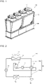
- Fig. 1 is a perspective view illustrating an air-cooled heat pump chiller 101 to which the refrigeration cycle apparatus 100 according to the embodiment is applied.
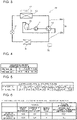
- Fig. 2 is a schematic diagram illustrating an example of the circuit configuration of the refrigeration cycle apparatus 100 according to the embodiment in a cooling operation.
- Fig. 3 is a schematic diagram illustrating an example of the circuit configuration of the refrigeration cycle apparatus 100 according to the embodiment in a heating operation.
- the refrigeration cycle apparatus 100 is applied to, for example, an air-cooled heat pump chiller 101 that is provided as illustrated in Fig. 1 and that cools and heats water to generate cold water and hot water.
- the refrigeration cycle apparatus 100 may be applied to an air-conditioning apparatus that is provided to cool and heat an indoor space.
- a machine chamber 30 that houses a compressor 11, an expansion valve 14, and other components is provided at a lower portion of the air-cooled heat pump chiller 101.
- an air-side heat exchanger 13 is provided on the machine chamber 30, and an air-side air-sending device is provided on the air-side heat exchanger 13.
- the refrigeration cycle apparatus 100 includes the compressor 11, a refrigerant flow switching device 12, the air-side heat exchanger 13, the expansion valve 14, a water-side heat exchanger 15, an accumulator 16, the air-side air-sending device, and a heat-source-apparatus control device 50 serving as a controller.
- the refrigeration cycle apparatus 100 includes a refrigerant circuit in which the compressor 11, the refrigerant flow switching device 12, the air-side heat exchanger 13, the expansion valve 14, the water-side heat exchanger 15, and the accumulator 16 are sequentially connected by refrigerant pipes 20.
- the refrigerant circuit is filled with refrigerant that circulates in the circuit.
- the refrigerant pipes include gas pipes and a liquid pipe.
- the gas pipes are a high-pressure pipe 20a that connects a discharge side of the compressor 11 with the water-side heat exchanger 15 in the heating operation and a low-pressure pipe 20b that connects the air-side heat exchanger 13 with a suction side of the compressor 11 in the heating operation.
- the liquid pipe connects the water-side heat exchanger 15 with the air-side heat exchanger 13.
- refrigerant to be filled in the refrigerant circuit for example, single-component refrigerant such as R-22 or R-134a, pseudo-azeotropic refrigerant mixture such as R-410A and R-404A, or non-azeotropic refrigerant mixture such as R-407C can be used.
- the compressor 11 sucks low-temperature and low-pressure refrigerant, compresses the low-temperature and low-pressure refrigerant to change into high-temperature and high-pressure gas refrigerant, and discharges the high-temperature and high-pressure gas refrigerant.
- the compressor 11 is, for example, an inverter compressor that can be controlled in volume that is a refrigerant sending amount per unit time, by arbitrarily changing a driving frequency.
- the refrigerant flow switching device 12 switches a flow direction of the refrigerant between a flow direction of the refrigerant in the cooling operation and that in the heating operation.
- the refrigerant flow switching device 12 switches the flow direction of the refrigerant such that the gas refrigerant discharged from the compressor 11 flows into the air-side heat exchanger 13, as illustrated in Fig. 2 .
- the refrigerant flow switching device 12 switches the flow direction of the refrigerant such that the gas refrigerant discharged from the compressor 11 flows tin the water-side heat exchanger 15, as illustrated in Fig. 3 .
- the refrigerant flow switching device 12 is, for example, a four-way valve; however, other valves may be used in combination as the refrigerant flow switching device 12.
- the air-side heat exchanger 13 causes heat exchange to be performed between the refrigerant and air that is supplied by, for example, the air-side air-sending device, such as fan, which is provided close to the air-side heat exchanger 13. More specifically, in the cooling operation, the air-side heat exchanger 13 operates as a condenser that radiates heat of the refrigerant to the air to condense the refrigerant. In addition, in the heating operation, the air-side heat exchanger 13 operates as an evaporator that evaporates the refrigerant to cool outdoor air with heat of evaporation at that time.
- the air-side heat exchanger 13 is formed by combining a plurality of plate fins and a plurality of refrigerant pipes.
- the expansion valve 14 has a function of reducing the pressure of refrigerant that flows in the refrigerant circuit and expanding of the refrigerant.
- the expansion valve 14 is, for example, an electronic expansion valve, that is, a valve whose opening degree can be controlled.
- the water-side heat exchanger 15 operates as a condenser or an evaporator, and causes heat exchange to be performed between the refrigerant that flows in the refrigerant circuit and a heat medium such as water.
- the accumulator 16 is provided on the suction side of the compressor 11, which is a low-pressure side of the compressor 11.
- the accumulator 16 accumulates surplus refrigerant that generates because of a difference between an operation state of the cooling operation and an operation state of the heating operation, and surplus refrigerant that generates because of a transient change of the operation.
- the heat-source-apparatus control device 50 controls the entire refrigeration cycle apparatus 100.
- the heat-source-apparatus control device 50 is, for example, dedicated hardware or a central processing unit (CPU, also referred to as a central processing device, a processing device, an arithmetic device, a microprocessor, a microcomputer, or a processor) that executes programs stored in a memory.
- CPU central processing unit
- CPU also referred to as a central processing device, a processing device, an arithmetic device, a microprocessor, a microcomputer, or a processor
- the heat-source-apparatus control device 50 corresponds to, for example, a single circuit, a composite circuit, an application specific integrated circuit (ASIC), a field programmable gate array (FPGA), or a combination thereof.
- Functional units that are implemented by the heat-source-apparatus control device 50 may be individual hardware, or the functional units may be single hardware.
- the functions that are fulfilled by the heat-source-apparatus control device 50 are fulfilled by software, firmware, or a combination of software and firmware.
- the software and the firmware are described as programs and are stored in the memory.
- the CPU reads a program from the memory and executes the read program to fulfill a function of the heat-source-apparatus control device 50 that corresponds to the program.
- the memory is, for example, a nonvolatile or volatile semiconductor memory such as a RAM, a ROM, a flash memory, an EPROM, or an EEPROM. It should be noted that of the functions of the heat-source-apparatus control device 50, a function or functions may be fulfilled by the dedicated hardware, and another function or other functions may be fulfilled by the software or the firmware.
- the heat-source-apparatus control device 50 receives information indicating the results of detection from various kinds of detection units such as a low-pressure sensor (not illustrated) and an outside air temperature sensor (not illustrated). Furthermore, the heat-source-apparatus control device 50 controls a driving frequency of the compressor 11, a rotation speed (including on/off) of the air-side air-sending device, a switching operation of the refrigerant flow switching device 12, the opening degree of the expansion valve 14, and other operations, on the basis of operation information on the refrigeration cycle apparatus 100 that is indicated by the results of the detection and an instruction concerning the operation that is given by a user.
- detection units such as a low-pressure sensor (not illustrated) and an outside air temperature sensor (not illustrated). Furthermore, the heat-source-apparatus control device 50 controls a driving frequency of the compressor 11, a rotation speed (including on/off) of the air-side air-sending device, a switching operation of the refrigerant flow switching device 12, the opening degree of the expansion valve 14, and other operations, on the basis of operation information on
- the amount of refrigerant that is required for the refrigerant circuit in the cooling operation is compared with that in the heating operation, the volume of the water-side heat exchanger 15 can be reduced, since the refrigerant is further efficiently condensed in the water-side heat exchanger 15 than in the air-side heat exchanger 13. Therefore, the amount of the refrigerant that is required for the refrigerant circuit in the heating operation is smaller than that in the cooling operation.
- a refrigerant tank is provided in parallel with the expansion valve 14, and surplus refrigerant that generates in the heating operation is stored in the refrigerant tank.
- the refrigeration cycle apparatus 100 is formed with no refrigerant tank.
- the amount of refrigerant that can be stored between the air-side heat exchanger 13 and the water-side heat exchanger 15 varies between the cooling operation and the heating operation.
- all the surplus refrigerant the amount of which corresponds to the above variance in the amount of the refrigerant can be stored in the refrigerant circuit, that is, in the air-side heat exchanger 13, the water-side heat exchanger 15, the accumulator 16, and the refrigerant pipes 20, it is not necessary to provide a refrigerant tank.
- the refrigerant in the gas pipe is present as gas refrigerant, not liquid refrigerant, to prevent a failure from occurring at the compressor 11 due to a liquid back.
- the refrigerant in the gas pipes included in the refrigerant pipes 20 it is necessary to reduce the pressure in the refrigerant circuit to a predetermined value or less.
- the volume of the entire refrigerant circuit is related to the pressure in the refrigerant circuit. The pressure in the refrigerant circuit is harder to raise, as the volume of the entire refrigerant circuit is increased.
- G [L] is the difference in volume between the air-side heat exchanger 13 and the water-side heat exchanger 15
- a [L] is the volume of the entire refrigerant circuit
- G/A is less than or equal to a predetermined threshold ⁇ , that is, when G/A ⁇ ⁇ is satisfied, it is possible to store all the surplus refrigerant as gas refrigerant in the refrigerant circuit, and it is therefore unnecessary to provide a refrigerant tank in the refrigerant circuit.
- the threshold ⁇ is a threshold at which a refrigerant tank configured to store surplus refrigerant becomes unnecessary, and is a threshold determined for storing all the surplus refrigerant as gas refrigerant in the refrigerant circuit.
- the volume of the entire refrigerant circuit is the total volume of the compressor 11, the air-side heat exchanger 13, the expansion valve 14, the water-side heat exchanger 15, the accumulator 16, and the refrigerant pipes 20.
- Fig. 4 is a diagram indicating volumes of common high-pressure pipes for use in the refrigerant circuit, which correspond to respective sizes of the common high-pressure pipes.
- Fig. 5 is a diagram indicating volumes of common low-pressure pipes for use in the refrigerant circuit, which correspond to respective sizes of the common low-pressure pipes.
- each of the high-pressure pipes is a pipe that connects the discharge side of the compressor with the water-side heat exchanger in the heating operation
- each of the low-pressure pipes is a pipe that connects the air-side heat exchanger with the suction side of the compressor in the heating operation, in a refrigerant circuit configuration similar to the refrigerant circuit configuration of the refrigeration cycle apparatus 100.
- the difference in volume between the air-side heat exchanger and the water-side heat exchanger is set to 5 L.
- the length of each of the refrigerant pipes is set to 1.2 m that corresponds to that of a refrigerant pipe for use in a standard air-cooled heat pump chiller.
- the volume of the air-side heat exchanger, that of the water-side heat exchanger, and that of the accumulator are set to respective values that are determined depending on the performances of the air-side heat exchanger, the water-side heat exchanger and the accumulator. Furthermore, as indicated in Figs.
- the size (outer diameter) of the high-pressure pipe is set to 25.4 mm, 28.6 mm, or 31.75 mm
- the size (outer diameter) of the low-pressure pipe is set to 25.4 mm, 28.6 mm, 31.75 mm, 34.93 mm, 38.1 mm, 41.28 mm, 44.45 mm, or 50.8 mm, based on JIS.
- the size (outer diameter) of the liquid pipe is set to 12.7 mm that is the size of a liquid pipe that can reduce a refrigerant pressure loss of the liquid refrigerant to a specified value or less.
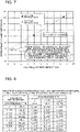
- Fig. 6 is a diagram indicating a relationship between the volume of a refrigerant tank in each of existing apparatuses and the difference in volume between an air-side heat exchanger and a water-side heat exchanger in each existing apparatus.
- air heat exchanger described in Fig. 6 is an abbreviation of the air-side heat exchanger
- water heat exchanger described in Fig. 6 is an abbreviation of the water-side heat exchanger, and the same is true of the following description.
- the volume of an air-side heat exchanger is 19.6 L
- the volume of a water-side heat exchanger is 5.4 L
- the difference in volume between the air-side heat exchanger and the water-side heat exchanger is 14.2 L.
- a refrigerant tank having a volume of 8.5 L is mounted in the existing apparatus A.
- the volume of an air-side heat exchanger is 13.9 L
- the volume of a water-side heat exchanger is 5.4 L
- the difference in volume between the air-side heat exchanger and the water-side heat exchanger is 8.5 L.
- a refrigerant tank having a volume of 4 L is mounted.
- Fig. 7 is a diagram indicating a relationship between the volume of the refrigerant tank and the difference in volume between the air-side heat exchanger and the water-side heat exchanger.
- An equation y of a straight line indicated in Fig. 7 is obtained from the above structures of the existing apparatus A and the existing apparatus B.
- the necessary volume of the refrigerant tank is zero, that is, the refrigerant tank is unnecessary. Therefore, in consideration of individual variability, it is determined that in the case where the difference in volume between the air-side heat exchanger and the water-side heat exchanger is less than or equal to 4 L, the refrigerant tank is unnecessary. Furthermore, the liquid refrigerant can be stored in the refrigerant pipe that extends from the water-side heat exchanger to the expansion valve.
- the expansion valve when the expansion valve is provided close to the air-side heat exchanger, the length of the refrigerant pipe from the water-side heat exchanger to the expansion valve is increased, and the volume of refrigerant that can be accumulated is increased.
- the expansion valve When the expansion valve is provided close to the air-side heat exchanger, and for example, the size (outer diameter) of the liquid pipe is set to 12.7 mm, the volume of the refrigerant pipe from the water-side heat exchanger to the expansion valve is approximately 1 L. Therefore, this value is added to the difference in volume between the air-side heat exchanger and the water-side heat exchanger, thereby obtaining 5 L. Accordingly, as the calculation condition, the difference in volume between the air-side heat exchanger and the water is 5 L.
- Fig. 8 is a diagram indicating thresholds for sizes of the high-pressure pipes and the low-pressure pipes that are indicated regarding their volumes in Figs. 4 and 5 .
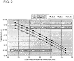
- Fig. 9 is a diagram indicating a relationship between the thresholds and the sizes of the low-pressure pipes. It should be noted that in Fig. 9 , the vertical axis indicates the threshold, and the horizontal axis indicates the size of the low-pressure pipe.
- the threshold ⁇ When the threshold ⁇ is calculated based on the above calculation condition, the threshold ⁇ varies as indicated in Fig. 8 .
- the threshold ⁇ for each of the sizes (outer diameters) of the high-pressure pipes is expressed by the following equation as indicated in Fig. 9 .
- the refrigeration cycle apparatus 100 includes the refrigerant circuit in which the compressor 11, the refrigerant flow switching device 12, the air-side heat exchanger 13, the expansion valve 14, the water-side heat exchanger 15, and the accumulator 16 are connected by the refrigerant pipes 20 and the refrigerant is circulated.
- G [L] is the difference in volume between the air-side heat exchanger 13 and the water-side heat exchanger 15, and A [L] is the volume of the entire refrigerant circuit
- G/A is less than or equal to the predetermined threshold ⁇ .
- G/A is less than or equal to the predetermined threshold ⁇ . Therefore, the surplus refrigerant that is refrigerant the amount of which corresponds to the difference in volume between the air-side heat exchanger 13 and the water-side heat exchanger 15 can be stored in the refrigerant circuit, that is, the surplus refrigerant can be stored in the compressor 11, the air-side heat exchanger 13, the expansion valve 14, the water-side heat exchanger 15, the accumulator 16, and the refrigerant pipes 20. As a result, a refrigerant storage tank does not need to be provided. Accordingly, it is not necessary to secure, in the machine chamber a space for a refrigerant-amount adjustment tank, and the refrigerant cycle apparatus can thus be made smaller.
Landscapes
- Engineering & Computer Science (AREA)
- Physics & Mathematics (AREA)
- Mechanical Engineering (AREA)
- Thermal Sciences (AREA)
- General Engineering & Computer Science (AREA)
- Compression-Type Refrigeration Machines With Reversible Cycles (AREA)
- Other Air-Conditioning Systems (AREA)
Abstract
Description
- The present disclosure relates to a refrigeration cycle apparatus in which refrigerant circulates in a refrigerant circuit.
- In general, in an air-cooled chiller, refrigerant is highly efficiently condensed at a water-side heat exchanger than at an air-side heat exchanger. Thus, the volume of the water-side heat exchanger can be reduced. Furthermore, in a heating operation, the amount of refrigerant that is required for a refrigeration cycle apparatus is smaller than that in a cooling operation. Therefore, in the heating operation in which the water-side heat exchanger operates as a condenser, it is necessary to store surplus refrigerant because a required amount of refrigerant is smaller than that in the cooling operation. In view of the above, a refrigeration cycle apparatus is proposed that can store surplus refrigerant that generates for the above reason (for example, see Patent Literature 1).
- The refrigeration cycle apparatus disclosed in
Patent Literature 1 includes a compressor, a refrigerant flow switching device such as a four-way valve, an air-side heat exchanger, a main expansion valve, a water-side heat exchanger, an accumulator, a refrigerant-amount adjustment tank, two sub-expansion valves serving as refrigerant flow control valves, a gas purge circuit, and a heat-source-apparatus control device serving as a controller. Furthermore, the compressor, the refrigerant flow switching device, the air-side heat exchanger, the main expansion valve, the water-side heat exchanger, and the accumulator are sequentially connected by refrigerant pipes to form a main circuit of a refrigerant circuit. In addition, the refrigerant-amount adjustment tank, the sub-expansion valves, and the gas purge circuit form a sub-circuit of the refrigerant circuit. - The refrigerant-amount adjustment tank included in the refrigeration cycle apparatus is provided in parallel with the main expansion valve, and stores surplus refrigerant that generates because of a difference between an operation state of the cooling operation and that of the heating operation.
- Patent Literature 1:
Japanese Patent No. 6479203 - In the refrigeration cycle apparatus disclosed in
Patent Literature 1, the refrigerant-amount adjustment tank is housed in a machine chamber. That is, the machine chamber needs to secure a space to house the refrigerant-amount adjustment tank. Inevitably, the apparatus is made larger. - The present disclosure is applied to solve the above problem, and relates to a refrigeration cycle apparatus that can be made smaller.
- A refrigeration cycle apparatus according to an embodiment of the present disclosure includes a refrigerant circuit in which a compressor, a refrigerant flow switching device, an air-side heat exchanger, an expansion valve, a water-side heat exchanger, and an accumulator are connected by refrigerant pipes and refrigerant is circulated. G/A is less than or equal to a predetermined threshold χ, where G [L] is a difference in volume between the air-side heat exchanger and the water-side heat exchanger, and A [L] is a volume of the refrigerant circuit.
- In the refrigeration cycle apparatus according to the embodiment of the present disclosure, G/A is less than or equal to the predetermined threshold χ. Therefore, the surplus refrigerant that is refrigerant the amount of which corresponds to the difference in volume between the air-side heat exchanger and the water-side heat exchanger can be stored in the refrigerant circuit, that is, the surplus refrigerant can be stored in the compressor, the air-side heat exchanger, the expansion valve, the water-side heat exchanger, the accumulator, and the refrigerant pipes. As a result, a refrigerant tank configured to store the surplus refrigerant does not need to be provided, and it is not necessary to secure a space to house the refrigerant tank in the machine chamber. Accordingly, the refrigeration cycle apparatus can be made smaller.
-
- [
Fig. 1] Fig. 1 is a perspective view illustrating an air-cooled heat pump chiller to which a refrigeration cycle apparatus according to an embodiment of the present disclosure is applied. - [
Fig. 2] Fig. 2 is a schematic diagram illustrating an example of the circuit configuration of the refrigeration cycle apparatus according to the embodiment in a cooling operation. - [
Fig. 3] Fig. 3 is a schematic diagram illustrating an example of the circuit configuration of the refrigeration cycle apparatus according to the embodiment in a heating operation. - [
Fig. 4] Fig. 4 is a diagram indicating volumes of common high-pressure pipes for use in a refrigerant circuit, which correspond to respective sizes of the common high-pressure pipes. - [
Fig. 5] Fig. 5 is a diagram indicating volumes of common low-pressure pipes for use in the refrigerant circuit, which corresponds to respective sizes of the common low-pressure pipes. - [
Fig. 6] Fig. 6 is a diagram indicating a relationship between the volume of a refrigerant tank in each of existing apparatuses and a difference in volume between an air-side heat exchanger and a water-side heat exchanger in each existing apparatus. - [
Fig. 7] Fig. 7 is a diagram indicating a relationship between the volume of the refrigerant tank and the difference in volume difference between the air-side heat exchanger and the water-side heat exchanger. - [
Fig. 8] Fig. 8 is a diagram indicating thresholds for respective sizes of the high-pressure pipes and the low-pressure pipes indicated inFigs. 4 and 5 . - [
Fig. 9] Fig. 9 is a diagram indicating a relationship between the thresholds and the respective sizes of the low-pressure pipes. - An embodiment of the present disclosure will be described with reference to the drawings. It should be noted that the following description is not limiting. Furthermore, in figures to be referred to below, relationships in size between components may be different from actual ones.
- A
refrigeration cycle apparatus 100 according to the embodiment will be described. -
Fig. 1 is a perspective view illustrating an air-cooledheat pump chiller 101 to which therefrigeration cycle apparatus 100 according to the embodiment is applied.Fig. 2 is a schematic diagram illustrating an example of the circuit configuration of therefrigeration cycle apparatus 100 according to the embodiment in a cooling operation.Fig. 3 is a schematic diagram illustrating an example of the circuit configuration of therefrigeration cycle apparatus 100 according to the embodiment in a heating operation. - The
refrigeration cycle apparatus 100 according to the embodiment is applied to, for example, an air-cooledheat pump chiller 101 that is provided as illustrated inFig. 1 and that cools and heats water to generate cold water and hot water. Therefrigeration cycle apparatus 100 may be applied to an air-conditioning apparatus that is provided to cool and heat an indoor space. As illustrated inFig. 1 , amachine chamber 30 that houses acompressor 11, anexpansion valve 14, and other components is provided at a lower portion of the air-cooledheat pump chiller 101. Furthermore, an air-side heat exchanger 13 is provided on themachine chamber 30, and an air-side air-sending device is provided on the air-side heat exchanger 13. - As illustrated in
Figs. 2 and3 , therefrigeration cycle apparatus 100 includes thecompressor 11, a refrigerantflow switching device 12, the air-side heat exchanger 13, theexpansion valve 14, a water-side heat exchanger 15, anaccumulator 16, the air-side air-sending device, and a heat-source-apparatus control device 50 serving as a controller. - Furthermore, the
refrigeration cycle apparatus 100 includes a refrigerant circuit in which thecompressor 11, the refrigerantflow switching device 12, the air-side heat exchanger 13, theexpansion valve 14, the water-side heat exchanger 15, and theaccumulator 16 are sequentially connected byrefrigerant pipes 20. The refrigerant circuit is filled with refrigerant that circulates in the circuit. The refrigerant pipes include gas pipes and a liquid pipe. The gas pipes are a high-pressure pipe 20a that connects a discharge side of thecompressor 11 with the water-side heat exchanger 15 in the heating operation and a low-pressure pipe 20b that connects the air-side heat exchanger 13 with a suction side of thecompressor 11 in the heating operation. The liquid pipe connects the water-side heat exchanger 15 with the air-side heat exchanger 13. - As the refrigerant to be filled in the refrigerant circuit, for example, single-component refrigerant such as R-22 or R-134a, pseudo-azeotropic refrigerant mixture such as R-410A and R-404A, or non-azeotropic refrigerant mixture such as R-407C can be used. Furthermore, refrigerant having a relatively small global warming potential and including a double bond in a chemical formula, such as CF3CF=CH2, a mixture thereof, natural refrigerant such as CO2 or propane can be used.
- The
compressor 11 sucks low-temperature and low-pressure refrigerant, compresses the low-temperature and low-pressure refrigerant to change into high-temperature and high-pressure gas refrigerant, and discharges the high-temperature and high-pressure gas refrigerant. Thecompressor 11 is, for example, an inverter compressor that can be controlled in volume that is a refrigerant sending amount per unit time, by arbitrarily changing a driving frequency. - The refrigerant
flow switching device 12 switches a flow direction of the refrigerant between a flow direction of the refrigerant in the cooling operation and that in the heating operation. To be more specific, in the cooling operation, the refrigerantflow switching device 12 switches the flow direction of the refrigerant such that the gas refrigerant discharged from thecompressor 11 flows into the air-side heat exchanger 13, as illustrated inFig. 2 . In contrast, in the heating operation, the refrigerantflow switching device 12 switches the flow direction of the refrigerant such that the gas refrigerant discharged from thecompressor 11 flows tin the water-side heat exchanger 15, as illustrated inFig. 3 . The refrigerantflow switching device 12 is, for example, a four-way valve; however, other valves may be used in combination as the refrigerantflow switching device 12. - The air-
side heat exchanger 13 causes heat exchange to be performed between the refrigerant and air that is supplied by, for example, the air-side air-sending device, such as fan, which is provided close to the air-side heat exchanger 13. More specifically, in the cooling operation, the air-side heat exchanger 13 operates as a condenser that radiates heat of the refrigerant to the air to condense the refrigerant. In addition, in the heating operation, the air-side heat exchanger 13 operates as an evaporator that evaporates the refrigerant to cool outdoor air with heat of evaporation at that time. The air-side heat exchanger 13 is formed by combining a plurality of plate fins and a plurality of refrigerant pipes. - The
expansion valve 14 has a function of reducing the pressure of refrigerant that flows in the refrigerant circuit and expanding of the refrigerant. Theexpansion valve 14 is, for example, an electronic expansion valve, that is, a valve whose opening degree can be controlled. - The water-
side heat exchanger 15 operates as a condenser or an evaporator, and causes heat exchange to be performed between the refrigerant that flows in the refrigerant circuit and a heat medium such as water. - The
accumulator 16 is provided on the suction side of thecompressor 11, which is a low-pressure side of thecompressor 11. Theaccumulator 16 accumulates surplus refrigerant that generates because of a difference between an operation state of the cooling operation and an operation state of the heating operation, and surplus refrigerant that generates because of a transient change of the operation. - The heat-source-
apparatus control device 50 controls the entirerefrigeration cycle apparatus 100. The heat-source-apparatus control device 50 is, for example, dedicated hardware or a central processing unit (CPU, also referred to as a central processing device, a processing device, an arithmetic device, a microprocessor, a microcomputer, or a processor) that executes programs stored in a memory. - In the case where the heat-source-
apparatus control device 50 is the dedicated hardware, the heat-source-apparatus control device 50 corresponds to, for example, a single circuit, a composite circuit, an application specific integrated circuit (ASIC), a field programmable gate array (FPGA), or a combination thereof. Functional units that are implemented by the heat-source-apparatus control device 50 may be individual hardware, or the functional units may be single hardware. - In the case where the heat-source-
apparatus control device 50 is the CPU, the functions that are fulfilled by the heat-source-apparatus control device 50 are fulfilled by software, firmware, or a combination of software and firmware. The software and the firmware are described as programs and are stored in the memory. The CPU reads a program from the memory and executes the read program to fulfill a function of the heat-source-apparatus control device 50 that corresponds to the program. The memory is, for example, a nonvolatile or volatile semiconductor memory such as a RAM, a ROM, a flash memory, an EPROM, or an EEPROM. It should be noted that of the functions of the heat-source-apparatus control device 50, a function or functions may be fulfilled by the dedicated hardware, and another function or other functions may be fulfilled by the software or the firmware. - The heat-source-
apparatus control device 50 receives information indicating the results of detection from various kinds of detection units such as a low-pressure sensor (not illustrated) and an outside air temperature sensor (not illustrated). Furthermore, the heat-source-apparatus control device 50 controls a driving frequency of thecompressor 11, a rotation speed (including on/off) of the air-side air-sending device, a switching operation of the refrigerantflow switching device 12, the opening degree of theexpansion valve 14, and other operations, on the basis of operation information on therefrigeration cycle apparatus 100 that is indicated by the results of the detection and an instruction concerning the operation that is given by a user. - In the case where the amount of refrigerant that is required for the refrigerant circuit in the cooling operation is compared with that in the heating operation, the volume of the water-
side heat exchanger 15 can be reduced, since the refrigerant is further efficiently condensed in the water-side heat exchanger 15 than in the air-side heat exchanger 13. Therefore, the amount of the refrigerant that is required for the refrigerant circuit in the heating operation is smaller than that in the cooling operation. - That is, in the heating operation, the amount of the refrigerant that is required for the refrigerant circuit is redundant. Therefore, in an existing apparatus, in order to compensate for the difference in the amount of refrigerant between the cooling operation and the heating operation, a refrigerant tank is provided in parallel with the
expansion valve 14, and surplus refrigerant that generates in the heating operation is stored in the refrigerant tank. - However, since the refrigerant tank is housed in the machine chamber, it is necessary to secure a space for the refrigerant tank in the machine chamber. Inevitably, the existing apparatus is made larger. In view of this point, the
refrigeration cycle apparatus 100 according to the embodiment is formed with no refrigerant tank. - The amount of refrigerant that can be stored between the air-
side heat exchanger 13 and the water-side heat exchanger 15 varies between the cooling operation and the heating operation. In the case where all the surplus refrigerant the amount of which corresponds to the above variance in the amount of the refrigerant can be stored in the refrigerant circuit, that is, in the air-side heat exchanger 13, the water-side heat exchanger 15, theaccumulator 16, and therefrigerant pipes 20, it is not necessary to provide a refrigerant tank. - In order that the surplus refrigerant be stored in the
refrigerant pipes 20, it is necessary that the refrigerant in the gas pipe is present as gas refrigerant, not liquid refrigerant, to prevent a failure from occurring at thecompressor 11 due to a liquid back. Furthermore, in order for the refrigerant in the gas pipes included in therefrigerant pipes 20 to be present as the gas refrigerant, it is necessary to reduce the pressure in the refrigerant circuit to a predetermined value or less. The volume of the entire refrigerant circuit is related to the pressure in the refrigerant circuit. The pressure in the refrigerant circuit is harder to raise, as the volume of the entire refrigerant circuit is increased. - Therefore, where G [L] is the difference in volume between the air-
side heat exchanger 13 and the water-side heat exchanger 15, A [L] is the volume of the entire refrigerant circuit, when G/A is less than or equal to a predetermined threshold χ, that is, when G/A ≤ χ is satisfied, it is possible to store all the surplus refrigerant as gas refrigerant in the refrigerant circuit, and it is therefore unnecessary to provide a refrigerant tank in the refrigerant circuit. It should be noted that the threshold χ is a threshold at which a refrigerant tank configured to store surplus refrigerant becomes unnecessary, and is a threshold determined for storing all the surplus refrigerant as gas refrigerant in the refrigerant circuit. The volume of the entire refrigerant circuit is the total volume of thecompressor 11, the air-side heat exchanger 13, theexpansion valve 14, the water-side heat exchanger 15, theaccumulator 16, and therefrigerant pipes 20. - Next, a method of calculating the threshold χ will be described.
-
Fig. 4 is a diagram indicating volumes of common high-pressure pipes for use in the refrigerant circuit, which correspond to respective sizes of the common high-pressure pipes.Fig. 5 is a diagram indicating volumes of common low-pressure pipes for use in the refrigerant circuit, which correspond to respective sizes of the common low-pressure pipes. It should be noted that each of the high-pressure pipes is a pipe that connects the discharge side of the compressor with the water-side heat exchanger in the heating operation, and each of the low-pressure pipes is a pipe that connects the air-side heat exchanger with the suction side of the compressor in the heating operation, in a refrigerant circuit configuration similar to the refrigerant circuit configuration of therefrigeration cycle apparatus 100. - As a calculation condition, the difference in volume between the air-side heat exchanger and the water-side heat exchanger is set to 5 L. The length of each of the refrigerant pipes is set to 1.2 m that corresponds to that of a refrigerant pipe for use in a standard air-cooled heat pump chiller. The volume of the air-side heat exchanger, that of the water-side heat exchanger, and that of the accumulator are set to respective values that are determined depending on the performances of the air-side heat exchanger, the water-side heat exchanger and the accumulator. Furthermore, as indicated in
Figs. 4 and 5 , the size (outer diameter) of the high-pressure pipe is set to 25.4 mm, 28.6 mm, or 31.75 mm, and the size (outer diameter) of the low-pressure pipe is set to 25.4 mm, 28.6 mm, 31.75 mm, 34.93 mm, 38.1 mm, 41.28 mm, 44.45 mm, or 50.8 mm, based on JIS. The size (outer diameter) of the liquid pipe is set to 12.7 mm that is the size of a liquid pipe that can reduce a refrigerant pressure loss of the liquid refrigerant to a specified value or less. - It will be descried why the difference in volume between the air-side heat exchanger and the water-side heat exchanger is set to 5 L, as the calculation condition.
-
Fig. 6 is a diagram indicating a relationship between the volume of a refrigerant tank in each of existing apparatuses and the difference in volume between an air-side heat exchanger and a water-side heat exchanger in each existing apparatus. It should be noted that "air heat exchanger" described inFig. 6 is an abbreviation of the air-side heat exchanger, "water heat exchanger" described inFig. 6 is an abbreviation of the water-side heat exchanger, and the same is true of the following description. - In an existing apparatus A, the volume of an air-side heat exchanger is 19.6 L, the volume of a water-side heat exchanger is 5.4 L, and the difference in volume between the air-side heat exchanger and the water-side heat exchanger is 14.2 L. In this structure, in the existing apparatus A, a refrigerant tank having a volume of 8.5 L is mounted. In an existing apparatus B, the volume of an air-side heat exchanger is 13.9 L, the volume of a water-side heat exchanger is 5.4 L, and the difference in volume between the air-side heat exchanger and the water-side heat exchanger is 8.5 L. In this structure, in the existing apparatus B, a refrigerant tank having a volume of 4 L is mounted.
-
Fig. 7 is a diagram indicating a relationship between the volume of the refrigerant tank and the difference in volume between the air-side heat exchanger and the water-side heat exchanger. An equation y of a straight line indicated inFig. 7 is obtained from the above structures of the existing apparatus A and the existing apparatus B. - As indicated in
Fig. 7 , it can be seen from the equation y of the straight line obtained from the existing apparatuses A and B that in the case where the difference in volume between the air-side heat exchanger and the water-side heat exchanger is less than or equal to 3.43 L, the necessary volume of the refrigerant tank is zero, that is, the refrigerant tank is unnecessary. Therefore, in consideration of individual variability, it is determined that in the case where the difference in volume between the air-side heat exchanger and the water-side heat exchanger is less than or equal to 4 L, the refrigerant tank is unnecessary. Furthermore, the liquid refrigerant can be stored in the refrigerant pipe that extends from the water-side heat exchanger to the expansion valve. In this case, when the expansion valve is provided close to the air-side heat exchanger, the length of the refrigerant pipe from the water-side heat exchanger to the expansion valve is increased, and the volume of refrigerant that can be accumulated is increased. When the expansion valve is provided close to the air-side heat exchanger, and for example, the size (outer diameter) of the liquid pipe is set to 12.7 mm, the volume of the refrigerant pipe from the water-side heat exchanger to the expansion valve is approximately 1 L. Therefore, this value is added to the difference in volume between the air-side heat exchanger and the water-side heat exchanger, thereby obtaining 5 L. Accordingly, as the calculation condition, the difference in volume between the air-side heat exchanger and the water is 5 L. -
Fig. 8 is a diagram indicating thresholds for sizes of the high-pressure pipes and the low-pressure pipes that are indicated regarding their volumes inFigs. 4 and 5 .Fig. 9 is a diagram indicating a relationship between the thresholds and the sizes of the low-pressure pipes. It should be noted that inFig. 9 , the vertical axis indicates the threshold, and the horizontal axis indicates the size of the low-pressure pipe. - When the threshold χ is calculated based on the above calculation condition, the threshold χ varies as indicated in
Fig. 8 . - Furthermore, where the size (outer diameter) of the low-pressure pipe is a variable D mm, the threshold χ for each of the sizes (outer diameters) of the high-pressure pipes is expressed by the following equation as indicated in
Fig. 9 . - [High-Pressure Pipe: 25.4 mm (1 inch)]

- [High-Pressure Pipe: 28.6 mm (1-1/8 inches)]

- [High-Pressure Pipe: 31.75 mm (1-1/4 inches)]

- Therefore, when G/A is less than or equal to the above-described threshold χ, it is possible to store all the surplus refrigerant as gas refrigerant in the refrigerant circuit, and it is therefore unnecessary to provide a refrigerant tank in the refrigerant circuit.
- As described above, the
refrigeration cycle apparatus 100 according to the embodiment includes the refrigerant circuit in which thecompressor 11, the refrigerantflow switching device 12, the air-side heat exchanger 13, theexpansion valve 14, the water-side heat exchanger 15, and theaccumulator 16 are connected by therefrigerant pipes 20 and the refrigerant is circulated. Where G [L] is the difference in volume between the air-side heat exchanger 13 and the water-side heat exchanger 15, and A [L] is the volume of the entire refrigerant circuit, G/A is less than or equal to the predetermined threshold χ. - In the
refrigeration cycle apparatus 100 according to the embodiment, G/A is less than or equal to the predetermined threshold χ. Therefore, the surplus refrigerant that is refrigerant the amount of which corresponds to the difference in volume between the air-side heat exchanger 13 and the water-side heat exchanger 15 can be stored in the refrigerant circuit, that is, the surplus refrigerant can be stored in thecompressor 11, the air-side heat exchanger 13, theexpansion valve 14, the water-side heat exchanger 15, theaccumulator 16, and therefrigerant pipes 20. As a result, a refrigerant storage tank does not need to be provided. Accordingly, it is not necessary to secure, in the machine chamber a space for a refrigerant-amount adjustment tank, and the refrigerant cycle apparatus can thus be made smaller. - Further, since a refrigerant storage tank is unnecessary, it is not necessary to provide a refrigerant-amount adjustment tank in the machine chamber, and it is therefore possible to improve the maintainability of the refrigerant cycle apparatus. Reference Signs List
- 11: compressor, 12: refrigerant flow switching device, 13: air-side heat exchanger, 14: expansion valve, 15: water-side heat exchanger, 16: accumulator, 17: air-side air-sending device, 20: refrigerant pipe, 20a: high-pressure pipe, 20b: low-pressure pipe, 30: machine chamber, 50: heat-source-apparatus control device, 100: refrigeration cycle apparatus, 101: air-cooled heat pump chiller
Claims (4)
- A refrigeration cycle apparatus comprising a refrigerant circuit in which a compressor, a refrigerant flow switching device, an air-side heat exchanger, an expansion valve, a water-side heat exchanger, and an accumulator are connected by refrigerant pipes and refrigerant is circulated,
wherein G/A is less than or equal to a predetermined threshold χ, where G [L] is a difference in volume between the air-side heat exchanger and the water-side heat exchanger, and A [L] is a volume of the refrigerant circuit. - The refrigeration cycle apparatus of claim 1, whereinthe refrigerant pipes include a high-pressure pipe that connects a discharge side of the compressor with the water-side heat exchanger in a heating operation and a low-pressure pipe that connects the air-side heat exchanger with a suction side of the compressor in the heating operation, andwhere an outer diameter of the high-pressure pipe is 25.4 mm, and an outer diameter of the low-pressure pipe is D mm, the threshold χ is expressed by the following equation:

- The refrigeration cycle apparatus of claim 1, whereinthe refrigerant pipes include a high-pressure pipe that connects a discharge side of the compressor with the water-side heat exchanger in a heating operation and a low-pressure pipe that connects the air-side heat exchanger with a suction side of the compressor in the heating operation, andwhere an outer diameter of the high-pressure pipe is 28.6 mm, and an outer diameter of the low-pressure pipe is D mm, the threshold χ is expressed by the following equation:

- The refrigeration cycle apparatus of claim 1, whereinthe refrigerant pipes include a high-pressure pipe that connects a discharge side of the compressor with the water-side heat exchanger in a heating operation and a low-pressure pipe that connects the air-side heat exchanger with a suction side of the compressor in the heating operation, andwhere an outer diameter of the high-pressure pipe is 31.75 mm, and an outer diameter of the low-pressure pipe is D mm, the threshold χ is expressed by the following equation:

Applications Claiming Priority (1)
| Application Number | Priority Date | Filing Date | Title |
|---|---|---|---|
| PCT/JP2019/031084 WO2021024407A1 (en) | 2019-08-07 | 2019-08-07 | Refrigeration cycle device |
Publications (3)
| Publication Number | Publication Date |
|---|---|
| EP4012290A1 true EP4012290A1 (en) | 2022-06-15 |
| EP4012290A4 EP4012290A4 (en) | 2022-08-10 |
| EP4012290B1 EP4012290B1 (en) | 2023-11-01 |
Family
ID=74504016
Family Applications (1)
| Application Number | Title | Priority Date | Filing Date |
|---|---|---|---|
| EP19940373.4A Active EP4012290B1 (en) | 2019-08-07 | 2019-08-07 | Refrigeration cycle device |
Country Status (4)
| Country | Link |
|---|---|
| US (1) | US20220235982A1 (en) |
| EP (1) | EP4012290B1 (en) |
| JP (1) | JP7154420B2 (en) |
| WO (1) | WO2021024407A1 (en) |
Families Citing this family (2)
| Publication number | Priority date | Publication date | Assignee | Title |
|---|---|---|---|---|
| WO2021024407A1 (en) * | 2019-08-07 | 2021-02-11 | 三菱電機株式会社 | Refrigeration cycle device |
| JP1723741S (en) * | 2022-01-26 | 2022-09-01 | Outdoor unit for water heater |
Family Cites Families (34)
| Publication number | Priority date | Publication date | Assignee | Title |
|---|---|---|---|---|
| US6739143B1 (en) * | 1999-03-02 | 2004-05-25 | Daikin Industries, Ltd. | Refrigerating device |
| JP2001174088A (en) * | 1999-12-17 | 2001-06-29 | Sanyo Electric Co Ltd | Refrigerating device |
| JP2001248941A (en) * | 1999-12-28 | 2001-09-14 | Daikin Ind Ltd | Refrigeration equipment |
| JP4815656B2 (en) * | 2000-04-19 | 2011-11-16 | ダイキン工業株式会社 | Refrigeration equipment |
| KR100437802B1 (en) * | 2002-06-12 | 2004-06-30 | 엘지전자 주식회사 | Multi-type air conditioner for cooling/heating the same time |
| KR100437804B1 (en) * | 2002-06-12 | 2004-06-30 | 엘지전자 주식회사 | Multi-type air conditioner for cooling/heating the same time and method for controlling the same |
| BRPI0520239A2 (en) * | 2005-06-03 | 2009-09-15 | Springer Carrier Ltda | refrigerant system and refrigerant circuit heat pump system |
| JP2008032275A (en) * | 2006-07-27 | 2008-02-14 | Daikin Ind Ltd | Air conditioner |
| JP5405015B2 (en) * | 2007-12-19 | 2014-02-05 | ホシザキ電機株式会社 | Cooling system |
| JP5186951B2 (en) * | 2008-02-29 | 2013-04-24 | ダイキン工業株式会社 | Air conditioner |
| JP5172012B2 (en) | 2009-05-08 | 2013-03-27 | 三菱電機株式会社 | Air conditioner |
| JP5404229B2 (en) * | 2009-07-24 | 2014-01-29 | 三菱電機株式会社 | Air conditioner |
| US9163864B2 (en) | 2010-03-29 | 2015-10-20 | Mitsubishi Electric Corporation | Air-conditioning apparatus with oil return in a transcritical cycle |
| JP5495949B2 (en) | 2010-05-27 | 2014-05-21 | 三菱電機株式会社 | Refrigeration equipment |
| JP2012077983A (en) * | 2010-09-30 | 2012-04-19 | Daikin Industries Ltd | Refrigerating circuit |
| US9631847B2 (en) * | 2011-10-04 | 2017-04-25 | Mitsubishi Electric Corporation | Refrigeration cycle apparatus |
| JP5536817B2 (en) * | 2012-03-26 | 2014-07-02 | 日立アプライアンス株式会社 | Refrigeration cycle equipment |
| JP6124818B2 (en) * | 2014-03-03 | 2017-05-10 | 三菱電機株式会社 | Air conditioner |
| JP6621616B2 (en) * | 2014-09-03 | 2019-12-18 | 三星電子株式会社Samsung Electronics Co.,Ltd. | Refrigerant amount detection device |
| EP3367021B1 (en) | 2015-10-20 | 2022-02-23 | Mitsubishi Electric Corporation | Refrigeration cycle device |
| CN110023684B (en) * | 2016-11-30 | 2020-08-11 | 大金工业株式会社 | Method for determining pipe diameter, device for determining pipe diameter, and refrigeration device |
| WO2018105039A1 (en) * | 2016-12-06 | 2018-06-14 | 三菱電機株式会社 | Air conditioning apparatus |
| JP6792057B2 (en) * | 2017-04-04 | 2020-11-25 | 三菱電機株式会社 | Refrigeration cycle equipment |
| US20200393178A1 (en) * | 2017-12-18 | 2020-12-17 | Daikin Industries, Ltd. | Refrigeration cycle apparatus |
| DE102018111542A1 (en) * | 2018-05-15 | 2019-11-21 | Friedhelm Meyer | Refrigeration cycle device and method for operating a refrigeration cycle device with a hybrid evaporator |
| CN108763721B (en) * | 2018-05-23 | 2022-09-30 | 特灵空调系统(中国)有限公司 | Simulation method for air conditioning system charging amount |
| WO2020004108A1 (en) * | 2018-06-25 | 2020-01-02 | ダイキン工業株式会社 | Air conditioning system |
| JP7660334B2 (en) * | 2018-06-25 | 2025-04-11 | ダイキン工業株式会社 | Refrigeration Cycle Equipment |
| CN116792979A (en) * | 2018-07-17 | 2023-09-22 | 大金工业株式会社 | Refrigeration cycle device |
| US11592216B2 (en) * | 2018-09-12 | 2023-02-28 | Carrier Corporation | Liquid receiver for heating, air conditioning and refrigeration system |
| CN113614481A (en) * | 2019-04-03 | 2021-11-05 | 三菱电机株式会社 | Heat exchanger and air conditioner |
| JPWO2021019687A1 (en) * | 2019-07-30 | 2021-02-04 | ||
| WO2021024407A1 (en) * | 2019-08-07 | 2021-02-11 | 三菱電機株式会社 | Refrigeration cycle device |
| WO2021050464A1 (en) * | 2019-09-13 | 2021-03-18 | Carrier Corporation | Vapor compression system |
-
2019
- 2019-08-07 WO PCT/JP2019/031084 patent/WO2021024407A1/en not_active Ceased
- 2019-08-07 JP JP2021538611A patent/JP7154420B2/en active Active
- 2019-08-07 US US17/617,755 patent/US20220235982A1/en not_active Abandoned
- 2019-08-07 EP EP19940373.4A patent/EP4012290B1/en active Active
Also Published As
| Publication number | Publication date |
|---|---|
| EP4012290B1 (en) | 2023-11-01 |
| WO2021024407A1 (en) | 2021-02-11 |
| EP4012290A4 (en) | 2022-08-10 |
| US20220235982A1 (en) | 2022-07-28 |
| JP7154420B2 (en) | 2022-10-17 |
| JPWO2021024407A1 (en) | 2021-02-11 |
Similar Documents
| Publication | Publication Date | Title |
|---|---|---|
| EP3683524B1 (en) | Refrigeration apparatus | |
| EP2306122B1 (en) | Refrigerating cycle apparatus, and air conditioning apparatus | |
| EP3026371B1 (en) | Refrigeration cycle apparatus | |
| JP6479181B2 (en) | Air conditioner | |
| EP3217115B1 (en) | Air conditioning apparatus | |
| WO2019053880A1 (en) | Refrigeration air conditioner | |
| KR101901540B1 (en) | Air conditioning device | |
| CN110785617A (en) | Air conditioner | |
| EP4012290B1 (en) | Refrigeration cycle device | |
| JP7716599B2 (en) | Refrigeration cycle device and air conditioning device | |
| JPWO2019021464A1 (en) | Air conditioner | |
| EP3859224A1 (en) | Air conditioner | |
| GB2561096A (en) | Air conditioner | |
| US11384949B2 (en) | Air conditioner system and control method thereof | |
| WO2020066001A1 (en) | Refrigeration cycle device | |
| JP6925508B2 (en) | Heat exchanger, refrigeration cycle device and air conditioner | |
| JP2001304699A (en) | Refrigeration equipment | |
| JP7724978B2 (en) | Refrigeration cycle device and air conditioning device | |
| WO2022029845A1 (en) | Air conditioner | |
| JPWO2016207992A1 (en) | Air conditioner | |
| JP7796887B2 (en) | Refrigeration cycle device and air conditioning device | |
| JP7724979B2 (en) | Refrigeration cycle device and air conditioning device | |
| WO2026018420A1 (en) | Refrigeration cycle device and refrigerant amount detection method | |
| KR20140147476A (en) | Air conditioner | |
| WO2022180821A1 (en) | Refrigeration cycle device |
Legal Events
| Date | Code | Title | Description |
|---|---|---|---|
| STAA | Information on the status of an ep patent application or granted ep patent |
Free format text: STATUS: THE INTERNATIONAL PUBLICATION HAS BEEN MADE |
|
| PUAI | Public reference made under article 153(3) epc to a published international application that has entered the european phase |
Free format text: ORIGINAL CODE: 0009012 |
|
| STAA | Information on the status of an ep patent application or granted ep patent |
Free format text: STATUS: REQUEST FOR EXAMINATION WAS MADE |
|
| 17P | Request for examination filed |
Effective date: 20220126 |
|
| AK | Designated contracting states |
Kind code of ref document: A1 Designated state(s): AL AT BE BG CH CY CZ DE DK EE ES FI FR GB GR HR HU IE IS IT LI LT LU LV MC MK MT NL NO PL PT RO RS SE SI SK SM TR |
|
| A4 | Supplementary search report drawn up and despatched |
Effective date: 20220711 |
|
| RIC1 | Information provided on ipc code assigned before grant |
Ipc: F25B 41/40 20210101ALI20220705BHEP Ipc: F25B 13/00 20060101ALI20220705BHEP Ipc: F25B 41/00 20210101ALI20220705BHEP Ipc: F25B 1/00 20060101AFI20220705BHEP |
|
| DAV | Request for validation of the european patent (deleted) | ||
| DAX | Request for extension of the european patent (deleted) | ||
| GRAP | Despatch of communication of intention to grant a patent |
Free format text: ORIGINAL CODE: EPIDOSNIGR1 |
|
| STAA | Information on the status of an ep patent application or granted ep patent |
Free format text: STATUS: GRANT OF PATENT IS INTENDED |
|
| INTG | Intention to grant announced |
Effective date: 20230526 |
|
| GRAS | Grant fee paid |
Free format text: ORIGINAL CODE: EPIDOSNIGR3 |
|
| GRAA | (expected) grant |
Free format text: ORIGINAL CODE: 0009210 |
|
| STAA | Information on the status of an ep patent application or granted ep patent |
Free format text: STATUS: THE PATENT HAS BEEN GRANTED |
|
| AK | Designated contracting states |
Kind code of ref document: B1 Designated state(s): AL AT BE BG CH CY CZ DE DK EE ES FI FR GB GR HR HU IE IS IT LI LT LU LV MC MK MT NL NO PL PT RO RS SE SI SK SM TR |
|
| P01 | Opt-out of the competence of the unified patent court (upc) registered |
Effective date: 20230927 |
|
| REG | Reference to a national code |
Ref country code: GB Ref legal event code: FG4D |
|
| REG | Reference to a national code |
Ref country code: CH Ref legal event code: EP |
|
| REG | Reference to a national code |
Ref country code: IE Ref legal event code: FG4D |
|
| REG | Reference to a national code |
Ref country code: DE Ref legal event code: R096 Ref document number: 602019040876 Country of ref document: DE |
|
| REG | Reference to a national code |
Ref country code: LT Ref legal event code: MG9D |
|
| REG | Reference to a national code |
Ref country code: NL Ref legal event code: MP Effective date: 20231101 |
|
| PG25 | Lapsed in a contracting state [announced via postgrant information from national office to epo] |
Ref country code: GR Free format text: LAPSE BECAUSE OF FAILURE TO SUBMIT A TRANSLATION OF THE DESCRIPTION OR TO PAY THE FEE WITHIN THE PRESCRIBED TIME-LIMIT Effective date: 20240202 |
|
| PG25 | Lapsed in a contracting state [announced via postgrant information from national office to epo] |
Ref country code: IS Free format text: LAPSE BECAUSE OF FAILURE TO SUBMIT A TRANSLATION OF THE DESCRIPTION OR TO PAY THE FEE WITHIN THE PRESCRIBED TIME-LIMIT Effective date: 20240301 |
|
| PG25 | Lapsed in a contracting state [announced via postgrant information from national office to epo] |
Ref country code: LT Free format text: LAPSE BECAUSE OF FAILURE TO SUBMIT A TRANSLATION OF THE DESCRIPTION OR TO PAY THE FEE WITHIN THE PRESCRIBED TIME-LIMIT Effective date: 20231101 |
|
| REG | Reference to a national code |
Ref country code: AT Ref legal event code: MK05 Ref document number: 1627625 Country of ref document: AT Kind code of ref document: T Effective date: 20231101 |
|
| PG25 | Lapsed in a contracting state [announced via postgrant information from national office to epo] |
Ref country code: NL Free format text: LAPSE BECAUSE OF FAILURE TO SUBMIT A TRANSLATION OF THE DESCRIPTION OR TO PAY THE FEE WITHIN THE PRESCRIBED TIME-LIMIT Effective date: 20231101 |
|
| PG25 | Lapsed in a contracting state [announced via postgrant information from national office to epo] |
Ref country code: AT Free format text: LAPSE BECAUSE OF FAILURE TO SUBMIT A TRANSLATION OF THE DESCRIPTION OR TO PAY THE FEE WITHIN THE PRESCRIBED TIME-LIMIT Effective date: 20231101 |
|
| PG25 | Lapsed in a contracting state [announced via postgrant information from national office to epo] |
Ref country code: ES Free format text: LAPSE BECAUSE OF FAILURE TO SUBMIT A TRANSLATION OF THE DESCRIPTION OR TO PAY THE FEE WITHIN THE PRESCRIBED TIME-LIMIT Effective date: 20231101 |
|
| PG25 | Lapsed in a contracting state [announced via postgrant information from national office to epo] |
Ref country code: NL Free format text: LAPSE BECAUSE OF FAILURE TO SUBMIT A TRANSLATION OF THE DESCRIPTION OR TO PAY THE FEE WITHIN THE PRESCRIBED TIME-LIMIT Effective date: 20231101 Ref country code: LT Free format text: LAPSE BECAUSE OF FAILURE TO SUBMIT A TRANSLATION OF THE DESCRIPTION OR TO PAY THE FEE WITHIN THE PRESCRIBED TIME-LIMIT Effective date: 20231101 Ref country code: IS Free format text: LAPSE BECAUSE OF FAILURE TO SUBMIT A TRANSLATION OF THE DESCRIPTION OR TO PAY THE FEE WITHIN THE PRESCRIBED TIME-LIMIT Effective date: 20240301 Ref country code: GR Free format text: LAPSE BECAUSE OF FAILURE TO SUBMIT A TRANSLATION OF THE DESCRIPTION OR TO PAY THE FEE WITHIN THE PRESCRIBED TIME-LIMIT Effective date: 20240202 Ref country code: ES Free format text: LAPSE BECAUSE OF FAILURE TO SUBMIT A TRANSLATION OF THE DESCRIPTION OR TO PAY THE FEE WITHIN THE PRESCRIBED TIME-LIMIT Effective date: 20231101 Ref country code: BG Free format text: LAPSE BECAUSE OF FAILURE TO SUBMIT A TRANSLATION OF THE DESCRIPTION OR TO PAY THE FEE WITHIN THE PRESCRIBED TIME-LIMIT Effective date: 20240201 Ref country code: AT Free format text: LAPSE BECAUSE OF FAILURE TO SUBMIT A TRANSLATION OF THE DESCRIPTION OR TO PAY THE FEE WITHIN THE PRESCRIBED TIME-LIMIT Effective date: 20231101 Ref country code: PT Free format text: LAPSE BECAUSE OF FAILURE TO SUBMIT A TRANSLATION OF THE DESCRIPTION OR TO PAY THE FEE WITHIN THE PRESCRIBED TIME-LIMIT Effective date: 20240301 |
|
| PG25 | Lapsed in a contracting state [announced via postgrant information from national office to epo] |
Ref country code: SE Free format text: LAPSE BECAUSE OF FAILURE TO SUBMIT A TRANSLATION OF THE DESCRIPTION OR TO PAY THE FEE WITHIN THE PRESCRIBED TIME-LIMIT Effective date: 20231101 Ref country code: RS Free format text: LAPSE BECAUSE OF FAILURE TO SUBMIT A TRANSLATION OF THE DESCRIPTION OR TO PAY THE FEE WITHIN THE PRESCRIBED TIME-LIMIT Effective date: 20231101 Ref country code: PL Free format text: LAPSE BECAUSE OF FAILURE TO SUBMIT A TRANSLATION OF THE DESCRIPTION OR TO PAY THE FEE WITHIN THE PRESCRIBED TIME-LIMIT Effective date: 20231101 Ref country code: NO Free format text: LAPSE BECAUSE OF FAILURE TO SUBMIT A TRANSLATION OF THE DESCRIPTION OR TO PAY THE FEE WITHIN THE PRESCRIBED TIME-LIMIT Effective date: 20240201 Ref country code: LV Free format text: LAPSE BECAUSE OF FAILURE TO SUBMIT A TRANSLATION OF THE DESCRIPTION OR TO PAY THE FEE WITHIN THE PRESCRIBED TIME-LIMIT Effective date: 20231101 Ref country code: HR Free format text: LAPSE BECAUSE OF FAILURE TO SUBMIT A TRANSLATION OF THE DESCRIPTION OR TO PAY THE FEE WITHIN THE PRESCRIBED TIME-LIMIT Effective date: 20231101 |
|
| PG25 | Lapsed in a contracting state [announced via postgrant information from national office to epo] |
Ref country code: DK Free format text: LAPSE BECAUSE OF FAILURE TO SUBMIT A TRANSLATION OF THE DESCRIPTION OR TO PAY THE FEE WITHIN THE PRESCRIBED TIME-LIMIT Effective date: 20231101 |
|
| PG25 | Lapsed in a contracting state [announced via postgrant information from national office to epo] |
Ref country code: CZ Free format text: LAPSE BECAUSE OF FAILURE TO SUBMIT A TRANSLATION OF THE DESCRIPTION OR TO PAY THE FEE WITHIN THE PRESCRIBED TIME-LIMIT Effective date: 20231101 |
|
| PG25 | Lapsed in a contracting state [announced via postgrant information from national office to epo] |
Ref country code: SK Free format text: LAPSE BECAUSE OF FAILURE TO SUBMIT A TRANSLATION OF THE DESCRIPTION OR TO PAY THE FEE WITHIN THE PRESCRIBED TIME-LIMIT Effective date: 20231101 |
|
| PG25 | Lapsed in a contracting state [announced via postgrant information from national office to epo] |
Ref country code: SM Free format text: LAPSE BECAUSE OF FAILURE TO SUBMIT A TRANSLATION OF THE DESCRIPTION OR TO PAY THE FEE WITHIN THE PRESCRIBED TIME-LIMIT Effective date: 20231101 Ref country code: SK Free format text: LAPSE BECAUSE OF FAILURE TO SUBMIT A TRANSLATION OF THE DESCRIPTION OR TO PAY THE FEE WITHIN THE PRESCRIBED TIME-LIMIT Effective date: 20231101 Ref country code: IT Free format text: LAPSE BECAUSE OF FAILURE TO SUBMIT A TRANSLATION OF THE DESCRIPTION OR TO PAY THE FEE WITHIN THE PRESCRIBED TIME-LIMIT Effective date: 20231101 Ref country code: EE Free format text: LAPSE BECAUSE OF FAILURE TO SUBMIT A TRANSLATION OF THE DESCRIPTION OR TO PAY THE FEE WITHIN THE PRESCRIBED TIME-LIMIT Effective date: 20231101 Ref country code: DK Free format text: LAPSE BECAUSE OF FAILURE TO SUBMIT A TRANSLATION OF THE DESCRIPTION OR TO PAY THE FEE WITHIN THE PRESCRIBED TIME-LIMIT Effective date: 20231101 Ref country code: CZ Free format text: LAPSE BECAUSE OF FAILURE TO SUBMIT A TRANSLATION OF THE DESCRIPTION OR TO PAY THE FEE WITHIN THE PRESCRIBED TIME-LIMIT Effective date: 20231101 |
|
| REG | Reference to a national code |
Ref country code: DE Ref legal event code: R097 Ref document number: 602019040876 Country of ref document: DE |
|
| PLBE | No opposition filed within time limit |
Free format text: ORIGINAL CODE: 0009261 |
|
| STAA | Information on the status of an ep patent application or granted ep patent |
Free format text: STATUS: NO OPPOSITION FILED WITHIN TIME LIMIT |
|
| 26N | No opposition filed |
Effective date: 20240802 |
|
| PG25 | Lapsed in a contracting state [announced via postgrant information from national office to epo] |
Ref country code: SI Free format text: LAPSE BECAUSE OF FAILURE TO SUBMIT A TRANSLATION OF THE DESCRIPTION OR TO PAY THE FEE WITHIN THE PRESCRIBED TIME-LIMIT Effective date: 20231101 |
|
| PG25 | Lapsed in a contracting state [announced via postgrant information from national office to epo] |
Ref country code: SI Free format text: LAPSE BECAUSE OF FAILURE TO SUBMIT A TRANSLATION OF THE DESCRIPTION OR TO PAY THE FEE WITHIN THE PRESCRIBED TIME-LIMIT Effective date: 20231101 |
|
| REG | Reference to a national code |
Ref country code: CH Ref legal event code: PL |
|
| PG25 | Lapsed in a contracting state [announced via postgrant information from national office to epo] |
Ref country code: LU Free format text: LAPSE BECAUSE OF NON-PAYMENT OF DUE FEES Effective date: 20240807 |
|
| PG25 | Lapsed in a contracting state [announced via postgrant information from national office to epo] |
Ref country code: CH Free format text: LAPSE BECAUSE OF NON-PAYMENT OF DUE FEES Effective date: 20240831 Ref country code: MC Free format text: LAPSE BECAUSE OF FAILURE TO SUBMIT A TRANSLATION OF THE DESCRIPTION OR TO PAY THE FEE WITHIN THE PRESCRIBED TIME-LIMIT Effective date: 20231101 |
|
| REG | Reference to a national code |
Ref country code: BE Ref legal event code: MM Effective date: 20240831 |
|
| PG25 | Lapsed in a contracting state [announced via postgrant information from national office to epo] |
Ref country code: BE Free format text: LAPSE BECAUSE OF NON-PAYMENT OF DUE FEES Effective date: 20240831 |
|
| PG25 | Lapsed in a contracting state [announced via postgrant information from national office to epo] |
Ref country code: FR Free format text: LAPSE BECAUSE OF NON-PAYMENT OF DUE FEES Effective date: 20240831 |
|
| PG25 | Lapsed in a contracting state [announced via postgrant information from national office to epo] |
Ref country code: IE Free format text: LAPSE BECAUSE OF NON-PAYMENT OF DUE FEES Effective date: 20240807 |
|
| PG25 | Lapsed in a contracting state [announced via postgrant information from national office to epo] |
Ref country code: FI Free format text: LAPSE BECAUSE OF FAILURE TO SUBMIT A TRANSLATION OF THE DESCRIPTION OR TO PAY THE FEE WITHIN THE PRESCRIBED TIME-LIMIT Effective date: 20231101 |
|
| PGFP | Annual fee paid to national office [announced via postgrant information from national office to epo] |
Ref country code: DE Payment date: 20250702 Year of fee payment: 7 |
|
| PGFP | Annual fee paid to national office [announced via postgrant information from national office to epo] |
Ref country code: GB Payment date: 20250703 Year of fee payment: 7 |
|
| PG25 | Lapsed in a contracting state [announced via postgrant information from national office to epo] |
Ref country code: RO Free format text: LAPSE BECAUSE OF FAILURE TO SUBMIT A TRANSLATION OF THE DESCRIPTION OR TO PAY THE FEE WITHIN THE PRESCRIBED TIME-LIMIT Effective date: 20231101 |
|
| PG25 | Lapsed in a contracting state [announced via postgrant information from national office to epo] |
Ref country code: CY Free format text: LAPSE BECAUSE OF FAILURE TO SUBMIT A TRANSLATION OF THE DESCRIPTION OR TO PAY THE FEE WITHIN THE PRESCRIBED TIME-LIMIT; INVALID AB INITIO Effective date: 20190807 |
|
| PG25 | Lapsed in a contracting state [announced via postgrant information from national office to epo] |
Ref country code: HU Free format text: LAPSE BECAUSE OF FAILURE TO SUBMIT A TRANSLATION OF THE DESCRIPTION OR TO PAY THE FEE WITHIN THE PRESCRIBED TIME-LIMIT; INVALID AB INITIO Effective date: 20190807 |