JP5172012B2 - Air conditioner - Google Patents
Air conditioner Download PDFInfo
- Publication number
- JP5172012B2 JP5172012B2 JP2011512283A JP2011512283A JP5172012B2 JP 5172012 B2 JP5172012 B2 JP 5172012B2 JP 2011512283 A JP2011512283 A JP 2011512283A JP 2011512283 A JP2011512283 A JP 2011512283A JP 5172012 B2 JP5172012 B2 JP 5172012B2
- Authority
- JP
- Japan
- Prior art keywords
- cycle
- heat exchanger
- medium
- indoor unit
- flow path
- Prior art date
- Legal status (The legal status is an assumption and is not a legal conclusion. Google has not performed a legal analysis and makes no representation as to the accuracy of the status listed.)
- Active
Links
- 238000001816 cooling Methods 0.000 claims description 39
- 238000010438 heat treatment Methods 0.000 claims description 37
- 238000004378 air conditioning Methods 0.000 claims description 28
- 238000010257 thawing Methods 0.000 claims description 21
- 238000010586 diagram Methods 0.000 description 16
- 230000002776 aggregation Effects 0.000 description 11
- 238000004220 aggregation Methods 0.000 description 11
- 239000003507 refrigerant Substances 0.000 description 11
- 229920006395 saturated elastomer Polymers 0.000 description 9
- 238000002360 preparation method Methods 0.000 description 6
- 238000000034 method Methods 0.000 description 5
- 230000015572 biosynthetic process Effects 0.000 description 4
- 238000001704 evaporation Methods 0.000 description 3
- 230000008020 evaporation Effects 0.000 description 3
- 239000007788 liquid Substances 0.000 description 3
- XLYOFNOQVPJJNP-UHFFFAOYSA-N water Substances O XLYOFNOQVPJJNP-UHFFFAOYSA-N 0.000 description 3
- 238000010521 absorption reaction Methods 0.000 description 2
- 238000006243 chemical reaction Methods 0.000 description 2
- 230000004913 activation Effects 0.000 description 1
- 239000000654 additive Substances 0.000 description 1
- 230000000996 additive effect Effects 0.000 description 1
- 239000012267 brine Substances 0.000 description 1
- KYKAJFCTULSVSH-UHFFFAOYSA-N chloro(fluoro)methane Chemical compound F[C]Cl KYKAJFCTULSVSH-UHFFFAOYSA-N 0.000 description 1
- 238000009833 condensation Methods 0.000 description 1
- 230000005494 condensation Effects 0.000 description 1
- 239000003755 preservative agent Substances 0.000 description 1
- 230000002335 preservative effect Effects 0.000 description 1
- HPALAKNZSZLMCH-UHFFFAOYSA-M sodium;chloride;hydrate Chemical compound O.[Na+].[Cl-] HPALAKNZSZLMCH-UHFFFAOYSA-M 0.000 description 1
Images


Classifications
-
- F—MECHANICAL ENGINEERING; LIGHTING; HEATING; WEAPONS; BLASTING
- F24—HEATING; RANGES; VENTILATING
- F24F—AIR-CONDITIONING; AIR-HUMIDIFICATION; VENTILATION; USE OF AIR CURRENTS FOR SCREENING
- F24F3/00—Air-conditioning systems in which conditioned primary air is supplied from one or more central stations to distributing units in the rooms or spaces where it may receive secondary treatment; Apparatus specially designed for such systems
- F24F3/06—Air-conditioning systems in which conditioned primary air is supplied from one or more central stations to distributing units in the rooms or spaces where it may receive secondary treatment; Apparatus specially designed for such systems characterised by the arrangements for the supply of heat-exchange fluid for the subsequent treatment of primary air in the room units
- F24F3/065—Air-conditioning systems in which conditioned primary air is supplied from one or more central stations to distributing units in the rooms or spaces where it may receive secondary treatment; Apparatus specially designed for such systems characterised by the arrangements for the supply of heat-exchange fluid for the subsequent treatment of primary air in the room units with a plurality of evaporators or condensers
-
- F—MECHANICAL ENGINEERING; LIGHTING; HEATING; WEAPONS; BLASTING
- F24—HEATING; RANGES; VENTILATING
- F24F—AIR-CONDITIONING; AIR-HUMIDIFICATION; VENTILATION; USE OF AIR CURRENTS FOR SCREENING
- F24F11/00—Control or safety arrangements
- F24F11/70—Control systems characterised by their outputs; Constructional details thereof
- F24F11/80—Control systems characterised by their outputs; Constructional details thereof for controlling the temperature of the supplied air
- F24F11/83—Control systems characterised by their outputs; Constructional details thereof for controlling the temperature of the supplied air by controlling the supply of heat-exchange fluids to heat-exchangers
- F24F11/84—Control systems characterised by their outputs; Constructional details thereof for controlling the temperature of the supplied air by controlling the supply of heat-exchange fluids to heat-exchangers using valves
-
- F—MECHANICAL ENGINEERING; LIGHTING; HEATING; WEAPONS; BLASTING
- F24—HEATING; RANGES; VENTILATING
- F24F—AIR-CONDITIONING; AIR-HUMIDIFICATION; VENTILATION; USE OF AIR CURRENTS FOR SCREENING
- F24F3/00—Air-conditioning systems in which conditioned primary air is supplied from one or more central stations to distributing units in the rooms or spaces where it may receive secondary treatment; Apparatus specially designed for such systems
- F24F3/001—Air-conditioning systems in which conditioned primary air is supplied from one or more central stations to distributing units in the rooms or spaces where it may receive secondary treatment; Apparatus specially designed for such systems in which the air treatment in the central station takes place by means of a heat-pump or by means of a reversible cycle
-
- F—MECHANICAL ENGINEERING; LIGHTING; HEATING; WEAPONS; BLASTING
- F25—REFRIGERATION OR COOLING; COMBINED HEATING AND REFRIGERATION SYSTEMS; HEAT PUMP SYSTEMS; MANUFACTURE OR STORAGE OF ICE; LIQUEFACTION SOLIDIFICATION OF GASES
- F25B—REFRIGERATION MACHINES, PLANTS OR SYSTEMS; COMBINED HEATING AND REFRIGERATION SYSTEMS; HEAT PUMP SYSTEMS
- F25B13/00—Compression machines, plants or systems, with reversible cycle
-
- F—MECHANICAL ENGINEERING; LIGHTING; HEATING; WEAPONS; BLASTING
- F25—REFRIGERATION OR COOLING; COMBINED HEATING AND REFRIGERATION SYSTEMS; HEAT PUMP SYSTEMS; MANUFACTURE OR STORAGE OF ICE; LIQUEFACTION SOLIDIFICATION OF GASES
- F25B—REFRIGERATION MACHINES, PLANTS OR SYSTEMS; COMBINED HEATING AND REFRIGERATION SYSTEMS; HEAT PUMP SYSTEMS
- F25B25/00—Machines, plants or systems, using a combination of modes of operation covered by two or more of the groups F25B1/00 - F25B23/00
- F25B25/005—Machines, plants or systems, using a combination of modes of operation covered by two or more of the groups F25B1/00 - F25B23/00 using primary and secondary systems
-
- F—MECHANICAL ENGINEERING; LIGHTING; HEATING; WEAPONS; BLASTING
- F25—REFRIGERATION OR COOLING; COMBINED HEATING AND REFRIGERATION SYSTEMS; HEAT PUMP SYSTEMS; MANUFACTURE OR STORAGE OF ICE; LIQUEFACTION SOLIDIFICATION OF GASES
- F25B—REFRIGERATION MACHINES, PLANTS OR SYSTEMS; COMBINED HEATING AND REFRIGERATION SYSTEMS; HEAT PUMP SYSTEMS
- F25B47/00—Arrangements for preventing or removing deposits or corrosion, not provided for in another subclass
- F25B47/02—Defrosting cycles
-
- F—MECHANICAL ENGINEERING; LIGHTING; HEATING; WEAPONS; BLASTING
- F24—HEATING; RANGES; VENTILATING
- F24F—AIR-CONDITIONING; AIR-HUMIDIFICATION; VENTILATION; USE OF AIR CURRENTS FOR SCREENING
- F24F11/00—Control or safety arrangements
- F24F11/30—Control or safety arrangements for purposes related to the operation of the system, e.g. for safety or monitoring
- F24F11/41—Defrosting; Preventing freezing
- F24F11/42—Defrosting; Preventing freezing of outdoor units
-
- F—MECHANICAL ENGINEERING; LIGHTING; HEATING; WEAPONS; BLASTING
- F24—HEATING; RANGES; VENTILATING
- F24F—AIR-CONDITIONING; AIR-HUMIDIFICATION; VENTILATION; USE OF AIR CURRENTS FOR SCREENING
- F24F2221/00—Details or features not otherwise provided for
- F24F2221/54—Heating and cooling, simultaneously or alternatively
-
- F—MECHANICAL ENGINEERING; LIGHTING; HEATING; WEAPONS; BLASTING
- F25—REFRIGERATION OR COOLING; COMBINED HEATING AND REFRIGERATION SYSTEMS; HEAT PUMP SYSTEMS; MANUFACTURE OR STORAGE OF ICE; LIQUEFACTION SOLIDIFICATION OF GASES
- F25B—REFRIGERATION MACHINES, PLANTS OR SYSTEMS; COMBINED HEATING AND REFRIGERATION SYSTEMS; HEAT PUMP SYSTEMS
- F25B2313/00—Compression machines, plants or systems with reversible cycle not otherwise provided for
- F25B2313/023—Compression machines, plants or systems with reversible cycle not otherwise provided for using multiple indoor units
- F25B2313/0231—Compression machines, plants or systems with reversible cycle not otherwise provided for using multiple indoor units with simultaneous cooling and heating
-
- F—MECHANICAL ENGINEERING; LIGHTING; HEATING; WEAPONS; BLASTING
- F25—REFRIGERATION OR COOLING; COMBINED HEATING AND REFRIGERATION SYSTEMS; HEAT PUMP SYSTEMS; MANUFACTURE OR STORAGE OF ICE; LIQUEFACTION SOLIDIFICATION OF GASES
- F25B—REFRIGERATION MACHINES, PLANTS OR SYSTEMS; COMBINED HEATING AND REFRIGERATION SYSTEMS; HEAT PUMP SYSTEMS
- F25B2313/00—Compression machines, plants or systems with reversible cycle not otherwise provided for
- F25B2313/023—Compression machines, plants or systems with reversible cycle not otherwise provided for using multiple indoor units
- F25B2313/0234—Compression machines, plants or systems with reversible cycle not otherwise provided for using multiple indoor units in series arrangements
- F25B2313/02342—Compression machines, plants or systems with reversible cycle not otherwise provided for using multiple indoor units in series arrangements during defrosting
-
- F—MECHANICAL ENGINEERING; LIGHTING; HEATING; WEAPONS; BLASTING
- F25—REFRIGERATION OR COOLING; COMBINED HEATING AND REFRIGERATION SYSTEMS; HEAT PUMP SYSTEMS; MANUFACTURE OR STORAGE OF ICE; LIQUEFACTION SOLIDIFICATION OF GASES
- F25B—REFRIGERATION MACHINES, PLANTS OR SYSTEMS; COMBINED HEATING AND REFRIGERATION SYSTEMS; HEAT PUMP SYSTEMS
- F25B2313/00—Compression machines, plants or systems with reversible cycle not otherwise provided for
- F25B2313/027—Compression machines, plants or systems with reversible cycle not otherwise provided for characterised by the reversing means
- F25B2313/0272—Compression machines, plants or systems with reversible cycle not otherwise provided for characterised by the reversing means using bridge circuits of one-way valves
-
- F—MECHANICAL ENGINEERING; LIGHTING; HEATING; WEAPONS; BLASTING
- F25—REFRIGERATION OR COOLING; COMBINED HEATING AND REFRIGERATION SYSTEMS; HEAT PUMP SYSTEMS; MANUFACTURE OR STORAGE OF ICE; LIQUEFACTION SOLIDIFICATION OF GASES
- F25B—REFRIGERATION MACHINES, PLANTS OR SYSTEMS; COMBINED HEATING AND REFRIGERATION SYSTEMS; HEAT PUMP SYSTEMS
- F25B2313/00—Compression machines, plants or systems with reversible cycle not otherwise provided for
- F25B2313/027—Compression machines, plants or systems with reversible cycle not otherwise provided for characterised by the reversing means
- F25B2313/02741—Compression machines, plants or systems with reversible cycle not otherwise provided for characterised by the reversing means using one four-way valve
Description
本発明は、熱源より温熱を生成する際に生じる霜を空気熱交換器から効率よく除去することのできる空気調和装置に関する。 The present invention relates to an air conditioner that can efficiently remove frost generated when heat is generated from a heat source from an air heat exchanger.
従来より、冷媒側サイクル(一次側サイクル)と水側サイクル(二次側サイクル)との間で熱交換を行い、冷房運転時の凝縮熱を回収し、冷暖房を同時に行えるようにした空気調和装置は知られている。 Conventionally, an air conditioner that exchanges heat between the refrigerant-side cycle (primary-side cycle) and the water-side cycle (secondary-side cycle), collects the heat of condensation during cooling operation, and can perform cooling and heating at the same time. Is known.
このようなものにおいて、暖房運転のみ、あるいは冷暖房同時運転で暖房能力が大きい場合、外気温度が低いと、空気熱交換器上に着霜する。この霜を取除くための除霜能力は、基本的には圧縮機への電気入力で定まるが、従来は冷房負荷からの吸熱を熱源として利用することで、除霜能力を拡大できるように、冷暖房同時運転状態下で除霜運転されるようになっている(例えば、特許文献1参照)。 In such a case, when the heating capacity is large only in the heating operation or in the simultaneous cooling and heating operation, frost forms on the air heat exchanger when the outside air temperature is low. The defrosting ability to remove this frost is basically determined by the electric input to the compressor, but conventionally, by using the heat absorption from the cooling load as a heat source, the defrosting ability can be expanded. The defrosting operation is performed under the simultaneous cooling and heating operation state (see, for example, Patent Document 1).
このように従来は、冷暖房同時運転状態下で除霜運転して、冷房負荷からの吸熱を熱源として利用することで、除霜能力を拡大するようにしている。換言すれば、従来は着霜量が比較的少ない冷暖房同時運転下でしか除霜能力を拡大することができない。つまり、着霜量が比較的多い暖房運転のみの場合には、除霜能力を拡大することができなかった。更に、冷媒との間で熱交換される水側サイクル(二次側サイクル)について考慮されていなかった。 As described above, conventionally, the defrosting operation is performed under the simultaneous cooling and heating operation state, and the heat absorption from the cooling load is used as a heat source to expand the defrosting capability. In other words, conventionally, the defrosting capability can be expanded only under the simultaneous cooling and heating operation with a relatively small amount of frost formation. That is, in the case of only a heating operation with a relatively large amount of frost formation, the defrosting capacity could not be expanded. Furthermore, the water side cycle (secondary side cycle) in which heat is exchanged with the refrigerant has not been considered.
本発明の技術的課題は、空気熱交換器に対するデフロスト能力を増加させ、デフロスト時間短縮と運転効率の改善を実現できるようにすることにある。 The technical problem of the present invention is to increase the defrosting capability of the air heat exchanger so that the defrosting time can be shortened and the operation efficiency can be improved.
本発明に係る空気調和装置は、第1の媒体が循環する第1のサイクルと、第2の媒体が循環する第2のサイクルと、第2の媒体が循環する第3のサイクルと、を備え、前記第1のサイクルは、圧縮機と、空気熱交換器でなる第1の熱交換器と、第1の減圧弁と、第1のサイクルと第2のサイクルとの間で熱交換する第2の熱交換器と、第2の減圧弁と、第1のサイクルと第3のサイクルとの間で熱交換する第3の熱交換器と、第1の媒体の流れ方向を正逆に転換させる四方弁と、を順に接続してなり、前記第2のサイクルは、前記第2の熱交換器と、前記第2の媒体を駆動させる第1のポンプと、1経路から複数に分岐する第1の分岐路と、ファンを有する室内機と、複数の経路から1経路に集約する第1の集約路と、を順に接続してなり、前記第3のサイクルは、前記第3の熱交換器と、前記第2の媒体を駆動させる第2のポンプと、1経路から複数に分岐する第2の分岐路と、前記室内機と、複数の経路から1経路に集約する第2の集約路と、を順に接続してなり、各前記分岐路の複数の経路側には、それぞれ前記第2のサイクルと前記第3のサイクルとの間で流路を切替接続できる第1の流路切替弁を設け、各前記集約路の複数の経路側には、それぞれ前記第2のサイクルと前記第3のサイクルとの間で流路を切替接続できる第2の流路切替弁を設け、前記室内機と組み合わされる一対の第1の流路切り替え弁と第2の流路切り替え弁は、第2のサイクルと第3のサイクルのいずれか一つの同じサイクルに切替接続し、第1の熱交換器を除霜する際に停止している室内機がある場合、停止している室内機側の前記第1と第2の流路切替弁を前記第3のサイクル側に切替し、第2のポンプを駆動させるものである。 An air conditioner according to the present invention includes a first cycle in which a first medium circulates, a second cycle in which a second medium circulates, and a third cycle in which a second medium circulates. The first cycle includes a compressor, a first heat exchanger composed of an air heat exchanger, a first pressure reducing valve, and a first heat exchanger that exchanges heat between the first cycle and the second cycle. The second heat exchanger, the second pressure reducing valve, the third heat exchanger for exchanging heat between the first cycle and the third cycle, and switching the flow direction of the first medium in the reverse direction A four-way valve that is connected in order, and the second cycle includes a second heat exchanger, a first pump that drives the second medium, and a first branch branched into a plurality of paths. 1 branch path, an indoor unit having a fan, and a first aggregation path that aggregates a plurality of paths into one path, in order, Serial third cycle, the third heat exchanger, and a second pump to drive the second medium, and a second branch passage branched from first path into a plurality, and the chamber machine, And a second aggregated route that aggregates a plurality of routes into one route in order, and on each of the plurality of route sides of each of the branch routes, there is a space between the second cycle and the third cycle. Provided with a first flow path switching valve capable of switching connection of the flow path, and switching connection of the flow path between the second cycle and the third cycle on each of the plurality of path sides of each aggregated path A pair of first flow path switching valve and second flow path switching valve that are combined with the indoor unit are provided in any one of the second cycle and the third cycle. and switch connection to the same cycle, the indoor unit has a first heat exchanger stops when defrosting there If is for driving to the first indoor unit that stops the second flow path switching valve is switched to the third cycle side, the second pump.
本発明によれば、圧縮機のみでなく、第2の媒体を熱源として利用するので、デフロスト時間を短縮することができ、ひいては高効率な運転を実現することができる。 According to the present invention, since not only the compressor but also the second medium is used as a heat source, the defrost time can be shortened, and as a result, highly efficient operation can be realized.
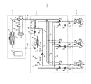
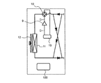
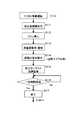
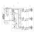
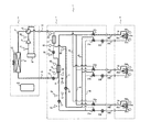
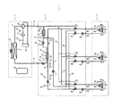
図1は本発明の実施の形態に係る空気調和装置の構成を示す回路図である。図2は本発明の実施の形態に係る空気調和装置の冷房運転のみの場合の動作を示す回路図である。図3は本発明の実施の形態に係る空気調和装置の冷房主体運転の場合の動作を示す回路図である。図4は本発明の実施の形態に係る空気調和装置の他の実施例の要部を示す回路図である。図5は本発明の実施の形態に係る空気調和装置の更に他の実施例の要部を示す回路図である。図6は本発明の実施の形態に係る空気調和装置の通常運転時の動作を示すフローチャートである。図7は本発明の実施の形態に係る空気調和装置のデフロスト準備運転時の動作を示すフローチャートである。図8は本発明の実施の形態に係る空気調和装置のデフロスト運転時の動作を示すフローチャートである。図9は本発明の実施の形態に係る空気調和装置のデフロスト前の動作を示す回路図である。図10は本発明の実施の形態に係る空気調和装置のデフロスト準備運転の動作を示す回路図である。図11は本発明の実施の形態に係る空気調和装置のデフロスト運転の動作を示す回路図である。なお、前述の図2,3,9〜11において、開放されている管は太線(実線)、閉じられている管は細線(実線)で示す。 FIG. 1 is a circuit diagram showing a configuration of an air-conditioning apparatus according to an embodiment of the present invention. FIG. 2 is a circuit diagram showing an operation in the case of only the cooling operation of the air-conditioning apparatus according to the embodiment of the present invention. FIG. 3 is a circuit diagram showing an operation in the cooling main operation of the air-conditioning apparatus according to the embodiment of the present invention. FIG. 4 is a circuit diagram showing a main part of another example of the air-conditioning apparatus according to the embodiment of the present invention. FIG. 5 is a circuit diagram showing a main part of still another example of the air-conditioning apparatus according to the embodiment of the present invention. FIG. 6 is a flowchart showing an operation during normal operation of the air-conditioning apparatus according to the embodiment of the present invention. FIG. 7 is a flowchart showing an operation during the defrost preparation operation of the air-conditioning apparatus according to the embodiment of the present invention. FIG. 8 is a flowchart showing an operation at the time of defrosting operation of the air-conditioning apparatus according to the embodiment of the present invention. FIG. 9 is a circuit diagram showing an operation before defrosting of the air-conditioning apparatus according to the embodiment of the present invention. FIG. 10 is a circuit diagram showing the operation of the defrost preparation operation of the air-conditioning apparatus according to the embodiment of the present invention. FIG. 11 is a circuit diagram showing the operation of the defrost operation of the air-conditioning apparatus according to the embodiment of the present invention. In FIGS. 2, 3, and 9 to 11 described above, the open pipe is indicated by a thick line (solid line), and the closed pipe is indicated by a thin line (solid line).
本実施の形態の空気調和装置1は、図1に示すように、熱源ユニット2、中継ユニット3、負荷ユニット4から構成される。熱源ユニット2は、建物の屋上、屋外、地下などの機械室に設けられる。負荷ユニット4は、居室、または居室近傍に設けられる。中継ユニットは、熱源ユニット2に隣接して設けてもよいし、居室の近傍に設けてもよい。
As shown in FIG. 1, the
また、空気調和装置1は、第1の媒体が循環する第1のサイクル5、第2の媒体が循環する第2のサイクル6、第2の媒体が循環する第3のサイクル7、から構成される。第1の媒体はフロン系冷媒のみならず、自然冷媒、第2の媒体は水または水に防腐剤などの添加物を加えたもの、あるいはブラインである。
The
第1のサイクル5は、圧縮機9、四方弁10、第1の熱交換器11、それに付随する室外機ファン12、第1の延長配管13、第1の減圧弁14、第2の熱交換器15、第2の減圧弁16、第3の熱交換器17、第2の延長配管18、前記四方弁10、アキュームレーター19、前記圧縮機9、と順に接続されて構成される。
The
第2のサイクル6は、第2の熱交換器15、第1のポンプ21、第1の分岐路40、複数の分岐経路8a〜8c、第1の集約路41、前記第2の熱交換器15、を順に接続して構成される。
The second cycle 6 includes a
第3のサイクル7は、第3の熱交換器17、第2のポンプ22、第2の分岐路42、複数の分岐経路8a〜8c、第2の集約路43、前記第3の熱交換器17、を順に接続して構成される。
The
複数の分岐経路8a〜8cは、第1の流路切替弁31a〜31c、流量調整弁32a〜32c、第3の延長配管33a〜33c、室内機34a〜34c、それに付随する室内機ファン35a〜35c、第4の延長配管36a〜36c、第2の流路切替弁37a〜37c、から構成される。
The plurality of
次に、本実施の形態の空気調和装置の動作(各種運転モード)について説明する。 Next, the operation (various operation modes) of the air conditioner of the present embodiment will be described.
冷房運転モード
まず、冷房運転のみの場合について図2を用いて説明する。
この空気調和装置1では、四方弁10が実線で示すように接続されており、圧縮機9で高圧高温に圧縮された第1の媒体は、四方弁10を通過して、第1の熱交換器11に入り、室外機ファン12により供給される外気に放熱することにより、第1の媒体は高圧低温となる。次いで、第1の延長配管13を通過し、第1の減圧弁14で減圧され、第1の媒体は低圧低乾き度となる。次に、第2の熱交換器15、第2の減圧弁16、第3の熱交換器17を通過する。第2の減圧弁16は全開であり、圧力損失は小さい。第2の熱交換器15は第1のサイクル5と第2のサイクル6間で熱交換し、第3の熱交換器17は第1のサイクル5と第3のサイクル7間で熱交換し、冷熱を第2の媒体に供給することで第1の媒体は蒸発し、低圧高乾き度、あるいは低圧過熱ガスとなる。第2の延長配管18、四方弁10、アキュームレーター19を通過し、再び圧縮機9へ循環される。 Cooling Operation Mode First, the case of only the cooling operation will be described with reference to FIG.
In this
ここで、制御装置100は以下の働きをする。すなわち、制御装置100は、圧力センサー51で検出される圧力が一定となるように圧縮機9の回転数を制御するとともに、圧力センサー52で検出される圧力が一定となるように第1の熱交換器11の室外機ファン12等により第1の熱交換器11の処理能力を制御する。また、ここでは第2の減圧弁16が全開である。したがって、制御装置100は、下式(1)により求められる第3の熱交換器17の出口スーパーヒート
(出口スーパーヒート)=(温度センサー64の検知値)−(圧力センサー51の飽和温度換算値)‥‥‥‥‥‥‥‥‥‥‥‥‥‥‥‥‥‥‥‥‥‥‥‥‥‥‥‥‥‥‥(1)
が一定となるように第1の減圧弁14の開度を制御する。これにより、室内機34a〜34cの運転台数に応じて適切な冷房能力が実現できる。Here, the
Is controlled so that the opening of the first pressure reducing valve 14 is constant. Thereby, suitable cooling capacity is realizable according to the number of operation of
また、流量調整弁32a〜32cの開度は、下式(2)により求められるそれぞれが対応する室内機34a〜34cの出入口温度差
(出入口温度差)=(温度センサー67の検知値)−(温度センサー68の検知値)‥‥‥‥‥‥‥‥‥‥‥‥‥‥‥‥‥‥‥‥‥‥‥‥‥‥‥‥‥‥‥‥‥‥‥‥‥‥(2)
が一定となるように制御される。In addition, the opening degree of the flow
Is controlled to be constant.
第1のポンプ21の回転数は、下式(3)により求められる第1の圧力差
(第1の圧力差)=(圧力センサー55の検知値)−(圧力センサー54の検知値)‥‥‥‥‥‥‥‥‥‥‥‥‥‥‥‥‥‥‥‥‥‥‥‥‥‥‥‥‥‥‥‥‥‥‥‥‥‥(3)
が一定となるように制御される。The number of rotations of the
Is controlled to be constant.
第2のポンプ22の回転数は、下式(4)により求められる第2の圧力差
(第2の圧力差)=(圧力センサー57の検知値)−(圧力センサー56の検知値)‥‥‥‥‥‥‥‥‥‥‥‥‥‥‥‥‥‥‥‥‥‥‥‥‥‥‥‥‥‥‥‥‥‥‥‥‥‥(4)
が一定となるように制御される。
これにより、各室内機34a〜34cに第2の媒体を適切に循環させることができる。The number of rotations of the
Is controlled to be constant.
Thereby, a 2nd medium can be appropriately circulated through each
第2の熱交換器15で第1のサイクル5より冷熱を供給された第2のサイクル6は、第2の媒体が低温であり、第2の媒体が第1のポンプ21によって循環され、第1の流路切替弁31a、31bにより分岐経路8a、8bに至る。流量調整弁32a,32bで当該流量調整弁の抵抗の程度(開度)により、分岐経路8a、8bを通過する第2の媒体の流量が定まる。第2の媒体は、第3の延長配管33a、33bを通過し、室内機34a、34bに至る。そして、第2の媒体は、室内機ファン35a、35bにより居室の空気と熱交換させることで、冷熱を負荷側へ供給し、高温となる。また、この高温となった第2の媒体は、さらに第4の延長配管36a,36bを通過し、第2の流路切替弁37a,37bを通過した後、第1の集約路41で集約され、再び第2の熱交換器15に至る。
In the second cycle 6 in which the cold heat is supplied from the
一方、第3の熱交換器17で第1のサイクル5より冷熱を供給された第3のサイクル7は、第2の媒体が低温であり、第2の媒体が第2のポンプ22によって循環され、第2の分岐路42から第1の流路切替弁31cにより分岐経路8cに至る。流量調整弁32cで当該流量調整弁の抵抗の程度(開度)により、分岐経路8cを通過する第2の媒体の流量が定まる。第2の媒体は、第3の延長配管33cを通過し、室内機34cに至る。そして、第2の媒体は、室内機ファン35cにより居室の空気と熱交換させることで、冷熱を負荷側へ供給し、高温となる。また、この高温となった第2の媒体は、第4の延長配管36cを通過し、第2の流路切替弁37cを通過した後、再び第3の熱交換器17に至る。
On the other hand, in the
停止している室内機があれば、この停止している室内機側の流量調整弁が全閉であるか、この停止している室内機側の流路切替弁が第2のサイクル6、第3のサイクル7のどちらにも導通していないことを意味する。
If there is a stopped indoor unit, the flow control valve on the stopped indoor unit side is fully closed, or the stopped indoor unit side flow path switching valve is connected to the second cycle 6, This means that it is not conducting to either
冷房運転モード(要求温度が異なる場合)
次に、冷房運転のみで、要求される温度が異なる場合について図2を用いて説明する。
この空気調和装置1では、四方弁10が実線で示すように接続されており、圧縮機9で高圧高温に圧縮された第1の媒体は、四方弁10を通過して、第1の熱交換器11に入り、室外機ファン12により供給される外気に放熱することにより、高圧低温となる。次いで、第1の媒体は、第1の延長配管13を通過し、第1の減圧弁14で減圧され、低圧低乾き度となる。次に、第1の媒体は、第2の熱交換器15、第2の減圧弁16、第3の熱交換器17を通過する。第2の減圧弁16では圧力低下が生じ、通過前後の圧力の飽和温度換算値が、要求される温度に対応する。第2の熱交換器15は、第1のサイクル5と第2のサイクル6間で熱交換し、第3の熱交換器17は、第1のサイクル5と第3のサイクル7間で熱交換し、冷熱を第2の媒体に供給することで、第1の媒体は蒸発し、低圧高乾き度、あるいは低圧過熱ガスとなる。そして、第1の媒体は、第2の延長配管18、四方弁10、アキュームレーター19を通過し、再び圧縮機9へ循環される。 Cooling operation mode (when required temperature is different)
Next, the case where the required temperature differs only by the cooling operation will be described with reference to FIG.
In this
ここで、制御装置100は以下の働きをする。すなわち、制御装置100は、圧力センサー51で検出される圧力が一定となるように圧縮機9の回転数を制御するとともに、圧力センサー52で検出される圧力が一定となるように室外機ファン12等により第1の熱交換器11の処理能力を制御する。また、制御装置100は、ここでも前記(1)式により求められる第3の熱交換器17の出口スーパーヒートが一定となるように第1の減圧弁14の開度を制御する。
Here, the
また、第2の減圧弁16の開度は、下式(5)により求められる温度差
(温度差)=(圧力センサー53の飽和温度換算値)−(圧力センサー51の飽和温度換算値)‥‥‥‥‥‥‥‥‥‥‥‥‥‥‥‥‥‥‥‥‥‥‥‥‥‥‥‥‥‥‥‥‥(5)
が要求される温度差となるように制御される。これにより、室内機の運転台数に応じて適切な冷房能力が実現できる。Further, the opening of the second pressure reducing valve 16 is calculated by the following equation (5): temperature difference (temperature difference) = (saturated temperature converted value of pressure sensor 53) − (saturated temperature converted value of pressure sensor 51). ……………………………………………………………………………………………………………………………………………………………… (5)
Is controlled to achieve the required temperature difference. Thereby, appropriate cooling capacity can be realized according to the number of indoor units operated.
第2の熱交換器15で第1のサイクル5より冷熱を供給された第2のサイクル6は、第2の減圧弁16で圧力低下する以前の圧力下の第1媒体より冷熱の供給を受けるため、蒸発温度が第3のサイクルより高く、室内機の吹出し温度が高い。
The second cycle 6 supplied with cold from the
一方、第3の熱交換器17で第1のサイクル5より冷熱を供給された第3のサイクル7は、第2の減圧弁16で圧力低下した後の圧力下の第1媒体より冷熱の供給を受けるため、蒸発温度が第2のサイクル6より低く、室内機の吹出し温度が低い。
On the other hand, in the
ここで、制御装置100は以下の働きをする。すなわち、制御装置100は、ここでも前記(2)式により求められる出入口温度差が一定となるように、流量調整弁32a〜32cの開度を制御する。
Here, the
また、制御装置100は、ここでも前記(3)式により求められる第1の圧力差が一定となるように、第1のポンプ21の回転数を制御する。
In addition, the
また、制御装置100は、ここでも前記(4)式により求められる第2の圧力差が一定となるように、第2のポンプ22の回転数を制御する。
これにより各室内機34a〜34cに第2の媒体を適切に循環させることができる。In addition, the
Thereby, a 2nd medium can be appropriately circulated through each
ここでも、停止している室内機があれば、この停止している室内機側の流量調整弁が全閉であるか、この停止している室内機側の流路切替弁が第2のサイクル6、第3のサイクル7のどちらにも導通していないことを意味する。
Again, if there is a stopped indoor unit, the flow control valve on the stopped indoor unit side is fully closed, or the stopped indoor unit side flow path switching valve is in the second cycle. 6 and the
冷暖房同時運転モード(冷房主体運転の場合)
次に、冷房と暖房を同時に行い、冷房能力が暖房能力より大きい場合(冷房主体運転)について図3を用いて説明する。
この空気調和装置1では、四方弁10は実線で示すように接続されており、圧縮機9で高圧高温に圧縮された第1の媒体は、四方弁10を通過して、第1の熱交換器11に入り、室外機ファン12により供給される外気に放熱することにより、第1の媒体は臨界圧力以上の場合は高圧中温となる。次いで、第1の媒体は、第1の延長配管13、第1の減圧弁14を通過し、第2の熱交換器15を通過する。ここで、第1の減圧弁14は全開である。第2の熱交換器15は、第1のサイクル5と第2のサイクル6間で熱交換し、温熱を第2の媒体に供給する。これにより、第1の媒体は高圧低温となる。次いで、第1の媒体は、第2の減圧弁16を通過し、低圧低乾き度となる。第3の熱交換器17は、第1のサイクル5と第3のサイクル7間で熱交換し、冷熱を第2の媒体に供給する。これにより、第1の媒体は蒸発し、低圧高乾き度、あるいは低圧過熱ガスとなる。そして、第1の媒体は、第2の延長配管18、四方弁10、アキュームレーター19を通過し、再び圧縮機9へ循環される。 Air-conditioning simultaneous operation mode (in the case of cooling-based operation)
Next, a case where cooling and heating are performed simultaneously and the cooling capacity is larger than the heating capacity (cooling main operation) will be described with reference to FIG.
In this
ここで、制御装置100は、以下の働きをする。すなわち、制御装置100は、圧力センサー51で検出される圧力が一定となるように圧縮機9の回転数を制御するとともに、圧力センサー52で検出される圧力が一定となるように室外機ファン12等により第1の熱交換器11の処理能力を制御する。また、ここでは第1の減圧弁14の開度が全開である。したがって、制御装置100は、下式(6)により求められる第3の熱交換器17の出口スーパーヒート
(出口スーパーヒート)=(温度センサー64の検知値)−(圧力センサー51の飽和温度換算値)‥‥‥‥‥‥‥‥‥‥‥‥‥‥‥‥‥‥‥‥‥‥‥‥‥‥‥‥‥‥‥(6)
が一定となるように第2の減圧弁16の開度を制御する。これにより、室内機34a〜34cの運転台数に応じて適切な冷房能力と暖房能力が実現できる。Here, the
The opening degree of the second pressure reducing valve 16 is controlled so that becomes constant. Thereby, appropriate cooling capability and heating capability can be realized according to the number of operating
第2の熱交換器15で第1のサイクル5より温熱を供給された第2のサイクル6は、第2の媒体が高温であり、第2の媒体が第1のポンプ21によって循環され、第1の流路切替弁31aにより分岐経路8aに至る。流量調整弁32aで当該流量調整弁の抵抗の程度(開度)により、分岐経路8aを通過する第2の媒体の流量が定まる。第2の媒体は、第3の延長配管33aを通過し、室内機34aに至る。そして、第2の媒体は、室内機ファン35aにより居室の空気と熱交換させることで、冷熱を負荷側へ供給し、低温となる。また、この低温となった第2の媒体は、第4の延長配管36aを通過し、第2の流路切替弁37aを通過した後、第1の集約路41を通過し、再び第2の熱交換器15に至る。
In the second cycle 6 in which the heat is supplied from the
一方、第3の熱交換器17で第1のサイクル5より冷熱を供給された第3のサイクル7は、第2の媒体が低温であり、第2の媒体が第2のポンプ22によって循環され、第2の分岐路42から第1の流路切替弁31b、31cにより分岐経路8b、8cに至る。流量調整弁32b、32cで当該流量調整弁の抵抗の程度(開度)により、分岐経路8b、8cを通過する第2の媒体の流量が定まる。第2の媒体は、第3の延長配管33b、33cを通過し、室内機34b、34cに至る。そして、第2の媒体は、室内機ファン35b、35cにより居室の空気と熱交換させることで、冷熱を負荷側へ供給し、高温となる。また、この高温となった第2の媒体は、第4の延長配管36b、36cを通過し、第2の流路切替弁37b、37cを通過した後、第2の集約路43で集約され、再び第3の熱交換器17に至る。
On the other hand, in the
暖房運転モード
次に、暖房運転のみの場合について前記図2を用いて説明する。
この空気調和装置1では、四方弁10は破線で示すように接続されており、圧縮機9で高圧高温に圧縮された第1の媒体は、四方弁10を通過して、第2の延長配管18、第3の熱交換器17、第2の減圧弁16、第2の熱交換器15を通過する。第2の減圧弁16は全開であり、圧力損失は小さい。第1の媒体は、第3の熱交換器17、第2の熱交換器15を通過する際に、第3のサイクル7、第2のサイクル6と熱交換することにより、高圧低温となる。次いで、第1の媒体は、第1の減圧弁14を通過して、低圧低乾き度となる。次に、第1の媒体は、第1の延長配管13を通過し、第1の熱交換器11に入り、室外機ファン12により供給される外気より吸熱することにより、低圧高乾き度となる。その後、第1の媒体は、四方弁10、アキュームレーター19を通過して再び圧縮機9に循環される。既述したように、ビル用の空調機は、熱交換器の大きさ、延長配管と減圧弁の配置の仕方により、冷房よりも暖房時に余剰冷媒が生じるため、これをアキュームレーター19に収納し、圧縮機9に液冷媒が吸入されることを防ぎ、信頼性を確保する。 Heating operation mode Next, the case of only the heating operation will be described with reference to FIG.
In this
ここで、制御装置100は以下の働きをする。すなわち、制御装置100は、圧力センサー52で検出される圧力が一定となるように圧縮機9の回転数を制御するとともに、圧力センサー51で検出される圧力が一定となるように室外機ファン12等により第1の熱交換器11の処理能力を制御する。また、ここでは第2の減圧弁16が全開である。したがって、制御装置100は、下式(7)により求められる第2の熱交換器15の(出口サブクール
(出口サブクール)=(圧力センサー52の飽和温度換算値)−(温度センサー61の検知値)‥‥‥‥‥‥‥‥‥‥‥‥‥‥‥‥‥‥‥‥‥‥‥‥‥‥‥‥‥‥‥‥‥(7)
が一定となるように第1の減圧弁14の開度を制御する。これにより、室内機34a〜34cの運転台数に応じて適切な暖房能力が実現できる。Here, the
Is controlled so that the opening of the first pressure reducing valve 14 is constant. Thereby, appropriate heating capacity is realizable according to the number of operation of
また、第3の熱交換器17で第1のサイクル5より温熱を供給された第3のサイクル7は、第2の媒体が高温であり、第2の媒体が第2のポンプ22によって循環され、第1の流路切替弁31cにより分岐経路8cに至る。流量調整弁32cで当該流量調整弁の抵抗の程度(開度)により、分岐経路8cを通過する第2の媒体の流量が定まる。第2の媒体は、第3の延長配管33cを通過し、室内機34cに至る。そして、第2の媒体は、室内機ファン35cにより居室の空気と熱交換させることで、温熱を負荷側へ供給し、低温となる。また、この低温となった第2の媒体は、第4の延長配管36cを通過し、第2の流路切替弁37cを通過した後、再び第3の熱交換器17に至る。
Further, in the
一方、第2の熱交換器15で第1のサイクル5より温熱を供給された第2のサイクル6は、第2の媒体が高温であり、第2の媒体が第1のポンプ21によって循環され、第1の流路切替弁31a、31bにより分岐経路8a、8bに至る。流量調整弁32a,32bで当該流量調整弁の抵抗の程度(開度)により、分岐経路8a、8bを通過する第2の媒体の流量が定まる。第2の媒体は、第3の延長配管33a、33bを通過し、室内機34a、34bに至る。そして、第2の媒体は、室内機ファン35a、35bにより居室の空気と熱交換させることで、温熱を負荷側へ供給し、低温となる。また、この低温となった第2の媒体は、第4の延長配管36a,36bを通過し、第2の流路切替弁37a,37bを通過した後、第1の集約路41で集約され、再び第2の熱交換器15に至る。
On the other hand, in the second cycle 6 in which the heat is supplied from the
ここで、制御装置100は、以下の働きをする。すなわち、制御装置100は、流量調整弁32a〜32cの開度を、前記(2)式により求められる室内機34a〜34cの出入口温度差が一定となるよう制御する。また、制御装置100は、第1のポンプ21の回転数を、前記(3)式により求められる第1の圧力差が一定となるよう制御する。更に、制御装置100は、第2のポンプ22の回転数を、前記(4)式により求められる第2の圧力差が一定となるよう制御する。
これにより各室内機34a〜34cに第2の媒体を適切に循環させることができる。Here, the
Thereby, a 2nd medium can be appropriately circulated through each
ここでも、停止している室内機があれば、この停止している室内機側の流量調整弁が全閉であるか、この停止している室内機側の流路切替弁が第2のサイクル6、第3のサイクル7のどちらにも導通していないことを意味する。
Again, if there is a stopped indoor unit, the flow control valve on the stopped indoor unit side is fully closed, or the stopped indoor unit side flow path switching valve is in the second cycle. 6 and the
暖房運転モード(要求温度が異なる場合)
次に、暖房運転のみで、要求される温度が異なる場合について前記図3を用いて説明する。
この空気調和装置1では、四方弁10は破線で接続されており、圧縮機9で高圧高温に圧縮された第1の媒体は、四方弁10を通過して、第2の延長配管18を通過し、第3の熱交換器17、第2の減圧弁16、第2の熱交換器15を通過する。第2の減圧弁16では圧力低下が生じ、通過前後の圧力の飽和温度換算値が、要求される温度に対応する。第1の媒体は、第3の熱交換器17、第2の熱交換器15を通過する際に第3のサイクル7、第2のサイクル6と熱交換することにより、高圧低温となる。次いで、第1の媒体は、第1の減圧弁14を通過して、低圧低乾き度となる。次に、第1の媒体は、第1の延長配管13を通過し、第1の熱交換器11に入り、室外機ファン12により供給される外気より吸熱することにより、低圧高乾き度となる。その後、第1の媒体は、四方弁10、アキュームレーター19を通過して再び圧縮機9に循環される。既述したように一般的に、ビル用の空調機は、熱交換器の大きさ、延長配管と減圧弁の配置の仕方により、冷房よりも暖房時に余剰冷媒が生じる。このため、ここでも暖房時の余剰冷媒をアキュームレーター19に収納し、圧縮機9に液冷媒が吸入されることを防ぎ、信頼性を確保する。 Heating operation mode (when required temperature is different)
Next, the case where the required temperature differs only in the heating operation will be described with reference to FIG.
In this
ここで、制御装置100は以下の働きをする。すなわち、制御装置100は、圧力センサー52で検出される圧力が一定となるように圧縮機9の回転数を制御するとともに、圧力センサー51で検出される圧力が一定となるように室外機ファン12等により第1の熱交換器11の処理能力を制御する。また、制御装置100は、下式(8)により求められる温度差
(温度差)=(圧力センサー52の飽和温度換算値)−(圧力センサー53の飽和温度換算値)‥‥‥‥‥‥‥‥‥‥‥‥‥‥‥‥‥‥‥‥‥‥‥‥‥‥‥‥‥‥‥‥‥(8)
が要求される温度差となるように第2の減圧弁16の開度を制御する。Here, the
The degree of opening of the second pressure reducing valve 16 is controlled so that the required temperature difference is obtained.
また、制御装置100は、第1の減圧弁14の開度を、前記(7)式により求められる第2の熱交換器15の出口サブクールが一定となるよう制御する。これにより、室内機34a〜34cの運転台数に応じて適切な暖房能力が実現できる。
Moreover, the
また、第3の熱交換器17で第1のサイクル5より温熱を供給された第3のサイクル7は、第2の減圧弁16で圧力低下する前の圧力下にある第1の媒体から温熱を供給されるので、第2の媒体の温度が第2のサイクルよりも高く、室内機の吹出し温度が高い。
Further, the
一方、第2の熱交換器15で第1のサイクル5より温熱を供給された第2のサイクル6は、第2の減圧弁16で圧力低下した後の圧力下にある第1の媒体から温熱を供給されるので、第2の媒体蒸発温度が第3のサイクル7より低く、室内機の吹出し温度が低い。
On the other hand, the second cycle 6 supplied with warm heat from the
ここで、制御装置100は、以下の働きをする。すなわち、制御装置100は、流量調整弁32a〜32cの開度を、前記(2)式により求められる室内機34a〜34cの出入口温度差が一定となるよう制御する。また、制御装置100は、第1のポンプ21の回転数を、前記(3)式により求められる第1の圧力差が一定となるよう制御する。更に、制御装置100は、第2のポンプ22の回転数を、前記(4)式により求められる第2の圧力差が一定となるよう制御する。これにより各室内機に媒体2を適切に循環させることができる。
Here, the
ここでも、停止している室内機があれば、この停止している室内機側の流量調整弁が全閉であるか、この停止している室内機側の流路切替弁が第2のサイクル6、第3のサイクル7のどちらにも導通していないことを意味する。
Again, if there is a stopped indoor unit, the flow control valve on the stopped indoor unit side is fully closed, or the stopped indoor unit side flow path switching valve is in the second cycle. 6 and the
冷暖房同時運転モード(暖房主体運転の場合)
次に、冷房と暖房を同時に行い、暖房能力が冷房能力より大きい場合(暖房主体運転)について図3を用いて説明する。
この空気調和装置1では、四方弁10は破線で示すように接続されており、圧縮機9で高圧高温に圧縮された第1の媒体は、四方弁10を通過して、第2の延長配管18、第3の熱交換器17を通過する。第1の媒体は、第3の熱交換器17を通過する際に、第3のサイクル7と熱交換することにより、高圧低温となる。次いで、第1の媒体は、第2の減圧弁16で減圧され、低圧低乾き度となる。次に、第1の媒体は、第2の熱交換器15を通過する。その際、第1の媒体は、第2のサイクル6と熱交換することにより、低圧低乾き度となる。次いで、第1の媒体は、全開された第1の減圧弁14を通過し、第1の延長配管13を通過し、第1の熱交換器11に入り、室外機ファン12により供給される外気より吸熱することにより、低圧二相となる。その後、第1の媒体は、四方弁10、アキュームレーター19を通過して再び圧縮機9に循環される。既述したように、ビル用の空調機は、熱交換器の大きさ、延長配管と減圧弁の配置の仕方により、冷房よりも暖房時に余剰冷媒が生じるため、これをアキュームレーター19に収納し、圧縮機9に液冷媒が吸入されることを防ぎ、信頼性を確保する。 Air-conditioning simultaneous operation mode (in the case of heating-based operation)
Next, a case where cooling and heating are performed simultaneously and the heating capacity is larger than the cooling capacity (heating main operation) will be described with reference to FIG.
In this
ここで、制御装置100は以下の働きをする。すなわち、制御装置100は、圧力センサー52で検出される圧力が一定となるように圧縮機9の回転数を制御するとともに、圧力センサー51で検出される圧力が一定となるように室外機ファン12等により第1の熱交換器11の処理能力を制御する。また、ここでは第1の減圧弁14の開度が全開である。したがって、制御装置100は、下式(9)により求められる第3の熱交換器17の出口サブクール
(出口サブクール)=(圧力センサー52の飽和温度換算値)−(温度センサー63の検知値)‥‥‥‥‥‥‥‥‥‥‥‥‥‥‥‥‥‥‥‥‥‥‥‥‥‥‥‥‥‥‥‥‥(9)
が一定となるように第2の減圧弁16の開度を制御する。これにより室内機34a〜34cの運転台数に応じて適切な冷房能力と暖房能力が実現できる。Here, the
The opening degree of the second pressure reducing valve 16 is controlled so that becomes constant. Thereby, appropriate cooling capability and heating capability can be realized according to the number of operating
また、第3の熱交換器17で第1のサイクル5より温熱を供給された第3のサイクル7は、第2の媒体が高温であり、第2の媒体が第2のポンプ22によって循環され、第1の流路切替弁31b、31cにより分岐経路8b、8cに至る。流量調整弁32b、32cで当該流量調整弁の抵抗の程度(開度)により、分岐経路8b、8cを通過する第2の媒体の流量が定まる。第2の媒体は、第3の延長配管33b、33cを通過し、室内機34b、34cに至る。そして、第2の媒体は、室内機ファン35b、35cにより居室の空気と熱交換させることで、温熱を負荷側へ供給し、低温となる。また、この低温となった第2の媒体は、第4の延長配管36b、36cを通過し、第2の流路切替弁37b、37cを通過した後、第2の集約路43で集約され、再び第3の熱交換器17に至る。
Further, in the
一方、第2の熱交換器15で第1のサイクル5より冷熱を供給された第2のサイクル6は、第2の媒体が低温であり、第2の媒体が第1のポンプ21によって循環され、第1の流路切替弁31aを通過により分岐経路8aに至る。流量調整弁32aで当該流量調整弁の抵抗の程度(開度)により、分岐経路8aを通過する第2の媒体の流量が定まる。第2の媒体は、第3の延長配管33aを通過し、室内機34aに至る。そして、第2の媒体は、室内機ファン35aにより居室の空気と熱交換させることで、冷熱を負荷側へ供給し、第2の媒体は高温となる。また、この高温となった第2の媒体は、第4の延長配管36aを通過し、第2の流路切替弁37aを通過した後、第1の集約路41を通過して、再び第2の熱交換器15に至る。
On the other hand, in the second cycle 6 in which the cold heat is supplied from the
ここで、制御装置100は以下の働きをする。すなわち、制御装置100は、ここでも前記(2)式により求められる出入口温度差が一定となるように流量調整弁32a〜32cの開度を制御する。
Here, the
また、制御装置100は、ここでも前記(3)式により求められる第1の圧力差が一定となるように第1のポンプ21の回転数を制御する。
In addition, the
また、制御装置100は、ここでも前記(4)式により求められる第2の圧力差が一定となるように、第2のポンプ22の回転数を制御する。
これにより各室内機34a〜34cに第2の媒体を適切に循環させることができる。In addition, the
Thereby, a 2nd medium can be appropriately circulated through each
これらの動作により、冷房のみ、暖房のみ、冷房と暖房混在運転(冷暖房同時運転)を効率よく実現することができる。 By these operations, it is possible to efficiently realize only cooling, heating only, and cooling and heating mixed operation (simultaneous cooling and heating operation).
なお、第1の減圧弁14は、開度を調整することができるが、並列に開閉弁を設けて減圧弁が全開の場合は、開閉弁を開、減圧弁が全開でない場合は、開閉弁を閉として、減圧弁が全開の場合の圧損低下を低減させてもよい。 The opening of the first pressure reducing valve 14 can be adjusted. However, when the pressure reducing valve is fully open by providing an opening / closing valve in parallel, the opening / closing valve is opened. When the pressure reducing valve is not fully open, the opening / closing valve is opened. May be closed to reduce a decrease in pressure loss when the pressure reducing valve is fully open.
また、第2の熱交換器15、第3の熱交換器17は、プレート熱交換器、2重管熱交換器、マイクロチャンネル熱交換器、のいずれであってもよい。ただし、プレート熱交換器のように流れ方向に制約がある場合は、切り替え弁などを設けてもよい。
Further, the
また、室外ユニットと中継ユニットのいずれかで、図4に示すようなブリッジ回路を設けてもよい。これにより、運転中に四方弁を正逆切替えても、冷媒音等を抑制でき、第1の媒体の制御安定性が保たれる。 Moreover, you may provide a bridge circuit as shown in FIG. 4 in either an outdoor unit or a relay unit. Thereby, even if the four-way valve is switched between forward and reverse during operation, the refrigerant noise and the like can be suppressed, and the control stability of the first medium is maintained.
また、第1の熱交換器11の処理能力を、室外機ファン12の回転速度を変化させることで制御する以外に、図5に示すように、第1の熱交換器を並列に分割し、分割の程度で処理能力を変化させても良い。室外機ファン12が1個である場合や、ファンモータ信頼性上回転数を低下できない場合に有効である。
In addition to controlling the processing capacity of the
次に、空気熱交換器である第1の熱交換器をデフロストするときの動作について図6のフローチャートに基づき図9を参照しながら説明する。空気調和装置1がステップS101で起動されると、ステップS102で初期設定が行われ、ステップS103で起動し、ステップS104で定常運転となる。ステップS105で運転がデフロスト運転が必要かどうか判断する。第1の熱交換器11が第1の媒体に対して放熱器として機能する場合は、デフロスト運転は必要ない。第1の熱交換器11が第1の媒体に対して蒸発器として機能する場合は、デフロスト運転が必要なため、ステップS106へ進む。ステップS106はデフロスト運転を開始するかどうかを判断する。判断基準は、外気温度、暖房負荷、第1の熱交換器11の温度、連続運転時間を参考にして、第1の熱交換器11の表面に着霜したか否かを判断する。ステップS106で着霜していないと判断された場合は、再度着霜判断を行う。また、ステップS106で着霜してると判断された場合は、ステップS107でデフロスト準備運転、ステップS108でデフロスト運転を行い、ステップS105へ戻る。
Next, the operation when defrosting the first heat exchanger which is an air heat exchanger will be described with reference to FIG. 9 based on the flowchart of FIG. When the
次に、デフロスト準備運転の動作について図7のフローチャートに基づき図10を参照しながら説明する。ステップS110でデフロスト準備運転が開始されると、ステップS111で定常運転時に停止していた空調機(室内機)を判別する。以下については停止していた空調機のみが対象である。ステップS112で室内機ファンを停止し、ステップS113で該当する流量調整弁の開度を、全閉から開ける。ステップS114で流路切替弁を第3のサイクル7に導通する。ステップS115で第1のサイクル5での圧力センサー52の目標値を増加させることで圧縮機周波数を増加させる。ステップS116で一定時間経過するとステップS117で終了し、ステップS120のデフロスト運転へ進む。停止していた空調機(室内機)、第3の延長配管、第4の延長配管に加熱された第2の媒体が行き渡ればよいので、ステップS113での開度、ステップS116での一定時間はそれほど大きくする必要はない。
Next, the operation of the defrost preparation operation will be described with reference to FIG. 10 based on the flowchart of FIG. When the defrost preparation operation is started in step S110, the air conditioner (indoor unit) that has been stopped during the steady operation is determined in step S111. The following applies only to air conditioners that have been stopped. In step S112, the indoor unit fan is stopped, and in step S113, the opening of the corresponding flow rate adjustment valve is opened from the fully closed state. In step S114, the flow path switching valve is conducted to the
次に、デフロスト運転の動作について図8のフローチャートに基づき図11を参照しながら説明する。ステップS120でデフロスト運転が開始すると、ステップS122で第1サイクル5でデフロスト運転を行う。このときの回路構成は、冷房運転と同様である。四方弁10を切替え、圧縮機9を吐出した高温高圧の第1の媒体を第1の熱交換器11へ流すことにより、付着した霜を溶かして除去する。このとき、室内機ファンは停止させておくほうがよい。ステップS123で室内機を定常運転時に、暖房運転、冷房運転、停止のいずれかに分類する。定常時暖房運転していた室内機は、ステップS130で室内機ファンを停止し、ステップS131で流量調整弁の開度を開ける。ステップS132で流路切替弁を第3のサイクル7に導通する。
Next, the operation of the defrost operation will be described with reference to FIG. 11 based on the flowchart of FIG. When the defrost operation is started in step S120, the defrost operation is performed in the
また、ステップS123で定常運転時に冷房運転していた室内機は、ステップS140で通常運転のままの制御を行う。 Further, the indoor unit that has been in the cooling operation during the steady operation in step S123 performs the control in the normal operation in step S140.
また、ステップS123で定常運転時に停止していた室内機は、ステップS150で室内機ファンを停止し、ステップS151で該当する流量調整弁の開度を開ける。ステップS152で流路切替弁を第3のサイクル7に導通する。
Moreover, the indoor unit stopped at the time of steady operation in step S123 stops the indoor unit fan in step S150, and opens the opening of the corresponding flow rate adjustment valve in step S151. In step S152, the flow path switching valve is conducted to the
それぞれの空調機の操作が終了すると、ステップS160でデフロストの終了判断を行う。判断基準は、運転時間、第1の熱交換器11の温度を参考にして、第1の熱交換器11がデフロストできたか否かを判断する。ステップS160でデフロスト終了でないと判断された場合は、再度デフロストの終了判断を行う。また、ステップS160でデフロスト終了と判断された場合は、ステップS161で第1のサイクル5をデフロスト以前の運転モードに戻すため、四方弁10を切り替える。ステップS162で空調機を定常運転時に、暖房運転、冷房運転、停止のいずれかに分類する。つまり、定常運転時に暖房運転していた空調機は、ステップS171で流路切替弁を第3のサイクル7に導通し、ステップS172で流量調整弁の開度を温度差制御に戻し、ステップS173で室内機ファンを運転させる。
When the operation of each air conditioner is completed, the defrost end determination is performed in step S160. The determination criterion is to determine whether or not the
また、ステップS162で定常運転時に冷房運転していた空調機は、ステップS180で通常運転のままの制御を行う。 In addition, the air conditioner that has been in the cooling operation during the steady operation in step S162 performs the control in the normal operation in step S180.
また、ステップS162で定常運転時に停止していた空調機は、ステップS190で該当する流量調整弁の開度を全閉するとともに、ステップS191で室内機ファンを停止し、ステップS200でデフロスト運転を終了し、ステップS105へ戻る。 Further, the air conditioner that has been stopped during the steady operation in step S162 fully closes the opening of the corresponding flow rate adjustment valve in step S190, stops the indoor unit fan in step S191, and ends the defrost operation in step S200. Then, the process returns to step S105.
これら一連の動作の一例を示したのが前記図9、図10、図11であり、図9は暖房主体運転で、分岐経路8aが冷房運転、分岐経路8bが停止、分岐経路8cが暖房運転となっている状態、図10はデフロスト準備運転で、分岐経路8bが第3のサイクルに接続されるが室内機ファン35bが停止したままであり、分岐経路8b内の第2の媒体は循環するにつれ温度が上昇する状態、図11はデフロスト運転で四方弁が切り替えられ、分岐経路8bが第2のサイクル6に切り替えられ、分岐経路8cが第3のサイクル7に切り替えられ、更に第2のポンプが停止している状態を示している。
FIG. 9, FIG. 10 and FIG. 11 show an example of a series of these operations. FIG. 9 shows the heating-main operation, the
このように、第2の熱交換器15に暖められた分岐経路8bの第2の媒体が流入するため、第1の媒体は吸熱する。このため、除霜能力が増加する。また、分岐経路8c内の第2の媒体が循環されないため、デフロスト運転復帰後に、定常状態間で短時間で復帰できる。
Thus, since the 2nd medium of the
これらの動作により、圧縮機9の電気入力のみならず、熱源搬送手段である第2のサイクル6と第3のサイクル7に熱源を一時的に蓄えることで、デフロスト熱源として利用することができ、デフロスト時間を短縮することができる。デフロスト運転中に生じる熱は、第1の熱交換器11を除霜する以外に外気などの系外に流失するため、デフロスト時間が短縮されると、着想量が同じであっても効率のよい運転となる。
By these operations, the heat source is temporarily stored not only in the electric input of the compressor 9 but also in the second cycle 6 and the
1 空気調和装置、2 熱源ユニット、3 中継ユニット、4 負荷ユニット、5 第1のサイクル、6 第2のサイクル、7 第3のサイクル、8a〜8c 分岐経路、9 圧縮機、10 四方弁、11 第1の熱交換器、12 室外機ファン、13 第1の延長配管、14 第1の減圧弁、15 第2の熱交換器、16 第2の減圧弁、17 第3の熱交換器、18 第2の延長配管、19 アキュームレーター、21 第1のポンプ、22 第2のポンプ、31a〜31c 第1の流路切替弁、32a〜32c 流量調整弁、33a〜33c 第3の延長配管、34a〜34c 室内機、35a〜35e 室内機ファン、36a〜36c 第4の延長配管、37a〜37c 第2の流路切替弁、40 第1の分岐路、41 第1の集約路、42 第2の分岐路、43 第2の集約路、51、52、53、54、55、56、57 圧力センサー、61、62,63、64、65、66、67a〜67c、68a〜68c 温度センサー、100 制御装置。
DESCRIPTION OF
Claims (7)
第2の媒体が循環する第2のサイクルと、
第2の媒体が循環する第3のサイクルと、を備え、
前記第1のサイクルは、圧縮機と、空気熱交換器でなる第1の熱交換器と、第1の減圧弁と、第1のサイクルと第2のサイクルとの間で熱交換する第2の熱交換器と、第2の減圧弁と、第1のサイクルと第3のサイクルとの間で熱交換する第3の熱交換器と、第1の媒体の流れ方向を正逆に転換させる四方弁と、を順に接続してなり、
前記第2のサイクルは、前記第2の熱交換器と、前記第2の媒体を駆動させる第1のポンプと、1経路から複数に分岐する第1の分岐路と、ファンを有する室内機と、複数の経路から1経路に集約する第1の集約路と、を順に接続してなり、
前記第3のサイクルは、前記第3の熱交換器と、前記第2の媒体を駆動させる第2のポンプと、1経路から複数に分岐する第2の分岐路と、前記室内機と、複数の経路から1経路に集約する第2の集約路と、を順に接続してなり、
各前記分岐路の複数の経路側には、それぞれ前記第2のサイクルと前記第3のサイクルとの間で流路を切替接続できる第1の流路切替弁を設け、
各前記集約路の複数の経路側には、それぞれ前記第2のサイクルと前記第3のサイクルとの間で流路を切替接続できる第2の流路切替弁を設け、
前記室内機と組み合わされる一対の第1の流路切り替え弁と第2の流路切り替え弁は、第2のサイクルと第3のサイクルのいずれか一つの同じサイクルに切替接続し、第1の熱交換器を除霜する際に停止している室内機がある場合、停止している室内機側の前記第1と第2の流路切替弁を前記第3のサイクル側に切替し、第2のポンプを駆動させることを特徴とする空気調和装置。A first cycle in which the first medium circulates;
A second cycle in which the second medium circulates;
A third cycle in which the second medium circulates,
The first cycle includes a compressor, a first heat exchanger composed of an air heat exchanger, a first pressure reducing valve, and a second heat exchanger that exchanges heat between the first cycle and the second cycle. The heat exchanger, the second pressure reducing valve, the third heat exchanger for exchanging heat between the first cycle and the third cycle, and the flow direction of the first medium is changed in the forward and reverse directions. A four-way valve is connected in order,
The second cycle includes the second heat exchanger, a first pump that drives the second medium, a first branch path that branches from one path to a plurality of paths, and an indoor unit that includes a fan. A first aggregated route that aggregates a plurality of routes into one route in order,
The third cycle, the third heat exchanger, and a second pump to drive the second medium, and a second branch passage branched from first path into a plurality, and the chamber machine, A second aggregated route that aggregates a plurality of routes into one route in order,
Provided on the plurality of path sides of each of the branch paths is a first flow path switching valve that can switch and connect the flow path between the second cycle and the third cycle,
Provided on each of the plurality of route sides of each of the aggregated passages is a second flow path switching valve capable of switching the flow path between the second cycle and the third cycle,
The pair of the first flow path switching valve and the second flow path switching valve combined with the indoor unit are switched and connected to the same one of the second cycle and the third cycle, and the first heat When there is an indoor unit that is stopped when defrosting the exchanger, the first and second flow path switching valves on the stopped indoor unit side are switched to the third cycle side, and the second An air conditioner that drives a pump of the above.
Applications Claiming Priority (1)
| Application Number | Priority Date | Filing Date | Title |
|---|---|---|---|
| PCT/JP2009/058663 WO2010128551A1 (en) | 2009-05-08 | 2009-05-08 | Air conditioner |
Publications (2)
| Publication Number | Publication Date |
|---|---|
| JPWO2010128551A1 JPWO2010128551A1 (en) | 2012-11-01 |
| JP5172012B2 true JP5172012B2 (en) | 2013-03-27 |
Family
ID=43050064
Family Applications (1)
| Application Number | Title | Priority Date | Filing Date |
|---|---|---|---|
| JP2011512283A Active JP5172012B2 (en) | 2009-05-08 | 2009-05-08 | Air conditioner |
Country Status (5)
| Country | Link |
|---|---|
| US (1) | US8616017B2 (en) |
| EP (1) | EP2428741B1 (en) |
| JP (1) | JP5172012B2 (en) |
| CN (1) | CN102422091B (en) |
| WO (1) | WO2010128551A1 (en) |
Cited By (1)
| Publication number | Priority date | Publication date | Assignee | Title |
|---|---|---|---|---|
| JPWO2019193649A1 (en) * | 2018-04-03 | 2021-01-07 | 三菱電機株式会社 | Control unit, outdoor unit, heat source unit and air conditioning system |
Families Citing this family (26)
| Publication number | Priority date | Publication date | Assignee | Title |
|---|---|---|---|---|
| CN102422100B (en) * | 2009-05-13 | 2014-04-02 | 三菱电机株式会社 | Air conditioning apparatus |
| ES2752729T3 (en) * | 2010-12-09 | 2020-04-06 | Mitsubishi Electric Corp | Air conditioner |
| KR101712213B1 (en) * | 2011-04-22 | 2017-03-03 | 엘지전자 주식회사 | Multi type air conditiner and method of controlling the same |
| US9791194B2 (en) * | 2011-11-18 | 2017-10-17 | Mitsubishi Electric Corporation | Air-conditioning apparatus |
| FR2984471B1 (en) * | 2011-12-15 | 2013-11-29 | Valeo Systemes Thermiques | DEVICE FOR THERMALLY CONDITIONING A TRACTION CHAIN AND A VEHICLE HABITACLE |
| CN103874892B (en) * | 2011-12-16 | 2016-02-03 | 三菱电机株式会社 | Conditioner |
| EP2833086B1 (en) * | 2012-03-27 | 2017-06-21 | Mitsubishi Electric Corporation | Air-conditioning apparatus |
| US9239183B2 (en) | 2012-05-03 | 2016-01-19 | Carrier Corporation | Method for reducing transient defrost noise on an outdoor split system heat pump |
| WO2014083652A1 (en) * | 2012-11-29 | 2014-06-05 | 三菱電機株式会社 | Air conditioning device |
| JP5984965B2 (en) * | 2012-12-11 | 2016-09-06 | 三菱電機株式会社 | Air conditioning and hot water supply complex system |
| JP6064753B2 (en) * | 2013-04-05 | 2017-01-25 | 株式会社デンソー | Thermal management system for vehicles |
| JP6189098B2 (en) * | 2013-06-14 | 2017-08-30 | 三菱重工オートモーティブサーマルシステムズ株式会社 | Heat pump air conditioning system for vehicles |
| JP5574028B1 (en) * | 2013-07-31 | 2014-08-20 | 株式会社富士通ゼネラル | Air conditioner |
| WO2016113851A1 (en) * | 2015-01-13 | 2016-07-21 | 三菱電機株式会社 | Refrigeration cycle device |
| US11598536B2 (en) | 2017-05-26 | 2023-03-07 | Alliance For Sustainable Energy, Llc | Systems with multi-circuited, phase-change composite heat exchangers |
| EP3631340B1 (en) * | 2017-05-26 | 2023-11-29 | Alliance for Sustainable Energy, LLC | Systems with multi-circuited, phase-change composite heat exchangers |
| JP2019120448A (en) * | 2017-12-28 | 2019-07-22 | ダイキン工業株式会社 | Heat source unit for refrigeration device |
| WO2019167250A1 (en) * | 2018-03-02 | 2019-09-06 | 三菱電機株式会社 | Air conditioner |
| US20210025627A1 (en) * | 2018-04-05 | 2021-01-28 | Mitsubishi Electric Corporation | Air-conditioning apparatus |
| CN109373514B (en) * | 2018-11-19 | 2021-07-23 | 青岛海尔空调电子有限公司 | Defrosting control method for outdoor unit of air conditioner |
| US11940192B2 (en) * | 2018-12-18 | 2024-03-26 | Mitsubishi Electric Corporation | Air conditioning device |
| KR20200092604A (en) * | 2019-01-25 | 2020-08-04 | 엘지전자 주식회사 | Air conditioner |
| EP3922918A4 (en) * | 2019-02-05 | 2022-02-23 | Mitsubishi Electric Corporation | Air conditioner control device, outdoor unit, relay unit, heat source unit, and air conditioner |
| EP3933301A4 (en) * | 2019-02-27 | 2022-03-09 | Mitsubishi Electric Corporation | Air conditioning device |
| EP4012290B1 (en) * | 2019-08-07 | 2023-11-01 | Mitsubishi Electric Corporation | Refrigeration cycle device |
| CN113883661B (en) * | 2020-07-03 | 2022-08-19 | 青岛海尔空调电子有限公司 | Defrosting control method for multi-split air conditioning system |
Citations (4)
| Publication number | Priority date | Publication date | Assignee | Title |
|---|---|---|---|---|
| JPH0849936A (en) * | 1994-08-03 | 1996-02-20 | Matsushita Refrig Co Ltd | Regenerative air-conditioner |
| JPH10220827A (en) * | 1997-02-05 | 1998-08-21 | Matsushita Electric Works Ltd | Cooling and heating apparatus |
| JPH11344240A (en) * | 1998-06-02 | 1999-12-14 | Hitachi Ltd | Air conditioning heat source |
| JP2005337659A (en) * | 2004-05-31 | 2005-12-08 | Daikin Ind Ltd | Air conditioner |
Family Cites Families (20)
| Publication number | Priority date | Publication date | Assignee | Title |
|---|---|---|---|---|
| JPS592832B2 (en) | 1976-04-01 | 1984-01-20 | ダイキン工業株式会社 | Heat recovery air conditioner |
| CA1240165A (en) * | 1984-10-24 | 1988-08-09 | Tsutomu Tanaka | Low-temperature showcase |
| JP2705031B2 (en) * | 1989-06-13 | 1998-01-26 | 松下冷機株式会社 | Multi-room air conditioner |
| JP2727733B2 (en) | 1990-04-23 | 1998-03-18 | 三菱電機株式会社 | Air conditioner |
| JPH06337138A (en) * | 1993-05-27 | 1994-12-06 | Matsushita Refrig Co Ltd | Multi-chamber cooling/heating device |
| US5729985A (en) * | 1994-12-28 | 1998-03-24 | Yamaha Hatsudoki Kabushiki Kaisha | Air conditioning apparatus and method for air conditioning |
| US5761921A (en) * | 1996-03-14 | 1998-06-09 | Kabushiki Kaisha Toshiba | Air conditioning equipment |
| US5783243A (en) * | 1996-06-24 | 1998-07-21 | Benado; Adam L. | Process for extracting and desolventizing natural oil-containing food products with minimum structural damage |
| US6460355B1 (en) * | 1999-08-31 | 2002-10-08 | Guy T. Trieskey | Environmental test chamber fast cool down and heat up system |
| US7310971B2 (en) * | 2004-10-25 | 2007-12-25 | Conocophillips Company | LNG system employing optimized heat exchangers to provide liquid reflux stream |
| FR2808740B1 (en) * | 2000-05-15 | 2004-06-11 | Peugeot Citroen Automobiles Sa | METHOD AND DEVICE FOR THERMAL REGULATION OF A MOTOR VEHICLE INTERIOR |
| US6862892B1 (en) * | 2003-08-19 | 2005-03-08 | Visteon Global Technologies, Inc. | Heat pump and air conditioning system for a vehicle |
| US7234322B2 (en) * | 2004-02-24 | 2007-06-26 | Conocophillips Company | LNG system with warm nitrogen rejection |
| CN100460775C (en) * | 2004-11-04 | 2009-02-11 | 陈则韶 | Air source heat pump water heater with flow guide sleeve heat exchanger water storage tank |
| US20070056318A1 (en) * | 2005-09-12 | 2007-03-15 | Ransbarger Weldon L | Enhanced heavies removal/LPG recovery process for LNG facilities |
| US7415840B2 (en) * | 2005-11-18 | 2008-08-26 | Conocophillips Company | Optimized LNG system with liquid expander |
| US7614249B2 (en) * | 2005-12-20 | 2009-11-10 | Lung Tan Hu | Multi-range cross defrosting heat pump system and humidity control system |
| JP2007183045A (en) * | 2006-01-06 | 2007-07-19 | Hitachi Appliances Inc | Heat pump type air-conditioning equipment |
| JP4899489B2 (en) * | 2006-01-19 | 2012-03-21 | ダイキン工業株式会社 | Refrigeration equipment |
| CN100529590C (en) * | 2007-06-06 | 2009-08-19 | 西安建筑科技大学 | Dual-purpose heat pump device for winter and summer |
-
2009
- 2009-05-08 CN CN200980159162.7A patent/CN102422091B/en active Active
- 2009-05-08 EP EP09844338.5A patent/EP2428741B1/en active Active
- 2009-05-08 US US13/263,607 patent/US8616017B2/en active Active
- 2009-05-08 JP JP2011512283A patent/JP5172012B2/en active Active
- 2009-05-08 WO PCT/JP2009/058663 patent/WO2010128551A1/en active Application Filing
Patent Citations (4)
| Publication number | Priority date | Publication date | Assignee | Title |
|---|---|---|---|---|
| JPH0849936A (en) * | 1994-08-03 | 1996-02-20 | Matsushita Refrig Co Ltd | Regenerative air-conditioner |
| JPH10220827A (en) * | 1997-02-05 | 1998-08-21 | Matsushita Electric Works Ltd | Cooling and heating apparatus |
| JPH11344240A (en) * | 1998-06-02 | 1999-12-14 | Hitachi Ltd | Air conditioning heat source |
| JP2005337659A (en) * | 2004-05-31 | 2005-12-08 | Daikin Ind Ltd | Air conditioner |
Cited By (1)
| Publication number | Priority date | Publication date | Assignee | Title |
|---|---|---|---|---|
| JPWO2019193649A1 (en) * | 2018-04-03 | 2021-01-07 | 三菱電機株式会社 | Control unit, outdoor unit, heat source unit and air conditioning system |
Also Published As
| Publication number | Publication date |
|---|---|
| EP2428741B1 (en) | 2019-08-21 |
| US20120043056A1 (en) | 2012-02-23 |
| CN102422091A (en) | 2012-04-18 |
| JPWO2010128551A1 (en) | 2012-11-01 |
| EP2428741A4 (en) | 2018-03-21 |
| US8616017B2 (en) | 2013-12-31 |
| CN102422091B (en) | 2014-07-02 |
| WO2010128551A1 (en) | 2010-11-11 |
| EP2428741A1 (en) | 2012-03-14 |
Similar Documents
| Publication | Publication Date | Title |
|---|---|---|
| JP5172012B2 (en) | Air conditioner | |
| JP6685409B2 (en) | Air conditioner | |
| US9506674B2 (en) | Air conditioner including a bypass pipeline for a defrosting operation | |
| JP4771721B2 (en) | Air conditioner | |
| JP5427428B2 (en) | Heat pump type hot water supply / air conditioner | |
| JP5383816B2 (en) | Air conditioner | |
| JP5137494B2 (en) | Equipment and air conditioner using refrigeration cycle | |
| JP4001171B2 (en) | Refrigeration equipment | |
| KR100757442B1 (en) | Air conditioner | |
| JP4375171B2 (en) | Refrigeration equipment | |
| WO2016113850A1 (en) | Air-conditioning device | |
| WO2013088482A1 (en) | Air conditioning device | |
| JP3998024B2 (en) | Heat pump floor heating air conditioner | |
| JP5689079B2 (en) | Refrigeration cycle equipment | |
| JP6880204B2 (en) | Air conditioner | |
| WO2015140951A1 (en) | Air conditioner | |
| JP6161741B2 (en) | Air conditioner | |
| JP2003172523A (en) | Heat-pump floor heater air conditioner | |
| JP6057871B2 (en) | Heat pump system and heat pump type water heater | |
| JP6576603B1 (en) | Air conditioner | |
| JP4626380B2 (en) | Internal combustion engine driven heat pump air conditioner | |
| JP2006258331A (en) | Refrigerating apparatus | |
| KR100821729B1 (en) | Air conditioning system | |
| JPWO2018055739A1 (en) | Air conditioner | |
| JP5627536B2 (en) | Air conditioner |
Legal Events
| Date | Code | Title | Description |
|---|---|---|---|
| TRDD | Decision of grant or rejection written | ||
| A01 | Written decision to grant a patent or to grant a registration (utility model) |
Free format text: JAPANESE INTERMEDIATE CODE: A01 Effective date: 20121127 |
|
| A61 | First payment of annual fees (during grant procedure) |
Free format text: JAPANESE INTERMEDIATE CODE: A61 Effective date: 20121225 |
|
| R150 | Certificate of patent or registration of utility model |
Ref document number: 5172012 Country of ref document: JP Free format text: JAPANESE INTERMEDIATE CODE: R150 |
|
| R250 | Receipt of annual fees |
Free format text: JAPANESE INTERMEDIATE CODE: R250 |
|
| R250 | Receipt of annual fees |
Free format text: JAPANESE INTERMEDIATE CODE: R250 |
|
| R250 | Receipt of annual fees |
Free format text: JAPANESE INTERMEDIATE CODE: R250 |
|
| R250 | Receipt of annual fees |
Free format text: JAPANESE INTERMEDIATE CODE: R250 |
|
| R250 | Receipt of annual fees |
Free format text: JAPANESE INTERMEDIATE CODE: R250 |
|
| R250 | Receipt of annual fees |
Free format text: JAPANESE INTERMEDIATE CODE: R250 |
|
| R250 | Receipt of annual fees |
Free format text: JAPANESE INTERMEDIATE CODE: R250 |
|
| R250 | Receipt of annual fees |
Free format text: JAPANESE INTERMEDIATE CODE: R250 |
|
| R250 | Receipt of annual fees |
Free format text: JAPANESE INTERMEDIATE CODE: R250 |