EP4012289A1 - Chilling unit - Google Patents
Chilling unit Download PDFInfo
- Publication number
- EP4012289A1 EP4012289A1 EP19940323.9A EP19940323A EP4012289A1 EP 4012289 A1 EP4012289 A1 EP 4012289A1 EP 19940323 A EP19940323 A EP 19940323A EP 4012289 A1 EP4012289 A1 EP 4012289A1
- Authority
- EP
- European Patent Office
- Prior art keywords
- refrigerant
- heat exchanger
- heat
- expansion unit
- unit
- Prior art date
- Legal status (The legal status is an assumption and is not a legal conclusion. Google has not performed a legal analysis and makes no representation as to the accuracy of the status listed.)
- Pending
Links
Images




Classifications
-
- F—MECHANICAL ENGINEERING; LIGHTING; HEATING; WEAPONS; BLASTING
- F25—REFRIGERATION OR COOLING; COMBINED HEATING AND REFRIGERATION SYSTEMS; HEAT PUMP SYSTEMS; MANUFACTURE OR STORAGE OF ICE; LIQUEFACTION SOLIDIFICATION OF GASES
- F25B—REFRIGERATION MACHINES, PLANTS OR SYSTEMS; COMBINED HEATING AND REFRIGERATION SYSTEMS; HEAT PUMP SYSTEMS
- F25B13/00—Compression machines, plants or systems, with reversible cycle
-
- F—MECHANICAL ENGINEERING; LIGHTING; HEATING; WEAPONS; BLASTING
- F25—REFRIGERATION OR COOLING; COMBINED HEATING AND REFRIGERATION SYSTEMS; HEAT PUMP SYSTEMS; MANUFACTURE OR STORAGE OF ICE; LIQUEFACTION SOLIDIFICATION OF GASES
- F25B—REFRIGERATION MACHINES, PLANTS OR SYSTEMS; COMBINED HEATING AND REFRIGERATION SYSTEMS; HEAT PUMP SYSTEMS
- F25B41/00—Fluid-circulation arrangements
- F25B41/30—Expansion means; Dispositions thereof
- F25B41/385—Dispositions with two or more expansion means arranged in parallel on a refrigerant line leading to the same evaporator
-
- F—MECHANICAL ENGINEERING; LIGHTING; HEATING; WEAPONS; BLASTING
- F25—REFRIGERATION OR COOLING; COMBINED HEATING AND REFRIGERATION SYSTEMS; HEAT PUMP SYSTEMS; MANUFACTURE OR STORAGE OF ICE; LIQUEFACTION SOLIDIFICATION OF GASES
- F25B—REFRIGERATION MACHINES, PLANTS OR SYSTEMS; COMBINED HEATING AND REFRIGERATION SYSTEMS; HEAT PUMP SYSTEMS
- F25B31/00—Compressor arrangements
- F25B31/006—Cooling of compressor or motor
- F25B31/008—Cooling of compressor or motor by injecting a liquid
-
- F—MECHANICAL ENGINEERING; LIGHTING; HEATING; WEAPONS; BLASTING
- F25—REFRIGERATION OR COOLING; COMBINED HEATING AND REFRIGERATION SYSTEMS; HEAT PUMP SYSTEMS; MANUFACTURE OR STORAGE OF ICE; LIQUEFACTION SOLIDIFICATION OF GASES
- F25B—REFRIGERATION MACHINES, PLANTS OR SYSTEMS; COMBINED HEATING AND REFRIGERATION SYSTEMS; HEAT PUMP SYSTEMS
- F25B41/00—Fluid-circulation arrangements
- F25B41/30—Expansion means; Dispositions thereof
-
- F—MECHANICAL ENGINEERING; LIGHTING; HEATING; WEAPONS; BLASTING
- F25—REFRIGERATION OR COOLING; COMBINED HEATING AND REFRIGERATION SYSTEMS; HEAT PUMP SYSTEMS; MANUFACTURE OR STORAGE OF ICE; LIQUEFACTION SOLIDIFICATION OF GASES
- F25B—REFRIGERATION MACHINES, PLANTS OR SYSTEMS; COMBINED HEATING AND REFRIGERATION SYSTEMS; HEAT PUMP SYSTEMS
- F25B41/00—Fluid-circulation arrangements
- F25B41/30—Expansion means; Dispositions thereof
- F25B41/39—Dispositions with two or more expansion means arranged in series, i.e. multi-stage expansion, on a refrigerant line leading to the same evaporator
-
- F—MECHANICAL ENGINEERING; LIGHTING; HEATING; WEAPONS; BLASTING
- F25—REFRIGERATION OR COOLING; COMBINED HEATING AND REFRIGERATION SYSTEMS; HEAT PUMP SYSTEMS; MANUFACTURE OR STORAGE OF ICE; LIQUEFACTION SOLIDIFICATION OF GASES
- F25B—REFRIGERATION MACHINES, PLANTS OR SYSTEMS; COMBINED HEATING AND REFRIGERATION SYSTEMS; HEAT PUMP SYSTEMS
- F25B49/00—Arrangement or mounting of control or safety devices
- F25B49/02—Arrangement or mounting of control or safety devices for compression type machines, plants or systems
-
- F—MECHANICAL ENGINEERING; LIGHTING; HEATING; WEAPONS; BLASTING
- F25—REFRIGERATION OR COOLING; COMBINED HEATING AND REFRIGERATION SYSTEMS; HEAT PUMP SYSTEMS; MANUFACTURE OR STORAGE OF ICE; LIQUEFACTION SOLIDIFICATION OF GASES
- F25B—REFRIGERATION MACHINES, PLANTS OR SYSTEMS; COMBINED HEATING AND REFRIGERATION SYSTEMS; HEAT PUMP SYSTEMS
- F25B2313/00—Compression machines, plants or systems with reversible cycle not otherwise provided for
- F25B2313/003—Indoor unit with water as a heat sink or heat source
-
- F—MECHANICAL ENGINEERING; LIGHTING; HEATING; WEAPONS; BLASTING
- F25—REFRIGERATION OR COOLING; COMBINED HEATING AND REFRIGERATION SYSTEMS; HEAT PUMP SYSTEMS; MANUFACTURE OR STORAGE OF ICE; LIQUEFACTION SOLIDIFICATION OF GASES
- F25B—REFRIGERATION MACHINES, PLANTS OR SYSTEMS; COMBINED HEATING AND REFRIGERATION SYSTEMS; HEAT PUMP SYSTEMS
- F25B2600/00—Control issues
- F25B2600/25—Control of valves
- F25B2600/2509—Economiser valves
-
- F—MECHANICAL ENGINEERING; LIGHTING; HEATING; WEAPONS; BLASTING
- F25—REFRIGERATION OR COOLING; COMBINED HEATING AND REFRIGERATION SYSTEMS; HEAT PUMP SYSTEMS; MANUFACTURE OR STORAGE OF ICE; LIQUEFACTION SOLIDIFICATION OF GASES
- F25B—REFRIGERATION MACHINES, PLANTS OR SYSTEMS; COMBINED HEATING AND REFRIGERATION SYSTEMS; HEAT PUMP SYSTEMS
- F25B2600/00—Control issues
- F25B2600/25—Control of valves
- F25B2600/2513—Expansion valves
Definitions
- the present disclosure relates to a chilling unit including an injection circuit through which liquid refrigerant is injected into a compressor.
- Patent Literature 1 discloses an air-conditioning apparatus in which refrigerant liquefied in a refrigerant heat exchanger disposed between a heat-source-side expansion device and a load-side expansion device is injected into a compressor.
- Patent Literature 1 states that two-phase gas-liquid refrigerant reduced in pressure to an intermediate pressure by the heat-source-side expansion device or the load-side expansion device is liquefied in the refrigerant heat exchanger and is then injected into the compressor.
- the heat-source-side expansion device is disposed in a heat-source-side unit
- the load-side expansion device is disposed in a load-side unit.
- Patent Literature 1 Japanese Unexamined Patent Application Publication No. 2008-138921
- the present disclosure has been made aiming at providing a chilling unit that eliminates the need for a circuit to generate liquid refrigerant that is to be injected.
- a chilling unit includes a casing, a refrigerant circuit in which a compressor, a heat-source heat exchanger, a first expansion unit, a second expansion unit, and a refrigerant-to-heat medium heat exchanger are connected by a refrigerant pipe and through which refrigerant flows, the refrigerant circuit being placed in the casing, and an injection circuit in which a portion between the first expansion unit and the second expansion unit is connected to the compressor by an injection pipe, the injection circuit being placed in the casing.
- the refrigerant circuit and the injection circuit are placed in the casing.
- Such a configuration results in a small amount of refrigerant enclosed in the refrigerant circuit. This eliminates the need for a further reduction in the amount of refrigerant enclosed. It is therefore unnecessary to liquefy refrigerant that is to be injected into the compressor.
- the chilling unit eliminates the need for a circuit to generate liquid refrigerant.
- Fig. 1 is a perspective view of a chilling unit 100 according to Embodiment 1.
- Fig. 2 is a side view of the chilling unit 100 according to Embodiment 1.
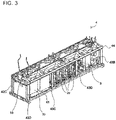
- Fig. 3 is a perspective view of a machine chamber 4 illustrating the chilling unit 100 according to Embodiment 1.
- Fig. 4 is a schematic diagram illustrating the placement of a first heat-source heat exchanger 1A in the chilling unit 100 according to Embodiment 1.
- Fig. 2 illustrates the chilling unit 100 as viewed in the direction of an arrow A in Fig. 1 .
- Fig. 3 illustrates the machine chamber 4 as viewed from where the opposite side of the chilling unit from that illustrated in Fig. 2 is disposed.
- Fig. 1 is a perspective view of a chilling unit 100 according to Embodiment 1.
- Fig. 2 is a side view of the chilling unit 100 according to Embodiment 1.
- Fig. 3 is a perspective view of a machine chamber 4 illustrating
- the chilling unit 100 receives a heat medium, such as water or antifreeze, from a use-side unit (not illustrated).
- the heat medium is cooled or heated in the chilling unit 100 and is then sent and supplied to the use-side unit.
- the circulation of the heat medium causes the use-side unit to be supplied with cooling energy or heating energy.
- the chilling unit 100 includes, in a casing 1, the first heat-source heat exchanger 1A, the second heat-source heat exchanger 1B, the third heat-source heat exchanger 1C, and the fourth heat-source heat exchanger 1D, which are included in a refrigeration cycle on a heat source side.
- the first heat-source heat exchanger 1A, the second heat-source heat exchanger 1B, the third heat-source heat exchanger 1C, and the fourth heat-source heat exchanger 1D may be referred to as a heat-source heat exchanger 2.
- the chilling unit 100 further includes a first fan 5A, a second fan 5B, a third fan 5C, and a fourth fan 5D.
- the first fan 5A, the second fan 5B, the third fan 5C, and the fourth fan 5D may be referred to as a fan 5.
- the chilling unit 100 has the machine chamber 4, which has a cuboid shape.
- a top frame 60 is disposed above the first heat-source heat exchanger 1A, the second heat-source heat exchanger 1B, the third heat-source heat exchanger 1C, and the fourth heat-source heat exchanger 1D.
- the top frame 60 has the first fan 5A, the second fan 5B, the third fan 5C, and the fourth fan 5D.
- Each of the first fan 5A, the second fan 5B, the third fan 5C, and the fourth fan 5D is covered with a fan guard (not illustrated).
- a dashed line represents a space occupied by the machine chamber 4.
- the machine chamber 4 has a support 41, four pillars, four intermediate columns, and an upper beam 44.
- the four pillars are a pillar 42A, a pillar 42B, a pillar 42C, and a pillar 42D.
- the four intermediate columns are an intermediate column 43A, an intermediate column 43B, an intermediate column 43C, and an intermediate column 43D.
- the support 41 is a rectangular flat part.
- the pillars 42A, 42B, 42C, and 42D are arranged at four corners of the support 41 and extend perpendicularly to the support 41.
- the intermediate columns 43A and 43B are spaced apart between the pillars 42A and 42C in a longitudinal direction of the support 41.
- the intermediate columns 43C and 43D are spaced apart between the pillars 42B and 42D in the longitudinal direction of the support 41.
- the intermediate columns 43A, 43B, 43C, and 43D extend perpendicularly to the support 41.
- the upper beam 44 is disposed on the pillars 42A, 42B, 42C, and 42D and the intermediate columns 43A, 43B, 43C, and 43D.
- the machine chamber 4 contains multiple element devices.
- the devices contained in the machine chamber 4 include a refrigerant-to-heat medium heat exchanger 3, a compressor 20 included in a refrigerant circuit 19, and a control unit 30.
- the pillars 42A, 42B, 42C, and 42D may be collectively referred to as pillars 42.
- the intermediate columns 43A, 43B, 43C, and 43D may be collectively referred to as intermediate columns 43.
- the first heat-source heat exchanger 1A and the second heat-source heat exchanger 1B facing each other in a lateral direction of the machine chamber 4 are inclined such that the distance between ends of the heat exchangers remote from the machine chamber 4 is larger than the distance between ends of the heat exchangers adjacent to the machine chamber 4.
- the first heat-source heat exchanger 1A and the second heat-source heat exchanger 1B are inclined to form a V-shape as viewed from the side of the chilling unit 100.
- the third heat-source heat exchanger 1C and the fourth heat-source heat exchanger 1D facing each other in the lateral direction of the machine chamber 4 are also similarly inclined to form a V-shape.
- the first heat-source heat exchanger 1A is inclined at an angle ⁇ of from 65 to 80 degrees.
- the second heat-source heat exchanger 1B, the third heat-source heat exchanger 1C, and the fourth heat-source heat exchanger 1D are inclined at the same angle as the angle ⁇ .
- the upper beam 44 of the machine chamber 4 has a base 10.
- the base 10 is supported by the pillars 42 and the intermediate columns 43.
- the base 10 has multiple rubber sheets.
- the first heat-source heat exchanger 1A, the second heat-source heat exchanger 1B, the third heat-source heat exchanger 1C, and the fourth heat-source heat exchanger 1D are arranged on the base 10, with the rubber sheets placed therebetween.
- the first heat-source heat exchanger 1A, the second heat-source heat exchanger 1B, the third heat-source heat exchanger 1C, and the fourth heat-source heat exchanger 1D are inclined in the above-described manner.
- a side panel 50 is disposed between the first heat-source heat exchanger 1A and the third heat-source heat exchanger 1C.
- a side panel 51 is disposed between the first heat-source heat exchanger 1A and the second heat-source heat exchanger 1B.
- a side panel (not illustrated) similar to the side panel 50 is disposed between the second heat-source heat exchanger 1B and the fourth heat-source heat exchanger 1D.
- a side panel (not illustrated) similar to the side panel 51 is disposed between the third heat-source heat exchanger 1C and the fourth heat-source heat exchanger 1D.
- the first heat-source heat exchanger 1A, the second heat-source heat exchanger 1B, the third heat-source heat exchanger 1C, and the fourth heat-source heat exchanger 1D are parallel-flow heat exchangers, and each include a pair of headers, multiple aluminum flat tubes, and multiple corrugated fins.
- the aluminum flat tubes are arranged between the pair of headers and are connected at opposite ends to the headers.
- the aluminum flat tubes are spaced apart parallel to each other between the pair of headers such that flat portions of the tubes face each other.
- the corrugated fins are arranged between the facing flat portions of the aluminum flat tubes.
- the first to fourth heat-source heat exchangers 1A to 1D are bent at an angle of 90 degrees such that, when viewed in a direction orthogonal to the aluminum flat tubes, a portion of each aluminum flat tube that is located at a slight distance from the middle thereof in a longitudinal direction thereof is bent.
- the first heat-source heat exchanger 1A, the second heat-source heat exchanger 1B, the third heat-source heat exchanger 1C, and the fourth heat-source heat exchanger 1D are L-shaped when viewed from where first ends of the headers are located.
- the first heat-source heat exchanger 1A faces the second heat-source heat exchanger 1B in the lateral direction of the machine chamber 4.
- the third heat-source heat exchanger 1C faces the fourth heat-source heat exchanger 1D in the lateral direction of the machine chamber 4.
- the first heat-source heat exchanger 1A and the third heat-source heat exchanger 1C are arranged side by side in the longitudinal direction of the machine chamber 4.
- the second heat-source heat exchanger 1B and the fourth heat-source heat exchanger 1D are arranged side by side in the longitudinal direction of the machine chamber 4.
- a short side portion 1AS of the first heat-source heat exchanger 1A faces a short side portion 1BS of the second heat-source heat exchanger 1B in the longitudinal direction of the machine chamber 4.
- a short side portion 1CS of the third heat-source heat exchanger 1C faces a short side portion 1DS of the fourth heat-source heat exchanger 1D in the longitudinal direction of the machine chamber 4.
- a long side portion 1AL of the first heat-source heat exchanger 1A and a long side portion 1CL of the third heat-source heat exchanger 1C are arranged side by side in the longitudinal direction of the machine chamber 4.
- a long side portion 1 BL of the second heat-source heat exchanger 1B and a long side portion 1DL of the fourth heat-source heat exchanger 1D are arranged side by side in the longitudinal direction of the machine chamber 4.
- the first heat-source heat exchanger 1A and the second heat-source heat exchanger 1B arranged in the above-described manner form a rectangle.
- An edge 1AE, along which the short side portion 1AS and the long side portion 1AL meet, of the first heat-source heat exchanger 1A is located at one corner of the rectangle.
- An edge 1BE, along which the short side portion 1BS and the long side portion 1BL meet, of the second heat-source heat exchanger 1B is located at one corner of the rectangle.
- the third heat-source heat exchanger 1C and the fourth heat-source heat exchanger 1D form a rectangle.
- An edge 1CE, along which the short side portion 1CS and the long side portion 1CL meet, of the third heat-source heat exchanger 1C is located at one corner of the rectangle.
- An edge 1DE, along which the short side portion 1DS and the long side portion 1DL meet, of the fourth heat-source heat exchanger 1D is located at one corner of the rectangle.
- the arrangement of the heat-source heat exchangers in Fig. 4 is merely an example.
- the heat-source heat exchangers may be arranged in a different manner.
- Fig. 5 is a circuit diagram illustrating the chilling unit 100 according to Embodiment 1.
- the chilling unit 100 includes the casing 1, the refrigerant circuit 19, an injection circuit 11, a heat medium circuit 15, and the control unit 30.
- the refrigerant circuit 19, the injection circuit 11, the heat medium circuit 15, and the control unit 30 are placed in the casing 1.
- the compressor 20, a flow switching device 21, the heat-source heat exchanger 2, a first expansion unit 22a, a second expansion unit 22b, the refrigerant-to-heat medium heat exchanger 3, and an accumulator 23 are connected by a refrigerant pipe 19a, thus forming the refrigerant circuit 19.
- the compressor 20 sucks low-temperature, low-pressure refrigerant, compresses the sucked refrigerant into high-temperature, high-pressure refrigerant, and discharges the refrigerant.
- the flow switching device 21 switches between refrigerant flow directions in the refrigerant circuit 19.
- the flow switching device 21 is, for example, a four-way valve.
- the flow switching device 21 is connected to the compressor 20, and switches the direction of flow of refrigerant through the refrigerant circuit 19 to that for a cooling operation or a heating operation.
- the heat-source heat exchanger 2 is an air heat exchanger that exchanges heat between refrigerant and, for example, outdoor air.
- the heat-source heat exchanger 2 operates as a condenser in the cooling operation and operates as an evaporator in the heating operation.
- the casing 1 contains the fan 5.
- the fan 5 is a device that sends the outdoor air to the heat-source heat exchanger 2.
- the first expansion unit 22a is a pressure reducing valve or expansion valve that reduces the pressure of refrigerant to expand the refrigerant.
- the first expansion unit 22a is, for example, an electronic expansion valve whose opening degree is adjustable.
- the second expansion unit 22b is a pressure reducing valve or expansion valve that reduces the pressure of refrigerant to expand the refrigerant.
- the second expansion unit 22b is, for example, an electronic expansion valve whose opening degree is adjustable.
- the refrigerant-to-heat medium heat exchanger 3 exchanges heat between the heat medium flowing through the heat medium circuit 15 and the refrigerant.
- the refrigerant-to-heat medium heat exchanger 3 operates as an evaporator in the cooling operation and operates as a condenser in the heating operation.
- the distance between the first expansion unit 22a and the second expansion unit 22b is 1 m or less.
- the compressor 20, the flow switching device 21, the heat-source heat exchanger 2, the first expansion unit 22a, the second expansion unit 22b, the refrigerant-to-heat medium heat exchanger 3, and the accumulator 23 are placed in the single casing 1. This placement allows a reduction in length of the refrigerant pipe 19a included in the refrigerant circuit 19. This also allows the distance between the first expansion unit 22a and the second expansion unit 22b to be 1 m or less.
- a portion between the first expansion unit 22a and the second expansion unit 22b is connected to the compressor 20 by an injection pipe 11a, thus forming the injection circuit 11.
- the injection circuit 11 includes an injection expansion unit 12, which reduces the pressure of refrigerant flowing through the injection pipe 11a to expand the refrigerant.
- the injection pipe 11a communicates with a suction chamber of the compressor 20.
- Embodiment 1 uses the suction chamber injection method, which allows for high volumetric efficiency and enables the first expansion unit 22a and the second expansion unit 22b to be located away from the compressor 20. This eliminates the need for a measure against stress.
- the refrigerant-to-heat medium heat exchanger 3 is connected to the use-side unit by a heat medium pipe 15a, thus forming the heat medium circuit 15.
- the control unit 30 is configured as dedicated hardware or a central processing unit (CPU) (also called a processing unit, an arithmetic unit, a microprocessor, a microcomputer, or a processor) that runs a program stored in a storage device.
- CPU central processing unit
- the control unit 30 corresponds to, for example, a single circuit, a composite circuit, an application specific integrated circuit (ASIC), a field-programmable gate array (FPGA), or a combination thereof.
- Functional parts that the control unit 30 implements may be implemented by individual hardware components or may be implemented by a single hardware component.
- control unit 30 In the case where the control unit 30 is a CPU, functions that the control unit 30 performs are implemented by software, firmware, or a combination of software and firmware.
- Software and firmware are described as programs and are stored in the storage device. The CPU reads the programs stored in the storage device and runs the programs, thus implementing the functions.
- a subset of the functions of the control unit 30 may be implemented by dedicated hardware, and another subset thereof may be implemented by software or firmware.
- the storage device may be configured as a hard disk or a volatile storage device capable of temporarily storing data, for example, a random access memory (RAM).
- RAM random access memory
- the storage device may be configured as a nonvolatile storage device capable of storing data for a long time, for example, a flash memory.
- Operation modes of the chilling unit 100 according to Embodiment 1 include a cooling operation mode and a heating operation mode.
- the control unit 30 fully opens the first expansion unit 22a to adjust the opening degree of the second expansion unit 22b.
- the heat-source heat exchanger 2 condenses and liquefies the refrigerant.
- the liquid refrigerant while being in a liquid state, flows out of the first expansion unit 22a, which is fully opened. Part of the liquid refrigerant flows through the injection pipe 11a and is then injected into the compressor 20.
- the refrigerant circuit 19 and the injection circuit 11 are placed in the casing 1. Such a configuration results in a small amount of refrigerant enclosed in the refrigerant circuit.
- the first expansion unit 22a does not need to turn the liquid refrigerant into two-phase gas-liquid refrigerant.
- the first expansion unit 22a can be fully opened.
- the degree of superheat of the refrigerant is controlled in the second expansion unit 22b.
- the control unit 30 fully opens the second expansion unit 22b to adjust the opening degree of the first expansion unit 22a.
- the refrigerant-to-heat medium heat exchanger 3 condenses and liquefies the refrigerant.
- the liquid refrigerant while being in the liquid state, flows out of the second expansion unit 22b, which is fully opened. Part of the liquid refrigerant flows through the injection pipe 11a and is then injected into the compressor 20.
- the chilling unit 100 the refrigerant circuit 19 and the injection circuit 11 are placed in the casing 1. This configuration results in a small amount of refrigerant enclosed in the refrigerant circuit. This eliminates the need for a further reduction in the amount of refrigerant enclosed.
- the second expansion unit 22b does not need to turn the liquid refrigerant into two-phase gas-liquid refrigerant.
- the second expansion unit 22b can be fully opened.
- the degree of superheat of the refrigerant is controlled in the first expansion unit 22a.
- Fig. 6 is a flowchart illustrating an operation of the control unit 30 in Embodiment 1. The operation of the control unit 30 will now be described with reference to the flowchart.
- the control unit 30 when the cooling operation is started (step ST1), the control unit 30 fully opens the first expansion unit 22a (step ST2). Then, the control unit 30 adjusts the opening degree of the second expansion unit 22b to adjust the temperature of the refrigerant (step ST3).
- the refrigerant sucked into the compressor 20 is compressed into high-temperature and high-pressure gas refrigerant by the compressor 20 and is then discharged therefrom.
- the high-temperature and high-pressure gas refrigerant discharged from the compressor 20 passes through the flow switching device 21 and enters the heat-source heat exchanger 2 operating as a condenser.
- the heat-source heat exchanger 2 the refrigerant exchanges heat with the outdoor air sent by the fan 5 and thus condenses into liquid.
- the condensed liquid refrigerant then enters the first expansion unit 22a fully opened and then flows out thereof while remaining unchanged.
- the liquid refrigerant is divided into two streams.
- One stream of the refrigerant enters the second expansion unit 22b.
- the refrigerant is expanded and reduced in pressure into low-temperature and low-pressure, two-phase gas-liquid refrigerant by the second expansion unit 22b.
- the two-phase gas-liquid refrigerant enters the refrigerant-to-heat medium heat exchanger 3 operating as an evaporator.
- the refrigerant-to-heat medium heat exchanger 3 the refrigerant exchanges heat with the heat medium flowing through the heat medium pipe 15a and thus evaporates into gas. At this time, the heat medium is cooled.
- the evaporated, low-temperature, low-pressure gas refrigerant passes through the flow switching device 21 and is then sucked into the compressor 20.
- Part of the liquid refrigerant leaving the first expansion unit 22a flows through the injection pipe 11a and is then expanded and reduced in pressure by the injection expansion unit 12.
- the refrigerant expanded and reduced in pressure is then sucked into the suction chamber of the compressor 20.
- Fig. 7 is a flowchart illustrating an operation of the control unit 30 in Embodiment 1. The operation of the control unit 30 will now be described with reference to the flowchart.
- the control unit 30 when the heating operation is started (step ST11), the control unit 30 fully opens the second expansion unit 22b (step ST12). Then, the control unit 30 adjusts the opening degree of the first expansion unit 22a to adjust the temperature of the refrigerant (step ST13).
- the refrigerant sucked into the compressor 20 is compressed into high-temperature and high-pressure gas refrigerant by the compressor 20 and is then discharged therefrom.
- the high-temperature, high-pressure gas refrigerant discharged from the compressor 20 passes through the flow switching device 21 and enters the refrigerant-to-heat medium heat exchanger 3 operating as a condenser.
- the refrigerant-to-heat medium heat exchanger 3 the refrigerant exchanges heat with the heat medium flowing through the heat medium pipe 15a and thus condenses into liquid. At this time, the heat medium is heated.
- the condensed liquid refrigerant then enters the second expansion unit 22b fully opened and then flows out thereof while remaining unchanged.
- the liquid refrigerant is divided into two streams.
- One stream of the refrigerant enters the first expansion unit 22a.
- the refrigerant is expanded and reduced in pressure into low-temperature, low-pressure and two-phase gas-liquid refrigerant by the first expansion unit 22a.
- the two-phase gas-liquid refrigerant enters the heat-source heat exchanger 2 operating as an evaporator.
- the heat-source heat exchanger 2 the refrigerant exchanges heat with the outdoor air sent by the fan 5 and thus evaporates into gas.
- the evaporated, low-temperature and low-pressure gas refrigerant passes through the flow switching device 21 and is then sucked into the compressor 20.
- Embodiment 1 the refrigerant circuit 19 and the injection circuit 11 are placed in the casing 1. This configuration results in a small amount of refrigerant enclosed in the refrigerant circuit 19. This eliminates the need for a further reduction in the amount of refrigerant enclosed. It is therefore unnecessary to liquefy the refrigerant to be injected into the compressor 20. Thus, the chilling unit 100 eliminates the need for a circuit to generate liquid refrigerant. As described above, in Embodiment 1, the first expansion unit 22a and the second expansion unit 22b, which are relatively inexpensive, may be placed instead of a circuit to generate liquid refrigerant, resulting in a reduction in cost.
- the distance between the first expansion unit 22a and the second expansion unit 22b is 1 m or less.
- the compressor 20, the flow switching device 21, the heat-source heat exchanger 2, the first expansion unit 22a, the second expansion unit 22b, the refrigerant-to-heat medium heat exchanger 3, and the accumulator 23 are placed in the single casing 1. This placement allows a reduction in length of the refrigerant pipe 19a included in the refrigerant circuit 19. This also allows the distance between the first expansion unit 22a and the second expansion unit 22b to be 1 m or less.
- the injection pipe 11a communicates with the suction chamber of the compressor 20.
- an increase in volume depends on the distance between the compressor 20 and an expansion unit, leading to lower volumetric efficiency. It is therefore necessary to dispose the expansion unit in the vicinity of the compressor 20. In this case, stress from the compressor 20 may affect the expansion unit.
- Embodiment 1 uses the suction chamber injection method, which allows for high volumetric efficiency and enables the first expansion unit 22a and the second expansion unit 22b to be located away from the compressor 20. This eliminates the need for a measure against stress.
- Embodiment 1 uses the suction chamber injection method, which can inhibit an excessive increase in discharge temperature of the refrigerant without any dilution of oil.
- the heat-source heat exchanger 2 condenses and liquefies the refrigerant.
- the liquid refrigerant while being in the liquid state, flows out of the first expansion unit 22a, which is fully opened. Part of the liquid refrigerant flows through the injection pipe 11a and is then injected into the compressor 20.
- the refrigerant circuit 19 and the injection circuit 11 are placed in the casing 1. This configuration results in a small amount of refrigerant enclosed in the refrigerant circuit. This eliminates the need for a further reduction in the amount of refrigerant enclosed. Therefore, the first expansion unit 22a does not need to turn the liquid refrigerant into two-phase gas-liquid refrigerant. Thus, the first expansion unit 22a can be fully opened.
- the refrigerant-to-heat medium heat exchanger 3 condenses and liquefies the refrigerant.
- the liquid refrigerant while being in the liquid state, flows out of the second expansion unit 22b, which is fully opened. Part of the liquid refrigerant flows through the injection pipe 11a and is then injected into the compressor 20.
- the chilling unit 100 the refrigerant circuit 19 and the injection circuit 11 are placed in the casing 1. This configuration results in a small amount of refrigerant enclosed in the refrigerant circuit. This eliminates the need for a further reduction in the amount of refrigerant enclosed. Therefore, the first expansion unit 22a does not need to turn the liquid refrigerant into two-phase gas-liquid refrigerant. Thus, the first expansion unit 22a can be fully opened.
- 1 casing, 1A: first heat-source heat exchanger, 1AE: edge, 1AL: long side portion, 1AS: short side portion, 1B: second heat-source heat exchanger, 1BE: edge, 1BL: long side portion, 1BS: short side portion, 1C: third heat-source heat exchanger, 1CE: edge, 1CL: long side portion, 1CS: short side portion, 1D: fourth heat-source heat exchanger, 1DE: edge, 1DL: long side portion, 1DS: short side portion, 2: heat-source heat exchanger, 3: refrigerant-to-heat medium heat exchanger, 4: machine chamber, 5: fan, 5A: first fan, 5B: second fan, 5C: third fan, 5D: fourth fan, 10: base, 11: injection circuit, 11 a: injection pipe, 12: injection expansion unit, 15: heat medium circuit, 15a: heat medium pipe, 19: refrigerant circuit, 19a: refrigerant pipe, 20: compressor, 21: flow switching device, 22a: first expansion unit, 22b:
Landscapes
- Engineering & Computer Science (AREA)
- Physics & Mathematics (AREA)
- Mechanical Engineering (AREA)
- Thermal Sciences (AREA)
- General Engineering & Computer Science (AREA)
- Other Air-Conditioning Systems (AREA)
Abstract
Description
- The present disclosure relates to a chilling unit including an injection circuit through which liquid refrigerant is injected into a compressor.
- A known chilling unit includes an injection circuit through which liquid refrigerant is injected into a compressor.
Patent Literature 1 discloses an air-conditioning apparatus in which refrigerant liquefied in a refrigerant heat exchanger disposed between a heat-source-side expansion device and a load-side expansion device is injected into a compressor.Patent Literature 1 states that two-phase gas-liquid refrigerant reduced in pressure to an intermediate pressure by the heat-source-side expansion device or the load-side expansion device is liquefied in the refrigerant heat exchanger and is then injected into the compressor. As described inPatent Literature 1, the heat-source-side expansion device is disposed in a heat-source-side unit, and the load-side expansion device is disposed in a load-side unit. Such a configuration generally results in a large amount of refrigerant enclosed in an air-conditioning apparatus. InPatent Literature 1, the heat-source-side expansion device or the load-side expansion device reduces the pressure of the refrigerant to the intermediate pressure to provide two-phase gas-liquid refrigerant, thus achieving a reduction in the amount of refrigerant enclosed. - Patent Literature 1:
Japanese Unexamined Patent Application Publication No. 2008-138921 - As described above, in the air-conditioning apparatus disclosed in
Patent Literature 1, the pressure of the refrigerant is reduced to the intermediate pressure by the heat-source-side expansion device or the load-side expansion device. Therefore, an additional circuit with, for example, the refrigerant heat exchanger, is needed to inject liquid refrigerant into the compressor. - To solve the above issue, the present disclosure has been made aiming at providing a chilling unit that eliminates the need for a circuit to generate liquid refrigerant that is to be injected.
- A chilling unit according to an embodiment of the present disclosure includes a casing, a refrigerant circuit in which a compressor, a heat-source heat exchanger, a first expansion unit, a second expansion unit, and a refrigerant-to-heat medium heat exchanger are connected by a refrigerant pipe and through which refrigerant flows, the refrigerant circuit being placed in the casing, and an injection circuit in which a portion between the first expansion unit and the second expansion unit is connected to the compressor by an injection pipe, the injection circuit being placed in the casing. Advantageous Effects of Invention
- According to the embodiment of the present disclosure, the refrigerant circuit and the injection circuit are placed in the casing. Such a configuration results in a small amount of refrigerant enclosed in the refrigerant circuit. This eliminates the need for a further reduction in the amount of refrigerant enclosed. It is therefore unnecessary to liquefy refrigerant that is to be injected into the compressor. Thus, the chilling unit eliminates the need for a circuit to generate liquid refrigerant.
-
- [
Fig. 1] Fig. 1 is a perspective view of a chilling unit according toEmbodiment 1. - [
Fig. 2] Fig. 2 is a side view of the chilling unit according to Embodiment 1. - [
Fig. 3] Fig. 3 is a perspective view of a machine chamber illustrating the chilling unit according toEmbodiment 1. - [
Fig. 4] Fig. 4 is a schematic diagram illustrating the placement of a first heat-source heat exchanger in the chilling unit according toEmbodiment 1. - [
Fig. 5] Fig. 5 is a circuit diagram illustrating the chilling unit according toEmbodiment 1. - [
Fig. 6] Fig. 6 is a flowchart illustrating an operation of a control unit inEmbodiment 1. - [
Fig. 7] Fig. 7 is a flowchart illustrating an operation of the control unit inEmbodiment 1. - Embodiments of a chilling unit according to the present disclosure will be described below with reference to the drawings. Note that the following embodiments should not be construed as limiting the present disclosure. Furthermore, note that the relationship between the sizes of components in the following figures including
Fig. 1 may differ from that between the actual sizes of the components. For the sake of easy understanding, terms representing directions will be used as appropriate. These terms are used herein only for the purpose of convenience of description, and should not be construed as limiting the present disclosure. Examples of the terms representing the directions include "upper", "lower", "right", "left", "front", and "rear". -
Fig. 1 is a perspective view of achilling unit 100 according toEmbodiment 1.Fig. 2 is a side view of thechilling unit 100 according toEmbodiment 1.Fig. 3 is a perspective view of amachine chamber 4 illustrating thechilling unit 100 according toEmbodiment 1.Fig. 4 is a schematic diagram illustrating the placement of a first heat-source heat exchanger 1A in thechilling unit 100 according toEmbodiment 1.Fig. 2 illustrates thechilling unit 100 as viewed in the direction of an arrow A inFig. 1 .Fig. 3 illustrates themachine chamber 4 as viewed from where the opposite side of the chilling unit from that illustrated inFig. 2 is disposed.Fig. 4 illustrates the first heat-source heat exchanger 1A, a second heat-source heat exchanger 1B, a third heat-source heat exchanger 1C, and a fourth heat-source heat exchanger 1D as viewed from above thechilling unit 100. Thechilling unit 100 according toEmbodiment 1 receives a heat medium, such as water or antifreeze, from a use-side unit (not illustrated). The heat medium is cooled or heated in thechilling unit 100 and is then sent and supplied to the use-side unit. The circulation of the heat medium causes the use-side unit to be supplied with cooling energy or heating energy. - As illustrated in
Figs. 1 to 4 , thechilling unit 100 includes, in acasing 1, the first heat-source heat exchanger 1A, the second heat-source heat exchanger 1B, the third heat-source heat exchanger 1C, and the fourth heat-source heat exchanger 1D, which are included in a refrigeration cycle on a heat source side. The first heat-source heat exchanger 1A, the second heat-source heat exchanger 1B, the third heat-source heat exchanger 1C, and the fourth heat-source heat exchanger 1D may be referred to as a heat-source heat exchanger 2. Thechilling unit 100 further includes afirst fan 5A, asecond fan 5B, athird fan 5C, and afourth fan 5D. Thefirst fan 5A, thesecond fan 5B, thethird fan 5C, and thefourth fan 5D may be referred to as afan 5. Thechilling unit 100 has themachine chamber 4, which has a cuboid shape. - A
top frame 60 is disposed above the first heat-source heat exchanger 1A, the second heat-source heat exchanger 1B, the third heat-source heat exchanger 1C, and the fourth heat-source heat exchanger 1D. Thetop frame 60 has thefirst fan 5A, thesecond fan 5B, thethird fan 5C, and thefourth fan 5D. Each of thefirst fan 5A, thesecond fan 5B, thethird fan 5C, and thefourth fan 5D is covered with a fan guard (not illustrated). - In
Fig. 1 , a dashed line represents a space occupied by themachine chamber 4. Themachine chamber 4 has asupport 41, four pillars, four intermediate columns, and anupper beam 44. The four pillars are apillar 42A, apillar 42B, apillar 42C, and apillar 42D. The four intermediate columns are anintermediate column 43A, anintermediate column 43B, anintermediate column 43C, and anintermediate column 43D. Thesupport 41 is a rectangular flat part. Thepillars support 41 and extend perpendicularly to thesupport 41. Theintermediate columns pillars support 41. - The
intermediate columns pillars support 41. Theintermediate columns support 41. Theupper beam 44 is disposed on thepillars intermediate columns machine chamber 4 contains multiple element devices. The devices contained in themachine chamber 4 include a refrigerant-to-heatmedium heat exchanger 3, acompressor 20 included in arefrigerant circuit 19, and acontrol unit 30. Thepillars intermediate columns - Furthermore, as illustrated in
Fig. 2 , the first heat-source heat exchanger 1A and the second heat-source heat exchanger 1B facing each other in a lateral direction of themachine chamber 4 are inclined such that the distance between ends of the heat exchangers remote from themachine chamber 4 is larger than the distance between ends of the heat exchangers adjacent to themachine chamber 4. In other words, the first heat-source heat exchanger 1A and the second heat-source heat exchanger 1B are inclined to form a V-shape as viewed from the side of thechilling unit 100. The third heat-source heat exchanger 1C and the fourth heat-source heat exchanger 1D facing each other in the lateral direction of themachine chamber 4 are also similarly inclined to form a V-shape. InEmbodiment 1, the first heat-source heat exchanger 1A is inclined at an angle α of from 65 to 80 degrees. The second heat-source heat exchanger 1B, the third heat-source heat exchanger 1C, and the fourth heat-source heat exchanger 1D are inclined at the same angle as the angle α. - As illustrated in
Fig. 3 , theupper beam 44 of themachine chamber 4 has abase 10. Thebase 10 is supported by the pillars 42 and the intermediate columns 43. Thebase 10 has multiple rubber sheets. The first heat-source heat exchanger 1A, the second heat-source heat exchanger 1B, the third heat-source heat exchanger 1C, and the fourth heat-source heat exchanger 1D are arranged on thebase 10, with the rubber sheets placed therebetween. The first heat-source heat exchanger 1A, the second heat-source heat exchanger 1B, the third heat-source heat exchanger 1C, and the fourth heat-source heat exchanger 1D are inclined in the above-described manner. Aside panel 50 is disposed between the first heat-source heat exchanger 1A and the third heat-source heat exchanger 1C. Aside panel 51 is disposed between the first heat-source heat exchanger 1A and the second heat-source heat exchanger 1B. In addition, a side panel (not illustrated) similar to theside panel 50 is disposed between the second heat-source heat exchanger 1B and the fourth heat-source heat exchanger 1D. Additionally, a side panel (not illustrated) similar to theside panel 51 is disposed between the third heat-source heat exchanger 1C and the fourth heat-source heat exchanger 1D. - The first heat-
source heat exchanger 1A, the second heat-source heat exchanger 1B, the third heat-source heat exchanger 1C, and the fourth heat-source heat exchanger 1D are parallel-flow heat exchangers, and each include a pair of headers, multiple aluminum flat tubes, and multiple corrugated fins. The aluminum flat tubes are arranged between the pair of headers and are connected at opposite ends to the headers. The aluminum flat tubes are spaced apart parallel to each other between the pair of headers such that flat portions of the tubes face each other. The corrugated fins are arranged between the facing flat portions of the aluminum flat tubes. - As illustrated in
Fig. 4 , the first to fourth heat-source heat exchangers 1A to 1D are bent at an angle of 90 degrees such that, when viewed in a direction orthogonal to the aluminum flat tubes, a portion of each aluminum flat tube that is located at a slight distance from the middle thereof in a longitudinal direction thereof is bent. In other words, the first heat-source heat exchanger 1A, the second heat-source heat exchanger 1B, the third heat-source heat exchanger 1C, and the fourth heat-source heat exchanger 1D are L-shaped when viewed from where first ends of the headers are located. The first heat-source heat exchanger 1A faces the second heat-source heat exchanger 1B in the lateral direction of themachine chamber 4. The third heat-source heat exchanger 1C faces the fourth heat-source heat exchanger 1D in the lateral direction of themachine chamber 4. The first heat-source heat exchanger 1A and the third heat-source heat exchanger 1C are arranged side by side in the longitudinal direction of themachine chamber 4. The second heat-source heat exchanger 1B and the fourth heat-source heat exchanger 1D are arranged side by side in the longitudinal direction of themachine chamber 4. - Furthermore, a short side portion 1AS of the first heat-
source heat exchanger 1A faces a short side portion 1BS of the second heat-source heat exchanger 1B in the longitudinal direction of themachine chamber 4. A short side portion 1CS of the third heat-source heat exchanger 1C faces a short side portion 1DS of the fourth heat-source heat exchanger 1D in the longitudinal direction of themachine chamber 4. In addition, a long side portion 1AL of the first heat-source heat exchanger 1A and a long side portion 1CL of the third heat-source heat exchanger 1C are arranged side by side in the longitudinal direction of themachine chamber 4. Along side portion 1 BL of the second heat-source heat exchanger 1B and a long side portion 1DL of the fourth heat-source heat exchanger 1D are arranged side by side in the longitudinal direction of themachine chamber 4. The first heat-source heat exchanger 1A and the second heat-source heat exchanger 1B arranged in the above-described manner form a rectangle. An edge 1AE, along which the short side portion 1AS and the long side portion 1AL meet, of the first heat-source heat exchanger 1A is located at one corner of the rectangle. An edge 1BE, along which the short side portion 1BS and the long side portion 1BL meet, of the second heat-source heat exchanger 1B is located at one corner of the rectangle. Furthermore, the third heat-source heat exchanger 1C and the fourth heat-source heat exchanger 1D form a rectangle. An edge 1CE, along which the short side portion 1CS and the long side portion 1CL meet, of the third heat-source heat exchanger 1C is located at one corner of the rectangle. An edge 1DE, along which the short side portion 1DS and the long side portion 1DL meet, of the fourth heat-source heat exchanger 1D is located at one corner of the rectangle. The arrangement of the heat-source heat exchangers inFig. 4 is merely an example. The heat-source heat exchangers may be arranged in a different manner. - In the
chilling unit 100 according toEmbodiment 1, incoming airflows in a direction orthogonal to long sides of the aluminum flat tubes of the first heat-source heat exchanger 1A, the second heat-source heat exchanger 1B, the third heat-source heat exchanger 1C, and the fourth heat-source heat exchanger 1D. Therefore, the incoming air is guided to spaces between the facing flat portions of the aluminum flat tubes, and flows in a direction along the width of the aluminum flat tubes, or orthogonally to the longitudinal direction of the aluminum flat tubes. -
Fig. 5 is a circuit diagram illustrating thechilling unit 100 according toEmbodiment 1. As illustrated inFig. 5 , thechilling unit 100 includes thecasing 1, therefrigerant circuit 19, aninjection circuit 11, aheat medium circuit 15, and thecontrol unit 30. Therefrigerant circuit 19, theinjection circuit 11, theheat medium circuit 15, and thecontrol unit 30 are placed in thecasing 1. - The
compressor 20, aflow switching device 21, the heat-source heat exchanger 2, afirst expansion unit 22a, asecond expansion unit 22b, the refrigerant-to-heatmedium heat exchanger 3, and anaccumulator 23 are connected by arefrigerant pipe 19a, thus forming therefrigerant circuit 19. Thecompressor 20 sucks low-temperature, low-pressure refrigerant, compresses the sucked refrigerant into high-temperature, high-pressure refrigerant, and discharges the refrigerant. Theflow switching device 21 switches between refrigerant flow directions in therefrigerant circuit 19. Theflow switching device 21 is, for example, a four-way valve. Theflow switching device 21 is connected to thecompressor 20, and switches the direction of flow of refrigerant through therefrigerant circuit 19 to that for a cooling operation or a heating operation. The heat-source heat exchanger 2 is an air heat exchanger that exchanges heat between refrigerant and, for example, outdoor air. The heat-source heat exchanger 2 operates as a condenser in the cooling operation and operates as an evaporator in the heating operation. Thecasing 1 contains thefan 5. Thefan 5 is a device that sends the outdoor air to the heat-source heat exchanger 2. - The
first expansion unit 22a is a pressure reducing valve or expansion valve that reduces the pressure of refrigerant to expand the refrigerant. Thefirst expansion unit 22a is, for example, an electronic expansion valve whose opening degree is adjustable. Thesecond expansion unit 22b is a pressure reducing valve or expansion valve that reduces the pressure of refrigerant to expand the refrigerant. Thesecond expansion unit 22b is, for example, an electronic expansion valve whose opening degree is adjustable. The refrigerant-to-heatmedium heat exchanger 3 exchanges heat between the heat medium flowing through theheat medium circuit 15 and the refrigerant. The refrigerant-to-heatmedium heat exchanger 3 operates as an evaporator in the cooling operation and operates as a condenser in the heating operation. - The distance between the
first expansion unit 22a and thesecond expansion unit 22b is 1 m or less. In thechilling unit 100, thecompressor 20, theflow switching device 21, the heat-source heat exchanger 2, thefirst expansion unit 22a, thesecond expansion unit 22b, the refrigerant-to-heatmedium heat exchanger 3, and theaccumulator 23 are placed in thesingle casing 1. This placement allows a reduction in length of therefrigerant pipe 19a included in therefrigerant circuit 19. This also allows the distance between thefirst expansion unit 22a and thesecond expansion unit 22b to be 1 m or less. Theaccumulator 23, which is disposed on a suction side of thecompressor 20, stores liquid refrigerant of the refrigerant to be sucked into thecompressor 20 so that gas refrigerant alone enters thecompressor 20. - A portion between the
first expansion unit 22a and thesecond expansion unit 22b is connected to thecompressor 20 by aninjection pipe 11a, thus forming theinjection circuit 11. Theinjection circuit 11 includes aninjection expansion unit 12, which reduces the pressure of refrigerant flowing through theinjection pipe 11a to expand the refrigerant. In theinjection circuit 11 inEmbodiment 1, which uses a suction chamber injection method, theinjection pipe 11a communicates with a suction chamber of thecompressor 20. - For an intermediate injection method in which intermediate-pressure and low-quality refrigerant is injected into the
compressor 20 during compression, an increase in volume depends on the distance between thecompressor 20 and an expansion unit, leading to lower volumetric efficiency. It is therefore necessary to dispose the expansion unit in the vicinity of thecompressor 20. In this case, stress from thecompressor 20 may affect the expansion unit. In contrast,Embodiment 1 uses the suction chamber injection method, which allows for high volumetric efficiency and enables thefirst expansion unit 22a and thesecond expansion unit 22b to be located away from thecompressor 20. This eliminates the need for a measure against stress. - The refrigerant-to-heat
medium heat exchanger 3 is connected to the use-side unit by aheat medium pipe 15a, thus forming theheat medium circuit 15. - The
control unit 30 is configured as dedicated hardware or a central processing unit (CPU) (also called a processing unit, an arithmetic unit, a microprocessor, a microcomputer, or a processor) that runs a program stored in a storage device. In the case where thecontrol unit 30 is dedicated hardware, thecontrol unit 30 corresponds to, for example, a single circuit, a composite circuit, an application specific integrated circuit (ASIC), a field-programmable gate array (FPGA), or a combination thereof. Functional parts that thecontrol unit 30 implements may be implemented by individual hardware components or may be implemented by a single hardware component. - In the case where the
control unit 30 is a CPU, functions that thecontrol unit 30 performs are implemented by software, firmware, or a combination of software and firmware. Software and firmware are described as programs and are stored in the storage device. The CPU reads the programs stored in the storage device and runs the programs, thus implementing the functions. A subset of the functions of thecontrol unit 30 may be implemented by dedicated hardware, and another subset thereof may be implemented by software or firmware. The storage device may be configured as a hard disk or a volatile storage device capable of temporarily storing data, for example, a random access memory (RAM). The storage device may be configured as a nonvolatile storage device capable of storing data for a long time, for example, a flash memory. - Operation modes of the
chilling unit 100 according toEmbodiment 1 include a cooling operation mode and a heating operation mode. In the cooling operation, thecontrol unit 30 fully opens thefirst expansion unit 22a to adjust the opening degree of thesecond expansion unit 22b. In the cooling operation, the heat-source heat exchanger 2 condenses and liquefies the refrigerant. The liquid refrigerant, while being in a liquid state, flows out of thefirst expansion unit 22a, which is fully opened. Part of the liquid refrigerant flows through theinjection pipe 11a and is then injected into thecompressor 20. In thechilling unit 100, therefrigerant circuit 19 and theinjection circuit 11 are placed in thecasing 1. Such a configuration results in a small amount of refrigerant enclosed in the refrigerant circuit. This eliminates the need for a further reduction in the amount of refrigerant enclosed. Therefore, thefirst expansion unit 22a does not need to turn the liquid refrigerant into two-phase gas-liquid refrigerant. Thus, thefirst expansion unit 22a can be fully opened. For the other part of the liquid refrigerant, or the refrigerant other than the refrigerant flowing through theinjection pipe 11a, the degree of superheat of the refrigerant is controlled in thesecond expansion unit 22b. - Furthermore, in the heating operation, the
control unit 30 fully opens thesecond expansion unit 22b to adjust the opening degree of thefirst expansion unit 22a. In the heating operation, the refrigerant-to-heatmedium heat exchanger 3 condenses and liquefies the refrigerant. The liquid refrigerant, while being in the liquid state, flows out of thesecond expansion unit 22b, which is fully opened. Part of the liquid refrigerant flows through theinjection pipe 11a and is then injected into thecompressor 20. In thechilling unit 100, therefrigerant circuit 19 and theinjection circuit 11 are placed in thecasing 1. This configuration results in a small amount of refrigerant enclosed in the refrigerant circuit. This eliminates the need for a further reduction in the amount of refrigerant enclosed. Therefore, thesecond expansion unit 22b does not need to turn the liquid refrigerant into two-phase gas-liquid refrigerant. Thus, thesecond expansion unit 22b can be fully opened. For the other part of the liquid refrigerant, or the refrigerant other than the refrigerant flowing through theinjection pipe 11a, the degree of superheat of the refrigerant is controlled in thefirst expansion unit 22a. -
Fig. 6 is a flowchart illustrating an operation of thecontrol unit 30 inEmbodiment 1. The operation of thecontrol unit 30 will now be described with reference to the flowchart. As illustrated inFig. 6 , when the cooling operation is started (step ST1), thecontrol unit 30 fully opens thefirst expansion unit 22a (step ST2). Then, thecontrol unit 30 adjusts the opening degree of thesecond expansion unit 22b to adjust the temperature of the refrigerant (step ST3). - The flow of the refrigerant in the cooling operation will now be described. In the cooling operation, the refrigerant sucked into the
compressor 20 is compressed into high-temperature and high-pressure gas refrigerant by thecompressor 20 and is then discharged therefrom. The high-temperature and high-pressure gas refrigerant discharged from thecompressor 20 passes through theflow switching device 21 and enters the heat-source heat exchanger 2 operating as a condenser. In the heat-source heat exchanger 2, the refrigerant exchanges heat with the outdoor air sent by thefan 5 and thus condenses into liquid. The condensed liquid refrigerant then enters thefirst expansion unit 22a fully opened and then flows out thereof while remaining unchanged. The liquid refrigerant is divided into two streams. One stream of the refrigerant enters thesecond expansion unit 22b. The refrigerant is expanded and reduced in pressure into low-temperature and low-pressure, two-phase gas-liquid refrigerant by thesecond expansion unit 22b. Then, the two-phase gas-liquid refrigerant enters the refrigerant-to-heatmedium heat exchanger 3 operating as an evaporator. In the refrigerant-to-heatmedium heat exchanger 3, the refrigerant exchanges heat with the heat medium flowing through theheat medium pipe 15a and thus evaporates into gas. At this time, the heat medium is cooled. The evaporated, low-temperature, low-pressure gas refrigerant passes through theflow switching device 21 and is then sucked into thecompressor 20. - Part of the liquid refrigerant leaving the
first expansion unit 22a flows through theinjection pipe 11a and is then expanded and reduced in pressure by theinjection expansion unit 12. The refrigerant expanded and reduced in pressure is then sucked into the suction chamber of thecompressor 20. -
Fig. 7 is a flowchart illustrating an operation of thecontrol unit 30 inEmbodiment 1. The operation of thecontrol unit 30 will now be described with reference to the flowchart. As illustrated inFig. 7 , when the heating operation is started (step ST11), thecontrol unit 30 fully opens thesecond expansion unit 22b (step ST12). Then, thecontrol unit 30 adjusts the opening degree of thefirst expansion unit 22a to adjust the temperature of the refrigerant (step ST13). - The flow of the refrigerant in the heating operation will now be described. In the heating operation, the refrigerant sucked into the
compressor 20 is compressed into high-temperature and high-pressure gas refrigerant by thecompressor 20 and is then discharged therefrom. The high-temperature, high-pressure gas refrigerant discharged from thecompressor 20 passes through theflow switching device 21 and enters the refrigerant-to-heatmedium heat exchanger 3 operating as a condenser. In the refrigerant-to-heatmedium heat exchanger 3, the refrigerant exchanges heat with the heat medium flowing through theheat medium pipe 15a and thus condenses into liquid. At this time, the heat medium is heated. The condensed liquid refrigerant then enters thesecond expansion unit 22b fully opened and then flows out thereof while remaining unchanged. The liquid refrigerant is divided into two streams. One stream of the refrigerant enters thefirst expansion unit 22a. The refrigerant is expanded and reduced in pressure into low-temperature, low-pressure and two-phase gas-liquid refrigerant by thefirst expansion unit 22a. Then, the two-phase gas-liquid refrigerant enters the heat-source heat exchanger 2 operating as an evaporator. In the heat-source heat exchanger 2, the refrigerant exchanges heat with the outdoor air sent by thefan 5 and thus evaporates into gas. The evaporated, low-temperature and low-pressure gas refrigerant passes through theflow switching device 21 and is then sucked into thecompressor 20. - Part of the liquid refrigerant leaving the
second expansion unit 22b flows through theinjection pipe 11a and is then expanded and reduced in pressure by theinjection expansion unit 12. The refrigerant expanded and reduced in pressure is then sucked into the suction chamber of thecompressor 20. - In
Embodiment 1, therefrigerant circuit 19 and theinjection circuit 11 are placed in thecasing 1. This configuration results in a small amount of refrigerant enclosed in therefrigerant circuit 19. This eliminates the need for a further reduction in the amount of refrigerant enclosed. It is therefore unnecessary to liquefy the refrigerant to be injected into thecompressor 20. Thus, thechilling unit 100 eliminates the need for a circuit to generate liquid refrigerant. As described above, inEmbodiment 1, thefirst expansion unit 22a and thesecond expansion unit 22b, which are relatively inexpensive, may be placed instead of a circuit to generate liquid refrigerant, resulting in a reduction in cost. - The distance between the
first expansion unit 22a and thesecond expansion unit 22b is 1 m or less. In thechilling unit 100, thecompressor 20, theflow switching device 21, the heat-source heat exchanger 2, thefirst expansion unit 22a, thesecond expansion unit 22b, the refrigerant-to-heatmedium heat exchanger 3, and theaccumulator 23 are placed in thesingle casing 1. This placement allows a reduction in length of therefrigerant pipe 19a included in therefrigerant circuit 19. This also allows the distance between thefirst expansion unit 22a and thesecond expansion unit 22b to be 1 m or less. - The
injection pipe 11a communicates with the suction chamber of thecompressor 20. For the intermediate injection method in which intermediate-pressure and low-quality refrigerant is injected into thecompressor 20 during compression, an increase in volume depends on the distance between thecompressor 20 and an expansion unit, leading to lower volumetric efficiency. It is therefore necessary to dispose the expansion unit in the vicinity of thecompressor 20. In this case, stress from thecompressor 20 may affect the expansion unit. In contrast,Embodiment 1 uses the suction chamber injection method, which allows for high volumetric efficiency and enables thefirst expansion unit 22a and thesecond expansion unit 22b to be located away from thecompressor 20. This eliminates the need for a measure against stress. For a suction pipe injection method, in which liquid refrigerant flows into a suction pipe disposed on the suction side of thecompressor 20, oil may be diluted. In contrast,Embodiment 1 uses the suction chamber injection method, which can inhibit an excessive increase in discharge temperature of the refrigerant without any dilution of oil. - In the cooling operation, the heat-
source heat exchanger 2 condenses and liquefies the refrigerant. The liquid refrigerant, while being in the liquid state, flows out of thefirst expansion unit 22a, which is fully opened. Part of the liquid refrigerant flows through theinjection pipe 11a and is then injected into thecompressor 20. In thechilling unit 100, therefrigerant circuit 19 and theinjection circuit 11 are placed in thecasing 1. This configuration results in a small amount of refrigerant enclosed in the refrigerant circuit. This eliminates the need for a further reduction in the amount of refrigerant enclosed. Therefore, thefirst expansion unit 22a does not need to turn the liquid refrigerant into two-phase gas-liquid refrigerant. Thus, thefirst expansion unit 22a can be fully opened. - In the heating operation, the refrigerant-to-heat
medium heat exchanger 3 condenses and liquefies the refrigerant. The liquid refrigerant, while being in the liquid state, flows out of thesecond expansion unit 22b, which is fully opened. Part of the liquid refrigerant flows through theinjection pipe 11a and is then injected into thecompressor 20. In thechilling unit 100, therefrigerant circuit 19 and theinjection circuit 11 are placed in thecasing 1. This configuration results in a small amount of refrigerant enclosed in the refrigerant circuit. This eliminates the need for a further reduction in the amount of refrigerant enclosed. Therefore, thefirst expansion unit 22a does not need to turn the liquid refrigerant into two-phase gas-liquid refrigerant. Thus, thefirst expansion unit 22a can be fully opened. - 1: casing, 1A: first heat-source heat exchanger, 1AE: edge, 1AL: long side portion, 1AS: short side portion, 1B: second heat-source heat exchanger, 1BE: edge, 1BL: long side portion, 1BS: short side portion, 1C: third heat-source heat exchanger, 1CE: edge, 1CL: long side portion, 1CS: short side portion, 1D: fourth heat-source heat exchanger, 1DE: edge, 1DL: long side portion, 1DS: short side portion, 2: heat-source heat exchanger, 3: refrigerant-to-heat medium heat exchanger, 4: machine chamber, 5: fan, 5A: first fan, 5B: second fan, 5C: third fan, 5D: fourth fan, 10: base, 11: injection circuit, 11 a: injection pipe, 12: injection expansion unit, 15: heat medium circuit, 15a: heat medium pipe, 19: refrigerant circuit, 19a: refrigerant pipe, 20: compressor, 21: flow switching device, 22a: first expansion unit, 22b: second expansion unit, 23: accumulator, 30: control unit, 41: support, 42: pillars, 42A: pillar, 42B: pillar, 42C: pillar, 42D: pillar, 43: intermediate columns, 43A: intermediate column, 43B: intermediate column, 43C: intermediate column, 43D: intermediate column, 44: upper beam, 50: side panel, 51: side panel, 60: top frame, 100: chilling unit
Claims (5)
- A chilling unit comprising:
a casing:a refrigerant circuit in which a compressor, a heat-source heat exchanger, a first expansion unit, a second expansion unit, and a refrigerant-to-heat medium heat exchanger are connected by a refrigerant pipe and through which refrigerant flows, the refrigerant circuit being placed in the casing; andan injection circuit in which a portion between the first expansion unit and the second expansion unit is connected to the compressor by an injection pipe, the injection circuit being placed in the casing. - The chilling unit of claim 1, wherein a distance between the first expansion unit and the second expansion unit is 1 m or less.
- The chilling unit of claim 1 or 2, wherein the injection pipe communicates with a suction chamber of the compressor.
- The chilling unit of any one of claims 1 to 3, further comprising:
a control unit configured to fully open the first expansion unit to adjust an opening degree of the second expansion unit. - The chilling unit of any one of claims 1 to 3, further comprising:
a control unit configured to fully open the second expansion unit to adjust an opening degree of the first expansion unit.
Applications Claiming Priority (1)
| Application Number | Priority Date | Filing Date | Title |
|---|---|---|---|
| PCT/JP2019/031085 WO2021024408A1 (en) | 2019-08-07 | 2019-08-07 | Chilling unit |
Publications (2)
| Publication Number | Publication Date |
|---|---|
| EP4012289A1 true EP4012289A1 (en) | 2022-06-15 |
| EP4012289A4 EP4012289A4 (en) | 2022-09-28 |
Family
ID=74503984
Family Applications (1)
| Application Number | Title | Priority Date | Filing Date |
|---|---|---|---|
| EP19940323.9A Pending EP4012289A4 (en) | 2019-08-07 | 2019-08-07 | COOLING UNIT |
Country Status (4)
| Country | Link |
|---|---|
| US (1) | US12038210B2 (en) |
| EP (1) | EP4012289A4 (en) |
| JP (1) | JPWO2021024408A1 (en) |
| WO (1) | WO2021024408A1 (en) |
Family Cites Families (21)
| Publication number | Priority date | Publication date | Assignee | Title |
|---|---|---|---|---|
| CN1586376A (en) * | 2004-10-19 | 2005-03-02 | 奇迪电器集团有限公司 | Refrigerating device for drinking water machine |
| KR100671301B1 (en) * | 2004-12-22 | 2007-01-19 | 삼성전자주식회사 | Air conditioner |
| JP2009052752A (en) * | 2005-12-19 | 2009-03-12 | Panasonic Corp | Refrigeration cycle equipment |
| JP4812606B2 (en) | 2006-11-30 | 2011-11-09 | 三菱電機株式会社 | Air conditioner |
| JP2010112655A (en) * | 2008-11-07 | 2010-05-20 | Daikin Ind Ltd | Refrigeration equipment |
| US20100242532A1 (en) * | 2009-03-24 | 2010-09-30 | Johnson Controls Technology Company | Free cooling refrigeration system |
| JP5636871B2 (en) * | 2010-03-01 | 2014-12-10 | ダイキン工業株式会社 | Refrigeration equipment |
| JP2012026610A (en) * | 2010-07-21 | 2012-02-09 | Mitsubishi Electric Corp | Refrigerant circuit system |
| JP2012247168A (en) * | 2011-05-31 | 2012-12-13 | Mitsubishi Electric Corp | Refrigeration cycle device |
| US9062903B2 (en) * | 2012-01-09 | 2015-06-23 | Thermo King Corporation | Economizer combined with a heat of compression system |
| CN204329670U (en) * | 2014-12-11 | 2015-05-13 | 丹佛斯微通道换热器(嘉兴)有限公司 | Heat exchanger, heat exchange module, heat exchange device and heat source unit |
| CN107532805A (en) * | 2015-04-21 | 2018-01-02 | 三菱电机株式会社 | Heat source unit |
| CN108474376B (en) * | 2016-01-29 | 2019-07-19 | 三菱电机株式会社 | Screw compressor and heat pump assembly |
| GB201610977D0 (en) * | 2016-06-23 | 2016-08-10 | Sunamp Ltd | A thermal energy storage system |
| JP6365615B2 (en) * | 2016-09-30 | 2018-08-01 | ダイキン工業株式会社 | Refrigeration equipment |
| JP6390688B2 (en) | 2016-11-24 | 2018-09-19 | ダイキン工業株式会社 | Refrigeration equipment |
| WO2018198164A1 (en) * | 2017-04-24 | 2018-11-01 | 三菱電機株式会社 | Air conditioning device |
| US20190264957A1 (en) * | 2017-06-21 | 2019-08-29 | Honeywell Interntional Inc. | Refrigeration systems and methods |
| US20210055024A1 (en) | 2017-09-28 | 2021-02-25 | Mitsubishi Electric Corporation | Air-conditioning apparatus |
| US11022382B2 (en) * | 2018-03-08 | 2021-06-01 | Johnson Controls Technology Company | System and method for heat exchanger of an HVAC and R system |
| WO2020014220A1 (en) * | 2018-07-09 | 2020-01-16 | Honeywell International Inc. | Refrigeration systems and methods |
-
2019
- 2019-08-07 WO PCT/JP2019/031085 patent/WO2021024408A1/en not_active Ceased
- 2019-08-07 US US17/611,776 patent/US12038210B2/en active Active
- 2019-08-07 JP JP2021538612A patent/JPWO2021024408A1/ja active Pending
- 2019-08-07 EP EP19940323.9A patent/EP4012289A4/en active Pending
Also Published As
| Publication number | Publication date |
|---|---|
| JPWO2021024408A1 (en) | 2021-02-11 |
| US12038210B2 (en) | 2024-07-16 |
| US20220252313A1 (en) | 2022-08-11 |
| WO2021024408A1 (en) | 2021-02-11 |
| EP4012289A4 (en) | 2022-09-28 |
Similar Documents
| Publication | Publication Date | Title |
|---|---|---|
| EP2995885B1 (en) | Binary refrigeration device | |
| US10648715B2 (en) | Outdoor heat exchanger and air conditioner comprising the same | |
| JP5805567B2 (en) | Refrigeration cycle and refrigeration showcase | |
| US20170211851A1 (en) | Cooling system | |
| KR101173157B1 (en) | Air-Conditioning System for Vehicle having Water-Cooled Condenser and Water-Cooled Heat Exchanger for Supercooling | |
| WO2007105511A1 (en) | Refrigerating apparatus | |
| US11512880B2 (en) | Refrigeration cycle device | |
| EP3483523A1 (en) | Refrigeration cycle apparatus and air-conditioning apparatus provided with same | |
| EP3144606A1 (en) | Air conditioner | |
| EP1628088A2 (en) | Refrigerant cycle apparatus | |
| JP2011214753A (en) | Refrigerating device | |
| EP4012299A1 (en) | Chilling unit and air conditioning system | |
| EP4012289A1 (en) | Chilling unit | |
| KR102313304B1 (en) | Air conditioner for carbon dioxide | |
| KR100883600B1 (en) | Air conditioner | |
| EP4012290A1 (en) | Refrigeration cycle device | |
| JP2006242515A (en) | Refrigeration equipment | |
| KR101497813B1 (en) | Vapor injection heat pump system | |
| JP2005337577A5 (en) | ||
| WO2022249288A1 (en) | Refrigeration cycle device | |
| JP2004232986A (en) | Refrigerator | |
| JP2010084990A (en) | Heat exchanger | |
| KR20120132707A (en) | Double pipe type heat exchanger | |
| WO2025013244A1 (en) | Outdoor unit for air conditioner and air conditioner comprising same | |
| JP2007127333A (en) | Air conditioner |
Legal Events
| Date | Code | Title | Description |
|---|---|---|---|
| STAA | Information on the status of an ep patent application or granted ep patent |
Free format text: STATUS: THE INTERNATIONAL PUBLICATION HAS BEEN MADE |
|
| PUAI | Public reference made under article 153(3) epc to a published international application that has entered the european phase |
Free format text: ORIGINAL CODE: 0009012 |
|
| STAA | Information on the status of an ep patent application or granted ep patent |
Free format text: STATUS: REQUEST FOR EXAMINATION WAS MADE |
|
| 17P | Request for examination filed |
Effective date: 20211130 |
|
| AK | Designated contracting states |
Kind code of ref document: A1 Designated state(s): AL AT BE BG CH CY CZ DE DK EE ES FI FR GB GR HR HU IE IS IT LI LT LU LV MC MK MT NL NO PL PT RO RS SE SI SK SM TR |
|
| A4 | Supplementary search report drawn up and despatched |
Effective date: 20220830 |
|
| RIC1 | Information provided on ipc code assigned before grant |
Ipc: F25B 49/02 20060101ALI20220824BHEP Ipc: F25B 41/39 20210101ALI20220824BHEP Ipc: F25B 41/30 20210101ALI20220824BHEP Ipc: F25B 31/00 20060101ALI20220824BHEP Ipc: F24B 1/00 20060101ALI20220824BHEP Ipc: F25B 13/00 20060101ALI20220824BHEP Ipc: F25B 1/00 20060101AFI20220824BHEP |
|
| DAV | Request for validation of the european patent (deleted) | ||
| DAX | Request for extension of the european patent (deleted) | ||
| STAA | Information on the status of an ep patent application or granted ep patent |
Free format text: STATUS: EXAMINATION IS IN PROGRESS |
|
| 17Q | First examination report despatched |
Effective date: 20230818 |