EP4012240B1 - Abzweigrohr für sensoranschluss - Google Patents
Abzweigrohr für sensoranschluss Download PDFInfo
- Publication number
- EP4012240B1 EP4012240B1 EP20212814.6A EP20212814A EP4012240B1 EP 4012240 B1 EP4012240 B1 EP 4012240B1 EP 20212814 A EP20212814 A EP 20212814A EP 4012240 B1 EP4012240 B1 EP 4012240B1
- Authority
- EP
- European Patent Office
- Prior art keywords
- pipe
- branch pipe
- heating
- pipeline
- bore
- Prior art date
- Legal status (The legal status is an assumption and is not a legal conclusion. Google has not performed a legal analysis and makes no representation as to the accuracy of the status listed.)
- Active
Links
Images

Classifications
-
- F—MECHANICAL ENGINEERING; LIGHTING; HEATING; WEAPONS; BLASTING
- F16—ENGINEERING ELEMENTS AND UNITS; GENERAL MEASURES FOR PRODUCING AND MAINTAINING EFFECTIVE FUNCTIONING OF MACHINES OR INSTALLATIONS; THERMAL INSULATION IN GENERAL
- F16L—PIPES; JOINTS OR FITTINGS FOR PIPES; SUPPORTS FOR PIPES, CABLES OR PROTECTIVE TUBING; MEANS FOR THERMAL INSULATION IN GENERAL
- F16L47/00—Connecting arrangements or other fittings specially adapted to be made of plastics or to be used with pipes made of plastics
- F16L47/26—Connecting arrangements or other fittings specially adapted to be made of plastics or to be used with pipes made of plastics for branching pipes; for joining pipes to walls; Adaptors therefor
- F16L47/28—Joining pipes to walls or to other pipes, the axis of the joined pipe being perpendicular to the wall or to the axis of the other pipe
-
- F—MECHANICAL ENGINEERING; LIGHTING; HEATING; WEAPONS; BLASTING
- F16—ENGINEERING ELEMENTS AND UNITS; GENERAL MEASURES FOR PRODUCING AND MAINTAINING EFFECTIVE FUNCTIONING OF MACHINES OR INSTALLATIONS; THERMAL INSULATION IN GENERAL
- F16L—PIPES; JOINTS OR FITTINGS FOR PIPES; SUPPORTS FOR PIPES, CABLES OR PROTECTIVE TUBING; MEANS FOR THERMAL INSULATION IN GENERAL
- F16L41/00—Branching pipes; Joining pipes to walls
- F16L41/008—Branching pipes; Joining pipes to walls for connecting a measuring instrument
-
- F—MECHANICAL ENGINEERING; LIGHTING; HEATING; WEAPONS; BLASTING
- F16—ENGINEERING ELEMENTS AND UNITS; GENERAL MEASURES FOR PRODUCING AND MAINTAINING EFFECTIVE FUNCTIONING OF MACHINES OR INSTALLATIONS; THERMAL INSULATION IN GENERAL
- F16L—PIPES; JOINTS OR FITTINGS FOR PIPES; SUPPORTS FOR PIPES, CABLES OR PROTECTIVE TUBING; MEANS FOR THERMAL INSULATION IN GENERAL
- F16L47/00—Connecting arrangements or other fittings specially adapted to be made of plastics or to be used with pipes made of plastics
- F16L47/02—Welded joints; Adhesive joints
-
- F—MECHANICAL ENGINEERING; LIGHTING; HEATING; WEAPONS; BLASTING
- F16—ENGINEERING ELEMENTS AND UNITS; GENERAL MEASURES FOR PRODUCING AND MAINTAINING EFFECTIVE FUNCTIONING OF MACHINES OR INSTALLATIONS; THERMAL INSULATION IN GENERAL
- F16L—PIPES; JOINTS OR FITTINGS FOR PIPES; SUPPORTS FOR PIPES, CABLES OR PROTECTIVE TUBING; MEANS FOR THERMAL INSULATION IN GENERAL
- F16L59/00—Thermal insulation in general
- F16L59/14—Arrangements for the insulation of pipes or pipe systems
- F16L59/16—Arrangements specially adapted to local requirements at flanges, junctions, valves or the like
Definitions
- Branch pipes are known from the state of the art and are usually implemented for connection to non-insulated pipelines by means of a tapping saddle or tapping T-piece.
- a prefabricated and pre-insulated T-piece is usually installed in the pipeline, which means that there is no need to subsequently attach a branch pipe.
- T-pieces are designed with the same or slightly reduced nozzle as the connection to the main line and are therefore usually oversized for connecting sensors.
- this must be planned before or during installation or, if this is to be done subsequently, a section of the laid pre-insulated pipeline must be removed and such a T-piece inserted.
- the EP 1 314 539 A1 discloses a device for welding connecting elements to plastic pipe walls.
- the WO2011034417A1 discloses a pipeline assembly for connecting connecting assemblies.
- it is more or less necessary to plan and install a standard T-piece in pre-insulated pipelines with a plastic carrier pipe, which is usually oversized for sensor access.
- a metallic carrier pipe and the branch pipe to be connected also made of a metallic material, whereby the disadvantage of the metallic material is that this is not permitted in some areas due to the application and also entails a higher weight and corrosion problems.
- the object of the invention is to propose a system and an associated method that makes it possible to connect a branch pipe or a fitting with a tubular connection area made of plastic to already laid, pre-insulated pipelines with a medium pipe made of plastic, whereby the connection must have a sufficiently high level of stability.
- the medium flowing through the medium pipe should not be impeded by the branch pipe as much as possible and the connection of a branch pipe should be easy to carry out, but it should still be ensured that the fastening meets the requirements and guarantees not only high dimensional stability but also reproducibility.
- branch pipe is conical at the end to be welded to the pipeline and is welded to the medium pipe by heating using a welding tool.
- the method according to the invention for attaching a branch pipe to a pre-insulated pipeline, containing a carrier pipe made of plastic, an insulation layer and a jacket pipe includes the following steps.
- the carrier pipe is exposed. This is done by cutting out the jacket pipe and the insulation layer, whereby a cylindrical area of the insulation layer and the jacket pipe arranged above it is severed and removed.
- the center axis of the cylindrical area to be severed runs perpendicular or at a right angle to the center axis of the pre-insulated pipeline.
- the cutting out or separation is preferably carried out using a cutting tool, for example a hole saw, whereby a cylindrical shape is separated from the insulation layer and the jacket pipe, and the insulation layer can be broken out using another tool, such as a screwdriver.
- a cutting tool for example a hole saw
- the previous separation of the cylindrical area creates a clean contour.
- the wall of the medium pipe is then drilled through in the exposed area.
- a drilling tool can be used which is adapted to the geometry of the cylindrical area so that exact guidance can be guaranteed.
- the drilling tool preferably has an area which corresponds to the diameter of the cylindrical area, whereby the drilling tool is guided axially.
- the resulting drilling circumference is heated using a heating tool, the shape of the heating tool preferably being conical.
- the branch pipe to be connected is also heated using a heating tool.
- the branch pipe is then pressed with the heated end into the heated hole and held like this for a few seconds until the weld seam that has formed solidifies somewhat.
- the circumference of the hole in the medium pipe and the branch pipe are heated simultaneously.
- the heating tool preferably has two heating elements that can be heated simultaneously. and at which the bore circumference and the branch pipe are heated.
- a central guide drill is preferably used to center the cutting tool and at the same time a guide hole is formed through the pipe cross-section.
- the drilling tool preferably has a central guide drill and a diameter in the upper area that is aligned with the diameter of the cylindrical area, whereby the drilling process is guided twice and thus ensures a vertical and straight alignment to the central axis.
- the joining process is also guided using the diameter of the cylindrical area.
- the outer diameter of the holder is aligned with the diameter of the cylindrical area.
- the branch pipe is pressed in up to a predetermined stop, wherein the stop is arranged on the bracket or on the branch pipe.
- the depth of the cylindrical area of the insulation layer to be cut out is determined using a stop on the cutting tool. This ensures that the pipe is not cut too deeply to avoid damaging the carrier pipe, but it is still ensured that the insulation layer in this cylindrical area can be removed right down to the outer surface of the carrier pipe.
- the drilling of the wall of the medium pipe is carried out up to a fixed stop. This ensures that the opposite wall is not accidentally drilled into and the medium pipe is not damaged on the inner surface.
- the present invention discloses a system of a branch pipe for a sensor connection on a laid, pre-insulated pipeline consisting of a plastic medium pipe, a jacket pipe and an insulation layer arranged between them.
- a plastic medium pipe a plastic medium pipe
- a jacket pipe a jacket pipe
- the cylindrical area or its central axis is aligned at right angles to the central axis of the pipeline.
- a bore runs through the wall of the medium pipe concentrically to the cylindrical area.
- the system also has a branch pipe arranged in the bore.
- the branch pipe is conical at the end to be welded and is welded to the medium pipe, with the welding being carried out by heating the branch pipe and heating the circumference of the bore in the medium pipe using a heating tool.
- the conical shape at the end of the branch pipe ensures that the branch pipe only extends through the hole so far that the circumference of the hole or its outer surface is completely in contact with the branch pipe, even if the hole is not aligned with the central axis of the medium pipe or is not centrally aligned with the medium pipe.
- Such an offset can occur if the jacket pipe is not concentric with the medium pipe. This can certainly be the case with pre-insulated pipes. Due to the fact that the branch pipe is centrally aligned with the jacket pipe, which is due to the method for connecting the branch pipe and attaching the cylindrical area, the central axis of the hole can be offset from the center of the medium pipe.
- the cone at the end of the branch pipe has an angle between 10 to 45°, preferably 18 to 35°.
- the branch pipe has a stop for limiting the joining path, wherein the stop is formed by a shoulder arranged on the outer diameter of the branch pipe or by the end of the branch pipe in that the stop is axially limited in the holder during joining.
- FIG.1 The drawing shown shows the sequence of the method according to the invention step by step from A - G.
- the cross-section of a pre-insulated pipeline 1 is shown under figure A.
- This shows the medium pipe 2 made of plastic, the jacket pipe 3 and the insulation layer 4.
- the jacket pipe 3 is also made of a plastic, but other materials are also conceivable for the jacket pipe 3, for example metallic materials.
- Figure B shows the separating tool 10, which serves to expose or cut out or separate a cylindrical area 6 in the insulation layer 4 with the jacket pipe 3 lying above it, preferably a hole saw is used for this purpose.
- a cylindrical separation 20 has taken place, preferably a guide drill 23 is inserted in the middle of the separating tool 10 for centering, which ensures that the cylindrical area 6 is directed centrally at a right angle to the casing pipe 4 and creates a guide bore 22 for the next work step. It is also advantageous if the cutting tool 10 has a stop 11 for the depth, this ensures that the medium pipe 2 is not damaged but that the cylindrical region 6 is nevertheless cut out sufficiently deep that the medium pipe 2 can be exposed.
- the cylindrical region 6 has been exposed by removing the insulation and part of the casing pipe, with a screwdriver preferably being used as an aid to break out the insulation. The groove cut by the cutting tool allows a clean cylindrical region 6 to be created.
- the wall of the medium pipe 2 is then drilled through in the exposed region 6, as can be seen in Figure D.
- a hole saw with a smaller diameter is also preferably used for this, but a large drill would also be conceivable.
- the drilling tool 13 has a guide diameter that corresponds to the diameter of the cylindrical area 6 and the central guide bore 22 and the guide drill 23 or the double guide ensure that vertical drilling of the medium pipe is also possible.
- Figure E shows the method according to the invention after heating the bore 7 and the branch pipe 5.
- the heating tool 15 has a heating gate at one end, which is designed as a cone 16 with which the bore 7 or the surface of the bore is heated.
- a heating gate at one end, which is designed as a cone 16 with which the bore 7 or the surface of the bore is heated.
- Figure E it is clearly visible that the heating has already taken place, since the previously cylindrical bore 7 now has a conical shape after being heated by the cone 16.
- the branch pipe 5 is heated or the end of the branch pipe 5 to be welded, which is designed as a cone 8.
- the heating tool is also equipped with a guide diameter which also ensures alignment on the diameter of the cylindrical area 6.
- the branch pipe 5 is arranged in a holder 18 which enables the branch pipe 5 to be positioned correctly on the welding mirror 17. Heating the parts takes a few seconds. Then the heating tool 15 is removed and the branch pipe 5 is pressed into the hole 7 using the holder 18. which can be seen from Figure F. In order to ensure a reproducible weld, the joining of the branch pipe with the hole in the medium pipe is carried out with a limited path.
- the holder 18 in which the branch pipe 5 is arranged for heating and joining preferably has a stop 19, which limits the joining path, whereby the contact pressure is not limited and every weld is the same, regardless of which installer carries it out.
- a stop 21 is also arranged directly on the branch pipe in order to limit the joining path.
- the stop 21 which is preferably formed by the branch pipe end or alternatively by a shoulder as in Fig. 2 shown, axially limited by the stop in the holder.
- the holder 18 also serves as a guide and preferably has an outer diameter that correlates with the diameter of the cylindrical area 6, whereby the holder 18 is guided when pressed on.
- Figure G the fully welded system of a branch pipe 5 for a sensor connection can be seen.
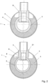
- Fig. 2 shows a sectional view through a pre-insulated pipeline 1 with a cylindrical branch pipe, which is known from the prior art.
- the aim is to demonstrate the effect of the eccentricity of the connected branch pipe with a cylindrical end or a conical end according to the invention.
- Both variants show the branch pipe with the same offset to the center of the medium pipe 2.
- the end of the branch pipe extends further into the medium pipe and thus creates unwanted resistance. Since it is essential for good stability that the entire surface of the bore surrounds the end of the branch pipe, the branch pipe must be placed so deep otherwise it would not be guaranteed that the branch pipe on the left side would be sufficiently supported by the circumference of the bore and there would be too little material for a good weld.
- the bore 7 is smaller and therefore does not have to extend so far down into the medium pipe 2 in order to be supported by the entire circumference of the bore or so that there is enough material for welding.
- the cone 8 has a cone angle ⁇ between 10 and 45°.
Landscapes
- Engineering & Computer Science (AREA)
- General Engineering & Computer Science (AREA)
- Mechanical Engineering (AREA)
- Branch Pipes, Bends, And The Like (AREA)
- Lining Or Joining Of Plastics Or The Like (AREA)
Description
- Die Erfindung betrifft ein Verfahren und ein System zum Anbringen eines Abzweigrohres aus Kunststoff vorzugsweise für einen Sensoranschluss an einer vorisolierten Rohrleitung, enthaltend ein Mediumrohr, eine Isolationsschicht und ein Mantelrohr, beinhaltend folgende Schritte:
- Freilegen eines bestimmten Bereichs des Mediumrohres durch Heraustrennen und Entfernen eines zylindrischen Bereichs der Isolationsschicht der Rohrleitung, wobei die Mittelachse des herauszutrennenden zylindrischen Bereichs rechtwinklig zur Rohrleitungsachse der vorisolierten Rohrleitung verläuft,
- Durchbohren der Wandung des Mediumrohres im freigelegtem Bereich,
- Erwärmen des entstandenen Bohrungsumfangs im Mediumrohr mittels Heizwerkzeug,
- Erwärmen des Abzweigrohres mittels Heizwerkzeug,
- Einpressen des erwärmten Abzweigrohres in die erwärmte Bohrung.
- Abzweigrohre sind aus dem Stand der Technik bekannt und werden meist für den Anschluss an nicht isolierte Rohrleitungen mittels eines Anbohrsattelstücks oder Anbohr-T-Stücks umgesetzt.
- Bei vorisolierten Rohrleitungen wird in der Regel ein bereits vorfabriziertes und vorisoliertes T-Stück in die Rohrleitung eingebaut, was ein nachträgliches Anbringen eines Abzweigrohres erübrigt. In der Regel sind solche T-Stücke mit demselben oder leicht reduzierten Stutzen als Abgang ausgebildet gegenüber den Anschlüssen an die Hauptleitung und somit meist überdimensioniert für den Anschluss von Sensoren. Zudem muss das vor oder während der Installation eingeplant werden oder wenn dies nachträglich erfolgen soll, muss dazu ein Stück aus der verlegten vorisolierten Rohrleitung entfernt werden und ein solches T-Stück eingesetzt werden.
- Aus der
EP 2 957 812 A2 ist eine isolierte Rohrleitung bekannt an die ein Abzweigrohr angeordnet wird. Wobei dazu die Isolation um das metallische Mediumrohr entfernt wird und anschliessend eine Bohrung ins Mediumrohr eingebracht wird. Das Abzweigrohr wird nun mittels Lichtbogenschweissen am Mediumrohr fixiert. - Die
EP 1 314 539 A1 offenbart eine Vorrichtung zum Anschweissen von Verbindungselementen an Kunststoffrohrleitungswandungen. DieWO2011034417A1 offenbart eine Rohrleitungsbaugruppe zum Verbinden von Verbindungsbaugruppen. Im oben aufgeführten Stand der Technik ist es mehr oder weniger erforderlich, bei bereits vorisolierten Rohrleitungen mit einem Mediumrohr aus Kunststoff ein standard T-Stück einzuplanen und einzubauen, das für Sensorzugänge meist überdimensioniert ist. Oder als Alternative aus den bekannten Systemen, die Verwendung eines metallischen Mediumrohrs und das anzuschliessende Abzweigrohr ebenfalls aus einem metallischen Werkstoff, wobei hier der Nachteil des metallischen Werkstoffs ist und dies in manchen Bereichen aufgrund der Anwendung nicht zulässig ist und auch ein höheres Gewicht und Korrosionsprobleme mit sich bringt. - Es ist Aufgabe der Erfindung ein System und ein damit verbundenes Verfahren vorzuschlagen, das ermöglicht an bereits verlegten, vorisolierte Rohrleitungen mit einem Mediumrohr aus Kunststoff ein Abzweigrohr oder ein Formstück mit rohrförmigen Anschlussbereich aus Kunststoff anzuschliessen, wobei der Anschluss eine genügend hohe Stabilität aufweisen muss. Zudem soll das durchfliessende Medium im Mediumrohr möglichst nicht durch das Abzweigrohr behindert werden wie auch das Anschliessen eines Abzweigrohres einfach durchzuführen sein soll aber dennoch gewährleistet ist, dass die Befestigung den Anforderungen entspricht und neben einer hohen Masshaltigkeit auch eine Reproduzierbarkeit gewährleistet.
- Diese Aufgabe wird erfindungsgemäss durch den Gegenstand des unabhängigen Anspruchs 1 und des unabhängigen Anspruchs 8 gelöst. Gemäss dem Verfahren nach Anspruch 1 erfolgt das Erwärmen des Bohrungsumfangs und das Erwärmen des Abzweigrohres gleichzeitig.
- Zudem ist das Abzweigrohr am mit der Rohrleitung zu verschweissenden Ende konisch ausgebildet und durch Erwärmung mittels Schweisstool am Mediumrohr angeschweisst.
- Das erfindungsgemässe Verfahren zum Anbringen eines Abzweigrohres an einer vorisolierten Rohrleitung, enthaltend ein Mediumrohr aus Kunststoff, eine Isolationsschicht und ein Mantelrohr, beinhaltet die folgenden Schritte. Um das Abzweigrohr am Mediumrohr anschliessen zu können wird das Mediumrohr freigelegt. Dies erfolgt durch ein Heraustrennen des Mantelrohres und der Isolationsschicht, wobei dazu ein zylindrischer Bereich der Isolationsschicht und des darüber angeordneten Mantelrohres abgetrennt und entfernt wird. Die Mittelachse des herauszutrennenden zylindrischen Bereichs verläuft senkrecht bzw. im rechten Winkel zur Mittelachse der vorisolierten Rohrleitung. Um die Rechtwinkligkeit zur Rohrleitung sicherzustellen, kann vorzugsweise mit einer auf die Rohrleitung aufgesetzten Führung gearbeitet werden, die das Trennwerkzeug beim Heraustrennen bzw. Abtrennen des zylindrischen Bereichs führt. Das Heraustrennen bzw. Abtrennen erfolgt vorzugsweise mittels eines Trennwerkzeugs, beispielsweise einer Lochsäge, wodurch eine zylindrische Form aus der Isolationsschicht und dem Mantelrohr abgetrennt wird und mittels eines weiteren Werkzeugs, wie beispielsweise eines Schraubenziehers, kann die Isolationsschicht herausgebrochen werden. Durch das vorhergehende Trennen des zylindrischen Bereichs liegt eine saubere Kontur vor. Anschliessend wird im freigelegten Bereich die Wandung des Mediumrohres durchbohrt. Für das Durchbohren kann mit einem Bohrwerkzeug gearbeitet werden, welches an die Geometrie des zylindrischen Bereichs angepasst ist, damit eine exakte Führung gewährleisten werden kann. Das heisst, vorzugsweise weist das Bohrwerkzeuge einen Bereich auf, der dem Durchmesser des zylindrischen Bereichs entspricht, wodurch das Bohrwerkzeug axial geführt ist. Der entstandene Bohrumfang wird mittels eines Heizwerkzeugs erwärmt, wobei die Form des Heizwerkzeugs vorzugsweise konisch ausgebildet ist. Das anzuschliessende Abzweigrohr wird ebenso mittels eines Heizwerkzeugs erwärmt. Daraufhin wird das Abzweigrohr mit dem erwärmten Ende in die erwärmte Bohrung gepresst und für einige Sekunden so gehalten bis sich die Schweissnaht, die sich gebildet hat etwas verfestigt. Erfindungsgemäss erfolgt das Erwärmen des Umfangs der Bohrung im Mediumrohr und das Erwärmen des Abzweigrohres gleichzeitig.
- Es ist vorteilhaft, wenn das Erwärmen des Umfanges der Bohrung im Mediumrohr und das Ende des Abzweigrohres mit demselben Heizwerkzeug erfolgt. Vorzugsweise weist das Heizwerkzeug dazu zwei Heizkulissen auf, die gleichzeitig erwärmt werden und an denen jeweils der Bohrungsumfang und das Abzweigrohr erwärmt werden.
- Es ist vorteilhaft, wenn das Freilegen mittels eines Trennwerkzeugs erfolgt, wobei das Trennwerkzeug zentrisch geführt wird. Dazu wird vorzugsweise ein zentraler Führungsbohrer zur Zentrierung des Trennwerkzeugs verwendet und gleichzeitig eine Führungsbohrung durch den Rohrleitungsquerschnitt gebildet.
- Es ist vorteilhaft wenn das Durchbohren der Wandung des Mediumrohres zweifach geführt wird, wobei dies mittels der Führungsbohrung und dem Durchmesser des zylindrischen Bereichs erzielt wird. Das Bohrwerkzeug weist vorzugsweise einen zentralen Führungsbohrer auf sowie im oberen Bereich einen Durchmesser, der mit dem Durchmesser des zylindrischen Bereichs fluchtet, wodurch der Bohrvorgang zweifach geführt ist und dadurch eine senkrechte und gerade Ausrichtung zur Mittelachse gewährleistet.
- Als bevorzugte Ausführungsform ist auch der Fügevorgang mit Hilfe des Durchmessers des zylindrischen Bereichs geführt. Dazu fluchtet der Aussendurchmesser der Halterung mit Durchmesser des zylindrischen Bereichs.
- Vorzugsweise erfolgt das Einpressen des Abzweigrohres bis an einen vorgegebenen Anschlag, wobei der Anschlag an der Halterung oder am Abzweigrohr angeordnet ist.
- Als vorteilhaft hat sich auch gezeigt, wenn die Tiefe des herauszutrennenden zylindrischen Bereichs der Isolationsschicht über einen Anschlag am Trennwerkzeug festgelegt wird. Dadurch ist gewährleistet, dass nicht zu tief in das Rohr hineingeschnitten wird um zu vermeiden, dass das Mediumrohr verletzt wird, aber dennoch sichergestellt wird, dass die Isolationsschicht in diesem zylindrischen Bereich bis hin zur Aussenmantelfläche des Mediumrohres entfernt werden kann.
- Gemäss einer bevorzugten Ausführungsform wird das Durchbohren der Wandung des Mediumrohres bis zu einem festgelegten Anschlag durchgeführt. Dadurch wird sichergestellt, dass nicht aus Versehen in die gegenüberliegende Wandung hineingebohrt wird und das Mediumrohr an der Innenmantelfläche verletzt wird.
- Die vorliegende Erfindung offenbart ein System eines Abzweigrohres für einen Sensoranschluss an einer verlegten, vorisolierten Rohrleitung bestehend aus einem Mediumrohr aus Kunststoff, einem Mantelrohr und einer dazwischen angeordneten Isolationsschicht. An der Rohrleitung liegt ein freigelegter zylindrischer Bereich vor, wo die Isolationsschicht und das Mantelrohr entfernt wurden. Der zylindrische Bereich bzw. dessen Mittelachse ist rechtwinklig auf die Mittelachse der Rohrleitung ausgerichtet. Durch die Wandung des Mediumrohres verläuft eine Bohrung konzentrisch zum zylindrischen Bereich. Zudem weist das System ein in der Bohrung angeordnetes Abzweigrohr auf. Das Abzweigrohr ist am zu verschweissenden Ende konisch ausgebildet und mit dem Mediumrohr verschweisst, wobei die Schweissung durch die Erwärmung des Abzweigrohres und die Erwärmung des Umfangs der Bohrung im Mediumrohr mittels Heizwerkzeug durchgeführt wird. Durch die konische Form am Ende des Abzweigrohres ist gewährleistet, dass das Abzweigrohr nur soweit durch die Bohrung ragt, dass der Umfang der Bohrung bzw. dessen Mantelfläche komplett am Abzweigrohr anliegt auch wenn die Bohrung nicht mit der Mittelachse des Mediumrohres fluchtet bzw. nicht zentrisch auf das Mediumrohr ausgerichtet ist. Ein solcher Versatz kann entstehen, wenn das Mantelrohr nicht konzentrisch mit dem Mediumrohr verläuft. Dies kann durchaus der Fall sein bei vorisolierten Rohren. Aufgrund dessen, dass das Abzweigrohr zentrisch auf das Mantelrohr gerichtet ist, was aufgrund des Verfahrens zum Anschliessen des Abzweigrohrs und dem Anbringen des zylindrischen Bereichs erfolgt, kann es sein, dass die Mittelachse der Bohrung versetzt zum Zentrum des Mediumrohres verläuft. Würde hier nun ein zylindrisches Ende eines Abzweigrohres eingebracht werden, müsste das weit in das Mediumrohr hineinragen um sicher zu stellen, dass die komplette Mantelfläche des Bohrumfangs am Abzweigrohr anliegt, da bei einem Versatz auf der einen Seite der Bohrung die Bohrungsmantelfläche tiefer hinunter ragt. Mittels eines Konus als Ende des Abzweigrohres, welcher von der Bohrung aufgenommen wird, ist auch bei einem exzentrischen Versatz gewährleistet, dass das Abzweigrohr nicht tief in das Mediumrohr hineinragt. Aufgrund des Konus weist das Abzweigrohr am Ende einen kleineren Durchmesser auf was eine kleinere Bohrung bedarf. Dennoch bildet die Mantelfläche der Bohrung durch die schräge Kontaktfläche mit dem Konus eine genügend grosse Auflagefläche um die benötigte Stabilität der Verschweissung zu erreichen.
- Vorzugsweise weist der Konus am Ende des Abzweigrohres einen Winkel zwischen 10 bis 45° auf, vorzugsweise 18 bis 35°.
- Vorzugsweise weist das Abzweigrohr einen Anschlag zur Begrenzung des Fügewegs auf, wobei der Anschlag durch eine am Aussendurchmesser des Abzweigrohres angeordnete Schulter gebildet ist oder durch das Ende des Abzweigrohres indem der Anschlag in der Halterung während des Fügens axial begrenzt ist.
- Ein Ausführungsbeispiel der Erfindung wird anhand der Figuren beschrieben, wobei sich die Erfindung nicht nur auf das Ausführungsbeispiel beschränkt. Es zeigen:
- Fig. 1
- den Ablauf des erfindungsgemässen Verfahrens und
- Fig. 2
- einen Schnitt durch ein zylindrisches Abzweigrohr und ein erfindungsgemässes konisches Abzweigrohr.
- Die in
Fig. 1 dargestellte Zeichnung zeigt den Ablauf des erfindungsgemässen Verfahrens schrittweise von A - G. Unter der Abbildung A ist der Querschnitt einer vorisolierten Rohrleitung 1 abgebildet. Daraus ist das Mediumrohr 2 aus Kunststoff, das Mantelrohr 3 und die Isolationsschicht 4 ersichtlich. Vorzugsweise ist auch das Mantelrohr 3 aus einem Kunststoff jedoch sind für das Mantelrohr 3 auch andere Werkstoffe denkbar, beispielsweise metallische Werkstoffe.Abbildung B zeigt das Trennwerkzeug 10, welches zum Freilegen bzw. Heraustrennen oder Abtrennen eines zylindrischen Bereichs 6 in der Isolationsschicht 4 mit dem darüber liegenden Mantelrohr 3 dient, vorzugsweise wird dazu eine Lochsäge eingesetzt. In derAbbildung B ist ersichtlich, dass eine zylindrische Abtrennung 20 erfolgt ist, vorzugsweise wird in der Mitte des Trennwerkzeugs 10 zur Zentrierung ein Führungsbohrer 23 eingesetzt, der gewährleistet, dass der zylindrische Bereich 6 zentrisch im rechten Winkel auf das Mantelrohr 4 gerichtet ist und eine Führungsbohrung 22 für den weiteren Arbeitsschritt herstellt. Ebenso ist es vorteilhaft, wenn das Werkzeug 10 zum Trennen einen Anschlag 11 für die Tiefe aufweist, dadurch wird gewährleistet, dass das Mediumrohr 2 nicht verletzt wird aber dennoch der zylindrische Bereich 6 genügend tief ausgenommen ist, dass das Mediumrohr 2 freigelegt werden kann. In Abbildung C ist der zylindrische Bereich 6 freigelegt, indem die Isolation und ein Teil des Mantelrohrs entfernt wurde, wobei vorzugsweise ein Schraubenzieher als Hilfsmittel eingesetzt wird, um die Isolation herauszubrechen. Die eingeschnittene Nut durch das Trennwerkzeug erlaubt es einen sauberen zylindrischen Bereich 6 zu haben. Anschliessend wird die Wandung des Mediumrohres 2 im freigelegten Bereich 6 durchbohrt, ersichtlich in Abbildung D. Auch dazu wird bevorzugt eine Lochsäge mit kleinerem Durchmesser verwendet, aber auch ein grosser Bohrer wäre denkbar. Das Bohrwerkzeug 13 hat einen Führungsdurchmesser der dem Durchmesser des zylindrischen Bereichs 6 entspricht und mit der zentrischen Führungsbohrung 22 und dem Führungsbohrer 23 bzw. der zweifachen Führung wird gewährleistet, dass ebenfalls ein senkrechtes Anbohren des Mediumrohres möglich ist. Auch hier wird vorzugsweise mit einem Anschlag 14 für die Tiefe gearbeitet, damit gewährleistet ist, dass nicht in die gegenüberliegende Wandung gebohrt wird oder das Mediumrohr an der Innenmantelfläche verletzt wird. Abbildung E zeigt das erfindungsgemässe Verfahren nach dem Erwärmen der Bohrung 7 und dem Abzweigrohr 5. Das Heizwerkzeug 15 weist an einem Ende eine Heizkulisse auf, der als Konus 16 ausgebildet ist mit dem die Bohrung 7 bzw. die Mantelfläche der Bohrung erwärmt wird. In der Abbildung E ist gut ersichtlich, dass das Erwärmen bereits stattgefunden hat, da die zuvor zylindrische Bohrung 7 nun nach dem Anwärmen durch den Konus 16 eine konische Form aufweist. Gleichzeitig wird auf der anderen Seite des Heizwerkzeugs 15 mit der Heizkulisse die als Innenkonus 17 ausgebildet ist, das Abzweigrohr 5 erwärmt bzw. das zu verschweissende Ende des Abzweigrohres 5, welches als Konus 8 ausgebildet ist. - Das Heizwerkzeug ist ebenfalls mit einem Führungsdurchmesser ausgerüstet der ebenfalls am Durchmesser des zylindrischen Bereichs 6 die Ausrichtung zusätzlich gewährleistet. Vorzugsweise ist das Abzweigrohr 5 in einer Halterung 18 angeordnet, die es ermöglicht das Abzweigrohr 5 korrekt am Schweissspiegel 17 zu positionieren. Die Erwärmung der Teile dauert einige Sekunden. Dann wird das Heizwerkzeug 15 entfernt und das Abzweigrohr 5 mithilfe der Halterung 18 in die Bohrung 7 gepresst, was aus Abbildung F zu entnehmen ist. Um eine reproduzierbare Schweissung zu gewährleisten wird das Fügen des Abzweigrohres mit der Bohrung im Mediumsrohr wegbegrenzt durchgeführt. Dazu weist die Halterung 18 in der das Abzweigrohr 5 zum Erwärmen und Fügen angeordnet ist vorzugsweise einen Anschlag 19 auf, dieser begrenzt den Fügeweg, wodurch die Anpresskraft nicht limitiert ist und jede Schweissung gleich ausfällt, egal von welchem Installateur ausgeführt. Zudem ist es vorteilhaft wenn ein Anschlag 21 auch direkt am Abzweigrohr angeordnet ist um den Fügeweg zu begrenzen. Dazu wird der Anschlag 21, welcher vorzugsweise durch das Abzweigrohrende gebildet wird oder alternativ durch eine Schulter wie in
Fig. 2 dargestellt, axial begrenzt indem der Anschlag in der Halterung ansteht. Des Weiteren dient die Halterung 18 auch der Führung und weist vorzugsweise einen Aussendurchmesser auf, der mit dem Durchmesser des zylindrischen Bereichs 6 korreliert, wodurch die Halterung 18 beim Anpressen geführt ist. In Abbildung G ist das fertig verschweisste System eines Abzweigrohrs 5 für einen Sensoranschluss ersichtlich. -
Fig. 2 zeigt eine Schnittansicht durch eine vorisolierte Rohrleitung 1 mit einem zylindrischen Abzweigrohr, was aus dem Stand der Technik bekannt ist. InFig. 2 soll der Effekt der Exzentrizität des angeschlossenen Abzweigrohrs mit zylindrischem Ende oder einem erfindungsgemässen konischen Ende aufgezeigt werden. - Beide Varianten zeigen das Abzweigrohr mit demselben Versatz zur Mitte des Mediumrohres 2. Bei der oberen Abbildung mit zylindrischem Ende ist deutlich ersichtlich, dass das Ende des Abzweigrohres weiter in das Mediumrohr hineinragt und so einen ungewollten Widerstand bildet. Da es zwingend für eine gute Stabilität ist, dass die komplette Mantelfläche der Bohrung das Ende des Abzweigrohres umgibt, muss das Abzweigrohr so tief platziert werden ansonsten wäre nicht gewährleistet, dass das Abzweigrohr auf der linken Seite genügend vom Bohrungsumfang gestützt ist wie auch zu wenig Material für eine gute Verschweissung vorliegen würde.
- Hingegen bei der erfindungsgemässen Lösung mit einem Konus 8 am Ende des Abzweigrohres 5 fällt die Bohrung 7 kleiner aus und muss dadurch auch nicht so weit nach unten in das Medimrohr 2 ragen um vom kompletten Bohrungsumfang gestützt zu werden bzw. damit genügend Material für eine Schweissung vorliegt. Der Konus 8 weist einen Konuswinkel α zwischen 10 und 45° auf.
-
- 1
- Rohrleitung
- 2
- Mediumrohr
- 3
- Mantelrohr
- 4
- Isolationsschicht
- 5
- Abzweigrohr
- 6
- zylindrischer Bereich
- 7
- Bohrung
- 8
- Konus Abzweigrohr
- 9
- zylindrischer Abzweigrohr Stand der Technik
- 10
- Trennwerkzeug
- 11
- Tiefenanschlag Trennwerkzeug
- 12
- Schraubenzieher
- 13
- Bohrwerkzeug
- 14
- Anschlag Bohrwerkzeug
- 15
- Heizwerkzeug
- 16
- Konus-Heizkulisse
- 17
- Innenkonus-Heizkulisse
- 18
- Halterung
- 19
- Anschlag Halterung
- 20
- zylindrische Abtrennung
- 21
- Anschlag am Abzweigrohr
- 22
- Führungsbohrung
- 23
- Führungsbohrer
Claims (11)
- Verfahren zum Anbringen eines Abzweigrohres (5) aus Kunststoff an einer vorisolierten Rohrleitung (1) enthaltend ein Mediumrohr (2) aus Kunststoff, eine Isolationsschicht (4) und ein Mantelrohr (3), wobei das Abzweigrohr (5) an dessen mit der Rohrleitung (1) zu verschweissendem Ende (8) konisch ausgebildet ist, beinhaltend folgende Schritte:• Freilegen eines bestimmten Bereichs des Mediumrohres (2) durch Heraustrennen und Entfernen eines zylindrischen Bereichs (6) des Mantelrohres (2) und der Isolationsschicht (4) der Rohrleitung (1), wobei die Mittelachse des herauszutrennenden zylindrischen Bereichs (6) rechtwinklig zur Rohrleitungsachse der vorisolierten Rohrleitung (1) verläuft,• Durchbohren der Wandung des Mediumrohres (2) im freigelegtem Bereich,• Erwärmen des entstandenen Bohrungsumfangs (7) im Mediumrohr (2) mittels Heizwerkzeug (15),• Erwärmen des Abzweigrohres mittels Heizwerkzeug (15),• Einpressen des erwärmten Abzweigrohres (5) in die erwärmte Bohrung (7),wobei das Erwärmen des Bohrungsumfangs (7) und das Erwärmen des Abzweigrohres (5) gleichzeitig erfolgt.
- Verfahren nach Anspruch 1, dadurch gekennzeichnet, dass das Erwärmen des Bohrungsumfangs (7) und das Erwärmen des Abzweigrohres (5) mit demselben Heizwerkzeug (15) erfolgt.
- Verfahren nach einem der Ansprüche 1 oder 2, dadurch gekennzeichnet, dass das Freilegen mittels eines Trennwerkzeugs (10) erfolgt, wobei das Trennwerkzeug (10) zentrisch geführt wird.
- Verfahren nach einem der Ansprüche 1 bis 3, dadurch gekennzeichnet, dass das Durchbohren der Wandung des Mediumsrohres (2) zweifach geführt wird.
- Verfahren nach einem der Ansprüche 1 bis 4, dadurch gekennzeichnet, dass das Einpressen des erwärmten Abzweigrohres (2) bis an einen vorgegebenen Anschlag (19, 21) erfolgt.
- Verfahren nach einem der Ansprüche 1 bis 5, dadurch gekennzeichnet, dass die Tiefe des herauszutrennenden zylindrischen Bereichs (6) über einen Anschlag (11) am Trennwerkzeug (10) festgelegt wird.
- Verfahren nach einem der Ansprüche 1 bis 6, dadurch gekennzeichnet, dass das Durchbohren der Wandung des Mediumsrohres (2) bis zu einem festgelegten Anschlag (14) erfolgt.
- System mit einem Abzweigrohr (5) aus Kunststoff und einer vorisolierten Rohrleitung (1), bestehend aus einem Mediumrohr (2) aus Kunststoff, einem Mantelrohr (3) und einer dazwischen angeordneten Isolationsschicht (4), wobei das Abzweigrohr (5) vorzugsweise für einen Sensoranschluss an einer verlegten, vorisolierten Rohrleitung (1) ist, wobei ein freigelegter zylindrischer Bereich (6) im Mantelrohr (3) und in der Isolationsschicht (4) vorliegt, wobei die Mittelachse des zylindrischen Bereichs (6) rechtwinklig zur Mittelachse der vorisolierten Rohrleitung (1) verläuft und eine konzentrisch zur Mittelachse des zylindrischen Bereichs (6) angeordnete Bohrung (7) durch die Wandung des Mediumrohres (2) verläuft, wobei das Abzweigrohr (5) in der Bohrung (7) angeordnet ist, wobei das Abzweigrohr (5) an dessen mit der Rohrleitung (1) zu verschweissenden Ende (8) konisch ausgebildet ist und durch Erwärmung mittels Heizwerkzeug (15) am Mediumrohr angeschweisst ist.
- System nach Anspruch 8, dadurch gekennzeichnet, dass der Konus am Ende (8) des Abzweigrohres (5) zwischen 105 bis 45° aufweist, vorzugsweise 18 bis 35°.
- System nach einem der Ansprüche 8 oder 9, dadurch gekennzeichnet, dass am Abzweigrohr (2) einen Anschlag (21) zur Begrenzung des Fügewegs angeordnet ist.
- System nach Anspruch 10, dadurch gekennzeichnet, dass der Anschlag (21) durch das Abzweigrohrende oder eine Schulter gebildet wird.
Priority Applications (4)
| Application Number | Priority Date | Filing Date | Title |
|---|---|---|---|
| PL20212814.6T PL4012240T3 (pl) | 2020-12-09 | 2020-12-09 | Rura odgałęźna do przyłącza czujnika |
| EP20212814.6A EP4012240B1 (de) | 2020-12-09 | 2020-12-09 | Abzweigrohr für sensoranschluss |
| ES20212814T ES2991832T3 (es) | 2020-12-09 | 2020-12-09 | Tubo de derivación para conexión de sensor |
| HUE20212814A HUE069564T2 (hu) | 2020-12-09 | 2020-12-09 | Csõelágazás érzékelõcsatlakozáshoz |
Applications Claiming Priority (1)
| Application Number | Priority Date | Filing Date | Title |
|---|---|---|---|
| EP20212814.6A EP4012240B1 (de) | 2020-12-09 | 2020-12-09 | Abzweigrohr für sensoranschluss |
Publications (3)
| Publication Number | Publication Date |
|---|---|
| EP4012240A1 EP4012240A1 (de) | 2022-06-15 |
| EP4012240C0 EP4012240C0 (de) | 2024-09-25 |
| EP4012240B1 true EP4012240B1 (de) | 2024-09-25 |
Family
ID=73789970
Family Applications (1)
| Application Number | Title | Priority Date | Filing Date |
|---|---|---|---|
| EP20212814.6A Active EP4012240B1 (de) | 2020-12-09 | 2020-12-09 | Abzweigrohr für sensoranschluss |
Country Status (4)
| Country | Link |
|---|---|
| EP (1) | EP4012240B1 (de) |
| ES (1) | ES2991832T3 (de) |
| HU (1) | HUE069564T2 (de) |
| PL (1) | PL4012240T3 (de) |
Family Cites Families (6)
| Publication number | Priority date | Publication date | Assignee | Title |
|---|---|---|---|---|
| JPH01196546A (ja) * | 1988-02-01 | 1989-08-08 | Fuji Tekomu Kk | 配管の内部調査方法及びその装置 |
| ITPD20010110U1 (it) * | 2001-11-27 | 2003-05-27 | Ritmo Spa | Dispositivo perfezionato per la saldatura termica di raccordi sulla parete di tubi in materia plastica |
| NL2003496C2 (nl) * | 2009-09-15 | 2011-03-16 | Thermaflex Internat Holding B V | Leidingsamenstel. |
| DE102013015038A1 (de) * | 2013-09-12 | 2015-03-12 | Endress + Hauser Flowtec Ag | Messrohr für ein Durchflussmessgerät und Durchflussmessgerät |
| DK178155B1 (en) | 2014-06-16 | 2015-07-06 | Pipeteq Systems As | A process for producing a branch on a pre-insulated pipe |
| DE102018129506A1 (de) * | 2018-11-23 | 2020-05-28 | Eberspächer Exhaust Technology GmbH & Co. KG | Verfahren zur Herstellung einer Abgasanlage |
-
2020
- 2020-12-09 EP EP20212814.6A patent/EP4012240B1/de active Active
- 2020-12-09 PL PL20212814.6T patent/PL4012240T3/pl unknown
- 2020-12-09 HU HUE20212814A patent/HUE069564T2/hu unknown
- 2020-12-09 ES ES20212814T patent/ES2991832T3/es active Active
Also Published As
| Publication number | Publication date |
|---|---|
| EP4012240C0 (de) | 2024-09-25 |
| HUE069564T2 (hu) | 2025-03-28 |
| PL4012240T3 (pl) | 2025-02-24 |
| EP4012240A1 (de) | 2022-06-15 |
| ES2991832T3 (es) | 2024-12-05 |
Similar Documents
| Publication | Publication Date | Title |
|---|---|---|
| EP0170844B1 (de) | Anbohrformstück aus schweissbarem Kunstoff | |
| EP0140060B1 (de) | Dichtungsring für Rohrverbindungen | |
| EP0272511A2 (de) | Verfahren zur Herstellung von Rohrverbindungen für Hochdruckhydraulikleitungen | |
| EP1305154B1 (de) | Vorrichtung zum verbinden von bauteilen aus schmelzbarem kunststoff | |
| DE3874216T2 (de) | Rohrleitungssystem. | |
| DE102007002606A1 (de) | Sondenfuß für eine Erdwärmesonde | |
| EP4012240B1 (de) | Abzweigrohr für sensoranschluss | |
| EP0921875A1 (de) | Vorrichtung und verfahren zum verbinden eines ersten rohres mit einem rohrförmigen element sowie verbindung zwischen einem ersten rohr und einem rohrförmigen element | |
| DE7827573U1 (de) | Schalldämpfer für Luftleitungen, insbesondere für Klimaanlagen | |
| EP3298316B1 (de) | Flanschverbindung für bauteile aus kunststoff, insbesondere für rohrförmige bauteile aus kunststoff | |
| DE1964719A1 (de) | Rohranschlussstueck oder -armatur fuer Kunststoffrohre | |
| DE3715184A1 (de) | Verbindungsanordnung | |
| EP0204145A1 (de) | Verbindungsteil zum Verschweissen von Rohren | |
| DE19933977C2 (de) | Verfahren zum Anbinden eines Anschlußrohres an ein mittels eines Reliningrohres aus Kunststoffmaterial saniertes Hauptrohr | |
| DE4136349C2 (de) | Schweißvorrichtung für Kunststoffrohre | |
| EP1927806A1 (de) | Vorrichtung zur Verbindung zweier Rohre | |
| DE3600156A1 (de) | Verfahren zur herstellung einer schweissverbindung zwischen kunststoffrohren, mittel zur durchfuehrung dieses verfahrens und rohrverbindung | |
| EP4015887A1 (de) | Verbindungselement für eine rohranordnung und anordnung | |
| EP3371866B1 (de) | Verfahren zur herstellung einer gasisolierten elektrischen energieübertragungsleitung | |
| EP0445902A1 (de) | Wärmeisoliertes Leitungsrohr | |
| DE29822752U1 (de) | Nichtlösbare Rohrverbindung | |
| DE102011107450A1 (de) | Vorrichtung und Verfahren zum Umformen eines Rohrs | |
| DE2612661B1 (de) | Abzweig zum anschweissen von rohren an einen sammler | |
| EP1342519A1 (de) | Vorrichtung zum Abmanteln eines ummantelten Leitungsrohres | |
| EP1048885B1 (de) | Vorrichtung zur Herstellung einer Verbindung einer Armatur mit einem Rohr |
Legal Events
| Date | Code | Title | Description |
|---|---|---|---|
| PUAI | Public reference made under article 153(3) epc to a published international application that has entered the european phase |
Free format text: ORIGINAL CODE: 0009012 |
|
| STAA | Information on the status of an ep patent application or granted ep patent |
Free format text: STATUS: THE APPLICATION HAS BEEN PUBLISHED |
|
| AK | Designated contracting states |
Kind code of ref document: A1 Designated state(s): AL AT BE BG CH CY CZ DE DK EE ES FI FR GB GR HR HU IE IS IT LI LT LU LV MC MK MT NL NO PL PT RO RS SE SI SK SM TR |
|
| STAA | Information on the status of an ep patent application or granted ep patent |
Free format text: STATUS: REQUEST FOR EXAMINATION WAS MADE |
|
| 17P | Request for examination filed |
Effective date: 20221130 |
|
| RBV | Designated contracting states (corrected) |
Designated state(s): AL AT BE BG CH CY CZ DE DK EE ES FI FR GB GR HR HU IE IS IT LI LT LU LV MC MK MT NL NO PL PT RO RS SE SI SK SM TR |
|
| P01 | Opt-out of the competence of the unified patent court (upc) registered |
Effective date: 20230529 |
|
| STAA | Information on the status of an ep patent application or granted ep patent |
Free format text: STATUS: EXAMINATION IS IN PROGRESS |
|
| 17Q | First examination report despatched |
Effective date: 20240104 |
|
| GRAP | Despatch of communication of intention to grant a patent |
Free format text: ORIGINAL CODE: EPIDOSNIGR1 |
|
| STAA | Information on the status of an ep patent application or granted ep patent |
Free format text: STATUS: GRANT OF PATENT IS INTENDED |
|
| INTG | Intention to grant announced |
Effective date: 20240513 |
|
| P04 | Withdrawal of opt-out of the competence of the unified patent court (upc) registered |
Free format text: CASE NUMBER: APP_39657/2024 Effective date: 20240703 |
|
| GRAS | Grant fee paid |
Free format text: ORIGINAL CODE: EPIDOSNIGR3 |
|
| GRAA | (expected) grant |
Free format text: ORIGINAL CODE: 0009210 |
|
| STAA | Information on the status of an ep patent application or granted ep patent |
Free format text: STATUS: THE PATENT HAS BEEN GRANTED |
|
| AK | Designated contracting states |
Kind code of ref document: B1 Designated state(s): AL AT BE BG CH CY CZ DE DK EE ES FI FR GB GR HR HU IE IS IT LI LT LU LV MC MK MT NL NO PL PT RO RS SE SI SK SM TR |
|
| REG | Reference to a national code |
Ref country code: GB Ref legal event code: FG4D Free format text: NOT ENGLISH |
|
| REG | Reference to a national code |
Ref country code: CH Ref legal event code: EP |
|
| REG | Reference to a national code |
Ref country code: DE Ref legal event code: R096 Ref document number: 502020009319 Country of ref document: DE |
|
| REG | Reference to a national code |
Ref country code: IE Ref legal event code: FG4D Free format text: LANGUAGE OF EP DOCUMENT: GERMAN |
|
| U01 | Request for unitary effect filed |
Effective date: 20240925 |
|
| U07 | Unitary effect registered |
Designated state(s): AT BE BG DE DK EE FI FR IT LT LU LV MT NL PT RO SE SI Effective date: 20241001 |
|
| REG | Reference to a national code |
Ref country code: ES Ref legal event code: FG2A Ref document number: 2991832 Country of ref document: ES Kind code of ref document: T3 Effective date: 20241205 |
|
| PGFP | Annual fee paid to national office [announced via postgrant information from national office to epo] |
Ref country code: NO Payment date: 20241227 Year of fee payment: 5 Ref country code: MC Payment date: 20241226 Year of fee payment: 5 |
|
| PG25 | Lapsed in a contracting state [announced via postgrant information from national office to epo] |
Ref country code: GR Free format text: LAPSE BECAUSE OF FAILURE TO SUBMIT A TRANSLATION OF THE DESCRIPTION OR TO PAY THE FEE WITHIN THE PRESCRIBED TIME-LIMIT Effective date: 20241226 |
|
| PGFP | Annual fee paid to national office [announced via postgrant information from national office to epo] |
Ref country code: GB Payment date: 20241227 Year of fee payment: 5 |
|
| PGFP | Annual fee paid to national office [announced via postgrant information from national office to epo] |
Ref country code: CZ Payment date: 20241202 Year of fee payment: 5 Ref country code: IE Payment date: 20241223 Year of fee payment: 5 |
|
| PG25 | Lapsed in a contracting state [announced via postgrant information from national office to epo] |
Ref country code: RS Free format text: LAPSE BECAUSE OF FAILURE TO SUBMIT A TRANSLATION OF THE DESCRIPTION OR TO PAY THE FEE WITHIN THE PRESCRIBED TIME-LIMIT Effective date: 20241225 |
|
| PG25 | Lapsed in a contracting state [announced via postgrant information from national office to epo] |
Ref country code: RS Free format text: LAPSE BECAUSE OF FAILURE TO SUBMIT A TRANSLATION OF THE DESCRIPTION OR TO PAY THE FEE WITHIN THE PRESCRIBED TIME-LIMIT Effective date: 20241225 Ref country code: GR Free format text: LAPSE BECAUSE OF FAILURE TO SUBMIT A TRANSLATION OF THE DESCRIPTION OR TO PAY THE FEE WITHIN THE PRESCRIBED TIME-LIMIT Effective date: 20241226 |
|
| U20 | Renewal fee for the european patent with unitary effect paid |
Year of fee payment: 5 Effective date: 20241227 |
|
| PGFP | Annual fee paid to national office [announced via postgrant information from national office to epo] |
Ref country code: HU Payment date: 20241220 Year of fee payment: 5 |
|
| REG | Reference to a national code |
Ref country code: HU Ref legal event code: AG4A Ref document number: E069564 Country of ref document: HU |
|
| PG25 | Lapsed in a contracting state [announced via postgrant information from national office to epo] |
Ref country code: IS Free format text: LAPSE BECAUSE OF FAILURE TO SUBMIT A TRANSLATION OF THE DESCRIPTION OR TO PAY THE FEE WITHIN THE PRESCRIBED TIME-LIMIT Effective date: 20250125 |
|
| PG25 | Lapsed in a contracting state [announced via postgrant information from national office to epo] |
Ref country code: SM Free format text: LAPSE BECAUSE OF FAILURE TO SUBMIT A TRANSLATION OF THE DESCRIPTION OR TO PAY THE FEE WITHIN THE PRESCRIBED TIME-LIMIT Effective date: 20240925 |
|
| PGFP | Annual fee paid to national office [announced via postgrant information from national office to epo] |
Ref country code: ES Payment date: 20250131 Year of fee payment: 5 |
|
| PGFP | Annual fee paid to national office [announced via postgrant information from national office to epo] |
Ref country code: CH Payment date: 20250101 Year of fee payment: 5 |
|
| PGFP | Annual fee paid to national office [announced via postgrant information from national office to epo] |
Ref country code: PL Payment date: 20241128 Year of fee payment: 5 |
|
| PG25 | Lapsed in a contracting state [announced via postgrant information from national office to epo] |
Ref country code: SK Free format text: LAPSE BECAUSE OF FAILURE TO SUBMIT A TRANSLATION OF THE DESCRIPTION OR TO PAY THE FEE WITHIN THE PRESCRIBED TIME-LIMIT Effective date: 20240925 |
|
| PLBE | No opposition filed within time limit |
Free format text: ORIGINAL CODE: 0009261 |
|
| STAA | Information on the status of an ep patent application or granted ep patent |
Free format text: STATUS: NO OPPOSITION FILED WITHIN TIME LIMIT |
|
| 26N | No opposition filed |
Effective date: 20250626 |