EP2957812A2 - A process for producing a branch on a pre-insulated pipe - Google Patents
A process for producing a branch on a pre-insulated pipe Download PDFInfo
- Publication number
- EP2957812A2 EP2957812A2 EP15388002.6A EP15388002A EP2957812A2 EP 2957812 A2 EP2957812 A2 EP 2957812A2 EP 15388002 A EP15388002 A EP 15388002A EP 2957812 A2 EP2957812 A2 EP 2957812A2
- Authority
- EP
- European Patent Office
- Prior art keywords
- pipe
- medium conveying
- insulated
- hole
- branch pipe
- Prior art date
- Legal status (The legal status is an assumption and is not a legal conclusion. Google has not performed a legal analysis and makes no representation as to the accuracy of the status listed.)
- Withdrawn
Links
- 238000000034 method Methods 0.000 title claims abstract description 49
- 239000011810 insulating material Substances 0.000 claims description 38
- 229910052751 metal Inorganic materials 0.000 claims description 28
- 239000002184 metal Substances 0.000 claims description 28
- 238000003466 welding Methods 0.000 claims description 22
- 239000012774 insulation material Substances 0.000 claims description 20
- 238000009413 insulation Methods 0.000 claims description 18
- 239000006260 foam Substances 0.000 claims description 9
- 239000012530 fluid Substances 0.000 claims description 8
- 230000004888 barrier function Effects 0.000 claims description 3
- 238000009792 diffusion process Methods 0.000 claims description 3
- 239000011888 foil Substances 0.000 claims description 3
- 238000004519 manufacturing process Methods 0.000 claims description 3
- 238000005187 foaming Methods 0.000 description 8
- 239000000203 mixture Substances 0.000 description 8
- 239000007789 gas Substances 0.000 description 7
- WFKWXMTUELFFGS-UHFFFAOYSA-N tungsten Chemical compound [W] WFKWXMTUELFFGS-UHFFFAOYSA-N 0.000 description 5
- 229910052721 tungsten Inorganic materials 0.000 description 5
- 239000010937 tungsten Substances 0.000 description 5
- XKRFYHLGVUSROY-UHFFFAOYSA-N Argon Chemical compound [Ar] XKRFYHLGVUSROY-UHFFFAOYSA-N 0.000 description 4
- CURLTUGMZLYLDI-UHFFFAOYSA-N Carbon dioxide Chemical compound O=C=O CURLTUGMZLYLDI-UHFFFAOYSA-N 0.000 description 4
- 238000009826 distribution Methods 0.000 description 4
- 239000011261 inert gas Substances 0.000 description 4
- 238000005259 measurement Methods 0.000 description 4
- 229920002635 polyurethane Polymers 0.000 description 4
- 239000004814 polyurethane Substances 0.000 description 4
- 238000010438 heat treatment Methods 0.000 description 3
- 239000004033 plastic Substances 0.000 description 3
- 229920003023 plastic Polymers 0.000 description 3
- 229920005830 Polyurethane Foam Polymers 0.000 description 2
- 229910052786 argon Inorganic materials 0.000 description 2
- 229910002092 carbon dioxide Inorganic materials 0.000 description 2
- 239000001569 carbon dioxide Substances 0.000 description 2
- 238000011109 contamination Methods 0.000 description 2
- 239000001307 helium Substances 0.000 description 2
- 229910052734 helium Inorganic materials 0.000 description 2
- SWQJXJOGLNCZEY-UHFFFAOYSA-N helium atom Chemical compound [He] SWQJXJOGLNCZEY-UHFFFAOYSA-N 0.000 description 2
- 239000007788 liquid Substances 0.000 description 2
- 239000000463 material Substances 0.000 description 2
- 239000011496 polyurethane foam Substances 0.000 description 2
- 230000002787 reinforcement Effects 0.000 description 2
- 238000004891 communication Methods 0.000 description 1
- 238000001816 cooling Methods 0.000 description 1
- 239000000945 filler Substances 0.000 description 1
- 238000009472 formulation Methods 0.000 description 1
- 239000012948 isocyanate Substances 0.000 description 1
- 150000002513 isocyanates Chemical class 0.000 description 1
- 229920005862 polyol Polymers 0.000 description 1
- 150000003077 polyols Chemical class 0.000 description 1
Images


Classifications
-
- F—MECHANICAL ENGINEERING; LIGHTING; HEATING; WEAPONS; BLASTING
- F16—ENGINEERING ELEMENTS AND UNITS; GENERAL MEASURES FOR PRODUCING AND MAINTAINING EFFECTIVE FUNCTIONING OF MACHINES OR INSTALLATIONS; THERMAL INSULATION IN GENERAL
- F16L—PIPES; JOINTS OR FITTINGS FOR PIPES; SUPPORTS FOR PIPES, CABLES OR PROTECTIVE TUBING; MEANS FOR THERMAL INSULATION IN GENERAL
- F16L59/00—Thermal insulation in general
- F16L59/14—Arrangements for the insulation of pipes or pipe systems
- F16L59/16—Arrangements specially adapted to local requirements at flanges, junctions, valves or the like
- F16L59/163—Branch units; Insulation forming a whole with branches
-
- B—PERFORMING OPERATIONS; TRANSPORTING
- B23—MACHINE TOOLS; METAL-WORKING NOT OTHERWISE PROVIDED FOR
- B23K—SOLDERING OR UNSOLDERING; WELDING; CLADDING OR PLATING BY SOLDERING OR WELDING; CUTTING BY APPLYING HEAT LOCALLY, e.g. FLAME CUTTING; WORKING BY LASER BEAM
- B23K9/00—Arc welding or cutting
- B23K9/0026—Arc welding or cutting specially adapted for particular articles or work
-
- B—PERFORMING OPERATIONS; TRANSPORTING
- B23—MACHINE TOOLS; METAL-WORKING NOT OTHERWISE PROVIDED FOR
- B23K—SOLDERING OR UNSOLDERING; WELDING; CLADDING OR PLATING BY SOLDERING OR WELDING; CUTTING BY APPLYING HEAT LOCALLY, e.g. FLAME CUTTING; WORKING BY LASER BEAM
- B23K9/00—Arc welding or cutting
- B23K9/02—Seam welding; Backing means; Inserts
- B23K9/032—Seam welding; Backing means; Inserts for three-dimensional seams
-
- B—PERFORMING OPERATIONS; TRANSPORTING
- B23—MACHINE TOOLS; METAL-WORKING NOT OTHERWISE PROVIDED FOR
- B23K—SOLDERING OR UNSOLDERING; WELDING; CLADDING OR PLATING BY SOLDERING OR WELDING; CUTTING BY APPLYING HEAT LOCALLY, e.g. FLAME CUTTING; WORKING BY LASER BEAM
- B23K9/00—Arc welding or cutting
- B23K9/16—Arc welding or cutting making use of shielding gas
- B23K9/167—Arc welding or cutting making use of shielding gas and of a non-consumable electrode
-
- F—MECHANICAL ENGINEERING; LIGHTING; HEATING; WEAPONS; BLASTING
- F16—ENGINEERING ELEMENTS AND UNITS; GENERAL MEASURES FOR PRODUCING AND MAINTAINING EFFECTIVE FUNCTIONING OF MACHINES OR INSTALLATIONS; THERMAL INSULATION IN GENERAL
- F16L—PIPES; JOINTS OR FITTINGS FOR PIPES; SUPPORTS FOR PIPES, CABLES OR PROTECTIVE TUBING; MEANS FOR THERMAL INSULATION IN GENERAL
- F16L13/00—Non-disconnectable pipe joints, e.g. soldered, adhesive, or caulked joints
- F16L13/02—Welded joints
- F16L13/0254—Welded joints the pipes having an internal or external coating
- F16L13/0272—Welded joints the pipes having an internal or external coating having an external coating
-
- F—MECHANICAL ENGINEERING; LIGHTING; HEATING; WEAPONS; BLASTING
- F16—ENGINEERING ELEMENTS AND UNITS; GENERAL MEASURES FOR PRODUCING AND MAINTAINING EFFECTIVE FUNCTIONING OF MACHINES OR INSTALLATIONS; THERMAL INSULATION IN GENERAL
- F16L—PIPES; JOINTS OR FITTINGS FOR PIPES; SUPPORTS FOR PIPES, CABLES OR PROTECTIVE TUBING; MEANS FOR THERMAL INSULATION IN GENERAL
- F16L41/00—Branching pipes; Joining pipes to walls
- F16L41/08—Joining pipes to walls or pipes, the joined pipe axis being perpendicular to the plane of a wall or to the axis of another pipe
- F16L41/082—Non-disconnectable joints, e.g. soldered, adhesive or caulked joints
- F16L41/084—Soldered joints
-
- B—PERFORMING OPERATIONS; TRANSPORTING
- B23—MACHINE TOOLS; METAL-WORKING NOT OTHERWISE PROVIDED FOR
- B23K—SOLDERING OR UNSOLDERING; WELDING; CLADDING OR PLATING BY SOLDERING OR WELDING; CUTTING BY APPLYING HEAT LOCALLY, e.g. FLAME CUTTING; WORKING BY LASER BEAM
- B23K2101/00—Articles made by soldering, welding or cutting
- B23K2101/04—Tubular or hollow articles
- B23K2101/06—Tubes
-
- F—MECHANICAL ENGINEERING; LIGHTING; HEATING; WEAPONS; BLASTING
- F16—ENGINEERING ELEMENTS AND UNITS; GENERAL MEASURES FOR PRODUCING AND MAINTAINING EFFECTIVE FUNCTIONING OF MACHINES OR INSTALLATIONS; THERMAL INSULATION IN GENERAL
- F16L—PIPES; JOINTS OR FITTINGS FOR PIPES; SUPPORTS FOR PIPES, CABLES OR PROTECTIVE TUBING; MEANS FOR THERMAL INSULATION IN GENERAL
- F16L59/00—Thermal insulation in general
- F16L59/14—Arrangements for the insulation of pipes or pipe systems
- F16L59/143—Pre-insulated pipes
-
- F—MECHANICAL ENGINEERING; LIGHTING; HEATING; WEAPONS; BLASTING
- F16—ENGINEERING ELEMENTS AND UNITS; GENERAL MEASURES FOR PRODUCING AND MAINTAINING EFFECTIVE FUNCTIONING OF MACHINES OR INSTALLATIONS; THERMAL INSULATION IN GENERAL
- F16L—PIPES; JOINTS OR FITTINGS FOR PIPES; SUPPORTS FOR PIPES, CABLES OR PROTECTIVE TUBING; MEANS FOR THERMAL INSULATION IN GENERAL
- F16L59/00—Thermal insulation in general
- F16L59/14—Arrangements for the insulation of pipes or pipe systems
- F16L59/16—Arrangements specially adapted to local requirements at flanges, junctions, valves or the like
- F16L59/18—Arrangements specially adapted to local requirements at flanges, junctions, valves or the like adapted for joints
- F16L59/20—Arrangements specially adapted to local requirements at flanges, junctions, valves or the like adapted for joints for non-disconnectable joints
Definitions
- the present invention relates to insulated medium conveying pipes. More specifically, the present invention relates to a process for producing a branch on a pre-insulated pipe, and to insulated branched medium conveying pipes obtainable by the process.
- One aspect relates to a process for producing a T-branch on a pre-insulated pipe comprising:
- Another aspect relates to a process for producing an insulated branched medium conveying pipe comprising:
- Yet another aspect relates to an insulated branched medium conveying pipe obtainable by the process according to the present invention.
- pre-insulated pipes For district heating and cooling solutions in e.g. the oil and gas sector and for solar heating systems, pre-insulated pipes are widely used.
- An assembly of a pre-insulated pipe typically comprises one or more inner pipes (medium conveying pipes) of either metal or plastic, an insulation layer such as polyurethane foam, and a casing pipe (jacket pipe) of metal or plastic.
- Pre-insulated pipes that are continuously manufactured can further comprise a diffusion barrier in the form of e.g. a film or foil arranged between the insulation layer and the casing material.
- Still another aspect relates to the use of a metal collar in the production of insulated branched medium conveying pipes for protecting exposed insulation material during welding.
- the process comprises providing a pre-insulated pipe comprising a medium conveying pipe of metal, an insulating material surrounding at least a part of the length of the medium conveying pipe and a first jacket pipe at least partly surrounding the insulating material.
- a hole is made in the pre-insulated pipe by removing a part of the jacket pipe and the underlying insulating material so as to expose a part of the medium conveying pipe. Thereafter, a hole is made in the exposed part of the medium conveying pipe.
- a branch pipe of metal is provided for attachment to the medium conveying pipe.
- One end (the first end) of the branch pipe is positioned within the hole of the exposed part of the medium conveying pipe, when the diameter of the branch pipe is smaller than the diameter of the hole.
- the diameter of the hole in the exposed part of the medium conveying pipe is at most 2 mm larger than the outer diameter of the branch pipe, such as within the range of 0.001-2 mm larger, e.g. at most 1.5 mm larger, such as within the range of 0.01-1.5 mm larger, e.g. at most 1.0 mm larger, such as within the range of 0.1-1.0 mm larger, e.g. at most 0.5 mm larger, such as within the range of 0.2-0.5 mm larger than the outer diameter of the branch pipe. This is important to obtain a proper fillet welding between the medium conveying pipe and the branch pipe.
- one end (the first end) of the branch pipe is positioned around the opening of the hole of the exposed part of the medium conveying pipe, when the diameter of the branch pipe is larger than the diameter of the hole.
- the process further comprises the step of arch welding the first end of the branch pipe to the exposed part of the medium conveying pipe using an inert (e.g. argon or helium) or semi-inert (such as carbon dioxide) shielding gas, thereby forming a first fillet weld along the entire circumference of the branch pipe.
- an inert e.g. argon or helium
- semi-inert such as carbon dioxide
- Tungsten Inert Gas (TIG) welding is an arc welding process that uses a non-consumable tungsten electrode to produce the weld.
- the weld area is protected from atmospheric contamination by an inert shielding gas, and a filler metal is normally used.
- a constant-current welding power supply produces energy which is conducted across the arc through a column of highly ionized gas and metal vapours known as a plasma.
- the arch welding is tungsten inert gas welding.
- the process further comprises the step of attaching a compensating plate (reinforcement plate) to the exposed part of the medium conveying pipe and along the entire circumference of the branch pipe.
- a compensating plate reinforcement plate
- the process further comprises the step of insulating the branch pipe with an insulating material.
- the process further comprises the step of insulating the branch pipe with an insulating material; and wherein the insulation step comprises:
- the process further comprises the step of insulating the branch pipe with an insulating material; and wherein the insulation step comprises:
- Insulating material in fluid form may be any type known to the skilled person.
- a well-known insulating material in fluid form is based on polyol and isocyanate (a polyurethane foaming mixture).
- the insulating material in fluid form is a polyurethane foaming mixture.
- the insulating material in fluid form may in one or more embodiments be applied by any discontinuous pipe filling technique known within the art.
- Discontinuous pipe filling techniques include the pour rise technique, the top filling technique, the horizontal mid-point filling technique, the pour-pull technique and the lance withdrawal technique.
- the pour rise technique and the top filling technique are preferred.
- the pipe to be filled is placed in an angle to the horizontal position, and the foaming mixture is injected into the cavity between the inner pipe and the outer casing at the bottom respectively at the top of the pipe, after which the foaming reaction occurs inside the cavity.
- Discontinuous pipe filling techniques require a foam formulation with very good flow properties, so that the entire cavity is filled with foam while at the same time achieving an even distribution of foam properties.
- a preformed tubular insulation adapted for application around the branch pipe.
- the inner diameter of a preformed tubular insulation is thereby dependant on the outer diameter of the branch pipe.
- at least a part of the insulating material is a preformed tubular insulation.
- a foaming mixture is injected into the hole in the pre-insulated pipe, and the preformed tubular insulation is mounted subsequently.
- the process further comprises the step of insulating the branch pipe with an insulating material; and wherein the insulation step comprises:
- the diameter of the hole in the pre-insulated pipe is at most 2 mm larger than the outer diameter of the second jacket pipe (the jacket pipe of the insulated branch pipe), such as within the range of 0.001-2 mm larger, e.g. at most 1.5 mm larger, such as within the range of 0.01-1.5 mm larger, e.g. at most 1.0 mm larger, such as within the range of 0.1-1.0 mm larger, e.g. at most 0.5 mm larger, such as within the range of 0.2-0.5 mm larger than the outer diameter of the second jacket pipe.
- This is important to obtain a proper welding between the first jacket pipe (the jacket pipe of the pre-insulated pipe) and the second jacket pipes.
- the diameter ratio between the branch pipe and the medium conveying pipe is at most 0.8. This is in order to fulfil the requirements of European Standard (EN) EN 13941:2009+A1:2010.
- a metal collar for protecting the exposed insulation material in the hole of the pre-insulated pipe may be inserted between the exposed insulation material and the branch pipe.
- the process before arch welding the first end of the branch pipe to the exposed part of the medium conveying pipe, the process further comprises the step of protecting the exposed insulation material in the hole of the pre-insulated pipe by positioning a metal collar between the exposed insulation material and the branch pipe.
- the pre-insulated pipe further comprises a diffusion barrier in the form of e.g. a film or foil arranged between the insulation material and the first jacket pipe.
- a diffusion barrier in the form of e.g. a film or foil arranged between the insulation material and the first jacket pipe.
- the average lambda value is the recognised parameter used when calculating heat loss for pre-insulated pipes.
- the lambda value depends on the temperature. This makes it necessary to carry out measurements at a minimum of three different temperatures. The measurements are carried out on a section of a DN 50/125-140 pre-insulated pipe at least 3 metres long. This section is taken from a 12-metre length of pipe from the normal production line.
- the temperature of the surroundings (ta) is kept constant while the measurements are being carried out.
- the temperature on the casing pipe is measured, when the temperature of the service pipe is constant.
- the lambda value for the three different temperature conditions can then be calculated on the basis of the temperatures of the service pipe, the casing pipe and of the surroundings.
- the lambda value for a pre-insulated district heating pipe is always given by an average temperature in the polyurethane foam at a temperature of 50°C.
- a straight line can be plotted for the calculated lambda values, because the lambda value is directly proportional to the temperature.
- the pre-insulated pipe has an average lambda value of at most 0.025 W/mK, such as within the range of 0.020-0.025 W/mK, e.g. at most 0.024 W/mK, such as within the range of 0.021-0.024 W/mK, e.g. at most 0.022 W/mK.
- the jacket pipe of the pre-insulated pipe and the branch pipe are preferably of the same material in order to connect them properly; and may be of plastic or metal.
- a pre-insulated pipe 100 comprises a medium conveying pipe 102 of metal, an insulating material 104 surrounding the medium conveying pipe 102 (except from the ends), and a jacket pipe 106 surrounding the insulating material 104.
- a hole 108 is made in the pre-insulated pipe 100 by removing a part of the jacket pipe 106 and the underlying insulating material so as to expose a part 110 of the medium conveying pipe 102.
- the hole 108 is made of a size such that a branch pipe 200 and a compensating plate 300 can be welded onto the exposed part 110 of the medium conveying pipe 102.
- a hole 112 is then made in the exposed part 110 of the medium conveying pipe 102, such that the branch pipe 200 can be in liquid communication with the medium conveying pipe 102.
- the first end 202 of the branch pipe 200 is positioned within the hole 112 of the exposed part 110 of the medium conveying pipe 102; and is then attached thereto by Tungsten Inert Gas (TIG) welding, thereby forming a first fillet weld along the entire circumference of the branch pipe 200.
- Tungsten Inert Gas (TIG) welding Tungsten Inert Gas
- a metal collar 600 for protecting the exposed insulation material in the hole 108 of the pre-insulated pipe is inserted between the exposed insulation material and the branch pipe.
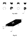
- Figures 4A-B show different views of the metal collar, and its position between the exposed insulation material and the branch pipe is shown in Figure 4C .
- a jacket pipe 400 is positioned around the length of the branch pipe (except the upper end portion) and is then attached to the jacket pipe 106 of the pre-insulated pipe 100 by welding.
- a polyurethane foaming mixture (Component nr. 0700; poseskum 2) is then introduced into the hole 108 of the pre-insulated pipe 100; followed by the mounting of a preformed tubular insulation into said hole and around the branch pipe 200.
Landscapes
- Engineering & Computer Science (AREA)
- Mechanical Engineering (AREA)
- General Engineering & Computer Science (AREA)
- Physics & Mathematics (AREA)
- Plasma & Fusion (AREA)
- Thermal Insulation (AREA)
- Manufacturing Of Electrical Connectors (AREA)
Abstract
Description
- The present invention relates to insulated medium conveying pipes. More specifically, the present invention relates to a process for producing a branch on a pre-insulated pipe, and to insulated branched medium conveying pipes obtainable by the process.
- It is prior known to make insulated branched medium conveying pipes by welding one or more metal branch pipes unto a main metal pipe, building a jacket pipe around the entire structure, and then introducing an insulation material between the metal pipes and the jacket pipe by adding the insulation material in a liquid state, and letting the insulation material expand and solidify through a number of consecutive development stages. However, it is well known that the insulation property is uneven across the length of branched medium conveying pipe. Furthermore, in order to mass produce such insulated T-pipe branches with the above mentioned process; the position of the branch is fixed to specific positions on the medium conveying pipe.
- Hence, there is a need for insulated branched medium conveying pipes that have an even insulation property across the length of the main metal pipe. Furthermore, there is a need for a process for producing such insulated branched medium conveying pipes that is not limited by fixed branch positions on the main metal pipe.
- One aspect relates to a process for producing a T-branch on a pre-insulated pipe comprising:
- providing a pre-insulated pipe comprising a medium conveying pipe of metal, an insulating material surrounding at least a part of the length of the medium conveying pipe and a first jacket pipe at least partly surrounding the insulating material;
- providing a branch pipe of metal, with a first end and a second end;
- making a hole in the pre-insulated pipe by removing a part of the jacket pipe and the underlying insulating material so as to expose a part of the medium conveying pipe;
- making a hole in the exposed part of the medium conveying pipe;
- positioning the first end of the branch pipe within the hole of the exposed part of the medium conveying pipe, or positioning the first end of the branch pipe around the opening of the hole of the exposed part of the medium conveying pipe;
- arch welding the first end of the branch pipe to the exposed part of the medium conveying pipe using an inert or semi-inert shielding gas, thereby forming a first fillet weld along the entire circumference of the branch pipe;
- attaching a compensating plate to the exposed part of the medium conveying pipe and along the entire circumference of the branch pipe; and
- optionally, insulating the branch pipe with an insulating material.
- Another aspect relates to a process for producing an insulated branched medium conveying pipe comprising:
- providing a pre-insulated pipe comprising a medium conveying pipe of metal, an insulating material surrounding at least a part of the length of the medium conveying pipe and a first jacket pipe at least partly surrounding the insulating material;
- providing a branch pipe of metal, with a first end and a second end;
- making a hole in the pre-insulated pipe by removing a part of the jacket pipe and the underlying insulating material so as to expose a part of the medium conveying pipe;
- making a hole in the exposed part of the medium conveying pipe;
- positioning the first end of the branch pipe within the hole of the exposed part of the medium conveying pipe, or positioning the first end of the branch pipe around the opening of the hole of the exposed part of the medium conveying pipe;
- arch welding the first end of the branch pipe to the exposed part of the medium conveying pipe using an inert or semi-inert shielding gas, thereby forming a first fillet weld along the entire circumference of the branch pipe;
- attaching a compensating plate to the exposed part of the medium conveying pipe and along the entire circumference of the branch pipe; and
- optionally, insulating the branch pipe with an insulating material.
- Yet another aspect relates to an insulated branched medium conveying pipe obtainable by the process according to the present invention.
- For district heating and cooling solutions in e.g. the oil and gas sector and for solar heating systems, pre-insulated pipes are widely used. An assembly of a pre-insulated pipe typically comprises one or more inner pipes (medium conveying pipes) of either metal or plastic, an insulation layer such as polyurethane foam, and a casing pipe (jacket pipe) of metal or plastic. Pre-insulated pipes that are continuously manufactured can further comprise a diffusion barrier in the form of e.g. a film or foil arranged between the insulation layer and the casing material.
- Still another aspect relates to the use of a metal collar in the production of insulated branched medium conveying pipes for protecting exposed insulation material during welding.
- Disclosed herein is a process for producing an insulated branched medium conveying pipe. The process comprises providing a pre-insulated pipe comprising a medium conveying pipe of metal, an insulating material surrounding at least a part of the length of the medium conveying pipe and a first jacket pipe at least partly surrounding the insulating material. A hole is made in the pre-insulated pipe by removing a part of the jacket pipe and the underlying insulating material so as to expose a part of the medium conveying pipe. Thereafter, a hole is made in the exposed part of the medium conveying pipe.
- A branch pipe of metal is provided for attachment to the medium conveying pipe. One end (the first end) of the branch pipe is positioned within the hole of the exposed part of the medium conveying pipe, when the diameter of the branch pipe is smaller than the diameter of the hole.
- In one or more embodiments, the diameter of the hole in the exposed part of the medium conveying pipe is at most 2 mm larger than the outer diameter of the branch pipe, such as within the range of 0.001-2 mm larger, e.g. at most 1.5 mm larger, such as within the range of 0.01-1.5 mm larger, e.g. at most 1.0 mm larger, such as within the range of 0.1-1.0 mm larger, e.g. at most 0.5 mm larger, such as within the range of 0.2-0.5 mm larger than the outer diameter of the branch pipe. This is important to obtain a proper fillet welding between the medium conveying pipe and the branch pipe.
- Alternatively, one end (the first end) of the branch pipe is positioned around the opening of the hole of the exposed part of the medium conveying pipe, when the diameter of the branch pipe is larger than the diameter of the hole.
- The process further comprises the step of arch welding the first end of the branch pipe to the exposed part of the medium conveying pipe using an inert (e.g. argon or helium) or semi-inert (such as carbon dioxide) shielding gas, thereby forming a first fillet weld along the entire circumference of the branch pipe. It is important to operate under an inert (e.g. argon or helium) or semi-inert (such as carbon dioxide) shielding gas to avoid damaging the exposed insulation material in the hole of the pre-insulated pipe, as well as to avoid contamination of the welding site.
- Tungsten Inert Gas (TIG) welding is an arc welding process that uses a non-consumable tungsten electrode to produce the weld. The weld area is protected from atmospheric contamination by an inert shielding gas, and a filler metal is normally used. A constant-current welding power supply produces energy which is conducted across the arc through a column of highly ionized gas and metal vapours known as a plasma.
- In one or more embodiments, the arch welding is tungsten inert gas welding.
- In order to avoid that the medium conveying pipe collapses in the vicinity of the branch during use, the process further comprises the step of attaching a compensating plate (reinforcement plate) to the exposed part of the medium conveying pipe and along the entire circumference of the branch pipe. The reinforcement of branched pipes by a compensating plate is further described in European Standard (EN) EN 13941:2009+A1:2010 - hereby incorporated by reference.
- In one or more embodiments, the process further comprises the step of insulating the branch pipe with an insulating material.
- In one or more embodiments, the process further comprises the step of insulating the branch pipe with an insulating material; and wherein the insulation step comprises:
- positioning a second jacket pipe around at least a part of the length of the branch pipe and attaching one end of the second jacket pipe to the first jacket pipe; and
- insulating the hole of the pre-insulated pipe, and the space between the branch pipe and the second jacket pipe with an insulating material.
- In one or more embodiments, the process further comprises the step of insulating the branch pipe with an insulating material; and wherein the insulation step comprises:
- positioning a jacket pipe around at least a part of the length of the branch pipe and attaching one end of the jacket pipe to the jacket pipe of the pre-insulated pipe; and
- insulating the hole of the pre-insulated pipe, and the space between the branch pipe and said jacket pipes with an insulating material.
- Insulating material in fluid form (also known as a foaming mixture) may be any type known to the skilled person. A well-known insulating material in fluid form is based on polyol and isocyanate (a polyurethane foaming mixture).
- In one or more embodiments, the insulating material in fluid form is a polyurethane foaming mixture.
- The insulating material in fluid form may in one or more embodiments be applied by any discontinuous pipe filling technique known within the art. Discontinuous pipe filling techniques include the pour rise technique, the top filling technique, the horizontal mid-point filling technique, the pour-pull technique and the lance withdrawal technique. The pour rise technique and the top filling technique are preferred. In these techniques the pipe to be filled is placed in an angle to the horizontal position, and the foaming mixture is injected into the cavity between the inner pipe and the outer casing at the bottom respectively at the top of the pipe, after which the foaming reaction occurs inside the cavity. Discontinuous pipe filling techniques require a foam formulation with very good flow properties, so that the entire cavity is filled with foam while at the same time achieving an even distribution of foam properties.
- In order to achieve an even distribution of foam around the branch pipe, it may be an advantage to use a preformed tubular insulation adapted for application around the branch pipe. The inner diameter of a preformed tubular insulation is thereby dependant on the outer diameter of the branch pipe. In one or more embodiments, at least a part of the insulating material is a preformed tubular insulation.
- In order to reduce the air gaps between the preformed tubular insulation and the branch pipe, as well as to reduce air gabs between the insulation material in the hole of the pre-insulated pipe and the preformed tubular insulation; a foaming mixture is injected into the hole in the pre-insulated pipe, and the preformed tubular insulation is mounted subsequently.
- In one or more embodiments, the process further comprises the step of insulating the branch pipe with an insulating material; and wherein the insulation step comprises:
- positioning a jacket pipe around at least a part of the length of the branch pipe and attaching one end of the jacket pipe to the jacket pipe of the pre-insulated pipe; and
- insulating the hole of the pre-insulated pipe, and the space between the branch pipe and said jacket pipes with an insulating material;
- In one or more embodiments, the diameter of the hole in the pre-insulated pipe is at most 2 mm larger than the outer diameter of the second jacket pipe (the jacket pipe of the insulated branch pipe), such as within the range of 0.001-2 mm larger, e.g. at most 1.5 mm larger, such as within the range of 0.01-1.5 mm larger, e.g. at most 1.0 mm larger, such as within the range of 0.1-1.0 mm larger, e.g. at most 0.5 mm larger, such as within the range of 0.2-0.5 mm larger than the outer diameter of the second jacket pipe. This is important to obtain a proper welding between the first jacket pipe (the jacket pipe of the pre-insulated pipe) and the second jacket pipes.
- In one or more embodiments, the diameter ratio between the branch pipe and the medium conveying pipe is at most 0.8. This is in order to fulfil the requirements of European Standard (EN) EN 13941:2009+A1:2010.
- Before welding, a metal collar for protecting the exposed insulation material in the hole of the pre-insulated pipe may be inserted between the exposed insulation material and the branch pipe.
- In one or more embodiments, before arch welding the first end of the branch pipe to the exposed part of the medium conveying pipe, the process further comprises the step of protecting the exposed insulation material in the hole of the pre-insulated pipe by positioning a metal collar between the exposed insulation material and the branch pipe.
- In one or more embodiments, the pre-insulated pipe further comprises a diffusion barrier in the form of e.g. a film or foil arranged between the insulation material and the first jacket pipe.
- The average lambda value, a measure of thermal conductivity, is the recognised parameter used when calculating heat loss for pre-insulated pipes. The lower the average lambda value, the greater is the overall energy savings over the service life of the pipe system. The lambda value depends on the temperature. This makes it necessary to carry out measurements at a minimum of three different temperatures. The measurements are carried out on a section of a DN 50/125-140 pre-insulated pipe at least 3 metres long. This section is taken from a 12-metre length of pipe from the normal production line.
- The temperature of the surroundings (ta) is kept constant while the measurements are being carried out. The temperature on the casing pipe is measured, when the temperature of the service pipe is constant. The lambda value for the three different temperature conditions can then be calculated on the basis of the temperatures of the service pipe, the casing pipe and of the surroundings. The lambda value for a pre-insulated district heating pipe is always given by an average temperature in the polyurethane foam at a temperature of 50°C. A straight line can be plotted for the calculated lambda values, because the lambda value is directly proportional to the temperature.
- It is an average lambda value, because it is an average measurement over a given length of the pipe. The insulation property of insulated branched medium conveying pipes manufactured today is limited by their insulation process. The branch pipes are welded onto the medium conveying pipe. Then a jacket pipe is built around the entire structure; and finally, the space between the pipes and the jacket pipe is insulated with a polyurethane foaming mixture using a discontinuous pipe filling technique. However, when filling the space between the jacket pipe and the medium conveying pipe, there is a pressure loss through the branches, which result in an uneven foam distribution. The uneven foam distribution result in a poor average lambda values of about 0.027 W/mK. The process of the present invention retains the average lambda value of the pre-insulated pipe used. This is very important, as pre-insulated pipes from e.g. LOGSTOR®, have average lambda values within the range of 0.023-0.025 W/mK.
- In one or more embodiments, the pre-insulated pipe has an average lambda value of at most 0.025 W/mK, such as within the range of 0.020-0.025 W/mK, e.g. at most 0.024 W/mK, such as within the range of 0.021-0.024 W/mK, e.g. at most 0.022 W/mK.
- The jacket pipe of the pre-insulated pipe and the branch pipe are preferably of the same material in order to connect them properly; and may be of plastic or metal.
- It should be noted that embodiments and features described in the context of one of the aspects of the present invention also apply to the other aspects of the invention.
-
- Figures 1A-C
- show the process steps of preparing the pre-insulated pipe for branching in accordance with various embodiments of the invention;
- Figures 2A-B
- show the process steps of attaching the branch pipe to the pre-insulated pipe in accordance with various embodiments of the invention;
- Figures 3A-B
- show the process steps of insulating the attached branch pipe in accordance with various embodiments of the invention; and
- Figures 4A-C
- show different views the metal collar for protecting the exposed insulation material in the hole of the pre-insulated pipe, and its position between the exposed insulation material and the branch pipe.
- In
Figure 1 , the process steps (A-C) of preparing thepre-insulated pipe 100 for branching are shown. Multiple branches may be prepared on the same pre-insulated pipe, and the distance between them can be varied as appropriate for a given application. Apre-insulated pipe 100 comprises amedium conveying pipe 102 of metal, an insulatingmaterial 104 surrounding the medium conveying pipe 102 (except from the ends), and ajacket pipe 106 surrounding the insulatingmaterial 104. - A
hole 108 is made in thepre-insulated pipe 100 by removing a part of thejacket pipe 106 and the underlying insulating material so as to expose apart 110 of themedium conveying pipe 102. Thehole 108 is made of a size such that abranch pipe 200 and a compensatingplate 300 can be welded onto the exposedpart 110 of themedium conveying pipe 102. - A
hole 112 is then made in the exposedpart 110 of themedium conveying pipe 102, such that thebranch pipe 200 can be in liquid communication with themedium conveying pipe 102. - In
Figure 2 , the process steps (A-B) of attaching abranch pipe 200 to thepre-insulated pipe 100 are shown. - The
first end 202 of thebranch pipe 200 is positioned within thehole 112 of the exposedpart 110 of themedium conveying pipe 102; and is then attached thereto by Tungsten Inert Gas (TIG) welding, thereby forming a first fillet weld along the entire circumference of thebranch pipe 200. - A compensating
plate 300 is then attached to the exposedpart 110 of themedium conveying pipe 102 by Tungsten Inert Gas (TIG) welding; along the entire circumference of thebranch pipe 200. - Before welding, a
metal collar 600 for protecting the exposed insulation material in thehole 108 of the pre-insulated pipe is inserted between the exposed insulation material and the branch pipe.Figures 4A-B show different views of the metal collar, and its position between the exposed insulation material and the branch pipe is shown inFigure 4C . - In
Figure 3 , the process steps (A-B) of insulating the attached branch pipe are shown. - A
jacket pipe 400 is positioned around the length of the branch pipe (except the upper end portion) and is then attached to thejacket pipe 106 of thepre-insulated pipe 100 by welding. - A polyurethane foaming mixture (Component nr. 0700; poseskum 2) is then introduced into the
hole 108 of thepre-insulated pipe 100; followed by the mounting of a preformed tubular insulation into said hole and around thebranch pipe 200. -
- 100
- Pre-insulated pipe
- 102
- Medium conveying pipe
- 104
- Insulating material
- 106
- Jacket pipe
- 108
- Hole in the pre-insulated pipe
- 110
- Exposed part of the medium conveying pipe
- 112
- Hole of the exposed part of the medium conveying pipe
- 200
- Branch pipe
- 202
- First end
- 204
- Second end
- 300
- Compensating plate
- 400
- Jacket pipe
- 500
- Insulating material
- 600
- Metal collar
Claims (10)
- A process for producing an insulated branched medium conveying pipe comprising:- providing a pre-insulated pipe (100) comprising a medium conveying pipe (102) of metal, an insulating material (104) surrounding at least a part of the length of the medium conveying pipe (102) and a first jacket pipe (106) at least partly surrounding the insulating material (104);- providing a branch pipe (200) of metal, with a first end (202) and a second end (204);- making a hole (108) in the pre-insulated pipe (100) by removing a part of the jacket pipe (106) and the underlying insulating material so as to expose a part (110) of the medium conveying pipe (102);- making a hole (112) in the exposed part (110) of the medium conveying pipe (102);- positioning the first end (202) of the branch pipe (200) within the hole (112) of the exposed part (110) of the medium conveying pipe (102), or positioning the first end (202) of the branch pipe (200) around the opening of the hole (112) of the exposed part (110) of the medium conveying pipe (102);- arch welding the first end (202) of the branch pipe (200) to the exposed part (110) of the medium conveying pipe (102) using an inert or semi-inert shielding gas, thereby forming a first fillet weld along the entire circumference of the branch pipe (200);- attaching a compensating plate (300) to the exposed part (110) of the medium conveying pipe (102) and along the entire circumference of the branch pipe (200); and- optionally, insulating the branch pipe (200) with an insulating material.
- A process according to claim 1, further comprising the step of insulating the branch pipe (200) with an insulating material; wherein the insulation step comprises:- positioning a second jacket pipe (400) around at least a part of the length of the branch pipe (200) and attaching one end of the second jacket pipe (400) to the first jacket pipe (106); and- insulating the hole of the pre-insulated pipe, and the space between the branch pipe and the second jacket pipe with an insulating material (500).
- A process according to claim 2, wherein at least a part of the insulating material (500) is introduced into the hole in the pre-insulated pipe in fluid form which subsequently foams and hardens.
- A process according to any one of the claims 1-3, wherein the diameter of the hole (112) in the exposed part (110) of the medium conveying pipe (102) is at most 2 mm larger than the outer diameter of the branch pipe (200).
- A process according to any one of the claims 2-4, wherein the diameter of the hole (108) in the pre-insulated pipe (100) is at most 2 mm larger than the outer diameter of the second jacket pipe (400).
- A process according to any one of the claims 1-5, before arch welding the first end of the branch pipe to the exposed part of the medium conveying pipe, further comprising the step of protecting the exposed insulation material in the hole of the pre-insulated pipe by positioning a metal collar (600). between the exposed insulation material and the branch pipe.
- A process according to any one of the claims 1-6, wherein the pre-insulated pipe further comprises a diffusion barrier in the form of e.g. a film or foil arranged between the insulation material and the first jacket pipe.
- A process according to any one of the claims 1-7, wherein the pre-insulated pipe has an average lambda value of at most 0.024 W/mK.
- An insulated branched medium conveying pipe obtainable by the process according to any one of the claims 1-8.
- Use of a metal collar in the production of insulated branched medium conveying pipes for protecting exposed insulation material during welding.
Applications Claiming Priority (1)
| Application Number | Priority Date | Filing Date | Title |
|---|---|---|---|
| DK201470357A DK178155B1 (en) | 2014-06-16 | 2014-06-16 | A process for producing a branch on a pre-insulated pipe |
Publications (2)
| Publication Number | Publication Date |
|---|---|
| EP2957812A2 true EP2957812A2 (en) | 2015-12-23 |
| EP2957812A3 EP2957812A3 (en) | 2016-04-06 |
Family
ID=53298309
Family Applications (1)
| Application Number | Title | Priority Date | Filing Date |
|---|---|---|---|
| EP15388002.6A Withdrawn EP2957812A3 (en) | 2014-06-16 | 2015-04-15 | A process for producing a branch on a pre-insulated pipe |
Country Status (2)
| Country | Link |
|---|---|
| EP (1) | EP2957812A3 (en) |
| DK (1) | DK178155B1 (en) |
Cited By (2)
| Publication number | Priority date | Publication date | Assignee | Title |
|---|---|---|---|---|
| US10352494B2 (en) | 2014-03-28 | 2019-07-16 | Public Joint Stock Company “Transneft” | Method for thermally insulating welded joints of pre-insulated pipes |
| EP4012240A1 (en) | 2020-12-09 | 2022-06-15 | Georg Fischer Rohrleitungssysteme AG | Branch tube for sensor connection |
Family Cites Families (14)
| Publication number | Priority date | Publication date | Assignee | Title |
|---|---|---|---|---|
| FR1152651A (en) * | 1956-03-30 | 1958-02-21 | Caliqua | Improvement in thermal energy transport networks in the form of cold or hot fluid |
| FR1431797A (en) * | 1965-02-02 | 1966-03-18 | Tubes De La Providence | Watertight connection device for metal pipes with an internal coating |
| GB1311472A (en) * | 1969-03-18 | 1973-03-28 | Rasmussen As E | Pipe system of heat insulated pipes including means for detecting the presence of moisture |
| US3965555A (en) * | 1973-06-06 | 1976-06-29 | English Clays Lovering Pochin & Company Limited | Method of forming joints for protectively lined or coated metal |
| US4484386A (en) * | 1982-11-01 | 1984-11-27 | Rovanco Corp. | Method of field insulating pipe joints |
| GB8306693D0 (en) * | 1983-03-11 | 1983-04-20 | Raychem Sa Nv | Reinsulation of pipe joints |
| DE3400045A1 (en) * | 1984-01-03 | 1985-07-18 | kabelmetal electro GmbH, 3000 Hannover | Process for producing a branch on a thermally insulated pipeline |
| DE3814779C2 (en) * | 1988-04-21 | 1994-10-13 | Kabelmetal Electro Gmbh | Arrangement for enveloping a substrate provided with a branching part |
| EP0636829A1 (en) * | 1993-07-26 | 1995-02-01 | N.V. Pgem | Coupling of conduits having an insulating jacket, and a cap for same |
| GB2322423B (en) * | 1997-02-17 | 1998-12-30 | T J Corbishley | Improvements in connecting tubular members |
| NL1029434C2 (en) * | 2005-07-05 | 2007-01-08 | Thermaflex Internat Holding B | Housing for insulated pipes. |
| DE202007004606U1 (en) * | 2007-03-29 | 2007-06-06 | Brugg Rohr Ag, Holding | Device for producing a branch on a laid pipeline |
| CA2647972A1 (en) * | 2008-12-19 | 2010-06-19 | Shawcor Ltd. | Method of filling a casing |
| DE102010022354A1 (en) * | 2009-12-23 | 2011-06-30 | isoplus Fernwärmetechnik GmbH, 99706 | Plastic jacket pipe and method for its production |
-
2014
- 2014-06-16 DK DK201470357A patent/DK178155B1/en not_active IP Right Cessation
-
2015
- 2015-04-15 EP EP15388002.6A patent/EP2957812A3/en not_active Withdrawn
Cited By (2)
| Publication number | Priority date | Publication date | Assignee | Title |
|---|---|---|---|---|
| US10352494B2 (en) | 2014-03-28 | 2019-07-16 | Public Joint Stock Company “Transneft” | Method for thermally insulating welded joints of pre-insulated pipes |
| EP4012240A1 (en) | 2020-12-09 | 2022-06-15 | Georg Fischer Rohrleitungssysteme AG | Branch tube for sensor connection |
Also Published As
| Publication number | Publication date |
|---|---|
| EP2957812A3 (en) | 2016-04-06 |
| DK178155B1 (en) | 2015-07-06 |
Similar Documents
| Publication | Publication Date | Title |
|---|---|---|
| US11204127B2 (en) | Vacuum insulated structure with end fitting and method of making same | |
| JP6113236B2 (en) | Electric feedthrough and its use | |
| JP2007147005A (en) | Hydrogen filling apparatus and hydrogen filling method | |
| AU2004229037B2 (en) | Pipeline for the transportation of liquefied natural gas | |
| US9859037B2 (en) | Downhole cables and methods of making the same | |
| EP3033192A1 (en) | Object production | |
| KR20130118869A (en) | Heat trace system including hybrid composite insulation | |
| CN105307839B (en) | The method and apparatus installed for pipe-line system and repaired | |
| EP2957812A2 (en) | A process for producing a branch on a pre-insulated pipe | |
| GB2519411A (en) | Object production | |
| EP2837445A1 (en) | Object production | |
| CN102168783B (en) | Superconductive cable system | |
| CN105351673A (en) | Polyurethane thermal insulation pipe straight pipe plate type field joint device and field joint thermal insulation method | |
| KR101148684B1 (en) | Super-conducting cable | |
| JP6367681B2 (en) | Piping residual stress improvement method, antifreeze liquid supply method between ice plugs, and piping residual stress improvement device | |
| CN101684879B (en) | Method and tool for connecting, repairing and maintaining insulated line pipe | |
| CN105952997A (en) | Pouring insulating joint and manufacturing process thereof | |
| CN214699627U (en) | A mouth-filling and tightening device suitable for prefabricated direct-buried thermal insulation pipes | |
| CN214948238U (en) | Hydrogen buried pipeline sleeve device | |
| CN204512801U (en) | Vacuum heat-insulating pipe | |
| JP4972595B2 (en) | Method for inhibiting crack growth in piping | |
| JP2011172322A (en) | Method of laying superconducting cable, superconducting cable, and transmission line in which the superconducting cable is laid | |
| CN208374454U (en) | Argon arc welding argon-filling device | |
| CN217752422U (en) | Fixture for multi-pipe heat-insulating pipeline and processing tool for multi-pipe heat-insulating pipeline | |
| CN107662060B (en) | Method for treating thermocouple guide pipe leakage in reactor core measurement system and welding bracket |
Legal Events
| Date | Code | Title | Description |
|---|---|---|---|
| PUAI | Public reference made under article 153(3) epc to a published international application that has entered the european phase |
Free format text: ORIGINAL CODE: 0009012 |
|
| AK | Designated contracting states |
Kind code of ref document: A2 Designated state(s): AL AT BE BG CH CY CZ DE DK EE ES FI FR GB GR HR HU IE IS IT LI LT LU LV MC MK MT NL NO PL PT RO RS SE SI SK SM TR |
|
| AX | Request for extension of the european patent |
Extension state: BA ME |
|
| PUAL | Search report despatched |
Free format text: ORIGINAL CODE: 0009013 |
|
| AK | Designated contracting states |
Kind code of ref document: A3 Designated state(s): AL AT BE BG CH CY CZ DE DK EE ES FI FR GB GR HR HU IE IS IT LI LT LU LV MC MK MT NL NO PL PT RO RS SE SI SK SM TR |
|
| AX | Request for extension of the european patent |
Extension state: BA ME |
|
| RIC1 | Information provided on ipc code assigned before grant |
Ipc: F16L 41/08 20060101ALI20160301BHEP Ipc: B23K 9/00 20060101ALI20160301BHEP Ipc: F16L 13/02 20060101ALI20160301BHEP Ipc: F16L 59/14 20060101ALI20160301BHEP Ipc: B23K 9/032 20060101ALI20160301BHEP Ipc: F16L 59/20 20060101ALI20160301BHEP Ipc: B23K 9/167 20060101ALI20160301BHEP Ipc: B23K 101/06 20060101ALI20160301BHEP Ipc: F16L 59/16 20060101AFI20160301BHEP |
|
| STAA | Information on the status of an ep patent application or granted ep patent |
Free format text: STATUS: THE APPLICATION IS DEEMED TO BE WITHDRAWN |
|
| 18D | Application deemed to be withdrawn |
Effective date: 20161007 |