EP4012240A1 - Branch tube for sensor connection - Google Patents
Branch tube for sensor connection Download PDFInfo
- Publication number
- EP4012240A1 EP4012240A1 EP20212814.6A EP20212814A EP4012240A1 EP 4012240 A1 EP4012240 A1 EP 4012240A1 EP 20212814 A EP20212814 A EP 20212814A EP 4012240 A1 EP4012240 A1 EP 4012240A1
- Authority
- EP
- European Patent Office
- Prior art keywords
- pipe
- branch pipe
- heating
- bore
- tool
- Prior art date
- Legal status (The legal status is an assumption and is not a legal conclusion. Google has not performed a legal analysis and makes no representation as to the accuracy of the status listed.)
- Pending
Links
- 238000010438 heat treatment Methods 0.000 claims abstract description 43
- 238000009413 insulation Methods 0.000 claims abstract description 22
- 238000000034 method Methods 0.000 claims abstract description 18
- 238000005553 drilling Methods 0.000 claims abstract description 15
- 238000005520 cutting process Methods 0.000 claims abstract description 11
- 238000003825 pressing Methods 0.000 claims abstract description 3
- 238000005304 joining Methods 0.000 claims description 7
- 238000003466 welding Methods 0.000 description 6
- 239000000463 material Substances 0.000 description 3
- 239000007769 metal material Substances 0.000 description 3
- 239000002184 metal Substances 0.000 description 2
- 238000010079 rubber tapping Methods 0.000 description 2
- 238000000926 separation method Methods 0.000 description 2
- 238000005260 corrosion Methods 0.000 description 1
- 230000007797 corrosion Effects 0.000 description 1
- 230000000694 effects Effects 0.000 description 1
- 238000009434 installation Methods 0.000 description 1
- 238000005192 partition Methods 0.000 description 1
Images

Classifications
-
- F—MECHANICAL ENGINEERING; LIGHTING; HEATING; WEAPONS; BLASTING
- F16—ENGINEERING ELEMENTS AND UNITS; GENERAL MEASURES FOR PRODUCING AND MAINTAINING EFFECTIVE FUNCTIONING OF MACHINES OR INSTALLATIONS; THERMAL INSULATION IN GENERAL
- F16L—PIPES; JOINTS OR FITTINGS FOR PIPES; SUPPORTS FOR PIPES, CABLES OR PROTECTIVE TUBING; MEANS FOR THERMAL INSULATION IN GENERAL
- F16L47/00—Connecting arrangements or other fittings specially adapted to be made of plastics or to be used with pipes made of plastics
- F16L47/26—Connecting arrangements or other fittings specially adapted to be made of plastics or to be used with pipes made of plastics for branching pipes; for joining pipes to walls; Adaptors therefor
- F16L47/28—Joining pipes to walls or to other pipes, the axis of the joined pipe being perpendicular to the wall or to the axis of the other pipe
-
- F—MECHANICAL ENGINEERING; LIGHTING; HEATING; WEAPONS; BLASTING
- F16—ENGINEERING ELEMENTS AND UNITS; GENERAL MEASURES FOR PRODUCING AND MAINTAINING EFFECTIVE FUNCTIONING OF MACHINES OR INSTALLATIONS; THERMAL INSULATION IN GENERAL
- F16L—PIPES; JOINTS OR FITTINGS FOR PIPES; SUPPORTS FOR PIPES, CABLES OR PROTECTIVE TUBING; MEANS FOR THERMAL INSULATION IN GENERAL
- F16L41/00—Branching pipes; Joining pipes to walls
- F16L41/008—Branching pipes; Joining pipes to walls for connecting a measuring instrument
-
- F—MECHANICAL ENGINEERING; LIGHTING; HEATING; WEAPONS; BLASTING
- F16—ENGINEERING ELEMENTS AND UNITS; GENERAL MEASURES FOR PRODUCING AND MAINTAINING EFFECTIVE FUNCTIONING OF MACHINES OR INSTALLATIONS; THERMAL INSULATION IN GENERAL
- F16L—PIPES; JOINTS OR FITTINGS FOR PIPES; SUPPORTS FOR PIPES, CABLES OR PROTECTIVE TUBING; MEANS FOR THERMAL INSULATION IN GENERAL
- F16L47/00—Connecting arrangements or other fittings specially adapted to be made of plastics or to be used with pipes made of plastics
- F16L47/02—Welded joints; Adhesive joints
-
- F—MECHANICAL ENGINEERING; LIGHTING; HEATING; WEAPONS; BLASTING
- F16—ENGINEERING ELEMENTS AND UNITS; GENERAL MEASURES FOR PRODUCING AND MAINTAINING EFFECTIVE FUNCTIONING OF MACHINES OR INSTALLATIONS; THERMAL INSULATION IN GENERAL
- F16L—PIPES; JOINTS OR FITTINGS FOR PIPES; SUPPORTS FOR PIPES, CABLES OR PROTECTIVE TUBING; MEANS FOR THERMAL INSULATION IN GENERAL
- F16L59/00—Thermal insulation in general
- F16L59/14—Arrangements for the insulation of pipes or pipe systems
- F16L59/16—Arrangements specially adapted to local requirements at flanges, junctions, valves or the like
Definitions
- Branch pipes are known from the state of the art and are usually implemented for connection to non-insulated pipelines by means of a tapping saddle piece or tapping T-piece.
- a prefabricated and pre-insulated T-piece is usually installed in the pipeline, which makes it unnecessary to subsequently attach a branch pipe.
- T-pieces are designed with the same or slightly reduced socket as the outlet opposite the connections to the main line and are therefore usually oversized for the connection of sensors.
- this must be planned before or during installation, or if this is to be done later, a piece of the pre-insulated pipeline must be removed and such a T-piece inserted.
- the medium flowing through the medium pipe should not be impeded by the branch pipe, and it should also be easy to connect a branch pipe, but it should still be ensured that the attachment meets the requirements and, in addition to high dimensional accuracy, also ensures reproducibility.
- this object is achieved in that the heating of the bore circumference and the heating of the branch pipe take place simultaneously.
- the branch pipe has a conical shape at the end to be welded to the pipeline and is welded to the medium pipe by heating with a welding tool.
- the method according to the invention for attaching a branch pipe to a pre-insulated pipeline, containing a service pipe made of plastic, an insulation layer and a jacket pipe includes the following steps.
- the medium pipe is exposed. This is done by cutting out the jacket tube and the Insulation layer, for which purpose a cylindrical area of the insulation layer and the jacket tube arranged above it is separated and removed.
- the central axis of the cylindrical area to be cut out is perpendicular or at right angles to the central axis of the pre-insulated pipeline.
- a guide placed on the pipeline which guides the separating tool when the cylindrical area is separated or cut off.
- the cutting out or severing is preferably carried out using a severing tool, for example a hole saw, whereby a cylindrical shape is separated from the insulation layer and the casing tube and the insulation layer can be broken out using another tool, such as a screwdriver.
- a clean contour is obtained by previously separating the cylindrical area.
- the wall of the carrier pipe is then drilled through in the exposed area.
- a drilling tool can be used for drilling through, which is adapted to the geometry of the cylindrical area so that exact guidance can be guaranteed.
- the drilling tool preferably has an area which corresponds to the diameter of the cylindrical area, as a result of which the drilling tool is guided axially.
- the resulting bore circumference is heated by means of a heating tool, the shape of the heating tool preferably being conical.
- the branch pipe to be connected is also heated using a heating tool.
- the branch pipe is then pressed with the heated end into the heated bore and held for a few seconds until the weld seam that has formed hardens a little.
- the heating of the circumference of the bore in the carrier pipe and the heating of the branch pipe take place simultaneously.
- the heating tool preferably has two heating elements, which are heated simultaneously and on which the circumference of the bore and the branch pipe are heated.
- a separating tool with the separating tool being guided centrally.
- This is preferably a central Pilot drill used to center the cutting tool while also forming a pilot hole through the cross-section of the pipe.
- the drilling tool preferably has a central guide drill and, in the upper area, a diameter which is aligned with the diameter of the cylindrical area, as a result of which the drilling process is carried out twice and thus ensures vertical and straight alignment with the central axis.
- the joining process is also performed using the diameter of the cylindrical area.
- the outer diameter of the bracket is aligned with the diameter of the cylindrical area.
- the branch pipe is preferably pressed in up to a predetermined stop, the stop being arranged on the holder or on the branch pipe.
- the depth of the cylindrical region of the insulation layer to be cut out is determined by a stop on the cutting tool. This ensures that the pipe is not cut too deeply in order to avoid damaging the carrier pipe, but still ensures that the insulation layer can be removed in this cylindrical area up to the outer surface of the carrier pipe.
- the wall of the carrier pipe is pierced up to a fixed stop. This ensures that the opposite wall is not accidentally drilled into and the medium pipe is damaged on the inner surface.
- the present invention discloses a system of a branch pipe for a sensor connection to a laid, pre-insulated pipeline, consisting of a medium pipe made of plastic, a casing pipe and one arranged in between insulation layer.
- a medium pipe made of plastic There is an exposed cylindrical area on the pipeline where the insulation layer and casing pipe have been removed.
- the cylindrical area or its central axis is aligned at right angles to the central axis of the pipeline.
- a hole runs through the wall of the carrier pipe concentrically to the cylindrical area.
- the system has a branch pipe arranged in the bore.
- the branch pipe has a conical shape at the end to be welded and is welded to the medium pipe, with the welding being carried out by heating the branch pipe and heating the circumference of the bore in the medium pipe using a heating tool.
- the conical shape at the end of the branch pipe ensures that the branch pipe only protrudes through the bore to such an extent that the circumference of the bore or its lateral surface is in full contact with the branch pipe, even if the bore is not aligned with the central axis of the medium pipe or is not centered the medium pipe is aligned.
- Such an offset can occur if the casing pipe is not concentric with the carrier pipe. This may well be the case with pre-insulated pipes. Due to the fact that the branch pipe is centered on the casing pipe, which occurs due to the method of connecting the branch pipe and attaching the cylindrical portion, it is possible that the central axis of the bore is offset from the center of the service pipe.
- the cone at the end of the branch pipe preferably has an angle of between 10 and 45°, preferably 18 and 35°.
- the branch pipe preferably has a stop for limiting the joining path, the stop being formed by a shoulder arranged on the outside diameter of the branch pipe or by the end of the branch pipe in which the stop is axially limited in the holder during joining.
- FIG. 1 The drawing shown shows the sequence of the process according to the invention step by step from A to G.
- FIG A the cross section of a pre-insulated pipeline 1 is shown. From this, the medium pipe 2 made of plastic, the jacket pipe 3 and the insulation layer 4 can be seen.
- the casing tube 3 is preferably also made of a plastic, but other materials are also conceivable for the casing tube 3, for example metallic materials.
- Figure B shows the cutting tool 10, which is used to expose or cut out or separate a cylindrical area 6 in the insulation layer 4 with the overlying jacket pipe 3; a hole saw is preferably used for this purpose. In Figure B it can be seen that a cylindrical separation 20 has taken place.
- a guide drill 23 is preferably used in the middle of the separation tool 10 for centering, which ensures that the cylindrical region 6 is directed centrally at a right angle to the jacket tube 4 and a Guide hole 22 produces for the next step. It is also advantageous if the cutting tool 10 has a stop 11 for the depth, this ensures that the medium pipe 2 is not damaged but the cylindrical area 6 is cut deep enough that the medium pipe 2 can be exposed.
- the cylindrical area is 6 exposed by removing the insulation and part of the casing, preferably using a screwdriver as an aid to break out the insulation. The incised groove through the parting tool allows a clean cylindrical section 6 to be had. The wall of the medium pipe 2 is then drilled through in the exposed area 6, as can be seen in Figure D.
- a hole saw with a smaller diameter is also preferably used for this, but a large drill would also be conceivable.
- the drilling tool 13 has a guide diameter which corresponds to the diameter of the cylindrical area 6 and the central guide bore 22 and the guide drill 23 or the double guide ensures that vertical drilling of the medium pipe is also possible.
- a stop 14 is preferably used for the depth, so that it is ensured that the opposite wall is not drilled into or the medium pipe is damaged on the inner lateral surface.
- Figure E shows the method according to the invention after the bore 7 and the branch pipe 5 have been heated.
- the heating tool 15 has a heating link at one end which is designed as a cone 16 with which the bore 7 or the lateral surface of the bore is heated.
- the heating tool 15 is removed and the branch pipe 5 is pressed into the bore 7 using the holder 18, as can be seen in figure F.
- the branch pipe is joined to the bore in the medium pipe with limited travel.
- the holder 18 in which the branch pipe 5 is arranged for heating and joining preferably has a stop 19, which limits the joining path, whereby the contact pressure is not limited and every weld is the same, regardless of the installer.
- a stop 21 is also arranged directly on the branch pipe in order to limit the joining path.
- the holder 18 also serves as a guide and preferably has an outside diameter which correlates with the diameter of the cylindrical area 6, as a result of which the holder 18 is guided when it is pressed on.
- Figure G shows the fully welded system of a branch pipe 5 for a sensor connection.
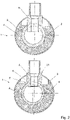
- Fig. 1 shows a sectional view through a pre-insulated pipeline 1 with a cylindrical branch pipe, which is known from the prior art.
- the aim is to show the effect of the eccentricity of the connected branch pipe with a cylindrical end or a conical end according to the invention.
- Both variants show the branch pipe with the same offset to the center of medium pipe 2.
- the end of the branch pipe protrudes further into the medium pipe and thus creates unwanted resistance.
- the branch pipe Since it is imperative for good stability that the entire lateral surface of the bore surrounds the end of the branch pipe, the branch pipe must be placed so deep, otherwise it would not be guaranteed that the branch pipe on the left side is sufficiently supported by the bore circumference and that there is too little material for a good weld would be present.
- the bore 7 is smaller and therefore does not have to protrude so far down into the medium pipe 2 to be supported by the entire circumference of the bore or so that there is enough material for welding .
- the cone 8 has a cone angle ⁇ between 10 and 45°.
Abstract
Verfahren und System zum Anbringen eines Abzweigrohres (5) an einer vorisolierten Rohrleitung (1) enthaltend ein Mediumrohr (2), eine Isolationsschicht (4) und ein Mantelrohr (3), beinhaltend folgende Schritte:
• Freilegen eines bestimmten Bereichs des Mediumrohres durch Heraustrennen und Entfernen eines zylindrischen Bereichs (6) der Isolationsschicht der Rohrleitung, wobei die Mittelachse des herauszutrennenden zylindrischen Bereichs rechtwinklig zur Rohrleitungsachse der vorisolierten Rohrleitung verläuft,
• Durchbohren der Wandung des Mediumrohres (2) im freigelegtem Bereich,
• Erwärmen des entstandenen Bohrungsumfangs (7) im Mediumrohr mittels Heizwerkzeug (15),
• Erwärmen des Abzweigrohres (5) mittels Heizwerkzeug (15),
• Einpressen des erwärmten Abzweigrohres in die erwärmte Bohrung,
wobei das Erwärmen des Bohrungsumfangs und das Erwärmen des Abzweigrohres gleichzeitig erfolgt.

• Exposing a specific area of the carrier pipe by cutting out and removing a cylindrical area (6) of the insulation layer of the pipeline, with the central axis of the cylindrical area to be cut out running at right angles to the axis of the pre-insulated pipeline,
• Drilling through the wall of the medium pipe (2) in the exposed area,
• Heat up the circumference of the hole (7) in the medium pipe using a heating tool (15),
• heating the branch pipe (5) using a heating tool (15),
• Pressing the heated branch pipe into the heated bore,
wherein the heating of the bore circumference and the heating of the branch pipe are carried out simultaneously.
Description
Die Erfindung betrifft ein Verfahren und ein System zum Anbringen eines Abzweigrohres vorzugsweise für einen Sensoranschluss an einer vorisolierten Rohrleitung, enthaltend ein Mediumrohr, eine Isolationsschicht und ein Mantelrohr, beinhaltend folgende Schritte:
- Freilegen eines bestimmten Bereichs des Mediumrohres durch Heraustrennen und Entfernen eines zylindrischen Bereichs der Isolationsschicht der Rohrleitung, wobei die Mittelachse des herauszutrennenden zylindrischen Bereichs rechtwinklig zur Rohrleitungsachse der vorisolierten Rohrleitung verläuft,
- Durchbohren der Wandung des Mediumrohres im freigelegtem Bereich,
- Erwärmen des entstandenen Bohrungsumfangs im Mediumrohr mittels Heizwerkzeug,
- Erwärmen des Abzweigrohres mittels Heizwerkzeug,
- Einpressen des erwärmten Abzweigrohres in die erwärmte Bohrung.
- Exposing a certain area of the carrier pipe by cutting out and removing a cylindrical area of the insulation layer of the pipeline, with the central axis of the cylindrical area to be cut out running at right angles to the axis of the pre-insulated pipeline,
- Drilling through the wall of the carrier pipe in the exposed area,
- Heating the circumference of the hole in the medium pipe using a heating tool,
- heating the branch pipe using a heating tool,
- Pressing the heated branch pipe into the heated bore.
Abzweigrohre sind aus dem Stand der Technik bekannt und werden meist für den Anschluss an nicht isolierte Rohrleitungen mittels eines Anbohrsattelstücks oder Anbohr-T-Stücks umgesetzt.Branch pipes are known from the state of the art and are usually implemented for connection to non-insulated pipelines by means of a tapping saddle piece or tapping T-piece.
Bei vorisolierten Rohrleitungen wird in der Regel ein bereits vorfabriziertes und vorisoliertes T-Stück in die Rohrleitung eingebaut, was ein nachträgliches Anbringen eines Abzweigrohres erübrigt. In der Regel sind solche T-Stücke mit demselben oder leicht reduzierten Stutzen als Abgang ausgebildet gegenüber den Anschlüssen an die Hauptleitung und somit meist überdimensioniert für den Anschluss von Sensoren. Zudem muss das vor oder während der Installation eingeplant werden oder wenn dies nachträglich erfolgen soll, muss dazu ein Stück aus der verlegten vorisolierten Rohrleitung entfernt werden und ein solches T-Stück eingesetzt werden.In the case of pre-insulated pipelines, a prefabricated and pre-insulated T-piece is usually installed in the pipeline, which makes it unnecessary to subsequently attach a branch pipe. As a rule, such T-pieces are designed with the same or slightly reduced socket as the outlet opposite the connections to the main line and are therefore usually oversized for the connection of sensors. In addition, this must be planned before or during installation, or if this is to be done later, a piece of the pre-insulated pipeline must be removed and such a T-piece inserted.
Aus der
Im oben aufgeführten Stand der Technik ist es mehr oder weniger erforderlich, bei bereits vorisolierten Rohrleitungen mit einem Mediumrohr aus Kunststoff ein standard T-Stück einzuplanen und einzubauen, das für Sensorzugänge meist überdimensioniert ist. Oder als Alternative aus den bekannten Systemen, die Verwendung eines metallischen Mediumrohrs und das anzuschliessende Abzweigrohr ebenfalls aus einem metallischen Werkstoff, wobei hier der Nachteil des metallischen Werkstoffs ist und dies in manchen Bereichen aufgrund der Anwendung nicht zulässig ist und auch ein höheres Gewicht und Korrosionsprobleme mit sich bringt.In the state of the art mentioned above, it is more or less necessary to plan and install a standard T-piece for already pre-insulated pipelines with a medium pipe made of plastic, which is usually oversized for sensor access. Or as an alternative from the known systems, the use of a metal medium pipe and the branch pipe to be connected, also made of a metal material, whereby the disadvantage here is the metal material and this is not permissible in some areas due to the application and also a higher weight and corrosion problems brings.
Es ist Aufgabe der Erfindung ein System und ein damit verbundenes Verfahren vorzuschlagen, das ermöglicht an bereits verlegten, vorisolierte Rohrleitungen mit einem Mediumrohr aus Kunststoff ein Abzweigrohr oder ein Formstück mit rohrförmigen Anschlussbereich aus Kunststoff anzuschliessen, wobei der Anschluss eine genügend hohe Stabilität aufweisen muss. Zudem soll das durchfliessende Medium im Mediumrohr möglichst nicht durch das Abzweigrohr behindert werden wie auch das Anschliessen eines Abzweigrohres einfach durchzuführen sein soll aber dennoch gewährleistet ist, dass die Befestigung den Anforderungen entspricht und neben einer hohen Masshaltigkeit auch eine Reproduzierbarkeit gewährleistet.It is the object of the invention to propose a system and a method associated with it that enables a branch pipe or a fitting with a tubular connection area made of plastic to be connected to already laid, pre-insulated pipelines with a medium pipe made of plastic, with the connection having to have a sufficiently high level of stability. In addition, the medium flowing through the medium pipe should not be impeded by the branch pipe, and it should also be easy to connect a branch pipe, but it should still be ensured that the attachment meets the requirements and, in addition to high dimensional accuracy, also ensures reproducibility.
Diese Aufgabe wird erfindungsgemäss dadurch gelöst, dass das Erwärmen des Bohrungsumfangs und das Erwärmen des Abzweigrohres gleichzeitig erfolgt. Zudem ist das Abzweigrohr am mit der Rohrleitung zu verschweissenden Ende konisch ausgebildet und durch Erwärmung mittels Schweisstool am Mediumrohr angeschweisst.According to the invention, this object is achieved in that the heating of the bore circumference and the heating of the branch pipe take place simultaneously. In addition, the branch pipe has a conical shape at the end to be welded to the pipeline and is welded to the medium pipe by heating with a welding tool.
Das erfindungsgemässe Verfahren zum Anbringen eines Abzweigrohres an einer vorisolierten Rohrleitung, enthaltend ein Mediumrohr aus Kunststoff, eine Isolationsschicht und ein Mantelrohr, beinhaltet die folgenden Schritte. Um das Abzweigrohr am Mediumrohr anschliessen zu können wird das Mediumrohr freigelegt. Dies erfolgt durch ein Heraustrennen des Mantelrohres und der Isolationsschicht, wobei dazu ein zylindrischer Bereich der Isolationsschicht und des darüber angeordneten Mantelrohres abgetrennt und entfernt wird. Die Mittelachse des herauszutrennenden zylindrischen Bereichs verläuft senkrecht bzw. im rechten Winkel zur Mittelachse der vorisolierten Rohrleitung. Um die Rechtwinkligkeit zur Rohrleitung sicherzustellen, kann vorzugsweise mit einer auf die Rohrleitung aufgesetzten Führung gearbeitet werden, die das Trennwerkzeug beim Heraustrennen bzw. Abtrennen des zylindrischen Bereichs führt. Das Heraustrennen bzw. Abtrennen erfolgt vorzugsweise mittels eines Trennwerkzeugs, beispielsweise einer Lochsäge, wodurch eine zylindrische Form aus der Isolationsschicht und dem Mantelrohr abgetrennt wird und mittels eines weiteren Werkzeugs, wie beispielsweise eines Schraubenziehers, kann die Isolationsschicht herausgebrochen werden. Durch das vorhergehende Trennen des zylindrischen Bereichs liegt eine saubere Kontur vor. Anschliessend wird im freigelegten Bereich die Wandung des Mediumrohres durchbohrt. Für das Durchbohren kann mit einem Bohrwerkzeug gearbeitet werden, welches an die Geometrie des zylindrischen Bereichs angepasst ist, damit eine exakte Führung gewährleisten werden kann. Das heisst, vorzugsweise weist das Bohrwerkzeuge einen Bereich auf, der dem Durchmesser des zylindrischen Bereichs entspricht, wodurch das Bohrwerkzeug axial geführt ist. Der entstandene Bohrumfang wird mittels eines Heizwerkzeugs erwärmt, wobei die Form des Heizwerkzeugs vorzugsweise konisch ausgebildet ist. Das anzuschliessende Abzweigrohr wird ebenso mittels eines Heizwerkzeugs erwärmt. Daraufhin wird das Abzweigrohr mit dem erwärmten Ende in die erwärmte Bohrung gepresst und für einige Sekunden so gehalten bis sich die Schweissnaht, die sich gebildet hat etwas verfestigt. Erfindungsgemäss erfolgt das Erwärmen des Umfangs der Bohrung im Mediumrohr und das Erwärmen des Abzweigrohres gleichzeitig.The method according to the invention for attaching a branch pipe to a pre-insulated pipeline, containing a service pipe made of plastic, an insulation layer and a jacket pipe, includes the following steps. In order to be able to connect the branch pipe to the medium pipe, the medium pipe is exposed. This is done by cutting out the jacket tube and the Insulation layer, for which purpose a cylindrical area of the insulation layer and the jacket tube arranged above it is separated and removed. The central axis of the cylindrical area to be cut out is perpendicular or at right angles to the central axis of the pre-insulated pipeline. In order to ensure perpendicularity to the pipeline, one can preferably work with a guide placed on the pipeline, which guides the separating tool when the cylindrical area is separated or cut off. The cutting out or severing is preferably carried out using a severing tool, for example a hole saw, whereby a cylindrical shape is separated from the insulation layer and the casing tube and the insulation layer can be broken out using another tool, such as a screwdriver. A clean contour is obtained by previously separating the cylindrical area. The wall of the carrier pipe is then drilled through in the exposed area. A drilling tool can be used for drilling through, which is adapted to the geometry of the cylindrical area so that exact guidance can be guaranteed. This means that the drilling tool preferably has an area which corresponds to the diameter of the cylindrical area, as a result of which the drilling tool is guided axially. The resulting bore circumference is heated by means of a heating tool, the shape of the heating tool preferably being conical. The branch pipe to be connected is also heated using a heating tool. The branch pipe is then pressed with the heated end into the heated bore and held for a few seconds until the weld seam that has formed hardens a little. According to the invention, the heating of the circumference of the bore in the carrier pipe and the heating of the branch pipe take place simultaneously.
Es ist vorteilhaft, wenn das Erwärmen des Umfanges der Bohrung im Mediumrohr und das Ende des Abzweigrohres mit demselben Heizwerkzeug erfolgt. Vorzugsweise weist das Heizwerkzeug dazu zwei Heizkulissen auf, die gleichzeitig erwärmt werden und an denen jeweils der Bohrungsumfang und das Abzweigrohr erwärmt werden.It is advantageous if the circumference of the bore in the medium pipe and the end of the branch pipe are heated with the same heating tool. For this purpose, the heating tool preferably has two heating elements, which are heated simultaneously and on which the circumference of the bore and the branch pipe are heated.
Es ist vorteilhaft, wenn das Freilegen mittels eines Trennwerkzeugs erfolgt, wobei das Trennwerkzeug zentrisch geführt wird. Dazu wird vorzugsweise ein zentraler Führungsbohrer zur Zentrierung des Trennwerkzeugs verwendet und gleichzeitig eine Führungsbohrung durch den Rohrleitungsquerschnitt gebildet.It is advantageous if the exposure takes place by means of a separating tool, with the separating tool being guided centrally. This is preferably a central Pilot drill used to center the cutting tool while also forming a pilot hole through the cross-section of the pipe.
Es ist vorteilhaft wenn das Durchbohren der Wandung des Mediumrohres zweifach geführt wird, wobei dies mittels der Führungsbohrung und dem Durchmesser des zylindrischen Bereichs erzielt wird. Das Bohrwerkzeug weist vorzugsweise einen zentralen Führungsbohrer auf sowie im oberen Bereich einen Durchmesser, der mit dem Durchmesser des zylindrischen Bereichs fluchtet, wodurch der Bohrvorgang zweifach geführt ist und dadurch eine senkrechte und gerade Ausrichtung zur Mittelachse gewährleistet.It is advantageous if the wall of the medium pipe is drilled through twice, this being achieved by means of the guide bore and the diameter of the cylindrical area. The drilling tool preferably has a central guide drill and, in the upper area, a diameter which is aligned with the diameter of the cylindrical area, as a result of which the drilling process is carried out twice and thus ensures vertical and straight alignment with the central axis.
Als bevorzugte Ausführungsform ist auch der Fügevorgang mit Hilfe des Durchmessers des zylindrischen Bereichs geführt. Dazu fluchtet der Aussendurchmesser der Halterung mit Durchmesser des zylindrischen Bereichs.As a preferred embodiment, the joining process is also performed using the diameter of the cylindrical area. For this purpose, the outer diameter of the bracket is aligned with the diameter of the cylindrical area.
Vorzugsweise erfolgt das Einpressen des Abzweigrohres bis an einen vorgegebenen Anschlag, wobei der Anschlag an der Halterung oder am Abzweigrohr angeordnet ist.The branch pipe is preferably pressed in up to a predetermined stop, the stop being arranged on the holder or on the branch pipe.
Als vorteilhaft hat sich auch gezeigt, wenn die Tiefe des herauszutrennenden zylindrischen Bereichs der Isolationsschicht über einen Anschlag am Trennwerkzeug festgelegt wird. Dadurch ist gewährleistet, dass nicht zu tief in das Rohr hineingeschnitten wird um zu vermeiden, dass das Mediumrohr verletzt wird, aber dennoch sichergestellt wird, dass die Isolationsschicht in diesem zylindrischen Bereich bis hin zur Aussenmantelfläche des Mediumrohres entfernt werden kann.It has also been shown to be advantageous if the depth of the cylindrical region of the insulation layer to be cut out is determined by a stop on the cutting tool. This ensures that the pipe is not cut too deeply in order to avoid damaging the carrier pipe, but still ensures that the insulation layer can be removed in this cylindrical area up to the outer surface of the carrier pipe.
Gemäss einer bevorzugten Ausführungsform wird das Durchbohren der Wandung des Mediumrohres bis zu einem festgelegten Anschlag durchgeführt. Dadurch wird sichergestellt, dass nicht aus Versehen in die gegenüberliegende Wandung hineingebohrt wird und das Mediumrohr an der Innenmantelfläche verletzt wird.According to a preferred embodiment, the wall of the carrier pipe is pierced up to a fixed stop. This ensures that the opposite wall is not accidentally drilled into and the medium pipe is damaged on the inner surface.
Die vorliegende Erfindung offenbart ein System eines Abzweigrohres für einen Sensoranschluss an einer verlegten, vorisolierten Rohrleitung bestehend aus einem Mediumrohr aus Kunststoff, einem Mantelrohr und einer dazwischen angeordneten Isolationsschicht. An der Rohrleitung liegt ein freigelegter zylindrischer Bereich vor, wo die Isolationsschicht und das Mantelrohr entfernt wurden. Der zylindrische Bereich bzw. dessen Mittelachse ist rechtwinklig auf die Mittelachse der Rohrleitung ausgerichtet. Durch die Wandung des Mediumrohres verläuft eine Bohrung konzentrisch zum zylindrischen Bereich. Zudem weist das System ein in der Bohrung angeordnetes Abzweigrohr auf. Das Abzweigrohr ist am zu verschweissenden Ende konisch ausgebildet und mit dem Mediumrohr verschweisst, wobei die Schweissung durch die Erwärmung des Abzweigrohres und die Erwärmung des Umfangs der Bohrung im Mediumrohr mittels Heizwerkzeug durchgeführt wird. Durch die konische Form am Ende des Abzweigrohres ist gewährleistet, dass das Abzweigrohr nur soweit durch die Bohrung ragt, dass der Umfang der Bohrung bzw. dessen Mantelfläche komplett am Abzweigrohr anliegt auch wenn die Bohrung nicht mit der Mittelachse des Mediumrohres fluchtet bzw. nicht zentrisch auf das Mediumrohr ausgerichtet ist. Ein solcher Versatz kann entstehen, wenn das Mantelrohr nicht konzentrisch mit dem Mediumrohr verläuft. Dies kann durchaus der Fall sein bei vorisolierten Rohren. Aufgrund dessen, dass das Abzweigrohr zentrisch auf das Mantelrohr gerichtet ist, was aufgrund des Verfahrens zum Anschliessen des Abzweigrohrs und dem Anbringen des zylindrischen Bereichs erfolgt, kann es sein, dass die Mittelachse der Bohrung versetzt zum Zentrum des Mediumrohres verläuft. Würde hier nun ein zylindrisches Ende eines Abzweigrohres eingebracht werden, müsste das weit in das Mediumrohr hineinragen um sicher zu stellen, dass die komplette Mantelfläche des Bohrumfangs am Abzweigrohr anliegt, da bei einem Versatz auf der einen Seite der Bohrung die Bohrungsmantelfläche tiefer hinunter ragt. Mittels eines Konus als Ende des Abzweigrohres, welcher von der Bohrung aufgenommen wird, ist auch bei einem exzentrischen Versatz gewährleistet, dass das Abzweigrohr nicht tief in das Mediumrohr hineinragt. Aufgrund des Konus weist das Abzweigrohr am Ende einen kleineren Durchmesser auf was eine kleinere Bohrung bedarf. Dennoch bildet die Mantelfläche der Bohrung durch die schräge Kontaktfläche mit dem Konus eine genügend grosse Auflagefläche um die benötigte Stabilität der Verschweissung zu erreichen.The present invention discloses a system of a branch pipe for a sensor connection to a laid, pre-insulated pipeline, consisting of a medium pipe made of plastic, a casing pipe and one arranged in between insulation layer. There is an exposed cylindrical area on the pipeline where the insulation layer and casing pipe have been removed. The cylindrical area or its central axis is aligned at right angles to the central axis of the pipeline. A hole runs through the wall of the carrier pipe concentrically to the cylindrical area. In addition, the system has a branch pipe arranged in the bore. The branch pipe has a conical shape at the end to be welded and is welded to the medium pipe, with the welding being carried out by heating the branch pipe and heating the circumference of the bore in the medium pipe using a heating tool. The conical shape at the end of the branch pipe ensures that the branch pipe only protrudes through the bore to such an extent that the circumference of the bore or its lateral surface is in full contact with the branch pipe, even if the bore is not aligned with the central axis of the medium pipe or is not centered the medium pipe is aligned. Such an offset can occur if the casing pipe is not concentric with the carrier pipe. This may well be the case with pre-insulated pipes. Due to the fact that the branch pipe is centered on the casing pipe, which occurs due to the method of connecting the branch pipe and attaching the cylindrical portion, it is possible that the central axis of the bore is offset from the center of the service pipe. If a cylindrical end of a branch pipe were to be introduced here, it would have to protrude far into the medium pipe to ensure that the entire outer surface of the bore circumference rests against the branch pipe, since the outer surface of the bore protrudes deeper if there is an offset on one side of the bore. Using a cone as the end of the branch pipe, which is received by the bore, ensures that the branch pipe does not protrude deep into the medium pipe, even with an eccentric offset. Due to the cone, the branch pipe has a smaller diameter at the end, which requires a smaller bore. Nevertheless, due to the inclined contact surface with the cone, the lateral surface of the bore forms a sufficiently large contact surface to achieve the required stability of the weld.
Vorzugsweise weist der Konus am Ende des Abzweigrohres einen Winkel zwischen 10 bis 45° auf, vorzugsweise 18 bis 35°.The cone at the end of the branch pipe preferably has an angle of between 10 and 45°, preferably 18 and 35°.
Vorzugsweise weist das Abzweigrohr einen Anschlag zur Begrenzung des Fügewegs auf, wobei der Anschlag durch eine am Aussendurchmesser des Abzweigrohres angeordnete Schulter gebildet ist oder durch das Ende des Abzweigrohres indem der Anschlag in der Halterung während des Fügens axial begrenzt ist.The branch pipe preferably has a stop for limiting the joining path, the stop being formed by a shoulder arranged on the outside diameter of the branch pipe or by the end of the branch pipe in which the stop is axially limited in the holder during joining.
Alle Ausgestaltungmöglichkeiten sind untereinander frei kombinierbar, sowie Verfahrensmerkmale mit Systemmerkmalen und umgekehrt miteinander kombinierbar sind.All design options can be freely combined with one another, and method features can be combined with system features and vice versa.
Ein Ausführungsbeispiel der Erfindung wird anhand der Figuren beschrieben, wobei sich die Erfindung nicht nur auf das Ausführungsbeispiel beschränkt. Es zeigen:
- Fig. 1
- den Ablauf des erfindungsgemässen Verfahrens und
- Fig. 2
- einen Schnitt durch ein zylindrisches Abzweigrohr und ein erfindungsgemässes konisches Abzweigrohr.
- 1
- the course of the method according to the invention and
- 2
- a section through a cylindrical branch pipe and an inventive conical branch pipe.
Die in
Hingegen bei der erfindungsgemässen Lösung mit einem Konus 8 am Ende des Abzweigrohres 5 fällt die Bohrung 7 kleiner aus und muss dadurch auch nicht so weit nach unten in das Medimrohr 2 ragen um vom kompletten Bohrungsumfang gestützt zu werden bzw. damit genügend Material für eine Schweissung vorliegt. Der Konus 8 weist einen Konuswinkel α zwischen 10 und 45° auf.In contrast, in the solution according to the invention with a
- 11
- Rohrleitungpipeline
- 22
- Mediumrohrmedium pipe
- 33
- Mantelrohrcasing pipe
- 44
- Isolationsschichtinsulation layer
- 55
- Abzweigrohrbranch pipe
- 66
- zylindrischer Bereichcylindrical area
- 77
- Bohrungdrilling
- 88th
- Konus AbzweigrohrCone branch pipe
- 99
- zylindrischer Abzweigrohr Stand der Technikprior art cylindrical branch pipe
- 1010
- Trennwerkzeugparting tool
- 1111
- Tiefenanschlag TrennwerkzeugDepth stop cutting tool
- 1212
- Schraubenzieherscrewdriver
- 1313
- Bohrwerkzeugdrilling tool
- 1414
- Anschlag Bohrwerkzeugstop drilling tool
- 1515
- Heizwerkzeugheating tool
- 1616
- Konus-HeizkulisseCone heating backdrop
- 1717
- Innenkonus-HeizkulisseInner cone heating backdrop
- 1818
- Halterungbracket
- 1919
- Anschlag Halterungstop bracket
- 2020
- zylindrische Abtrennungcylindrical partition
- 2121
- Anschlag am Abzweigrohrstop on the branch pipe
- 2222
- Führungsbohrungpilot hole
- 2323
- Führungsbohrerpilot drill
Claims (11)
Priority Applications (1)
| Application Number | Priority Date | Filing Date | Title |
|---|---|---|---|
| EP20212814.6A EP4012240A1 (en) | 2020-12-09 | 2020-12-09 | Branch tube for sensor connection |
Applications Claiming Priority (1)
| Application Number | Priority Date | Filing Date | Title |
|---|---|---|---|
| EP20212814.6A EP4012240A1 (en) | 2020-12-09 | 2020-12-09 | Branch tube for sensor connection |
Publications (1)
| Publication Number | Publication Date |
|---|---|
| EP4012240A1 true EP4012240A1 (en) | 2022-06-15 |
Family
ID=73789970
Family Applications (1)
| Application Number | Title | Priority Date | Filing Date |
|---|---|---|---|
| EP20212814.6A Pending EP4012240A1 (en) | 2020-12-09 | 2020-12-09 | Branch tube for sensor connection |
Country Status (1)
| Country | Link |
|---|---|
| EP (1) | EP4012240A1 (en) |
Citations (6)
| Publication number | Priority date | Publication date | Assignee | Title |
|---|---|---|---|---|
| JPH01196546A (en) * | 1988-02-01 | 1989-08-08 | Fuji Tekomu Kk | Internal inspection of piping and apparatus therefor |
| EP1314539A1 (en) * | 2001-11-27 | 2003-05-28 | RITMO s.r.l. | Device for thermal welding of connectors on the wall of plastic pipes |
| WO2011034417A1 (en) * | 2009-09-15 | 2011-03-24 | Thermaflex International Holding B.V. | Conduit assembly |
| DE102013015038A1 (en) * | 2013-09-12 | 2015-03-12 | Endress + Hauser Flowtec Ag | Measuring tube for a flowmeter and flowmeter |
| EP2957812A2 (en) | 2014-06-16 | 2015-12-23 | Pipeteq Systems A/S | A process for producing a branch on a pre-insulated pipe |
| EP3656991A1 (en) * | 2018-11-23 | 2020-05-27 | Eberspächer Exhaust Technology GmbH | Method for manufacturing of an exhaust system |
-
2020
- 2020-12-09 EP EP20212814.6A patent/EP4012240A1/en active Pending
Patent Citations (6)
| Publication number | Priority date | Publication date | Assignee | Title |
|---|---|---|---|---|
| JPH01196546A (en) * | 1988-02-01 | 1989-08-08 | Fuji Tekomu Kk | Internal inspection of piping and apparatus therefor |
| EP1314539A1 (en) * | 2001-11-27 | 2003-05-28 | RITMO s.r.l. | Device for thermal welding of connectors on the wall of plastic pipes |
| WO2011034417A1 (en) * | 2009-09-15 | 2011-03-24 | Thermaflex International Holding B.V. | Conduit assembly |
| DE102013015038A1 (en) * | 2013-09-12 | 2015-03-12 | Endress + Hauser Flowtec Ag | Measuring tube for a flowmeter and flowmeter |
| EP2957812A2 (en) | 2014-06-16 | 2015-12-23 | Pipeteq Systems A/S | A process for producing a branch on a pre-insulated pipe |
| EP3656991A1 (en) * | 2018-11-23 | 2020-05-27 | Eberspächer Exhaust Technology GmbH | Method for manufacturing of an exhaust system |
Similar Documents
| Publication | Publication Date | Title |
|---|---|---|
| DE69900161T3 (en) | ELECTRIC WELDING CLUTCH | |
| EP0170844B1 (en) | Shaped piercing piece consisting of weldable plastics | |
| DE2437880A1 (en) | METHOD OF WELDING PIPES | |
| EP0272511A2 (en) | Method of making pipe joints for high pressure hydraulic pipelines | |
| EP2020272A1 (en) | Method and device for welding circular seams | |
| EP0519223A1 (en) | Gastight coupling between pipes of small diameter and method and apparatus for manufacture | |
| DE102007002606A1 (en) | eothermal probe foot for inserting into a borehole comprises an electric welding sleeve for producing a connection to a service pipe | |
| EP0096175B1 (en) | Weldless joint | |
| EP4012240A1 (en) | Branch tube for sensor connection | |
| DE102018107017A1 (en) | Socket with sensor connection and method for attaching a sensor to a pipeline | |
| DE1627483A1 (en) | Process for joining clad pipes by welding without deposit metal | |
| DE102016221144B3 (en) | Method for connecting at least two components | |
| DE3715184A1 (en) | CONNECTING ARRANGEMENT | |
| DE19509586C1 (en) | Union piece for metal pipe | |
| EP3298316B1 (en) | Flange connection for components composed of plastic, in particular for tubular components composed of plastic | |
| EP1927806A1 (en) | Device for connecting two pipes | |
| EP0204145A1 (en) | Insert for coupling pipes by welding | |
| DD259662A1 (en) | BRACKETS ON STEEL TUBES | |
| EP3730826B1 (en) | Method for producing a pipe with connecting flange | |
| DE4136349A1 (en) | Appts. for welding plastic tubes together - prevents formation of internal weld beads, and has metal heating ring and plate holding, e.g. PTFE, ring fitting into one tube | |
| DE2612661C2 (en) | Branch for welding pipes to a collector | |
| EP0445902A1 (en) | Thermal insulated conduit | |
| EP4015887A1 (en) | Connecting element for a pipe arrangement and arrangement | |
| DE4332269C2 (en) | Connection set for radiators and method for producing a connection set | |
| EP1048885B1 (en) | Apparatus for manufacturing a connection of a tap with a conduit |
Legal Events
| Date | Code | Title | Description |
|---|---|---|---|
| PUAI | Public reference made under article 153(3) epc to a published international application that has entered the european phase |
Free format text: ORIGINAL CODE: 0009012 |
|
| STAA | Information on the status of an ep patent application or granted ep patent |
Free format text: STATUS: THE APPLICATION HAS BEEN PUBLISHED |
|
| AK | Designated contracting states |
Kind code of ref document: A1 Designated state(s): AL AT BE BG CH CY CZ DE DK EE ES FI FR GB GR HR HU IE IS IT LI LT LU LV MC MK MT NL NO PL PT RO RS SE SI SK SM TR |
|
| STAA | Information on the status of an ep patent application or granted ep patent |
Free format text: STATUS: REQUEST FOR EXAMINATION WAS MADE |
|
| 17P | Request for examination filed |
Effective date: 20221130 |
|
| RBV | Designated contracting states (corrected) |
Designated state(s): AL AT BE BG CH CY CZ DE DK EE ES FI FR GB GR HR HU IE IS IT LI LT LU LV MC MK MT NL NO PL PT RO RS SE SI SK SM TR |
|
| P01 | Opt-out of the competence of the unified patent court (upc) registered |
Effective date: 20230529 |
|
| STAA | Information on the status of an ep patent application or granted ep patent |
Free format text: STATUS: EXAMINATION IS IN PROGRESS |
|
| 17Q | First examination report despatched |
Effective date: 20240104 |