EP4012198B1 - Sperranordnung - Google Patents
Sperranordnung Download PDFInfo
- Publication number
- EP4012198B1 EP4012198B1 EP21205757.4A EP21205757A EP4012198B1 EP 4012198 B1 EP4012198 B1 EP 4012198B1 EP 21205757 A EP21205757 A EP 21205757A EP 4012198 B1 EP4012198 B1 EP 4012198B1
- Authority
- EP
- European Patent Office
- Prior art keywords
- fastening sheet
- hinge
- fastener
- sliding rail
- hinge shaft
- Prior art date
- Legal status (The legal status is an assumption and is not a legal conclusion. Google has not performed a legal analysis and makes no representation as to the accuracy of the status listed.)
- Active
Links
Images


Classifications
-
- F—MECHANICAL ENGINEERING; LIGHTING; HEATING; WEAPONS; BLASTING
- F16—ENGINEERING ELEMENTS AND UNITS; GENERAL MEASURES FOR PRODUCING AND MAINTAINING EFFECTIVE FUNCTIONING OF MACHINES OR INSTALLATIONS; THERMAL INSULATION IN GENERAL
- F16B—DEVICES FOR FASTENING OR SECURING CONSTRUCTIONAL ELEMENTS OR MACHINE PARTS TOGETHER, e.g. NAILS, BOLTS, CIRCLIPS, CLAMPS, CLIPS OR WEDGES; JOINTS OR JOINTING
- F16B13/00—Dowels or other devices fastened in walls or the like by inserting them in holes made therein for that purpose
- F16B13/04—Dowels or other devices fastened in walls or the like by inserting them in holes made therein for that purpose with parts gripping in the hole or behind the reverse side of the wall after inserting from the front
- F16B13/08—Dowels or other devices fastened in walls or the like by inserting them in holes made therein for that purpose with parts gripping in the hole or behind the reverse side of the wall after inserting from the front with separate or non-separate gripping parts moved into their final position in relation to the body of the device without further manual operation
- F16B13/0808—Dowels or other devices fastened in walls or the like by inserting them in holes made therein for that purpose with parts gripping in the hole or behind the reverse side of the wall after inserting from the front with separate or non-separate gripping parts moved into their final position in relation to the body of the device without further manual operation by a toggle-mechanism
-
- F—MECHANICAL ENGINEERING; LIGHTING; HEATING; WEAPONS; BLASTING
- F16—ENGINEERING ELEMENTS AND UNITS; GENERAL MEASURES FOR PRODUCING AND MAINTAINING EFFECTIVE FUNCTIONING OF MACHINES OR INSTALLATIONS; THERMAL INSULATION IN GENERAL
- F16B—DEVICES FOR FASTENING OR SECURING CONSTRUCTIONAL ELEMENTS OR MACHINE PARTS TOGETHER, e.g. NAILS, BOLTS, CIRCLIPS, CLAMPS, CLIPS OR WEDGES; JOINTS OR JOINTING
- F16B2/00—Friction-grip releasable fastenings
- F16B2/02—Clamps, i.e. with gripping action effected by positive means other than the inherent resistance to deformation of the material of the fastening
- F16B2/06—Clamps, i.e. with gripping action effected by positive means other than the inherent resistance to deformation of the material of the fastening external, i.e. with contracting action
- F16B2/065—Clamps, i.e. with gripping action effected by positive means other than the inherent resistance to deformation of the material of the fastening external, i.e. with contracting action using screw-thread elements
-
- A—HUMAN NECESSITIES
- A47—FURNITURE; DOMESTIC ARTICLES OR APPLIANCES; COFFEE MILLS; SPICE MILLS; SUCTION CLEANERS IN GENERAL
- A47K—SANITARY EQUIPMENT NOT OTHERWISE PROVIDED FOR; TOILET ACCESSORIES
- A47K13/00—Seats or covers for all kinds of closets
- A47K13/24—Parts or details not covered in, or of interest apart from, groups A47K13/02 - A47K13/22, e.g. devices imparting a swinging or vibrating motion to the seats
- A47K13/26—Mounting devices for seats or covers
Definitions
- the present invention relates to the technical field of fixing devices, and in particular to a locking assembly.
- expansion bolts are combinations of expansion bolts and screw rods.
- the expansion bolt made of plastic or rubber is installed into a reserved hole of the toilet body; then the screw rod penetrates an installation support to be connected to the expansion bolt, to fix the installation support of the cover plate; and finally, a rotary shaft of the cover plate is connected to the installation support, to rotatably install the cover plate.
- the expansion bolt made of plastic or rubber
- the screw rod penetrates an installation support to be connected to the expansion bolt, to fix the installation support of the cover plate
- a rotary shaft of the cover plate is connected to the installation support, to rotatably install the cover plate.
- most expansion bolts will creep and loosen after long-term use, and are likely to be damaged when violently installed.
- EP1512874 , CN209966254U and CN106725061A disclose a locking assembly, comprising:
- the present invention aims to solve one of the technical problems in the art described above at least to a certain extent.
- a locking assembly comprising:
- the retainer may be provided with a first sliding rail and a second sliding rail which are oppositely arranged and in communication with each other, a first end of the hinge shaft moving in the first sliding rail , a second end of the hinge shaft moving in the second sliding rail , and the first end and the second end of the hinge shaft being provided with opposite sliding planes separately.
- At least one of opposite side walls of one ends, close to a first inclined guide surface and a second inclined guide surface , of the first sliding rail and the second sliding rail may be provided with a limiting protrusion point , the limiting protrusion point dividing the first sliding rail and the second sliding rail into upper travel sections and lower travel sections, and the lower travel sections exactly accommodating the hinge shaft .
- a locking assembly including a retainer and a fastener, the retainer being provided with a sliding groove, and the fastener being capable of moving in the sliding groove, having a relative disengagement state and a relative engagement state, being capable of being accommodated in the retainer when in the relative engagement state, and being provided with a limiting structure for keeping the fastener at a specific disengagement angle.
- the fastener is used as a locking abutment, to realize a locking function when in the relative disengagement state; and the fastener may be accommodated in the retainer when in the relative engagement state, to reduce an entire width of the fastener, and thus it is convenient to disassemble the retainer and the fastener integrally, and the locking assembly is rapidly disassembled and reusable.
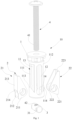
- Fig. 1 is an exploded perspective view of a locking assembly
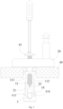
- Fig. 2 is an assembled perspective view of the locking assembly with an angle opposite that in Fig. 1 .
- a locking assembly 10 in accordance with the present invention includes a retainer 1 and a fastener 2, the retainer 1 being provided with a sliding groove 11, the fastener 2 being formed by hinging two fastening sheets 21, 22 through a hinge shaft 3, the two fastening sheets being capable of moving in the sliding grooves 11, having a relative disengagement state and a relative engagement state, and being capable of being accommodated in the retainer 1 when in the relative engagement state, and a limiting structure for keeping the two fastening sheets at a specific disengagement angle being arranged between the two fastening sheets.
- the fastener 2 may be formed by hinging a first fastening sheet 21 and a second fastening sheet 22 through the hinge shaft 3, and the hinge shaft 3 may be a cylindrical nut.
- the two fastening sheets are used as locking abutments, to realize a locking function when in the relative disengagement state; and the two fastening sheets may be accommodated in the retainer 1 when in the relative engagement state, to reduce an entire width of the two fastening sheets, and thus it is convenient to disassemble the retainer 1 and the fastener 2 integrally, and the locking assembly is rapidly disassembled and reusable.
- the first fastening sheet 21 and the second fastening sheet 22 include first hinge plates 211, 221 and second hinge plates 212, 222 which are oppositely arranged, and connecting plates 213, 223 for connecting the first hinge plates 211, 221 and the second hinge plates 212, 222, that is, the first fastening sheet 21 and the second fastening sheet 22 have the same structure, and the first fastening sheet 21 and the second fastening sheet 22 are oppositely arranged, the hinge shaft 3 being connected to the first hinge plates 211, 221 and the second hinge plates 212, 222.
- Parts, close to hinge ends, of the connecting plates 213, 223 of the first fastening sheet 21 and the second fastening sheet 22 are provided with cut grooves 214, 224 separately.
- the limiting structure which keeps the first fastening sheet 21 and the second fastening sheet 22 at the specific disengagement angle enables an end part of the hinge end of the first hinge plate 211 of the first fastening sheet 21 to be in abutting fit with a bottom of the cut groove 224 of the second fastening sheet 22, and an end part of the hinge end of the first hinge plate 221 of the second fastening sheet 22 to be in abutting fit with a bottom of the cut groove 214 of the first fastening sheet 21.
- first hinge plates 211, 221 and the second hinge plates 212, 222 of the first fastening sheet 21 and the second fastening sheet 22 are triangular, and installation holes for the hinge shaft 3 are provided in the first hinge plates 211, 221 and the second hinge plates 212, 222.
- the sliding grooves 11 include a first sliding groove 111 and a second sliding groove 112 which are oppositely arranged and in communication with each other, the first fastening sheet 21 moving in the first sliding groove 111, and the second fastening sheet 22 moving in the second sliding groove 112. In this way, the fastener 2 moves stably.
- the first sliding groove 111 is provided with a first inclined guide surface 113 for engaging the first fastening sheet 21 relative to the second fastening sheet 22, and the second sliding groove 112 is provided with a second inclined guide surface 114 for engaging the second fastening sheet 22 relative to the first fastening sheet 21, the first inclined guide surface 113 being opposite the second inclined guide surface 114.
- the retainer 1 is generally installed in a vertical direction.
- the first inclined guide surface 113 and the second inclined guide surface 114 are arranged on bottom side walls of the first sliding groove 111 and the second sliding groove 112 correspondingly.
- the retainer 1 is provided with a first sliding rail 12 and a second sliding rail 13 which are oppositely arranged and in communication with each other, a first end of the hinge shaft 3 moving in the first sliding rail 12, and a second end of the hinge shaft 3 moving in the second sliding rail 13.
- the first end and the second end of the hinge shaft 3 are provided with opposite sliding planes 31 separately, that is, the first end of the hinge shaft 3 is provided with the opposite sliding plane 31, the opposite sliding plane 31 being preferably arranged in parallel, and similarly, the second end of the hinge shaft 3 is provided with the opposite sliding plane 31, the opposite sliding plane 31 being preferably arranged in parallel. In this way, it may be ensured that the hinge shaft 3 moves along the first sliding rail 12 and the second sliding rail 13 without deviation.
- At least one of opposite side walls of one ends, close to the first inclined guide surface 113 and the second inclined guide surface 114, of the first sliding rail 12 and the second sliding rail 13 is provided with a limiting protrusion point 14, the limiting protrusion point 14 dividing the first sliding rail 12 and the second sliding rail 13 into upper travel sections and lower travel sections, and the lower travel sections exactly accommodating the hinge shaft 3.
- both opposite side walls of the first sliding rail 12 are provided with limiting protrusion points 14, and both opposite side walls of the second sliding rail 13 are provided with limiting protrusion points 14, the limiting protrusion points 14 arranged on the opposite side walls of the first sliding rail 12 and the limiting protrusion points 14 arranged on the opposite side walls of the second sliding rail 13 having the same height.
- the locking assembly further includes an actuating positioner 4, the actuating positioner 4 being connected to the fastener 2 and capable of driving the fastener 2 to move and keeping the fastener 2 at a specific position.
- the actuating positioner 4 drives the fastener 2 to move to different positions
- the two fastening sheets have the relative disengagement state and the relative engagement state at different positions, and may be accommodated in the retainer 1 when in the relative engagement state
- the limiting structure for keeping the two fastening sheets at the specific disengagement angle is arranged between the two fastening sheets, and the limiting structure keeps the two fastening sheets in the relative disengagement state.
- the actuating positioner 4 includes a bolt 41 and a threaded through hole 42 radially formed in the hinge shaft 3, the bolt 41 penetrating the retainer 1 to be connected to the threaded through hole 42.
- the bolt 41 is rotated to drive the hinge shaft 3 to move, and the hinge shaft 3 and the fastener 2 move in the sliding groove 11.
- the hinge shaft 3 stops moving, and the hinge shaft 3 is positioned at a specific position, so that the locking assembly has a simple structure and a low cost.
- the bolt 41 penetrates a support 20 and the retainer 1 to be in threaded connection with the threaded through hole 42 provided on the hinge shaft 3, and the first fastening sheet 21 is engaged relative to the second fastening sheet 22 and placed in the retainer 1.
- the hinge shaft 3 is limited in the lower travel sections of the first sliding rail 12 and the second sliding rail 13 and is limited by the limiting protrusion point 14, and thus the first fastening sheet 21, the second fastening sheet 22, and the hinge shaft 3 will not fall off and are integrally formed into a retainer 1 assembly, which is inserted into an installation hole of a toilet body 40.
- the bolt 41 is screwed, to drive the hinge shaft 3, the first fastening sheet 21, and the second fastening sheet 22 to move
- the hinge shaft 3 moves upwards along the first sliding rail 12 and the second sliding rail 13 after passing over the limiting protrusion point 14, and the first end and the second end of the hinge shaft 3 are provided with the opposite sliding planes 31 separately, so as to ensure that the hinge shaft 3 may move up and down along the first sliding rail 12 and the second sliding rail 13 of the retainer 1 without deviating or falling off.
- the first fastening sheet 21 and the second fastening sheet 22 are disengaged to two sides under the action of gravity.
- the hinge shaft 3 rises continuously, disengagement angles of the first fastening sheet 21 and the second fastening sheet 22 are gradually increased, and the first fastening sheet 21 and the second fastening sheet 22 are clamped to each other through the limiting structure and kept at a specific disengagement angle.
- the first fastening sheet 21 and the second fastening sheet 22 are disengaged by a maximum angle and cannot be disengaged any more, the bolt 41 is screwed continuously, the first fastening sheet 21 and the second fastening sheet 22 abut against a lower surface of the toilet body 40, and the locking assembly 10 completely locks.
- the bolt 41 is unscrewed, to drive the hinge shaft 3, the first fastening sheet 21, and the second fastening sheet 22 to descend until the first fastening sheet 21 and the second fastening sheet 22 make contact with the first inclined guide surface 113 and the second inclined guide surface 114 of the retainer 1 respectively, and the first fastening sheet 21 and the second fastening sheet 22 are engaged inward to be closed.
- the hinge shaft 3 passes over the limiting protrusion point 14 and the bolt 41 is pressed downwards, a prompt sound showing that the hinge shaft 3 retreats to an exact position is obviously sensed.
- the first fastening sheet 21 and the second fastening sheet 22 may be completely retracted into the retainer 1, to realize unlocking.
- the locking assembly 10 may be taken out integrally and reusable, and thus is rapidly disassembled and reusable.
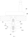
- Fig. 7 is a structural schematic diagram of the locking assembly 10, installed at a toilet.
- a toilet includes a locking assembly 10, a support 20, and a cover plate 30.
- the support 20 is installed on a toilet body 40 by means of the locking assembly 10, and the cover plate 30 is installed on the support 20.
- the locking assembly 10 includes a retainer 1 and a fastener 2, the retainer 1 being provided with a sliding groove 11, the fastener 2 being formed by hinging two fastening sheets, the two fastening sheets being capable of moving in the sliding grooves 11, having a relative disengagement state and a relative engagement state, and being capable of being accommodated in the retainer 1 when in the relative engagement state, and a limiting structure for keeping the two fastening sheets at a specific disengagement angle being arranged between the two fastening sheets.
- the support 20 is installed on the toilet body 40 by means of the locking assembly 10, and the cover plate 30 is installed on the support 20.
- the two fastening sheets of the locking assembly are used as locking abutments, to realize a locking function when in the relative disengagement state; the two fastening sheets may be accommodated in the retainer 1 when in the relative engagement state, to reduce an entire width of the two fastening sheets, and thus it is convenient to disassemble the retainer 1 and the fastener 2 integrally, and the locking assembly is rapidly disassembled and reusable.
- central In the description of the present invention, it is to be understood that the terms “central”, “longitudinal”, “transverse”, “length”, “width”, “thickness”, “up”, “down”, “front”, “back”, “left”, “right”, “vertical”, “horizontal”, “top”, “bottom”, “inner”, “outer”, “clockwise”, “counterclockwise”, etc. indicate azimuthal or positional relations based on those shown in the accompanying drawings only for ease of description of the present invention and for simplicity of description, and are not intended to indicate or imply that the referenced device or element must have a particular orientation and be constructed and operative in a particular orientation, and thus may not be construed as a limitation on the present invention.
- first and second are for descriptive purposes only and are not to be construed as indicating or implying the relative importance or implicitly specifying the number of indicated technical features.
- a feature defined with “first” and “second” may explicitly or implicitly include one or more of the feature.
- “plurality” means two or more, unless expressly specified otherwise.
- the terms "install”, “connect”, “connected”, “fix”, etc. are to be construed broadly and, for example, may be fixedly connected, or detachably connected, or integrally formed; may be mechanically connected, or electrically connected; and may be direct connected or indirect connected via an intermediary medium, or may be an internal communication between two elements or an interworking relation between two elements.
- install may be fixedly connected, or detachably connected, or integrally formed; may be mechanically connected, or electrically connected; and may be direct connected or indirect connected via an intermediary medium, or may be an internal communication between two elements or an interworking relation between two elements.
- a case that a first feature is "above” or “below” a second feature may be direct contact between the first and second features, or contact between the first and second features through another feature therebetween, not direct contact. Also, a case that the first feature is "above”, “on the upper portion of", and “on” the second feature may be that the first feature is right above and diagonally above the second feature, or simply indicates that a horizontal height of the first feature is higher than that of the second feature.
- a case that the first feature is "below”, “on the lower portion of”, and “underneath” the second feature may be that the first feature is right below and diagonally below the second feature, or simply indicates that a horizontal height of the first feature is lower than that of the second feature.
Landscapes
- Engineering & Computer Science (AREA)
- General Engineering & Computer Science (AREA)
- Mechanical Engineering (AREA)
- Health & Medical Sciences (AREA)
- Public Health (AREA)
- Toilet Supplies (AREA)
Claims (3)
- Verriegelungsanordnung (10), umfassend:einen Halter (1), der mit einer ersten und einer zweiten Gleitrille (111, 112) bereitgestellt ist, die einander gegenüberliegend angeordnet sind und miteinander in Verbindung stehen, wobei sich das erste Befestigungsteil in der ersten Gleitrille bewegt und sich das zweite Befestigungsteil in der zweiten Gleitrille bewegt;eine Scharnierwelle (3), die in der Lage ist, sich in der ersten und in der zweiten Gleitrille (111, 112) zu bewegen; undein Befestigungselement (2), das ein erstes und ein zweites Befestigungsteil (21, 22) aufweist, die getrennt voneinander an der Scharnierwelle (3) eingehängt sind, wobei das Befestigungselement (2) einen relativen Freigabezustand und einen relativen Eingriffszustand aufweist, wobei jedes Befestigungselement (2) in der Lage ist, in dem Halter (1) aufgenommen zu werden, wenn es sich in dem relativen Freigabezustand befindet, und mit einer Begrenzungsstruktur bereitgestellt ist, um das Befestigungselement (2) in einem bestimmten Freigabewinkel zu halten, wobei die Verriegelungsanordnung ferner einen Betätigungspositionierer umfasst, wobei der Betätigungspositionierer mit dem Befestigungselement verbunden ist und in der Lage ist, das Befestigungselement anzutreiben, um sich zu bewegen, und das Befestigungselement in einer bestimmten Position zu halten, wobei der Betätigungspositionierer einen Bolzen und ein Gewindedurchgangsloch, das radial in der Scharnierwelle ausgebildet ist, umfasst, wobei der Bolzen den Halter durchdringt, um mit dem Gewindedurchgangsloch verbunden zu werden, dadurch gekennzeichnet, dass das erste Befestigungsteil und das zweite Befestigungsteil erste Scharnierplatten und zweite Scharnierplatten, die einander gegenüberliegend angeordnet sind, und Verbindungsplatten zum Verbinden der ersten Scharnierplatte mit der zweiten Scharnierplatte umfassen, wobei Teile der Verbindungsplatten des ersten Befestigungsteils und des zweiten Befestigungsteils in der Nähe der Scharnierenden getrennt voneinander mit geschnittenen Rillen versehen sind; und die Begrenzungsstruktur es ermöglicht, dass ein Endteil des Scharnierendes der ersten Scharnierplatte des ersten Befestigungsteils an einem Boden der geschnittenen Rille des zweiten Befestigungsteils anliegt und dass ein Endteil des Scharnierendes der ersten Scharnierplatte des zweiten Befestigungsteils an einem Boden der geschnittenen Rille des ersten Befestigungsteils anliegt, wobei die erste Gleitrille (111) mit einer ersten geneigten Führungsfläche (113) bereitgestellt ist, um das erste Befestigungsteil (21) relativ zu dem zweiten Befestigungsteil (22) in Eingriff zu bringen, wobei die zweite Gleitrille (112) mit einer zweiten geneigten Führungsfläche (114) bereitgestellt ist, um das zweite Befestigungsteil (22) relativ zu dem ersten Befestigungsteil (21) in Eingriff zu bringen, wobei die erste geneigte Führungsfläche (113) gegenüber der zweiten geneigten Führungsfläche (114) angeordnet ist.
- Verriegelungsanordnung (10) nach Anspruch 1, wobei der Halter (1) mit einer ersten Gleitschiene (12) und einer zweiten Gleitschiene (13) bereitgestellt ist, die einander gegenüberliegend angeordnet sind und miteinander in Verbindung stehen, ein erstes Ende der Scharnierwelle (3) sich in der ersten Gleitschiene (12) bewegt, ein zweites Ende der Scharnierwelle (3) sich in der zweiten Gleitschiene (13) bewegt und das erste Ende und das zweite Ende der Scharnierwelle (3) getrennt voneinander mit entgegengesetzten Gleitebenen bereitgestellt sind.
- Verriegelungsanordnung (10) nach Anspruch 2, wobei mindestens eine von gegenüberliegenden Seitenwänden eines Endes der ersten Gleitschiene (12) und der zweiten Gleitschiene (13) in der Nähe einer ersten geneigten Führungsfläche (113) und einer zweiten geneigten Führungsfläche (114) mit einem begrenzenden Vorsprungspunkt (14) bereitgestellt ist, wobei der begrenzende Vorsprungspunkt (14) die erste Gleitschiene (12) und die zweite Gleitschiene (13) in obere Bewegungsabschnitte und untere Bewegungsabschnitte unterteilt und wobei die unteren Bewegungsabschnitte die Scharnierwelle (3) exakt aufnehmen.
Applications Claiming Priority (1)
| Application Number | Priority Date | Filing Date | Title |
|---|---|---|---|
| CN202011422695 | 2020-12-08 |
Publications (2)
| Publication Number | Publication Date |
|---|---|
| EP4012198A1 EP4012198A1 (de) | 2022-06-15 |
| EP4012198B1 true EP4012198B1 (de) | 2025-04-23 |
Family
ID=78483203
Family Applications (1)
| Application Number | Title | Priority Date | Filing Date |
|---|---|---|---|
| EP21205757.4A Active EP4012198B1 (de) | 2020-12-08 | 2021-11-01 | Sperranordnung |
Country Status (2)
| Country | Link |
|---|---|
| US (1) | US20220178393A1 (de) |
| EP (1) | EP4012198B1 (de) |
Families Citing this family (1)
| Publication number | Priority date | Publication date | Assignee | Title |
|---|---|---|---|---|
| CN216044797U (zh) * | 2021-08-11 | 2022-03-15 | 中山市美图塑料工业有限公司 | 一种紧固组件 |
Family Cites Families (10)
| Publication number | Priority date | Publication date | Assignee | Title |
|---|---|---|---|---|
| US3302508A (en) * | 1966-03-15 | 1967-02-07 | Louis Rolnick | Toggle bolt |
| US6884012B2 (en) * | 2003-09-04 | 2005-04-26 | Illinois Tool Works Inc. | Heavy duty toggle bolt fastener assembly, and method of installing and removing the same |
| US7226261B1 (en) * | 2005-12-08 | 2007-06-05 | Bristol Steven L | Toggle assembly |
| US9757164B2 (en) * | 2013-01-07 | 2017-09-12 | Spinal Simplicity Llc | Interspinous process implant having deployable anchor blades |
| US9861399B2 (en) * | 2009-03-13 | 2018-01-09 | Spinal Simplicity, Llc | Interspinous process implant having a body with a removable end portion |
| DE102011100235A1 (de) * | 2011-05-02 | 2012-11-08 | Trw Automotive Gmbh | Befestigungsclip zum Montieren eines Bauteils |
| US9188142B2 (en) * | 2011-08-18 | 2015-11-17 | Empire Technology Development | Hinged arm mechanically activated fastener |
| US9919657B2 (en) * | 2015-09-04 | 2018-03-20 | Arctic Cat, Inc. | Retaining device for vehicle racks |
| CN106725061B (zh) * | 2017-03-02 | 2022-05-27 | 泉州科牧智能厨卫有限公司 | 一种马桶盖板固定装置 |
| CN209966254U (zh) * | 2019-03-12 | 2020-01-21 | 海益(厦门)建材工业有限公司 | 一种螺栓锁紧结构 |
-
2021
- 2021-11-01 EP EP21205757.4A patent/EP4012198B1/de active Active
- 2021-12-07 US US17/543,750 patent/US20220178393A1/en not_active Abandoned
Also Published As
| Publication number | Publication date |
|---|---|
| EP4012198A1 (de) | 2022-06-15 |
| US20220178393A1 (en) | 2022-06-09 |
Similar Documents
| Publication | Publication Date | Title |
|---|---|---|
| EP3080375B1 (de) | Vorrichtung für das verschliessen einer gebäudeöffnung | |
| US9234374B2 (en) | Integrated lock and latch device for sliding windows | |
| US20230046879A1 (en) | Outdoor structure design and components | |
| EP4012198B1 (de) | Sperranordnung | |
| EP2432673B1 (de) | Heizeinrichtung für schienenfahrzeuge | |
| JP2021536208A (ja) | ソーラーパネル用の調節金具および支持システム | |
| US20150034420A1 (en) | Scaffold Deck System With Bracket-Supported Partial Length Planks For Creating An Opening To Accommodate Obstacles | |
| WO2007122072A2 (de) | Mehrteiliges haushaltsgerät | |
| CN215861138U (zh) | 一种锁附组件 | |
| SE500606C2 (sv) | Dörr för ställverkskåp | |
| US8827348B2 (en) | Self locking and unlocking hinge | |
| EP3245345A1 (de) | Pfosten-riegel-konstruktion | |
| EP3034744B1 (de) | Schiebewandsystem | |
| CN210342935U (zh) | 一种五金安装结构 | |
| WO2009092141A1 (en) | Improvements in structures including wings | |
| EP1253032A2 (de) | Elektrische Heizeinrichtung mit in einem Rahmen gehaltenen Heizblock | |
| CN223503889U (zh) | 一种存储柜 | |
| CN220285520U (zh) | 一种新型铰链式对开门重力锁 | |
| CN221565761U (zh) | 一种用于隧道巡检轨道对接的升降台 | |
| CN112277735B (zh) | 导电轨的绝缘支撑装置以及导电轨组件 | |
| CN222121958U (zh) | 连接锁及显示单元 | |
| EP4108848B1 (de) | Terrassenbodenunterkonstruktion mit einem untertragrahmen für bodenbeläge | |
| CN221478193U (zh) | 一种钢边箱锁扣结构 | |
| CN223151963U (zh) | 一种关节结构及具有其的门栏 | |
| EP2372063B1 (de) | Umkehrbare Fensteranordnung |
Legal Events
| Date | Code | Title | Description |
|---|---|---|---|
| PUAI | Public reference made under article 153(3) epc to a published international application that has entered the european phase |
Free format text: ORIGINAL CODE: 0009012 |
|
| STAA | Information on the status of an ep patent application or granted ep patent |
Free format text: STATUS: REQUEST FOR EXAMINATION WAS MADE |
|
| 17P | Request for examination filed |
Effective date: 20211122 |
|
| AK | Designated contracting states |
Kind code of ref document: A1 Designated state(s): AL AT BE BG CH CY CZ DE DK EE ES FI FR GB GR HR HU IE IS IT LI LT LU LV MC MK MT NL NO PL PT RO RS SE SI SK SM TR |
|
| STAA | Information on the status of an ep patent application or granted ep patent |
Free format text: STATUS: EXAMINATION IS IN PROGRESS |
|
| 17Q | First examination report despatched |
Effective date: 20240319 |
|
| GRAP | Despatch of communication of intention to grant a patent |
Free format text: ORIGINAL CODE: EPIDOSNIGR1 |
|
| STAA | Information on the status of an ep patent application or granted ep patent |
Free format text: STATUS: GRANT OF PATENT IS INTENDED |
|
| INTG | Intention to grant announced |
Effective date: 20250124 |
|
| GRAS | Grant fee paid |
Free format text: ORIGINAL CODE: EPIDOSNIGR3 |
|
| GRAA | (expected) grant |
Free format text: ORIGINAL CODE: 0009210 |
|
| STAA | Information on the status of an ep patent application or granted ep patent |
Free format text: STATUS: THE PATENT HAS BEEN GRANTED |
|
| AK | Designated contracting states |
Kind code of ref document: B1 Designated state(s): AL AT BE BG CH CY CZ DE DK EE ES FI FR GB GR HR HU IE IS IT LI LT LU LV MC MK MT NL NO PL PT RO RS SE SI SK SM TR |
|
| REG | Reference to a national code |
Ref country code: GB Ref legal event code: FG4D |
|
| REG | Reference to a national code |
Ref country code: CH Ref legal event code: EP |
|
| REG | Reference to a national code |
Ref country code: DE Ref legal event code: R096 Ref document number: 602021029525 Country of ref document: DE |
|
| REG | Reference to a national code |
Ref country code: IE Ref legal event code: FG4D |
|
| REG | Reference to a national code |
Ref country code: NL Ref legal event code: MP Effective date: 20250423 |
|
| PG25 | Lapsed in a contracting state [announced via postgrant information from national office to epo] |
Ref country code: NL Free format text: LAPSE BECAUSE OF FAILURE TO SUBMIT A TRANSLATION OF THE DESCRIPTION OR TO PAY THE FEE WITHIN THE PRESCRIBED TIME-LIMIT Effective date: 20250423 |
|
| REG | Reference to a national code |
Ref country code: AT Ref legal event code: MK05 Ref document number: 1787997 Country of ref document: AT Kind code of ref document: T Effective date: 20250423 |
|
| PG25 | Lapsed in a contracting state [announced via postgrant information from national office to epo] |
Ref country code: ES Free format text: LAPSE BECAUSE OF FAILURE TO SUBMIT A TRANSLATION OF THE DESCRIPTION OR TO PAY THE FEE WITHIN THE PRESCRIBED TIME-LIMIT Effective date: 20250423 Ref country code: FI Free format text: LAPSE BECAUSE OF FAILURE TO SUBMIT A TRANSLATION OF THE DESCRIPTION OR TO PAY THE FEE WITHIN THE PRESCRIBED TIME-LIMIT Effective date: 20250423 Ref country code: PT Free format text: LAPSE BECAUSE OF FAILURE TO SUBMIT A TRANSLATION OF THE DESCRIPTION OR TO PAY THE FEE WITHIN THE PRESCRIBED TIME-LIMIT Effective date: 20250825 |
|
| REG | Reference to a national code |
Ref country code: LT Ref legal event code: MG9D |
|
| PG25 | Lapsed in a contracting state [announced via postgrant information from national office to epo] |
Ref country code: NO Free format text: LAPSE BECAUSE OF FAILURE TO SUBMIT A TRANSLATION OF THE DESCRIPTION OR TO PAY THE FEE WITHIN THE PRESCRIBED TIME-LIMIT Effective date: 20250723 Ref country code: GR Free format text: LAPSE BECAUSE OF FAILURE TO SUBMIT A TRANSLATION OF THE DESCRIPTION OR TO PAY THE FEE WITHIN THE PRESCRIBED TIME-LIMIT Effective date: 20250724 |
|
| PG25 | Lapsed in a contracting state [announced via postgrant information from national office to epo] |
Ref country code: PL Free format text: LAPSE BECAUSE OF FAILURE TO SUBMIT A TRANSLATION OF THE DESCRIPTION OR TO PAY THE FEE WITHIN THE PRESCRIBED TIME-LIMIT Effective date: 20250423 |
|
| PG25 | Lapsed in a contracting state [announced via postgrant information from national office to epo] |
Ref country code: BG Free format text: LAPSE BECAUSE OF FAILURE TO SUBMIT A TRANSLATION OF THE DESCRIPTION OR TO PAY THE FEE WITHIN THE PRESCRIBED TIME-LIMIT Effective date: 20250423 |
|
| PG25 | Lapsed in a contracting state [announced via postgrant information from national office to epo] |
Ref country code: HR Free format text: LAPSE BECAUSE OF FAILURE TO SUBMIT A TRANSLATION OF THE DESCRIPTION OR TO PAY THE FEE WITHIN THE PRESCRIBED TIME-LIMIT Effective date: 20250423 |
|
| PG25 | Lapsed in a contracting state [announced via postgrant information from national office to epo] |
Ref country code: AT Free format text: LAPSE BECAUSE OF FAILURE TO SUBMIT A TRANSLATION OF THE DESCRIPTION OR TO PAY THE FEE WITHIN THE PRESCRIBED TIME-LIMIT Effective date: 20250423 |
|
| PG25 | Lapsed in a contracting state [announced via postgrant information from national office to epo] |
Ref country code: RS Free format text: LAPSE BECAUSE OF FAILURE TO SUBMIT A TRANSLATION OF THE DESCRIPTION OR TO PAY THE FEE WITHIN THE PRESCRIBED TIME-LIMIT Effective date: 20250723 |
|
| PG25 | Lapsed in a contracting state [announced via postgrant information from national office to epo] |
Ref country code: IS Free format text: LAPSE BECAUSE OF FAILURE TO SUBMIT A TRANSLATION OF THE DESCRIPTION OR TO PAY THE FEE WITHIN THE PRESCRIBED TIME-LIMIT Effective date: 20250823 |
|
| PG25 | Lapsed in a contracting state [announced via postgrant information from national office to epo] |
Ref country code: LV Free format text: LAPSE BECAUSE OF FAILURE TO SUBMIT A TRANSLATION OF THE DESCRIPTION OR TO PAY THE FEE WITHIN THE PRESCRIBED TIME-LIMIT Effective date: 20250423 |