EP4011515A1 - Verfahren und vorrichtung zum koaxialen strangpressen eines strangpressprodukts - Google Patents
Verfahren und vorrichtung zum koaxialen strangpressen eines strangpressprodukts Download PDFInfo
- Publication number
- EP4011515A1 EP4011515A1 EP20213457.3A EP20213457A EP4011515A1 EP 4011515 A1 EP4011515 A1 EP 4011515A1 EP 20213457 A EP20213457 A EP 20213457A EP 4011515 A1 EP4011515 A1 EP 4011515A1
- Authority
- EP
- European Patent Office
- Prior art keywords
- bore
- ram
- pickup
- receiver
- extrusion
- Prior art date
- Legal status (The legal status is an assumption and is not a legal conclusion. Google has not performed a legal analysis and makes no representation as to the accuracy of the status listed.)
- Granted
Links
Images

Classifications
-
- B—PERFORMING OPERATIONS; TRANSPORTING
- B21—MECHANICAL METAL-WORKING WITHOUT ESSENTIALLY REMOVING MATERIAL; PUNCHING METAL
- B21C—MANUFACTURE OF METAL SHEETS, WIRE, RODS, TUBES, PROFILES OR LIKE SEMI-MANUFACTURED PRODUCTS OTHERWISE THAN BY ROLLING; AUXILIARY OPERATIONS USED IN CONNECTION WITH METAL-WORKING WITHOUT ESSENTIALLY REMOVING MATERIAL
- B21C31/00—Control devices for metal extruding, e.g. for regulating the pressing speed or temperature of metal; Measuring devices, e.g. for temperature of metal, combined with or specially adapted for use in connection with extrusion presses
-
- B—PERFORMING OPERATIONS; TRANSPORTING
- B29—WORKING OF PLASTICS; WORKING OF SUBSTANCES IN A PLASTIC STATE IN GENERAL
- B29C—SHAPING OR JOINING OF PLASTICS; SHAPING OF MATERIAL IN A PLASTIC STATE, NOT OTHERWISE PROVIDED FOR; AFTER-TREATMENT OF THE SHAPED PRODUCTS, e.g. REPAIRING
- B29C48/00—Extrusion moulding, i.e. expressing the moulding material through a die or nozzle which imparts the desired form; Apparatus therefor
- B29C48/16—Articles comprising two or more components, e.g. co-extruded layers
- B29C48/18—Articles comprising two or more components, e.g. co-extruded layers the components being layers
- B29C48/21—Articles comprising two or more components, e.g. co-extruded layers the components being layers the layers being joined at their surfaces
-
- B—PERFORMING OPERATIONS; TRANSPORTING
- B21—MECHANICAL METAL-WORKING WITHOUT ESSENTIALLY REMOVING MATERIAL; PUNCHING METAL
- B21C—MANUFACTURE OF METAL SHEETS, WIRE, RODS, TUBES, PROFILES OR LIKE SEMI-MANUFACTURED PRODUCTS OTHERWISE THAN BY ROLLING; AUXILIARY OPERATIONS USED IN CONNECTION WITH METAL-WORKING WITHOUT ESSENTIALLY REMOVING MATERIAL
- B21C23/00—Extruding metal; Impact extrusion
- B21C23/02—Making uncoated products
- B21C23/04—Making uncoated products by direct extrusion
- B21C23/14—Making other products
- B21C23/142—Making profiles
-
- B—PERFORMING OPERATIONS; TRANSPORTING
- B21—MECHANICAL METAL-WORKING WITHOUT ESSENTIALLY REMOVING MATERIAL; PUNCHING METAL
- B21C—MANUFACTURE OF METAL SHEETS, WIRE, RODS, TUBES, PROFILES OR LIKE SEMI-MANUFACTURED PRODUCTS OTHERWISE THAN BY ROLLING; AUXILIARY OPERATIONS USED IN CONNECTION WITH METAL-WORKING WITHOUT ESSENTIALLY REMOVING MATERIAL
- B21C23/00—Extruding metal; Impact extrusion
- B21C23/02—Making uncoated products
- B21C23/18—Making uncoated products by impact extrusion
- B21C23/183—Making uncoated products by impact extrusion by forward extrusion
-
- B—PERFORMING OPERATIONS; TRANSPORTING
- B21—MECHANICAL METAL-WORKING WITHOUT ESSENTIALLY REMOVING MATERIAL; PUNCHING METAL
- B21C—MANUFACTURE OF METAL SHEETS, WIRE, RODS, TUBES, PROFILES OR LIKE SEMI-MANUFACTURED PRODUCTS OTHERWISE THAN BY ROLLING; AUXILIARY OPERATIONS USED IN CONNECTION WITH METAL-WORKING WITHOUT ESSENTIALLY REMOVING MATERIAL
- B21C23/00—Extruding metal; Impact extrusion
- B21C23/22—Making metal-coated products; Making products from two or more metals
-
- B—PERFORMING OPERATIONS; TRANSPORTING
- B21—MECHANICAL METAL-WORKING WITHOUT ESSENTIALLY REMOVING MATERIAL; PUNCHING METAL
- B21C—MANUFACTURE OF METAL SHEETS, WIRE, RODS, TUBES, PROFILES OR LIKE SEMI-MANUFACTURED PRODUCTS OTHERWISE THAN BY ROLLING; AUXILIARY OPERATIONS USED IN CONNECTION WITH METAL-WORKING WITHOUT ESSENTIALLY REMOVING MATERIAL
- B21C27/00—Containers for metal to be extruded
-
- B—PERFORMING OPERATIONS; TRANSPORTING
- B21—MECHANICAL METAL-WORKING WITHOUT ESSENTIALLY REMOVING MATERIAL; PUNCHING METAL
- B21C—MANUFACTURE OF METAL SHEETS, WIRE, RODS, TUBES, PROFILES OR LIKE SEMI-MANUFACTURED PRODUCTS OTHERWISE THAN BY ROLLING; AUXILIARY OPERATIONS USED IN CONNECTION WITH METAL-WORKING WITHOUT ESSENTIALLY REMOVING MATERIAL
- B21C37/00—Manufacture of metal sheets, rods, wire, tubes, profiles or like semi-manufactured products, not otherwise provided for; Manufacture of tubes of special shape
- B21C37/04—Manufacture of metal sheets, rods, wire, tubes, profiles or like semi-manufactured products, not otherwise provided for; Manufacture of tubes of special shape of rods or wire
- B21C37/042—Manufacture of coated wire or rods
-
- B—PERFORMING OPERATIONS; TRANSPORTING
- B29—WORKING OF PLASTICS; WORKING OF SUBSTANCES IN A PLASTIC STATE IN GENERAL
- B29C—SHAPING OR JOINING OF PLASTICS; SHAPING OF MATERIAL IN A PLASTIC STATE, NOT OTHERWISE PROVIDED FOR; AFTER-TREATMENT OF THE SHAPED PRODUCTS, e.g. REPAIRING
- B29C48/00—Extrusion moulding, i.e. expressing the moulding material through a die or nozzle which imparts the desired form; Apparatus therefor
- B29C48/022—Extrusion moulding, i.e. expressing the moulding material through a die or nozzle which imparts the desired form; Apparatus therefor characterised by the choice of material
-
- B—PERFORMING OPERATIONS; TRANSPORTING
- B29—WORKING OF PLASTICS; WORKING OF SUBSTANCES IN A PLASTIC STATE IN GENERAL
- B29C—SHAPING OR JOINING OF PLASTICS; SHAPING OF MATERIAL IN A PLASTIC STATE, NOT OTHERWISE PROVIDED FOR; AFTER-TREATMENT OF THE SHAPED PRODUCTS, e.g. REPAIRING
- B29C48/00—Extrusion moulding, i.e. expressing the moulding material through a die or nozzle which imparts the desired form; Apparatus therefor
- B29C48/25—Component parts, details or accessories; Auxiliary operations
- B29C48/36—Means for plasticising or homogenising the moulding material or forcing it through the nozzle or die
- B29C48/475—Means for plasticising or homogenising the moulding material or forcing it through the nozzle or die using pistons, accumulators or press rams
- B29C48/48—Two or more rams or pistons
-
- B—PERFORMING OPERATIONS; TRANSPORTING
- B29—WORKING OF PLASTICS; WORKING OF SUBSTANCES IN A PLASTIC STATE IN GENERAL
- B29C—SHAPING OR JOINING OF PLASTICS; SHAPING OF MATERIAL IN A PLASTIC STATE, NOT OTHERWISE PROVIDED FOR; AFTER-TREATMENT OF THE SHAPED PRODUCTS, e.g. REPAIRING
- B29C48/00—Extrusion moulding, i.e. expressing the moulding material through a die or nozzle which imparts the desired form; Apparatus therefor
- B29C48/25—Component parts, details or accessories; Auxiliary operations
- B29C48/36—Means for plasticising or homogenising the moulding material or forcing it through the nozzle or die
- B29C48/49—Means for plasticising or homogenising the moulding material or forcing it through the nozzle or die using two or more extruders to feed one die or nozzle
-
- B—PERFORMING OPERATIONS; TRANSPORTING
- B30—PRESSES
- B30B—PRESSES IN GENERAL
- B30B11/00—Presses specially adapted for forming shaped articles from material in particulate or plastic state, e.g. briquetting presses, tabletting presses
- B30B11/22—Extrusion presses; Dies therefor
- B30B11/221—Extrusion presses; Dies therefor extrusion dies
-
- B—PERFORMING OPERATIONS; TRANSPORTING
- B30—PRESSES
- B30B—PRESSES IN GENERAL
- B30B11/00—Presses specially adapted for forming shaped articles from material in particulate or plastic state, e.g. briquetting presses, tabletting presses
- B30B11/22—Extrusion presses; Dies therefor
- B30B11/224—Extrusion chambers
-
- B—PERFORMING OPERATIONS; TRANSPORTING
- B30—PRESSES
- B30B—PRESSES IN GENERAL
- B30B11/00—Presses specially adapted for forming shaped articles from material in particulate or plastic state, e.g. briquetting presses, tabletting presses
- B30B11/22—Extrusion presses; Dies therefor
- B30B11/26—Extrusion presses; Dies therefor using press rams
-
- B—PERFORMING OPERATIONS; TRANSPORTING
- B30—PRESSES
- B30B—PRESSES IN GENERAL
- B30B15/00—Details of, or accessories for, presses; Auxiliary measures in connection with pressing
- B30B15/30—Feeding material to presses
- B30B15/302—Feeding material in particulate or plastic state to moulding presses
- B30B15/304—Feeding material in particulate or plastic state to moulding presses by using feed frames or shoes with relative movement with regard to the mould or moulds
- B30B15/306—Feeding material in particulate or plastic state to moulding presses by using feed frames or shoes with relative movement with regard to the mould or moulds for multi-layer articles
Definitions
- the invention relates to a method and a device for the coaxial extrusion of an extruded product.
- extrusion represents an energy-efficient way of producing semi-finished products, in particular near-net-shape, from primary material as an extruded product in just one forming step.
- Various materials can be processed.
- light metals such as aluminium, magnesium and titanium
- ferrous metals, non-ferrous metals and precious metals and their alloys can also be shaped.
- the process temperatures can be up to about 1300 °C, but can also be below 0 °C.
- the process makes it possible to adhere to the narrowest form tolerances and, in addition, to adapt the chemical and physical properties of the pressed products to the specific requirements of the end products via the microstructure.
- intermediate forged products and powder materials are also suitable as starting materials.
- the pure metal surfaces In order to bond metals together, the pure metal surfaces must come close to one another to within an atomic distance. In this case, both a sufficiently high pressure and a sufficiently high temperature must prevail in order to level the surface roughness and to generate the necessary approximation and to enable the diffusion processes necessary for chemical bonding. Since metal surfaces are generally covered with impurities and oxides, the "clean" surfaces must first be exposed in order to create a bond at the atomic level. In order for this to succeed, the contact surfaces of the two metal volumes must be sufficiently dimensions are increased. However, the cover layers must not increase in size or only to a very small extent in relation to the contact area.
- One way to tear open the surfaces of joining partners is to shear them together under the influence of normal stresses.
- the surface is thoroughly kneaded and thereby enlarged, which tears open the impurities and oxides so that the pure metal surface is exposed.
- the impurities and oxides can be greatly reduced on the one hand and the surface can be significantly enlarged on the other.
- extrusion offers the possibility of "pressing" separate material streams together during shaping and thereby creating a joint in the extruded product, the so-called extrusion seam or press seam.
- the temperatures and pressures required for this, as well as sufficient shearing, can be introduced using the extrusion process. In this way, different materials and alloys can be joined during extrusion.
- the extrusion of composites made of different metallic materials was examined in various works and the influence of the process variables on the composite properties was shown. Studies on the extrusion of material composites have also been carried out at the Extrusion Research Center in the past (cf.
- Negendank et al. J Mater Process Tech 212, 2012, 1954 ; Negendank et al., Key Engineering Materials 554-557, 2013, 767 ; Nitschke et al., Magnesium - 10th International Conference on Magnesium alloys and their applications (Editor: KU Kainer), 2015, 478 ). It could be shown that material composites can be produced with the help of different process variants of extrusion.
- Material composites can be produced using the hydrostatic extrusion process with the use of an active medium (cf. Ruppin et al., Aluminum 56, 1980, 523 ). In this way, direct contact and thus solid-body friction between the bolt, receiver and ram can be prevented or reduced (cf. Bauser et al., Extrusion, Aluminum-Verlag, Düsseldorf, 2001 ). For this reason, the process has an almost ideal material flow and enables the production of Cu/Al composites or Cu/Nb3Sn superconductors, for example.
- Multi-material cylindrical billets can be used in composite extrusion.
- magnesium hybrids can be formed and joined by extrusion.
- the pressing of alloy pairings with significant differences in the forming resistance leads to considerable difficulties in setting a homogeneous material flow, which leads to a pronounced distortion in the profile up to degradation of the profile in the area of the press seam.
- strong rotations and displacements of the interface relative to the profile cross-section can occur. These effects can depend on the respective volume fractions and the position of the pin parts (cf. Nitschke et al., Magnesium - 10th International Conference on Magnesium alloys and their applications (Editor: Kainer), 2015, 478 ).
- the object of the invention is to create a method and a device for the coaxial extrusion of an extruded product, with which extruded products can be produced more efficiently and variably.
- an extrusion molding apparatus including: a susceptor; a first pickup bore formed in the pickup and in which a first ram is disposed; a second pickup bore formed in the pickup within and coaxial with the first pickup bore and in which a second ram is disposed; and a molding tool with a mold cavity, which with the first and the second transducer bore are connected.
- the method also provides for the following: arranging a first bolt of material made of a first material in the first receiver bore; placing a second bolt of material of a second material in the second receiver bore; and extrusion of an extruded product, in which the first and the second material are positively and materially connected.
- the extrusion also includes the following: advancing the first press ram in the first receiver bore such that the first material is thereby pressed into the mold cavity of the mold and thereby deformed; advancing the second press ram in the second receiving bore in such a way that the second material is thereby pressed into the mold cavity of the mold and thereby deformed; and materially and positively connecting the first and the second material to form an extruded product in the mold.
- an apparatus for coaxially extruding an extrusion comprising: a susceptor; a first pickup bore formed in the pickup and in which a first ram is disposed; a second pickup bore formed in the pickup within and coaxial with the first pickup bore and in which a second ram is disposed; and a mold with a mold cavity which is connected to the first and the second receiver bore, such that during extrusion, by advancing the first ram in the first accommodator bore and advancing the second ram coaxially to the first ram in the second receiver bore, a first material of a first material bolt from the first receiver bore and a second material of a second material bolt from the second receiver bore for producing an extruded product, in which the first and the second material are positively and materially connected, can be introduced into the mold cavity.
- the movement of the press ram during advance takes place coaxially in the assigned receiver bores.
- the end of the receiver bores can couple directly to the mold cavity of the mold, so that the material exits the receiver bore directly into an entrance of the mold cavity.
- the receiving bores each form a compression channel, along which the material is subjected to pressure in order to bring it out of the receiving bore into the mold and thereby deform it.
- the pickup bores may be formed in a cylindrical shape.
- the materials are materially and positively connected in the mold along a joint connection (joint seam).
- the materials can be metallic materials of different types, for example aluminum or magnesium.
- the material and form-fitting connection can be carried out in the mold between the first and the second material.
- the shearing stress between the first and the second material in the mold cavity can be adjusted and varied by means of the mutually decoupled feed movement of the press dies in the separate receiver bores.
- the first and the second material can be introduced into the mold cavity at different relative speeds.
- the adjustability of different relative speeds enables the extrusion process to be adapted to different materials.
- the manufacturing process can also be optimized for the requirements of different extruded products.
- a first feed when the first press ram is advanced in the first receiver bore and a second feed when the second press ram is advanced in the second receiver bore can be regulated independently of one another.
- the decoupled adjustability or controllability of the feed of the press dies in the separate receiver bores allows an individual adjustment or steering of the extrusion process to different process managements, for example depending on the materials and / or the extruded product to be manufactured.
- the advancement of the first ram in the first receiver bore can be carried out at a first feed rate and the advancement of the second ram in the second receiver bore can be carried out at a second feed rate which is different from the first feed rate.
- the relative speeds for the materials during the transition from the receiver bore into the mold cavity of the mold can be adjusted by means of different feed speeds.
- the first ram can be driven by a first actuator when moving in the first receiving bore and the second ram can be driven by a second actuator when moving in the second receiving bore, which is formed and controllable separately from the first actuator.
- the rams are actuated with an actuator that is assigned to the rams in common.
- the common actuator can have decoupled actuator elements that can bring about a decoupled feed movement of the ram.
- a material which differs from the first material can be used as the second material.
- different metallic materials can be used.
- the same material can be used for the first and the second material.
- An extruded profile can be produced as an extruded product.
- the extruded profile can be manufactured with any profile cross-section.
- the process can be used to produce extruded profiles with axially variable volume proportions of different materials.
- extruded products with an axially variable cross-section and at the same time axially variable volume fractions of different materials can be produced.
- An extrusion device can be provided, in which the second receiver bore is arranged in an internal cavity of the first ram.
- the sensor bores can be formed with a round, angular or oval cross-section, in particular circular or different from circular.
- An extrusion device can be provided in which the second receiving bore is formed by the inner cavity of the first ram and the second ram is received in the inner cavity in a form-fitting manner.
- An extrusion device can be provided in which the second receiving bore is formed by means of a sleeve component which is arranged in the inner cavity of the first ram and the second ram is positively accommodated in the interior of the sleeve component.
- An extrusion molding device can be provided in which the first receiver bore and the second receiver bore are sealed from one another.
- the sensor bores can be sealed against one another in a fluid-tight manner, in particular in a liquid-tight manner.
- the receiver bores form a respective receptacle for the press ram (stamp receptacle).
- the individual material flows feed the mold cavity homogeneously, so that as little shearing as possible is generated in the pressing direction within the mold cavity and in the area of the pressing channel.
- This allows the contact shear stresses and also the axial expansion differences between the material partners to be minimized during the joining process.
- a homogeneous strand exit speed is achieved over the entire cross-section and damaging shearing in the area of the boundary layer is prevented.
- this means that streams of material with the same flow rate are brought together in the mold cavity and these can be pressed against one another with a minimum pressure in order to produce a material-bonding hybrid (extruded product).
- locally equally fast material flows can be realized with different pressing materials, which have different forming resistances and process windows.
- different pressing materials which have different forming resistances and process windows.
- the development of load-adapted, tailor-made profiles can reduce the weight of extruded components or assemblies compared to those produced via the conventional manufacturing process.
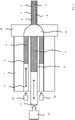
- the extruded product 1 shows a schematic representation of a device for producing an extruded product 1 by means of coaxial extrusion in section.
- a first material 2 and a second material 3 are connected to one another in a form-fitting and cohesive manner along a circumferential joint or seam 4 by means of extrusion are such that the second material 3 is surrounded axially circumferentially by the first material 2 .
- the extruded product 1 can be an extruded profile.
- extruded profile and “extruded product” in the meanings used here include all profile geometries that can be produced with the aid of the extrusion process. These include, for example, solid profiles as well as hollow profiles and semi-hollow profiles in any geometry.
- extruded “sheets” are known as extruded profiles, as are tubes, window profiles or round rods.
- a first material bolt 8 made of the first material 2 and a second material bolt 9 made of the second material 3 are arranged in a first and a second bore 5 , 6 of a pickup 7 .
- the first and the second pick-up bore 5, 6 provide a respective channel with a cylindrical shape, which can have a round, angular or oval cross-section.
- a first and a second press ram 10, 11 are arranged in the receiver bores 5, 6, which are each displaceable in the axial direction and here coaxially with one another in the associated receiver bore 5, 6.
- the first ram 10 is designed as a hollow component and surrounds the second receiver bore 6 when it is inserted into the first receiver bore.
- a wall 6a, which delimits the second sensor bore 6 and the inside of which faces the second sensor bore 6, can be designed as a separate wall between the first and the second sensor bore 5, 6.
- the second pickup bore 6 can be formed by means of a cavity in the first press die 10 .
- the second ram 11 can slide or slide in the cavity of the first ram 10 as it advances.
- the first and the second ram 10, 11 are assigned a first and a second actuator 12, 13, which are set up to apply force to the respective ram 10, 11, so that the ram 10, 11 performs a coaxial feed movement in the direction of a mold cavity 14 of a mold 15 so as to introduce the first and the second material 2, 3 into the mold cavity 14.
- the first and the second receiver bore 5, 6 are connected to the mold cavity 14 in such a way that the material of the first and the second material bolt 8, 9 is introduced into the mold cavity 14 and thereby deformed.
- the pressurization causes in the mold cavity 14 the joint 4 between the first and the second material 2, 3 is formed.
- the first actuator 12 is shown in two parts or pieces. However, it can be a single first actuator.
- the first and the second ram 10, 11 can perform feed movements that are decoupled from one another during extrusion.
- the first and the second ram 10, 11 can move at different speeds during the feed.
- the first and the second material 2, 3 which form an external and an internal material, can be different metallic materials, for example, but the use of the same metallic materials for the two material bolts 8, 9 can also be provided.
- the extruded product 1 produced can be an extruded profile.
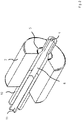
- FIG. 2 shows a schematic representation of an arrangement for an extrusion device for coaxial extrusion, in which the first and the second ram 10, 11 are arranged in the first and the second receiver bore 5, 6. While the first ram 10 is designed as a hollow ram, the second ram 11 is a solid material ram. In the first ram 10, the second receiving hole 6 for the second ram 11 is formed such that an outer surface of the second ram 11 and an inner surface of the first ram 10 are opposed and contacted.
- a positive seal can be achieved by means of a so-called “press washer” (not shown) positioned between the press die 10, 11 and the material bolt 8, 9. This is used both permanently - in the sense of “constructively connected to one another temporarily, but interchangeably” - and loosely.
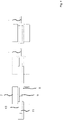
- FIG. 3 shows a schematic representation of elements of an arrangement for an extrusion device for coaxial extrusion, in which the first and second material bolts 8, 9 are formed with different bolt lengths.
- the first material bolt 8 is shorter than the second material bolt 9.
- the length ratio of the first and second material bolts 8, 9 is reversed. The depictions in the 3 and 4 then show from left to right the increasing feed of the first and the second ram 11 in order to produce the extruded product 1.
- the method for hybrid extrusion using the multi-ram system uses, for example, the previously explained double-ram design with the multi-hole recipient or receiver 7 with the at least two bores for the receiver bores 5, 6 in a coaxial arrangement and the corresponding number of individually movable and controllable press rams 10, 11.
- the forming tool 15 is fed by the separate streams of material.
- the mold cavity 14 provides a welding chamber to join the sub-beads of materials through the application of pressure and temperature.
- the rams 10, 11 move the material to be pressed in the material bolts 8, 9, depending on the individual volume flows, either at the same speed or at different speeds in the direction of the mold 15.
- the individual receiver bores 5, 6 and corresponding dummy blocks do not have to have the same diameter.
- the material bolts 8, 9 are moved in a manner comparable to direct extrusion through the receiver bores 5, 6 in the direction of the forming tool 15 (die).
- large parts of the oxides and impurities in the pressing bolts can already be retained.
- the streams of material which feed the mold cavity 14 are already sheared and only contain a small proportion of impurities.
- In the mold cavity 14 flows of material with almost pure metallic surfaces. These are joined in the mold cavity 14 and exit the mold 15 through the press channel as a composite strand (extruded product 1).
- the ram speeds can be adjusted so that, according to the product specification, defined volume shares of the individual composite partners can be realized in the product.
- a defined positioning of the boundary layer is achieved by defining the volume fractions.
- the compression ratios for each material will be different if the sensor geometry is retained. This is taken into account by controlling the bolt length in connection with two press dies that move at different speeds. For this it is necessary that both rams 10, 11 can be moved in a path-controlled manner. In order to be able to control the rams 10, 11 independently, the extrusion press can have a separate hydraulic system for moving the rams 10, 11.
- one or more of the following advantages can be achieved compared to known extrusion methods: thermal and tribological decoupling of the material partners; Adjustability of different bolt application temperatures; Separate control of the flow rates of the material partners; customization of required process variables; and targeted control of the material flows for variable volume ratios (load / function-adapted cross-sections).
- the process enables the production of metallic material composites within a single solid forming step.
- the flow of the material partners with significantly different yield stresses can be adjusted in such a way that over the entire profile length of the extruded product 1 a defined material arrangement (volume ratio of the material partners or wall thickness of the material partners, formation of the boundary layer) can be adjusted.
Landscapes
- Engineering & Computer Science (AREA)
- Mechanical Engineering (AREA)
- Forging (AREA)
- Press-Shaping Or Shaping Using Conveyers (AREA)
Abstract
Description
- Die Erfindung bezieht sich auf ein Verfahren und eine Vorrichtung zum koaxialen Strangpressen eines Strangpressprodukts.
- Das Strangpressen stellt im Bereich der Massivumformung eine energieeffiziente Möglichkeit dar, aus Vormaterial mittels nur eines Umformschritts als Strangpressprodukt insbesondere endkonturnahe Halbzeuge herzustellen. Verschiedene Werkstoffe können verarbeitet werden. Neben Leichtmetallen wie Aluminium, Magnesium und Titan lassen sich zum Beispiel auch Eisenmetalle, Buntmetalle und Edelmetalle sowie deren Legierungen in Form bringen. Die Prozesstemperaturen können hierbei bis zu etwa 1300 °C betragen, können aber auch unterhalb 0 °C liegen. Das Verfahren ermöglicht es, engste Formtoleranzen einzuhalten und darüber hinaus über die Mikrostruktur die chemischen und physikalischen Eigenschaften der Pressprodukte den spezifischen Anforderungen der Endprodukte anzupassen. Als Ausgangmaterial eignen sich außer Gussvormaterial beispielweise auch Schmiedezwischenprodukte und Pulverwerkstoffe.
- Den immer umfangreicheren Anforderungsprofilen für Struktur- und Funktionsbauteile sowohl im Automotive- als auch im Transport-, Energie-, Medizin- und Luftfahrtbereich wird zunehmend mit belastungsangepassten Konzepten begegnet. Dazu gehören neben querschnittsoptimierten Geometrien auch vermehrt Hybridkonzepte, in denen unterschiedliche Werkstoffe oder Legierungen lokale Anwendung im Bauteil finden. Allen diesen Konzepten gemein ist die Notwendigkeit eines zusätzlichen Fügeprozesses für die Herstellung einer stoff-, kraft- oder formschlüssigen Verbindung. Diese findet entweder vor oder im Anschluss an die endkonturnahe Formgebung statt.
- Um Metalle stoffschlüssig miteinander zu verbinden, müssen die reinen Metalloberflächen einander bis auf einen Atomabstand angenähert werden. Hierbei müssen sowohl ein ausreichend hoher Druck als auch eine ausreichend hohe Temperatur herrschen, um die Oberflächenrauheit einzuebnen und die nötige Annäherung zu erzeugen sowie die für die chemische Bindung notwendigen Diffusionsvorgänge zu ermöglichen. Da Metalloberflächen im Allgemeinen mit Verunreinigungen und Oxiden belegt sind, müssen die "reinen" Oberflächen zunächst freigelegt werden, um eine Verbindung auf atomarer Ebene erzeugen zu können. Damit dies gelingt, müssen die Berührungsflächen der beiden Metallvolumina in hinreichendem Maße vergrößert werden. Die Deckschichten dürfen sich jedoch nicht bzw. im Verhältnis zur Berührungsfläche nur in sehr geringem Maß vergrößern.
- Eine Möglichkeit die Oberflächen von Fügepartnern aufzureißen besteht darin, diese unter Einfluss von Normalspannungen aneinander zu scheren. Hierbei wird die Oberfläche durchgeknetet und dadurch vergrößert, wodurch die Verunreinigungen und Oxide aufreißen, so dass die reine Metalloberfläche freigelegt wird. In Abhängigkeit von der Höhe der eingebrachten Scherung lassen sich einerseits die Verunreinigungen und Oxide stark zerkleinern und andererseits die Oberfläche signifikant vergrößern.
- Das Strangpressen bietet grundsätzlich die Möglichkeit, getrennte Materialströme während der Formgebung miteinander zu "verpressen" und dadurch im Strangpressprodukt eine Fügeverbindung, die sogenannte Strangpressnaht bzw. Pressnaht, zu erzeugen. Die hierfür nötigen Temperaturen und Drücke sowie eine ausreichende Scherung können mittels Strangpressprozess eingebracht werden. Auf diese Weise lassen sich unterschiedliche Werkstoffe und Legierungen während des Strangpressens verbinden. In verschiedenen Arbeiten wurde das Strangpressen von Verbunden aus unterschiedlichen metallischen Materialien untersucht und der Einfluss der Prozessgrößen auf die Verbundeigenschaften dargestellt. Auch am Forschungszentrum Strangpressen wurden in der Vergangenheit Untersuchungen zum Strangpressen von Werkstoffverbunden durchgeführt (vgl. Negendank et al., J. Mater Process Tech 212, 2012, 1954; Negendank et al., Key Enginneering Materials 554-557, 2013, 767; Nitschke et al., Magnesium - 10th International Conference on Magnesium alloys and their applications (Editor: K.U. Kainer), 2015, 478). Dabei konnte gezeigt werden, dass sich Werkstoffverbunde mit Hilfe verschiedener Verfahrensvarianten des Strangpressens herstellen lassen.
- Werkstoffverbunde können mittels des Verfahrens des hydrostatischen Strangpressens mit Anwendung eines Wirkmediums hergestellt werden (vgl. Ruppin et al., Aluminium 56, 1980, 523). Hierdurch lässt sich der direkte Kontakt und damit Festkörperreibung zwischen Bolzen, Aufnehmer und Pressstempel verhindern oder vermindern (vgl. Bauser et al., Strangpressen, Aluminium-Verlag, Düsseldorf, 2001). Aus diesem Grund weist das Verfahren einen nahezu idealen Materialfluss auf und ermöglicht beispielsweise die Herstellung von zum Beispiel Cu / AI-Verbunden oder Cu / Nb3Sn-Supraleitern. Der verfahrenstechnisch bedingte Aufwand für die Bolzenvorbereitung (geometrische Anpassung der Bolzenvorderseite zur Abdichtung des Aufnehmerinhaltes in Richtung Matrize) sowie die Versuchsdurchführung (Füllung des Aufnehmers mit dem Hydrostatikmedium, Abdichten und entnehmen nach dem Pressvorgang) sind jedoch sehr arbeits-, zeit- und kostenintensiv.
- Beim Verbundstrangpressen können zylindrische Multi-Material-Bolzen zum Einsatz kommen. Zum Beispiel lassen sich Magnesiumhybride durch Strangpressen formen und fügen. Allerdings führt das Pressen von Legierungspaarungen mit signifikanten Unterschieden in den Umformwiderständen zu erheblichen Schwierigkeiten beim Einstellen eines homogenen Materialflusses, was zu einem ausgeprägten Verzug im Profil führt bis hin zur Degradation des Profils im Bereich der Pressnaht. Ferner können starke Drehungen und Verschiebungen der Grenzfläche relativ zum Profilquerschnitt auftreten. Diese Effekte können von den jeweiligen Volumenanteilen und der Lage der Bolzenteile abhängen (vgl. Nitschke et al., Magnesium - 10th International Conference on Magnesium alloys and their applications (Editor: Kainer), 2015, 478).
- In Verbindung mit dem koaxialen Strangpressen von Aluminium-Magnesiumverbunden wurde gezeigt, dass mittels Strangpressen Verbunde aus Magnesium und Aluminium geformt und gefügt werden können (vgl. Negendank et al., J.Mater Process Tech 212, 2012, 1954; Negendank et al., Key Enginneering Materials 554-557, 2013, 767).
- Aufgabe der Erfindung ist es, ein Verfahren und eine Vorrichtung zum koaxialen Strangpressen eines Strangpressprodukts zu schaffen, mit denen Strangpressprodukte effizienter und variabler herstellbar sind.
- Zur Lösung sind ein Verfahren sowie eine Vorrichtung zum koaxialen Strangpressen eines Strangpressprodukts nach den unabhängigen Ansprüchen 1 und 13 geschaffen. Ausgestaltungen sind Gegenstand von abhängigen Unteransprüchen.
- Nach einem Aspekt ist ein Verfahren zum Herstellen eines Strangpressprodukts geschaffen. Hierbei wird eine Strangpressvorrichtung bereitgestellt, die Folgendes aufweist: einen Aufnehmer; eine erste Aufnehmerbohrung, die in dem Aufnehmer gebildet und in der ein erster Pressstempel angeordnet ist; eine zweite Aufnehmerbohrung, die in dem Aufnehmer innerhalb der ersten Aufnehmerbohrung und koaxial hierzu gebildet und in der ein zweiter Pressstempel angeordnet ist; und ein Formwerkzeug mit einem Formhohlraum, welcher mit der ersten und der zweiten Aufnehmerbohrung verbunden sind. Bei dem Verfahren ist weiterhin Folgendes vorgesehen: Anordnen eines ersten Werkstoffbolzens aus einem ersten Werkstoff in der ersten Aufnehmerbohrung; Anordnen eines zweiten Werkstoffbolzens aus einem zweiten Werkstoff in der zweiten Aufnehmerbohrung; und Strangpressen eines Strangpressprodukts, bei dem der erste und der zweite Werkstoff form- und stoffschlüssig verbunden sind. Das Strangpressen umfasst hierbei weiterhin Folgendes: Vorschieben des ersten Pressstempels in der ersten Aufnehmerbohrung, derart, dass hierdurch der erste Werkstoff in den Formhohlraum des Formwerkzeugs gepresst und hierbei umgeformt wird; Vorschieben des zweiten Pressstempels in der zweiten Aufnehmerbohrung, derart, dass hierdurch der zweite Werkstoff in den Formhohlraum des Formwerkzeugs gepresst und hierbei umgeformt wird; und stoff- und formschlüssiges Verbinden des ersten und des zweiten Werkstoffs zu einem Strangpressprodukt in dem Formwerkzeug.
- Nach einem weiteren Aspekt ist eine Vorrichtung zum koaxialen Strangpressen eines Strangpressprodukts geschaffen, die Folgendes aufweist: einen Aufnehmer; eine erste Aufnehmerbohrung, die in dem Aufnehmer gebildet und in der ein erster Pressstempel angeordnet ist; eine zweite Aufnehmerbohrung, die in dem Aufnehmer innerhalb der ersten Aufnehmerbohrung und koaxial hierzu gebildet und in der ein zweiter Pressstempel angeordnet ist; und ein Formwerkzeug mit einem Formhohlraum, welcher mit der ersten und der zweiten Aufnehmerbohrung in Verbindung steht, derart, dass beim Strangpressen mittels Vorschieben des ersten Pressstempels in der ersten Aufnehmerbohrung und Vorschieben des zweiten Pressstempels koaxial zum ersten Pressstempels in der zweiten Aufnehmerbohrung ein erster Werkstoff eines ersten Werkstoffbolzens aus der ersten Aufnehmerbohrung und ein zweiter Werkstoff eines zweiten Werkstoffbolzens aus der zweiten Aufnehmerbohrung zum Herstellen eines Strangpressprodukts, bei dem der erste und der zweite Werkstoff form- und stoffschlüssig verbunden sind, in dem Formhohlraum einbring-bar ist.
- Das Vorsehen der mindestens zwei Pressstempel, die in voneinander getrennten Aufnehmerbohrungn angeordnet sind, ermöglicht es, die Pressstempel beim Strangpressen unabhängig voneinander zu betreiben, um mittels Vorschub den jeweiligen Werkstoff in dem Formwerkzeug einzubringen.
- Die Bewegung der Pressstempel beim Vorschieben erfolgt in den zugeordneten Aufnehmerbohrungn koaxial. Die Aufnehmerbohrungn können endseitig direkt an den Formhohlraum des Formwerkzeugs koppeln, so dass der Werkstoff aus einem Ausgang der Aufnehmerbohrung direkt in einen Eingang des Formhohlraums gelangt. Die Aufnehmerbohrungn bilden jeweils einen Presskanal, entlang welchem der Werkstoff mit Pressdruck beaufschlagt wird, um diesen aus der Aufnehmerbohrung in dem Formwerkzeug einzubringen und hierbei umzuformen.
- Die Aufnehmerbohrungn können mit einer Zylinderform gebildet sein.
- Beim Strangpressen werden die Werkstoffe in dem Formwerkzeug entlang einer Fügeverbindung (Fügenaht) stoff- und formschlüssig verbunden.
- Bei den Werkstoffen kann es sich um metallische Werkstoffe unterschiedlicher Art handeln, zum Beispiel Aluminium oder Magnesium.
- Die Ausbildung getrennter Aufnehmerbohrungn mit jeweiligem Pressstempel ermöglicht voneinander entkoppelte Vorschubbewegungen der Pressstempel in den Aufnehmerbohrungn.
- Das stoff- und formschlüssige Verbinden kann in dem Formwerkzeug zwischen dem ersten und dem zweiten Werkstoff ausgeführt werden. Mittels der aufeinander entkoppelten Vorschubbewegung der Pressstempel in den getrennten Aufnehmerbohrungn kann die Scherspannung zwischen dem ersten und dem zweiten Werkstoff in dem Formhohlraum eingestellt und variiert werden.
- Der erste und der zweite Werkstoff können mit unterschiedlicher Relativgeschwindigkeit in dem Formhohlraum eingebracht werden. Die Einstellbarkeit unterschiedlicher Relativgeschwindigkeiten ermöglicht eine Anpassung des Strangpressprozesses an unterschiedliche Werkstoffe. Auch kann der Herstellungsprozess so für die Anforderungen bei verschiedenen Strangpressprodukten optimiert werden.
- Ein erster Vorschub beim Vorschieben des ersten Pressstempels in der ersten Aufnehmerbohrung und ein zweiter Vorschub beim Vorschieben des zweiten Pressstempels in der zweiten Aufnehmerbohrung können unabhängig voneinander geregelt werden. Die voneinander entkoppelte Einstell- oder Regelbarkeit des Vorschubs der Pressstempel in den getrennten Aufnehmerbohrungen ermöglicht eine individuelle Anpassung oder Lenkung des Strangpressprozesses an verschiedene Prozessführungen, beispielweise in Abhängigkeit von den Werkstoffen und / oder dem herzustellenden Strangpressprodukt.
- Das Vorschieben des ersten Pressstempels in der ersten Aufnehmerbohrung kann mit einer ersten Vorschubgeschwindigkeit und das Vorschieben des zweiten Pressstempels in der zweiten Aufnehmerbohrung kann mit einer zweiten Vorschubgeschwindigkeit ausgeführt werden, die von der ersten Vorschubgeschwindigkeit verschieden ist. Mittels unterschiedlicher Vorschubgeschwindigkeiten können insbesondere die Relativgeschwindigkeiten für die Werkstoffe beim Übergang aus der Aufnehmerbohrung in den Formhohlraum des Formwerkzeugs eingestellt werden.
- Der erste Pressstempel kann beim Bewegen in der ersten Aufnehmerbohrung mittels eines ersten Aktors und der zweite Pressstempel kann beim Bewegen in der zweiten Aufnehmerbohrung mittels eines zweiten Aktors angetrieben werden, welcher getrennt von dem ersten Aktor gebildet und steuerbar ist. Alternativ kann vorgesehen sein, die Presstempel mit einem Aktor zu betätigen, der den Pressstempeln gemeinsam zugeordnet ist. Der gemeinsame Aktor kann entkoppelte Aktorelemente aufweisen, die eine entkoppelte Vorschubbewegung der Presstempel bewirken können.
- Als zweiter Werkstoff kann ein Werkstoff verwendet werden, welcher von dem ersten Werkstoff verschieden ist. Beispielsweise können verschiedene metallische Werkstoffe zum Einsatz kommen.
- Für den ersten und den zweiten Werkstoff kann der gleiche Werkstoff verwendet werden.
- Als Strangpressprodukt kann ein Strangpressprofil hergestellt werden. Das Strangpressprofil kann mit beliebigen Profilquerschnitten hergestellt werden. Mittels des Verfahrens lassen sich Strangpressprofile mit axial veränderlichen Volumenanteilen unterschiedlicher Werkstoffe herstellen. Darüber hinaus lassen sich mit geeigneten Matrizenkonstruktionen Strangpressprodukte mit axial veränderlichem Querschnitt und gleichzeitig axial veränderlichen Volumenanteilen unterschiedlicher Werkstoffe herstellen.
- Es kann eine Strangpressvorrichtung bereitgestellt sein, bei der die zweite Aufnehmerbohrung in einem inneren Hohlraum des ersten Pressstempels angeordnet ist. Die Aufnehmerbohrungen können bei dieser oder anderen Ausführungsformen mit runden, eckigen oder ovalen Querschnitt gebildet sein, insbesondere kreisrund oder verschiedene von kreisrund.
- Es kann eine Strangpressvorrichtung bereitgestellt sein, bei der die zweite Aufnehmerbohrung von dem inneren Hohlraum des ersten Pressstempels gebildet wird und der zweite Pressstempel formschlüssig in dem inneren Hohlraum aufgenommen ist.
- Es kann eine Strangpressvorrichtung bereitgestellt sein, bei der die zweite Aufnehmerbohrung mittels eines Hülsenbauteils gebildet ist, welches in dem inneren Hohlraum des ersten Pressstempels angeordnet ist, und der zweite Pressstempel formschlüssig im Innenraum des Hülsenbauteils aufgenommen ist.
- Es kann eine Strangpressvorrichtung bereitgestellt werden, bei der die erste Aufnehmerbohrung und die zweite Aufnehmerbohrung gegeneinander abgedichtet sind. Die Aufnehmerbohrungen können hierbei fluiddicht gegeneinander abgedichtet sein, insbesondere Flüssigkeitsdicht.
- Die Aufnehmerbohrungen bilden eine jeweilige Aufnahme für den Pressstempel (Stempelaufnahme).
- Die vorangehend in Verbindung mit dem Verfahren zum koaxialen Strangpressen eines Strangpressprodukts erläuterten Ausgestaltungen können in Verbindung mit der Vorrichtung zum koaxialen Strangpressen entsprechend vorgesehen sein.
- Mittels der vorgeschlagenen Technik kann in einer Ausgestaltung vorgesehen sein, dass die einzelnen Materialströme den Formhohlraum homogen speisen, sodass innerhalb des Formhohlraums und im Bereich des Presskanals möglichst wenig Scherung in Pressrichtung erzeugt wird. Hierdurch lassen sich die Kontaktschubspannungen und auch die axialen Dehnungsdifferenzen zwischen den Werkstoffpartnern beim Fügeprozess minimieren. Es wird eine homogene Strangaustrittsgeschwindigkeit über den gesamten Querschnitt erzielt und eine schädigende Scherung im Bereich der Grenzschicht wird verhindert. In anderen Worten bedeutet das, dass Materialströme mit gleicher Fließgeschwindigkeit in dem Formhohlraum zusammen gebracht und diese durch einen Mindestdruck aneinander pressbar sind, um ein stoffschlüssiges Hybrid (Strangpressprodukt) zu erzeugen.
- So können in einer Ausführungsform lokal gleich schnelle Materialströme mit unterschiedlichen Pressmaterialien realisiert werden, welche abweichende Umformwiderstände und Prozessfenster aufweisen. Bei der Anwendung einer klassischen Strangpresse mit nur einem Pressstempel ist dies nicht realisierbar Insbesondere ist es bei der Anwendung der klassischen Strangpresse mit nur einem Pressstempel nicht möglich, den Druck in den Bereichen primäre Umformzone, Schweißkammer und Presskanal auf gleichem Niveau einzustellen, um die Grenzschichtverschiebung zu verhindern.
- Es kann vorgesehen sein, beim Herstellen des Strangpressprodukts den Querschnitt von stranggepressten Verbundprofilen entsprechend den im Einsatz vorherrschenden Belastungen auf Bauteile und Komponenten lokal anzupassen. Beispielsweise kann vorgesehen sein, die Wandstärke eines für eine Lastaufnahme beim Strangpressprodukt verantwortlichen Werkstoffs in ersten Bereichen dickwandiger auszuführen als in schwächer belasteten Regionen (zweite Bereiche, die von den ersten Bereichen verschieden sind), die dann mit einer geringeren Wandstärke ausgeführt werden. Die Entwicklung von belastungsangepassten, maßgeschneiderten Profilen kann das Gewicht von stranggepressten Komponenten oder Bauteilen gegenüber solchen, die über den konventionellen Herstellungsprozess erzeugt wurden, vermindern.
- Im Folgenden werden weitere Ausführungsbeispiele unter Bezugnahme auf Figuren einer Zeichnung erläutert. Hierbei zeigen:
- Fig. 1
- eine schematische Darstellung einer Vorrichtung zum Herstellen eines Strangpressprodukts;
- Fig. 2
- eine perspektivische Darstellung eines Aufnehmers für eine Strangpressvorrichtung im Aufriss, bei dem ein erster und ein zweiter Presstempel einer koaxialen Anordnung entsprechend in einer ersten und einer zweiten Aufnehmerbohrung angeordnet sind;
- Fig. 3
- eine schematische Darstellung einer Anordnung mit zwei Pressstempeln zum Pressen von unterschiedlich langen Werkstoffbolzen im Schnitt und
- Fig. 4
- eine schematische Darstellung einer weiteren Anordnung mit zwei Pressstempeln zum Pressen von unterschiedlich langen Werkstoffbolzen im Schnitt.
-
Fig. 1 zeigt eine schematische Darstellung einer Vorrichtung zum Herstellen eines Strangpressprodukts 1 mittels koaxialem Strangpressen im Schnitt. Bei dem Strangpressprodukt 1 sind ein erster Werkstoff 2 und ein zweiter Werkstoff 3 entlang einer umlaufenden Fügeverbindung oder -naht 4 form- und stoffschlüssig mittels Strangpressen miteinander verbunden sind, derart, dass der zweite Werkstoff 3 axial umlaufend vom dem ersten Werkstoff 2 umgeben ist. Bei dem Strangpressprodukt 1 kann es sich um ein Strangpressprofil handeln. - Die Formulierungen "Strangpressprofil" und "Strangpressprodukt" in den hier verwendeten Bedeutungen umfassen alle mit Hilfe des Strangpressprozesses herstellbaren Profilgeometrien. Hierzu zählen zum Beispiel sowohl Vollprofile als auch Hohlprofile sowie Halbhohlprofile in beliebigen Geometrien. So sind als Strangpressprofile beispielweise stranggepresste "Bleche" ebenso wie Rohre, Fensterprofile oder Rundstangen bekannt.
- Zum Herstellen des Strangpressprodukts 1 sind in einer ersten und einer zweiten Aufnehmerbohrung 5, 6 eines Aufnehmers 7 ein erster Werkstoffbolzen 8 aus dem ersten Werkstoff 2 und ein zweiter Werkstoffbolzen 9 aus dem zweiten Werkstoff 3 angeordnet. Die erste und die zweite Aufnehmerbohrung 5, 6 stellen einen jeweiligen Kanal mit einer Zylinderform zur Verfügung, der einen runden, eckigen oder ovalen Querschnitt aufweisen kann. In den Aufnehmerbohrungen 5, 6 sind ein erster und ein zweiter Pressstempel 10, 11 angeordnet, die jeweils in axialer Richtung und hierbei zueinander koaxial in der zugeordneten Aufnehmerbohrung 5, 6 verschiebbar sind.
- Der erste Pressstempel 10 ist als Hohlbauteil ausgeführt und umgibt die zweite Aufnehmerbohrung 6, wenn er in die erste Aufnehmerbohrung eingeführt ist. Eine Wandung 6a, die die zweite Aufnehmerbohrung 6 begrenzt und deren Innenseite der zweiten Aufnehmerbohrung 6 zugewandt ist, kann als getrennte Wand zwischen der ersten und der zweiten Aufnehmerbohrung 5, 6 ausgeführt sein. Alternativ, kann die zweite Aufnehmerbohrung 6 mittels eines Hohlraums in dem ersten Pressstempel 10 gebildet sein. In diesem Fall kann der zweite Pressstempel 11 beim Vorschub in dem Hohlraum des ersten Pressstempels 10 gleiten oder rutschen.
- Dem ersten und dem zweiten Pressstempel 10, 11 sind ein erster und ein zweiter Aktor 12, 13 zugeordnet, welche eingerichtet sind, den jeweiligen Pressstempel 10, 11 mit Kraft zu beaufschlagen, so dass die Pressstempel 10, 11 eine koaxiale Vorschubbewegung in Richtung eines Formhohlraums 14 eines Formwerkzeugs 15 ausführen, um so den ersten und den zweiten Werkstoff 2, 3 in dem Formhohlraum 14 einzubringen. Hierzu stehen die erste und die zweite Aufnehmerbohrung 5, 6 mit dem Formhohlraum 14 in Verbindung, derart, dass das Material des ersten und des zweiten Werkstoffbolzens 8, 9 in dem Formhohlraum 14 eingebracht und hierbei umgeformt wird. Die Druckbeaufschlagung führt dazu, dass in dem Formhohlraum 14 die Fügeverbindung 4 zwischen den ersten und dem zweiten Werkstoff 2, 3 ausgebildet wird.
- Gemäß der schematischen Darstellung in
Fig. 1 ist der erste Aktor 12 zweiteilig oder -stückig gezeigt. Es kann sich jedoch um einen einzigen ersten Aktor handeln. - Mit Hilfe des ersten und des zweiten Aktors 12, 13, können der erste und der zweite Pressstempel 10, 11 voneinander entkoppelte Vorschubbewegungen beim Strangpressen ausführen. Insbesondere können sich der erste und der zweite Pressstempel 10, 11 mit unterschiedlicher Geschwindigkeit beim Vorschub bewegen. Mit Hilfe der unabhängigen Einstellung der beiden Vorschubbewegungen ist es ermöglicht, für den Übergang des ersten und des zweiten Werkstoffs 2, 3 in den Formhohlraum 14 unterschiedliche Fließgeschwindigkeiten einzustellen. Der erste und der zweite Werkstoff 2, 3, die einen außenliegenden und einen innenliegenden Werkstoff bilden, können zum Beispiel unterschiedliche metallische Werkstoffe sein, aber auch die Verwendung gleicher metallischer Werkstoffe für die beiden Werkstoffbolzen 8, 9 kann vorgesehen sein. Das erzeugte Strangpressprodukt 1 kann ein Strangpressprofil sein.
- Weitere Ausführungsbeispiele werden nachfolgend unter Bezugnahme auf die
Fig. 2 bis 4 erläutert. Für gleiche Merkmale werden die gleichen Bezugszeichen wie inFig. 1 verwendet. -
Fig. 2 zeigt eine schematische Darstellung einer Anordnung für eine Strangpressvorrichtung zum koaxialen Strangpressen, bei der in der ersten und der zweiten Aufnehmerbohrung 5, 6 der erste und der zweite Pressstempel 10, 11 angeordnet sind. Während der erste Pressstempel 10 als ein Hohlstempel ausgeführt ist, ist der zweite Pressstempel 11 ein Vollmaterialstempel. In dem ersten Pressstempel 10 ist die zweite Aufnehmerbohrung 6 für den zweiten Pressstempel 11 gebildet, derart, dass eine äußere Oberfläche des zweiten Pressstempels 11 und einer innere Oberfläche des ersten Pressstempels 10 einander gegenüberliegend und in Kontakt angeordnet sind. - Eine formschlüssige Abdichtung kann mittels einer zwischen Pressstempel 10, 11 und Werkstoffbolzen 8, 9 positionierte sogenannte "Pressscheibe" (nicht dargestellt). Diese findet sowohl fest - im Sinne von "konstruktiv temporär miteinander verbunden, jedoch austauschbar" - als auch lose Verwendung.
-
Fig. 3 zeigt eine schematische Darstellung von Elementen einer Anordnung für eine Strangpressvorrichtung zum koaxialen Strangpressen, bei der der erste und der zweite Werkstoffbolzen 8, 9 mit unterschiedlicher Bolzenlänge gebildet sind. Bei der inFig. 3 gezeigten Ausführung ist der erste Werkstoffbolzen 8 kürzer als der zweite Werkstoffbolzen 9. In einer weiteren Ausführung gemäßFig. 4 ist das Längenverhältnis von erstem und zweitem Werkstoffbolzen 8, 9 umgekehrt. Die Darstellungen in denFig. 3 und4 zeigen dann von links nach rechts den zunehmenden Vorschub des ersten und des zweiten Pressstempels 11, um das Strangpressprodukt 1 herzustellen. - Nachfolgend werden Aspekte zu weiteren Ausführungsbeispielen erläutert.
- Das Verfahren zum Hybridstrangpressen mittels des Mehrstempelsystems nutzt zum Beispiel die vorangehend erläuterte Zweifachstempel-Ausführung mit dem Mehrlochrezipienten oder -aufnehmer 7 mit den mindestens zwei Bohrungen für die Aufnehmerbohrungen 5, 6 in koaxialer Anordnung und der entsprechenden Anzahl individuell verfahrbarer und steuerbarer Pressstempel 10, 11. Das Formwerkzeug 15 (Strangpressmatrize) wird durch die getrennten Materialströme gespeist. Der Formhohlraum 14 stellt eine Schweißkammer bereit, um die Teilstränge der Werkstoffe durch Einwirkung von Druck und Temperatur zu fügen.
- Die Pressstempel 10, 11 bewegen das Pressgut in den Werkstoffbolzen 8, 9 in Abhängigkeit von den individuellen Volumenströmen entweder gleich schnell oder mit unterschiedlichen Geschwindigkeiten in Richtung des Formwerkzeug 15. Die einzelnen Aufnehmerbohrungen 5, 6 und entsprechenden Pressscheiben müssen nicht dieselben Durchmesser aufweisen.
- Bei dem Verfahren werden die Werkstoffbolzen 8, 9 vergleichbar mit dem direkten Strangpressen durch die Aufnehmerbohrungen 5, 6 hindurch in Richtung des Formwerkzeugs 15 (Matrize) bewegt. Hierbei können aufgrund der Relativbewegung zwischen den Innenwänden der Aufnehmerbohrungen 5, 6 und den Mantelflächen der Werkstoffbolzen 8, 9 bereits große Teile der Oxide und Verunreinigungen der Pressbolzen zurückgehalten werden. Die Materialströme, welche den Formhohlraum 14 speisen, sind bereits geschert und enthalten nur noch einen geringen Teil an Verunreinigungen. In den Formhohlraum 14 Materialströme mit nahezu reinen metallischen Oberflächen ein. Diese werden in dem Formhohlraum 14 gefügt und treten als Verbundstrang (Strangpressprodukt 1) durch den Presskanal aus dem Formwerkzeug 15 aus.
- In Abhängigkeit der für die einzelnen Materialströme vorgesehenen individuellen Pressverhältnisse können die Stempelgeschwindigkeiten angepasst werden, sodass, entsprechend der Produktvorgabe, definierte Volumenanteile der einzelnen Verbundpartner im Produkt realisiert werden können. Gleichzeitig wird durch die Festlegung der Volumenanteile eine definierte Positionierung der Grenzschicht erzielt.
- Für den Fall des Pressens bei gleicher Geschwindigkeit beider Pressstempel 10, 11 und konstanter Bolzenlänge wird ein Profil gepresst, in dem die Verbundmaterialien in gleichem Verhältnis symmetrisch nebeneinander ausgepresst werden. Durch eine gezielt einstellbare Temperaturdifferenz zwischen beiden Werkstoffbolzen 5, 6 können Verbundflachprofile sowohl aus Materialpaarungen mit geringen als auch mit großen Unterschieden im Umformwiderstand aus separaten Containern hergestellt werden.
- Für den Fall, dass beide Werkstoffe 2, 3 in unterschiedlich großen Volumenanteilen im Strangpressprodukt 1 vorliegen sollen, ergeben sich bei Beibehaltung der Aufnehmergeometrie für jeden Werkstoff (Hybridpartner) unterschiedliche Pressverhältnisse. Dem wird durch Lenkung der Bolzenlänge in Verbindung mit zwei unterschiedlich schnell verfahrenden Pressstempeln Rechnung getragen. Dazu ist es erforderlich, dass sich beide Presstempel 10, 11 weggesteuert verfahren lassen. Um die Presstempel 10, 11 autark steuern zu können, kann die Strangpresse ein separates Hydrauliksystem für die Bewegung des Presstempel 10, 11 aufweisen.
- In den beschriebenen Ausführungsformen können einzelne oder mehrere der folgenden Vorteile gegenüber bekannten Strangpressverfahren erreicht werden: Thermische und tribologische Entkopplung der Werkstoffpartner; Einstellbarkeit unterschiedlicher Bolzeneinsatztemperaturen; Separate Steuerung der Fließgeschwindigkeiten der Werkstoffpartner; individuelle Anpassung der erforderlichen Prozessvariablen; und gezielte Lenkung der Materialströme für variable Volumenverhältnisse (last- / funktionsangepasste Querschnitte).
- Das Verfahren ermöglicht die Herstellung von metallischen Werkstoffverbunden innerhalb eines einzigen Massivumformschritts. Mittels Einsatz von separat steuerbaren Pressstempeln und der Möglichkeit, unterschiedliche Aufnehmerbohrungen (Stempelaufnahmen) zu realisieren, lässt sich das Fließen der Werkstoffpartner mit signifikant unterschiedlichen Fließspannungen derart einstellen, dass über der kompletten Profillänge des Strangpressprodukts 1 ein definierte Werkstoffanordnung (Volumenverhältnis der Werkstoffpartner bzw. Wandstärke der Werkstoffpartner, Ausbildung der Grenzschicht) einstellbar ist.
- Die in der vorstehenden Beschreibung, den Ansprüchen sowie der Zeichnung offenbarten Merkmale können sowohl einzeln als auch in beliebiger Kombination für die Verwirklichung der verschiedenen Ausführungen von Bedeutung sein.
Claims (13)
- Verfahren zum koaxialen Strangpressen eines Strangpressprodukts, mit- Bereitstellen einer Strangpressvorrichtung, aufweisend- einen Aufnehmer (7);- eine erste Aufnehmerbohrung (5), die in dem Aufnehmer (7) gebildet und in der ein erster Pressstempel (10) angeordnet ist;- eine zweite Aufnehmerbohrung (6), die in dem Aufnehmer (7) innerhalb der ersten Aufnehmerbohrung (5) und koaxial hierzu gebildet und in der ein zweiter Pressstempel (11) angeordnet ist; und- ein Formwerkzeug (15) mit einem Formhohlraum (14), welcher mit der ersten und der zweiten Aufnehmerbohrung (5, 6) verbunden sind;- Anordnen eines ersten Werkstoffbolzens (8) aus einem ersten Werkstoff (2) in der ersten Aufnehmerbohrung (5);- Anordnen eines zweiten Werkstoffbolzens (9) aus einem zweiten Werkstoff (3) in der zweiten Aufnehmerbohrung (6); und- Strangpressen eines Strangpressprodukts (1), bei dem der erste und der zweite Werkstoff (2, 3) form- und stoffschlüssig verbunden sind, Folgendes aufweisend:- Vorschieben des ersten Pressstempels (10) in der ersten Aufnehmerbohrung (5), derart, dass hierdurch der erste Werkstoff (2) in den Formhohlraum (14) des Formwerkzeugs (15) gepresst und hierbei umgeformt wird;- Vorschieben des zweiten Pressstempels (11) in der zweiten Aufnehmerbohrung (6), derart, dass hierdurch der zweite Werkstoff (3) in den Formhohlraum (14) des Formwerkzeugs (15) gepresst und hierbei umgeformt wird, wobei der zweite Pressstempel (11) hierbei koaxial zum ersten Presstempel (10) verlagert wird; und- stoff- und formschlüssiges Verbinden des ersten und des zweiten Werkstoffs zu einem Strangpressprodukt (1) in dem Formwerkzeug (15), derart, dass bei dem Strangpressprodukt (1) der erste Werkstoff (2) den zweiten Werkstoff (3) umgibt.
- Verfahren nach Anspruch 1, dadurch gekennzeichnet, dass das stoff- und formschlüssige Verbinden in dem Formwerkzeug (15) zwischen dem ersten und dem zweiten Werkstoff (2, 3) ausgeführt wird.
- Verfahren nach Anspruch 1 oder 2, dadurch gekennzeichnet, dass der erste und der zweite Werkstoff (2, 3) mit unterschiedlicher Relativgeschwindigkeit in dem Formhohlraum (14) eingebracht werden.
- Verfahren nach mindestens einem der vorangehenden Ansprüche, dadurch gekennzeichnet, dass ein erster Vorschub beim Vorschieben des ersten Pressstempels (10) in der ersten Aufnehmerbohrung (5) und ein zweiter Vorschub beim Vorschieben des zweiten Pressstempels (11) in der zweiten Aufnehmerbohrung (6) unabhängig voneinander eingestellt werden.
- Verfahren nach mindestens einem der vorangehenden Ansprüche, dadurch gekennzeichnet, dass das Vorschieben des ersten Pressstempels (10) in der ersten Aufnehmerbohrung (5) mit einer ersten Vorschubgeschwindigkeit und das Vorschieben des zweiten Pressstempels (11) in der zweiten Aufnehmerbohrung (6) mit einer zweiten Vorschubgeschwindigkeit ausgeführt werden, die von ersten Vorschubgeschwindigkeit verschieden ist.
- Verfahren nach mindestens einem der vorangehenden Ansprüche, dadurch gekennzeichnet, dass der erste Pressstempel (10) beim Bewegen in der ersten Aufnehmerbohrung (5) mittels eines ersten Aktors (12) und der zweite Pressstempel (11) beim Bewegen in der zweiten Aufnehmerbohrung (6) mittels eines zweiten Aktors (13) angetrieben wird, welcher getrennt von dem ersten Aktor (12) gebildet und steuerbar ist.
- Verfahren nach mindestens einem der vorangehenden Ansprüche, dadurch gekennzeichnet, dass als zweiter Werkstoff (3) ein Werkstoff verwendet wird, welcher von dem ersten Werkstoff (2) verschieden ist.
- Verfahren nach mindestens einem der Ansprüche 1 bis 6, dadurch gekennzeichnet, dass für den ersten und den zweiten Werkstoff (2, 3) der gleiche Werkstoff verwendet wird.
- Verfahren nach mindestens einem der vorangehenden Ansprüche, dadurch gekennzeichnet, dass als Strangpressprodukt (1) ein Strangpressprofil hergestellt wird.
- Verfahren nach mindestens einem der vorangehenden Ansprüche, dadurch gekennzeichnet, dass eine Strangpressvorrichtung bereitgestellt wird, bei der die zweite Aufnehmerbohrung (6) in einem inneren Hohlraum des ersten Pressstempels (10) angeordnet ist.
- Verfahren nach Anspruch 10, dadurch gekennzeichnet, dass eine Strangpressvorrichtung bereitgestellt wird, bei der die zweite Aufnehmerbohrung (6) von dem inneren Hohlraum des ersten Pressstempels (10) gebildet wird und der zweite Pressstempel (11) formschlüssig in dem inneren Hohlraum aufgenommen ist.
- Verfahren nach Anspruch 10, dadurch gekennzeichnet, dass eine Strangpressvorrichtung bereitgestellt wird, bei der die zweite Aufnehmerbohrung (6) mittels eines Hülsenbauteils gebildet ist, welches in dem inneren Hohlraum des ersten Pressstempels (10) angeordnet ist, und der zweite Pressstempel (11) formschlüssig im Innenraum des Hülsenbauteils aufgenommen ist.
- Vorrichtung zum koaxialen Strangpressen eines Strangpressprodukts, mit- einen Aufnehmer (7);- eine erste Aufnehmerbohrung, die in dem Aufnehmer (7) gebildet und in der ein erster Pressstempel (10) angeordnet ist;- eine zweite Aufnehmerbohrung (6), die in dem Aufnehmer (7) innerhalb der ersten Aufnehmerbohrung (5) und koaxial hierzu gebildet und in der ein zweiter Pressstempel (11) angeordnet ist; und- ein Formwerkzeug (15) mit einem Formhohlraum (14), welcher mit der ersten und der zweiten Aufnehmerbohrung (5, 6) in Verbindung steht, derart, dass beim Strangpressen mittels Vorschieben des ersten Pressstempels (10) in der ersten Aufnehmerbohrung (5) und Vorschieben des zweiten Pressstempels (11) koaxial zum ersten Pressstempels (10) in der zweiten Aufnehmerbohrung (6) ein erster Werkstoff (2) eines ersten Werkstoffbolzens (8) aus der ersten Aufnehmerbohrung (5) und ein zweiter Werkstoff (3) eines zweiten Werkstoffbolzens (9) aus der zweiten Aufnehmerbohrung (6) zum Herstellen eines Strangpressprodukts (1), bei dem der erste und der zweite Werkstoff (2, 3) form- und stoffschlüssig verbunden sind, in dem Formhohlraum (14) einbringbar ist.
Priority Applications (3)
| Application Number | Priority Date | Filing Date | Title |
|---|---|---|---|
| EP20213457.3A EP4011515B1 (de) | 2020-12-11 | 2020-12-11 | Verfahren und vorrichtung zum koaxialen strangpressen eines strangpressprodukts |
| US18/266,349 US20240042667A1 (en) | 2020-12-11 | 2021-12-09 | Method and device for coaxially extruding an extruded product |
| PCT/EP2021/085044 WO2022122951A1 (de) | 2020-12-11 | 2021-12-09 | Verfahren und vorrichtung zum koaxialen strangpressen eines strangpressprodukts |
Applications Claiming Priority (1)
| Application Number | Priority Date | Filing Date | Title |
|---|---|---|---|
| EP20213457.3A EP4011515B1 (de) | 2020-12-11 | 2020-12-11 | Verfahren und vorrichtung zum koaxialen strangpressen eines strangpressprodukts |
Publications (2)
| Publication Number | Publication Date |
|---|---|
| EP4011515A1 true EP4011515A1 (de) | 2022-06-15 |
| EP4011515B1 EP4011515B1 (de) | 2023-11-22 |
Family
ID=73834303
Family Applications (1)
| Application Number | Title | Priority Date | Filing Date |
|---|---|---|---|
| EP20213457.3A Active EP4011515B1 (de) | 2020-12-11 | 2020-12-11 | Verfahren und vorrichtung zum koaxialen strangpressen eines strangpressprodukts |
Country Status (3)
| Country | Link |
|---|---|
| US (1) | US20240042667A1 (de) |
| EP (1) | EP4011515B1 (de) |
| WO (1) | WO2022122951A1 (de) |
Families Citing this family (2)
| Publication number | Priority date | Publication date | Assignee | Title |
|---|---|---|---|---|
| CN119261148B (zh) * | 2024-08-09 | 2025-03-28 | 高邮亚普塑业有限公司 | 一种医用高分子材料加工的挤出装置及其挤出方法 |
| CN121607428A (zh) * | 2026-01-30 | 2026-03-06 | 太原理工大学 | 一种新型双层挤压杆结构 |
Citations (6)
| Publication number | Priority date | Publication date | Assignee | Title |
|---|---|---|---|---|
| JPS6072610A (ja) * | 1983-09-20 | 1985-04-24 | メリス セミヨ−ノヴイチ ギルジエンゴルン | 金属張合わせ中空製品を製造する方法 |
| JPH04157014A (ja) * | 1990-10-15 | 1992-05-29 | Showa Alum Corp | 金属複合材の製造方法 |
| JPH0760340A (ja) * | 1993-08-31 | 1995-03-07 | Showa Alum Corp | 高力系アルミニウム合金製中空材の押出方法 |
| US20040074275A1 (en) * | 2000-11-01 | 2004-04-22 | In-Tai Jin | Hot metal extru-bending machine |
| DE102004029588A1 (de) * | 2004-06-18 | 2006-01-12 | Gkss-Forschungszentrum Geesthacht Gmbh | Verfahren zur Herstellung von Profilen aus Magnesiumwerkstoffen |
| EP1693124A1 (de) * | 2005-02-22 | 2006-08-23 | Hoesch Schwerter Profile GmbH | Verfahren zur Herstellung metallischer Verbundblöcke |
Family Cites Families (4)
| Publication number | Priority date | Publication date | Assignee | Title |
|---|---|---|---|---|
| US253822A (en) * | 1882-02-14 | Jean baptistb java mignon | ||
| US830201A (en) * | 1902-11-18 | 1906-09-04 | Andre Blondel | Press for manufacturing arc-lamp electrodes. |
| US3457760A (en) * | 1966-12-16 | 1969-07-29 | Reynolds Metals Co | Extrusion of composite metal articles |
| DE102007050291B4 (de) * | 2007-10-22 | 2010-04-08 | Cincinnati Extrusion Gmbh | Extrusionswerkzeug und Verfahren zum Extrudieren von Kunststoffprofilen |
-
2020
- 2020-12-11 EP EP20213457.3A patent/EP4011515B1/de active Active
-
2021
- 2021-12-09 WO PCT/EP2021/085044 patent/WO2022122951A1/de not_active Ceased
- 2021-12-09 US US18/266,349 patent/US20240042667A1/en not_active Abandoned
Patent Citations (6)
| Publication number | Priority date | Publication date | Assignee | Title |
|---|---|---|---|---|
| JPS6072610A (ja) * | 1983-09-20 | 1985-04-24 | メリス セミヨ−ノヴイチ ギルジエンゴルン | 金属張合わせ中空製品を製造する方法 |
| JPH04157014A (ja) * | 1990-10-15 | 1992-05-29 | Showa Alum Corp | 金属複合材の製造方法 |
| JPH0760340A (ja) * | 1993-08-31 | 1995-03-07 | Showa Alum Corp | 高力系アルミニウム合金製中空材の押出方法 |
| US20040074275A1 (en) * | 2000-11-01 | 2004-04-22 | In-Tai Jin | Hot metal extru-bending machine |
| DE102004029588A1 (de) * | 2004-06-18 | 2006-01-12 | Gkss-Forschungszentrum Geesthacht Gmbh | Verfahren zur Herstellung von Profilen aus Magnesiumwerkstoffen |
| EP1693124A1 (de) * | 2005-02-22 | 2006-08-23 | Hoesch Schwerter Profile GmbH | Verfahren zur Herstellung metallischer Verbundblöcke |
Non-Patent Citations (6)
| Title |
|---|
| BAUSER ET AL.: "Strangpressen", 2001, ALUMINIUM-VERLAG |
| NEGENDANK ET AL., J. MATER PROCESS TECH, vol. 212, 2012, pages 1954 |
| NEGENDANK ET AL., J.MATER PROCESS TECH, vol. 212, 2012, pages 1954 |
| NEGENDANK ET AL., KEY ENGINNEERING MATERIALS, vol. 554-557, 2013, pages 767 |
| NITSCHKE ET AL.: "Magnesium - 10th International Conference on Magnesium alloys and their applications", 2015, pages: 478 |
| RUPPIN ET AL., ALUMINIUM, vol. 56, 1980, pages 523 |
Also Published As
| Publication number | Publication date |
|---|---|
| WO2022122951A1 (de) | 2022-06-16 |
| EP4011515B1 (de) | 2023-11-22 |
| US20240042667A1 (en) | 2024-02-08 |
Similar Documents
| Publication | Publication Date | Title |
|---|---|---|
| DE3485872T2 (de) | Dicke kernverbundstrukturen und verfahren zu deren herstellung. | |
| DE69006874T2 (de) | Verfahren zur Herstellung von Schichtmetallen. | |
| DE102009050543B3 (de) | Verfahren und Vorrichtung zur Herstellung von feinkörnigen, polykristallinen Werkstoffen oder Werkstücken aus länglichen oder rohrförmigen Halbzeugen | |
| EP2602032B1 (de) | Verfahren zur Herstellung eines mehrschichtigen Metallrohres | |
| EP4011515B1 (de) | Verfahren und vorrichtung zum koaxialen strangpressen eines strangpressprodukts | |
| DE2733925C2 (de) | Verfahren zum Herstellen von Verbundfließpreßkörpern | |
| EP4259353B1 (de) | Verfahren zum herstellen eines strangpressprodukts | |
| EP3570996B1 (de) | Kontinuierliches strangpressverfahren für ein metallhaltiges schüttgut und metallpulverstrangpressanlage | |
| EP2866968B1 (de) | Verfahren und anordnung zum herstellen eines räumlichen werkstoffverbunds unter verwendung eines expansionskörpers | |
| DE10048870C2 (de) | Gehäuse für Kunststoff-, Metallpulver-, Keramikpulver- oder Lebensmittelverarbeitungsmaschinen und Verfahren zur Herstellung eines derartigen Gehäuses | |
| DE10314544A1 (de) | Formschüssige Fügeverbindung | |
| DE102004029588B4 (de) | Verfahren zur Herstellung von Profilen aus Magnesiumwerkstoffen | |
| DE102005003933B4 (de) | Dorn zum Strangpressen von Gegenständen und Verfahren zur Herstellung eines Strangpressproduktes | |
| DE102014224469B4 (de) | Verfahren zum Herstellen einer, wenigstens einen metallenen Werkstoff aufweisenden Raumform, sowie Raumform | |
| DE2556061A1 (de) | Verfahren zum herstellen von bauteilen | |
| WO2007079925A1 (de) | Differentialgehäuse und herstellungsverfahren | |
| EP1693124A1 (de) | Verfahren zur Herstellung metallischer Verbundblöcke | |
| DE3815956C2 (de) | ||
| DE102010002426B4 (de) | Verfahren und Vorrichtung zum Fließpressen von Werkstücken | |
| DE3326170A1 (de) | Metallisches zahnstangenglied, verfahren zu dessen herstellung und lenkgetriebe unter verwendung eines solchen zahnstangengliedes | |
| DE19581042B4 (de) | Verfahren zum Herstellen eines Teils mit einer Hinterschneidung | |
| DE102023134287B3 (de) | Rohrstabilisator | |
| DE102008012008B3 (de) | Verfahren zur Umformung eines Hohlprofilbauteils mittels Innenhochdruck | |
| EP3551371B1 (de) | Hybridbauteil und verfahren zur herstellung eines hybridbauteils | |
| EP3544807B1 (de) | Adapterbauteil, verfahren zur herstellung eines adapterbauteils und verbindungsanordnung mit adapterbauteil |
Legal Events
| Date | Code | Title | Description |
|---|---|---|---|
| PUAI | Public reference made under article 153(3) epc to a published international application that has entered the european phase |
Free format text: ORIGINAL CODE: 0009012 |
|
| STAA | Information on the status of an ep patent application or granted ep patent |
Free format text: STATUS: REQUEST FOR EXAMINATION WAS MADE |
|
| 17P | Request for examination filed |
Effective date: 20210712 |
|
| AK | Designated contracting states |
Kind code of ref document: A1 Designated state(s): AL AT BE BG CH CY CZ DE DK EE ES FI FR GB GR HR HU IE IS IT LI LT LU LV MC MK MT NL NO PL PT RO RS SE SI SK SM TR |
|
| GRAP | Despatch of communication of intention to grant a patent |
Free format text: ORIGINAL CODE: EPIDOSNIGR1 |
|
| STAA | Information on the status of an ep patent application or granted ep patent |
Free format text: STATUS: GRANT OF PATENT IS INTENDED |
|
| INTG | Intention to grant announced |
Effective date: 20230616 |
|
| GRAS | Grant fee paid |
Free format text: ORIGINAL CODE: EPIDOSNIGR3 |
|
| GRAA | (expected) grant |
Free format text: ORIGINAL CODE: 0009210 |
|
| STAA | Information on the status of an ep patent application or granted ep patent |
Free format text: STATUS: THE PATENT HAS BEEN GRANTED |
|
| AK | Designated contracting states |
Kind code of ref document: B1 Designated state(s): AL AT BE BG CH CY CZ DE DK EE ES FI FR GB GR HR HU IE IS IT LI LT LU LV MC MK MT NL NO PL PT RO RS SE SI SK SM TR |
|
| REG | Reference to a national code |
Ref country code: GB Ref legal event code: FG4D Free format text: NOT ENGLISH |
|
| REG | Reference to a national code |
Ref country code: DE Ref legal event code: R081 Ref document number: 502020006106 Country of ref document: DE Owner name: TECHNISCHE UNIVERSITAET BERLIN, KOERPERSCHAFT , DE Free format text: FORMER OWNER: ANMELDERANGABEN UNKLAR / UNVOLLSTAENDIG, 80297 MUENCHEN, DE |
|
| REG | Reference to a national code |
Ref country code: CH Ref legal event code: EP |
|
| REG | Reference to a national code |
Ref country code: DE Ref legal event code: R096 Ref document number: 502020006106 Country of ref document: DE |
|
| REG | Reference to a national code |
Ref country code: IE Ref legal event code: FG4D Free format text: LANGUAGE OF EP DOCUMENT: GERMAN |
|
| REG | Reference to a national code |
Ref country code: NL Ref legal event code: FP |
|
| REG | Reference to a national code |
Ref country code: LT Ref legal event code: MG9D |
|
| PG25 | Lapsed in a contracting state [announced via postgrant information from national office to epo] |
Ref country code: GR Free format text: LAPSE BECAUSE OF FAILURE TO SUBMIT A TRANSLATION OF THE DESCRIPTION OR TO PAY THE FEE WITHIN THE PRESCRIBED TIME-LIMIT Effective date: 20240223 |
|
| PG25 | Lapsed in a contracting state [announced via postgrant information from national office to epo] |
Ref country code: IS Free format text: LAPSE BECAUSE OF FAILURE TO SUBMIT A TRANSLATION OF THE DESCRIPTION OR TO PAY THE FEE WITHIN THE PRESCRIBED TIME-LIMIT Effective date: 20240322 |
|
| PG25 | Lapsed in a contracting state [announced via postgrant information from national office to epo] |
Ref country code: LT Free format text: LAPSE BECAUSE OF FAILURE TO SUBMIT A TRANSLATION OF THE DESCRIPTION OR TO PAY THE FEE WITHIN THE PRESCRIBED TIME-LIMIT Effective date: 20231122 |
|
| PG25 | Lapsed in a contracting state [announced via postgrant information from national office to epo] |
Ref country code: ES Free format text: LAPSE BECAUSE OF FAILURE TO SUBMIT A TRANSLATION OF THE DESCRIPTION OR TO PAY THE FEE WITHIN THE PRESCRIBED TIME-LIMIT Effective date: 20231122 |
|
| PG25 | Lapsed in a contracting state [announced via postgrant information from national office to epo] |
Ref country code: LT Free format text: LAPSE BECAUSE OF FAILURE TO SUBMIT A TRANSLATION OF THE DESCRIPTION OR TO PAY THE FEE WITHIN THE PRESCRIBED TIME-LIMIT Effective date: 20231122 Ref country code: IS Free format text: LAPSE BECAUSE OF FAILURE TO SUBMIT A TRANSLATION OF THE DESCRIPTION OR TO PAY THE FEE WITHIN THE PRESCRIBED TIME-LIMIT Effective date: 20240322 Ref country code: GR Free format text: LAPSE BECAUSE OF FAILURE TO SUBMIT A TRANSLATION OF THE DESCRIPTION OR TO PAY THE FEE WITHIN THE PRESCRIBED TIME-LIMIT Effective date: 20240223 Ref country code: ES Free format text: LAPSE BECAUSE OF FAILURE TO SUBMIT A TRANSLATION OF THE DESCRIPTION OR TO PAY THE FEE WITHIN THE PRESCRIBED TIME-LIMIT Effective date: 20231122 Ref country code: BG Free format text: LAPSE BECAUSE OF FAILURE TO SUBMIT A TRANSLATION OF THE DESCRIPTION OR TO PAY THE FEE WITHIN THE PRESCRIBED TIME-LIMIT Effective date: 20240222 Ref country code: PT Free format text: LAPSE BECAUSE OF FAILURE TO SUBMIT A TRANSLATION OF THE DESCRIPTION OR TO PAY THE FEE WITHIN THE PRESCRIBED TIME-LIMIT Effective date: 20240322 |
|
| PG25 | Lapsed in a contracting state [announced via postgrant information from national office to epo] |
Ref country code: SE Free format text: LAPSE BECAUSE OF FAILURE TO SUBMIT A TRANSLATION OF THE DESCRIPTION OR TO PAY THE FEE WITHIN THE PRESCRIBED TIME-LIMIT Effective date: 20231122 Ref country code: RS Free format text: LAPSE BECAUSE OF FAILURE TO SUBMIT A TRANSLATION OF THE DESCRIPTION OR TO PAY THE FEE WITHIN THE PRESCRIBED TIME-LIMIT Effective date: 20231122 Ref country code: PL Free format text: LAPSE BECAUSE OF FAILURE TO SUBMIT A TRANSLATION OF THE DESCRIPTION OR TO PAY THE FEE WITHIN THE PRESCRIBED TIME-LIMIT Effective date: 20231122 Ref country code: NO Free format text: LAPSE BECAUSE OF FAILURE TO SUBMIT A TRANSLATION OF THE DESCRIPTION OR TO PAY THE FEE WITHIN THE PRESCRIBED TIME-LIMIT Effective date: 20240222 Ref country code: LV Free format text: LAPSE BECAUSE OF FAILURE TO SUBMIT A TRANSLATION OF THE DESCRIPTION OR TO PAY THE FEE WITHIN THE PRESCRIBED TIME-LIMIT Effective date: 20231122 Ref country code: HR Free format text: LAPSE BECAUSE OF FAILURE TO SUBMIT A TRANSLATION OF THE DESCRIPTION OR TO PAY THE FEE WITHIN THE PRESCRIBED TIME-LIMIT Effective date: 20231122 |
|
| PG25 | Lapsed in a contracting state [announced via postgrant information from national office to epo] |
Ref country code: DK Free format text: LAPSE BECAUSE OF FAILURE TO SUBMIT A TRANSLATION OF THE DESCRIPTION OR TO PAY THE FEE WITHIN THE PRESCRIBED TIME-LIMIT Effective date: 20231122 |
|
| PG25 | Lapsed in a contracting state [announced via postgrant information from national office to epo] |
Ref country code: CZ Free format text: LAPSE BECAUSE OF FAILURE TO SUBMIT A TRANSLATION OF THE DESCRIPTION OR TO PAY THE FEE WITHIN THE PRESCRIBED TIME-LIMIT Effective date: 20231122 |
|
| PG25 | Lapsed in a contracting state [announced via postgrant information from national office to epo] |
Ref country code: SK Free format text: LAPSE BECAUSE OF FAILURE TO SUBMIT A TRANSLATION OF THE DESCRIPTION OR TO PAY THE FEE WITHIN THE PRESCRIBED TIME-LIMIT Effective date: 20231122 |
|
| PG25 | Lapsed in a contracting state [announced via postgrant information from national office to epo] |
Ref country code: SM Free format text: LAPSE BECAUSE OF FAILURE TO SUBMIT A TRANSLATION OF THE DESCRIPTION OR TO PAY THE FEE WITHIN THE PRESCRIBED TIME-LIMIT Effective date: 20231122 Ref country code: SK Free format text: LAPSE BECAUSE OF FAILURE TO SUBMIT A TRANSLATION OF THE DESCRIPTION OR TO PAY THE FEE WITHIN THE PRESCRIBED TIME-LIMIT Effective date: 20231122 Ref country code: RO Free format text: LAPSE BECAUSE OF FAILURE TO SUBMIT A TRANSLATION OF THE DESCRIPTION OR TO PAY THE FEE WITHIN THE PRESCRIBED TIME-LIMIT Effective date: 20231122 Ref country code: IT Free format text: LAPSE BECAUSE OF NON-PAYMENT OF DUE FEES Effective date: 20231211 Ref country code: EE Free format text: LAPSE BECAUSE OF FAILURE TO SUBMIT A TRANSLATION OF THE DESCRIPTION OR TO PAY THE FEE WITHIN THE PRESCRIBED TIME-LIMIT Effective date: 20231122 Ref country code: DK Free format text: LAPSE BECAUSE OF FAILURE TO SUBMIT A TRANSLATION OF THE DESCRIPTION OR TO PAY THE FEE WITHIN THE PRESCRIBED TIME-LIMIT Effective date: 20231122 Ref country code: CZ Free format text: LAPSE BECAUSE OF FAILURE TO SUBMIT A TRANSLATION OF THE DESCRIPTION OR TO PAY THE FEE WITHIN THE PRESCRIBED TIME-LIMIT Effective date: 20231122 |
|
| REG | Reference to a national code |
Ref country code: CH Ref legal event code: PL |
|
| PG25 | Lapsed in a contracting state [announced via postgrant information from national office to epo] |
Ref country code: LU Free format text: LAPSE BECAUSE OF NON-PAYMENT OF DUE FEES Effective date: 20231211 |
|
| REG | Reference to a national code |
Ref country code: DE Ref legal event code: R097 Ref document number: 502020006106 Country of ref document: DE |
|
| PG25 | Lapsed in a contracting state [announced via postgrant information from national office to epo] |
Ref country code: MC Free format text: LAPSE BECAUSE OF FAILURE TO SUBMIT A TRANSLATION OF THE DESCRIPTION OR TO PAY THE FEE WITHIN THE PRESCRIBED TIME-LIMIT Effective date: 20231122 |
|
| REG | Reference to a national code |
Ref country code: BE Ref legal event code: MM Effective date: 20231231 |
|
| PG25 | Lapsed in a contracting state [announced via postgrant information from national office to epo] |
Ref country code: MC Free format text: LAPSE BECAUSE OF FAILURE TO SUBMIT A TRANSLATION OF THE DESCRIPTION OR TO PAY THE FEE WITHIN THE PRESCRIBED TIME-LIMIT Effective date: 20231122 Ref country code: LU Free format text: LAPSE BECAUSE OF NON-PAYMENT OF DUE FEES Effective date: 20231211 |
|
| PLBE | No opposition filed within time limit |
Free format text: ORIGINAL CODE: 0009261 |
|
| STAA | Information on the status of an ep patent application or granted ep patent |
Free format text: STATUS: NO OPPOSITION FILED WITHIN TIME LIMIT |
|
| REG | Reference to a national code |
Ref country code: IE Ref legal event code: MM4A |
|
| PG25 | Lapsed in a contracting state [announced via postgrant information from national office to epo] |
Ref country code: IE Free format text: LAPSE BECAUSE OF NON-PAYMENT OF DUE FEES Effective date: 20231211 |
|
| PG25 | Lapsed in a contracting state [announced via postgrant information from national office to epo] |
Ref country code: BE Free format text: LAPSE BECAUSE OF NON-PAYMENT OF DUE FEES Effective date: 20231231 |
|
| PG25 | Lapsed in a contracting state [announced via postgrant information from national office to epo] |
Ref country code: CH Free format text: LAPSE BECAUSE OF NON-PAYMENT OF DUE FEES Effective date: 20231231 |
|
| PG25 | Lapsed in a contracting state [announced via postgrant information from national office to epo] |
Ref country code: SI Free format text: LAPSE BECAUSE OF FAILURE TO SUBMIT A TRANSLATION OF THE DESCRIPTION OR TO PAY THE FEE WITHIN THE PRESCRIBED TIME-LIMIT Effective date: 20231122 |
|
| 26N | No opposition filed |
Effective date: 20240823 |
|
| PG25 | Lapsed in a contracting state [announced via postgrant information from national office to epo] |
Ref country code: SI Free format text: LAPSE BECAUSE OF FAILURE TO SUBMIT A TRANSLATION OF THE DESCRIPTION OR TO PAY THE FEE WITHIN THE PRESCRIBED TIME-LIMIT Effective date: 20231122 Ref country code: IE Free format text: LAPSE BECAUSE OF NON-PAYMENT OF DUE FEES Effective date: 20231211 Ref country code: CH Free format text: LAPSE BECAUSE OF NON-PAYMENT OF DUE FEES Effective date: 20231231 Ref country code: BE Free format text: LAPSE BECAUSE OF NON-PAYMENT OF DUE FEES Effective date: 20231231 |
|
| PG25 | Lapsed in a contracting state [announced via postgrant information from national office to epo] |
Ref country code: IT Free format text: LAPSE BECAUSE OF NON-PAYMENT OF DUE FEES Effective date: 20231211 |
|
| PGRI | Patent reinstated in contracting state [announced from national office to epo] |
Ref country code: IT Effective date: 20240102 |
|
| PG25 | Lapsed in a contracting state [announced via postgrant information from national office to epo] |
Ref country code: IT Free format text: LAPSE BECAUSE OF NON-PAYMENT OF DUE FEES Effective date: 20231211 |
|
| PGRI | Patent reinstated in contracting state [announced from national office to epo] |
Ref country code: IT Effective date: 20240102 |
|
| PG25 | Lapsed in a contracting state [announced via postgrant information from national office to epo] |
Ref country code: FI Free format text: LAPSE BECAUSE OF FAILURE TO SUBMIT A TRANSLATION OF THE DESCRIPTION OR TO PAY THE FEE WITHIN THE PRESCRIBED TIME-LIMIT Effective date: 20231122 |
|
| PG25 | Lapsed in a contracting state [announced via postgrant information from national office to epo] |
Ref country code: CY Free format text: LAPSE BECAUSE OF FAILURE TO SUBMIT A TRANSLATION OF THE DESCRIPTION OR TO PAY THE FEE WITHIN THE PRESCRIBED TIME-LIMIT; INVALID AB INITIO Effective date: 20201211 |
|
| PG25 | Lapsed in a contracting state [announced via postgrant information from national office to epo] |
Ref country code: HU Free format text: LAPSE BECAUSE OF FAILURE TO SUBMIT A TRANSLATION OF THE DESCRIPTION OR TO PAY THE FEE WITHIN THE PRESCRIBED TIME-LIMIT; INVALID AB INITIO Effective date: 20201211 |
|
| PG25 | Lapsed in a contracting state [announced via postgrant information from national office to epo] |
Ref country code: TR Free format text: LAPSE BECAUSE OF FAILURE TO SUBMIT A TRANSLATION OF THE DESCRIPTION OR TO PAY THE FEE WITHIN THE PRESCRIBED TIME-LIMIT Effective date: 20231122 |
|
| PGFP | Annual fee paid to national office [announced via postgrant information from national office to epo] |
Ref country code: GB Payment date: 20251218 Year of fee payment: 6 |
|
| PGFP | Annual fee paid to national office [announced via postgrant information from national office to epo] |
Ref country code: AT Payment date: 20260113 Year of fee payment: 5 |
|
| PGFP | Annual fee paid to national office [announced via postgrant information from national office to epo] |
Ref country code: NL Payment date: 20251217 Year of fee payment: 6 Ref country code: FR Payment date: 20251217 Year of fee payment: 6 |
|
| PGFP | Annual fee paid to national office [announced via postgrant information from national office to epo] |
Ref country code: DE Payment date: 20251222 Year of fee payment: 6 |
|
| PGFP | Annual fee paid to national office [announced via postgrant information from national office to epo] |
Ref country code: IT Payment date: 20251231 Year of fee payment: 6 |