EP4011402A2 - Ultraviolettes licht-emittierendes modul und desinfektionssystem - Google Patents
Ultraviolettes licht-emittierendes modul und desinfektionssystem Download PDFInfo
- Publication number
- EP4011402A2 EP4011402A2 EP21210725.4A EP21210725A EP4011402A2 EP 4011402 A2 EP4011402 A2 EP 4011402A2 EP 21210725 A EP21210725 A EP 21210725A EP 4011402 A2 EP4011402 A2 EP 4011402A2
- Authority
- EP
- European Patent Office
- Prior art keywords
- light
- rear wall
- aluminum
- housing
- emitting module
- Prior art date
- Legal status (The legal status is an assumption and is not a legal conclusion. Google has not performed a legal analysis and makes no representation as to the accuracy of the status listed.)
- Granted
Links
Images


Classifications
-
- A—HUMAN NECESSITIES
- A61—MEDICAL OR VETERINARY SCIENCE; HYGIENE
- A61L—METHODS OR APPARATUS FOR STERILISING MATERIALS OR OBJECTS IN GENERAL; DISINFECTION, STERILISATION OR DEODORISATION OF AIR; CHEMICAL ASPECTS OF BANDAGES, DRESSINGS, ABSORBENT PADS OR SURGICAL ARTICLES; MATERIALS FOR BANDAGES, DRESSINGS, ABSORBENT PADS OR SURGICAL ARTICLES
- A61L2/00—Disinfection or sterilisation of materials or objects, in general; Accessories therefor
- A61L2/02—Disinfection or sterilisation of materials or objects, in general; Accessories therefor using physical processes
- A61L2/08—Radiation
- A61L2/10—Ultraviolet [UV] radiation
-
- A—HUMAN NECESSITIES
- A61—MEDICAL OR VETERINARY SCIENCE; HYGIENE
- A61L—METHODS OR APPARATUS FOR STERILISING MATERIALS OR OBJECTS IN GENERAL; DISINFECTION, STERILISATION OR DEODORISATION OF AIR; CHEMICAL ASPECTS OF BANDAGES, DRESSINGS, ABSORBENT PADS OR SURGICAL ARTICLES; MATERIALS FOR BANDAGES, DRESSINGS, ABSORBENT PADS OR SURGICAL ARTICLES
- A61L2/00—Disinfection or sterilisation of materials or objects, in general; Accessories therefor
- A61L2/26—Accessories
-
- G—PHYSICS
- G02—OPTICS
- G02B—OPTICAL ELEMENTS, SYSTEMS OR APPARATUS
- G02B5/00—Optical elements other than lenses
- G02B5/20—Filters
- G02B5/208—Filters for use with infrared or ultraviolet radiation, e.g. for separating visible light from infrared and/or ultraviolet radiation
-
- G—PHYSICS
- G02—OPTICS
- G02B—OPTICAL ELEMENTS, SYSTEMS OR APPARATUS
- G02B7/00—Mountings, adjusting means, or light-tight connections, for optical elements
- G02B7/008—Mountings, adjusting means, or light-tight connections, for optical elements with means for compensating for changes in temperature or for controlling the temperature; thermal stabilisation
-
- A—HUMAN NECESSITIES
- A61—MEDICAL OR VETERINARY SCIENCE; HYGIENE
- A61L—METHODS OR APPARATUS FOR STERILISING MATERIALS OR OBJECTS IN GENERAL; DISINFECTION, STERILISATION OR DEODORISATION OF AIR; CHEMICAL ASPECTS OF BANDAGES, DRESSINGS, ABSORBENT PADS OR SURGICAL ARTICLES; MATERIALS FOR BANDAGES, DRESSINGS, ABSORBENT PADS OR SURGICAL ARTICLES
- A61L2103/00—Materials or objects being the target of disinfection or sterilisation
- A61L2103/75—Room floors or walls
-
- A—HUMAN NECESSITIES
- A61—MEDICAL OR VETERINARY SCIENCE; HYGIENE
- A61L—METHODS OR APPARATUS FOR STERILISING MATERIALS OR OBJECTS IN GENERAL; DISINFECTION, STERILISATION OR DEODORISATION OF AIR; CHEMICAL ASPECTS OF BANDAGES, DRESSINGS, ABSORBENT PADS OR SURGICAL ARTICLES; MATERIALS FOR BANDAGES, DRESSINGS, ABSORBENT PADS OR SURGICAL ARTICLES
- A61L2202/00—Aspects relating to methods or apparatus for disinfecting or sterilising materials or objects
- A61L2202/10—Apparatus features
- A61L2202/11—Apparatus for generating biocidal substances, e.g. vaporisers, UV lamps
-
- B—PERFORMING OPERATIONS; TRANSPORTING
- B64—AIRCRAFT; AVIATION; COSMONAUTICS
- B64D—EQUIPMENT FOR FITTING IN OR TO AIRCRAFT; FLIGHT SUITS; PARACHUTES; ARRANGEMENT OR MOUNTING OF POWER PLANTS OR PROPULSION TRANSMISSIONS IN AIRCRAFT
- B64D11/00—Passenger or crew accommodation; Flight-deck installations not otherwise provided for
- B64D11/02—Toilet fittings
-
- B—PERFORMING OPERATIONS; TRANSPORTING
- B64—AIRCRAFT; AVIATION; COSMONAUTICS
- B64D—EQUIPMENT FOR FITTING IN OR TO AIRCRAFT; FLIGHT SUITS; PARACHUTES; ARRANGEMENT OR MOUNTING OF POWER PLANTS OR PROPULSION TRANSMISSIONS IN AIRCRAFT
- B64D11/00—Passenger or crew accommodation; Flight-deck installations not otherwise provided for
- B64D11/04—Galleys
-
- B—PERFORMING OPERATIONS; TRANSPORTING
- B64—AIRCRAFT; AVIATION; COSMONAUTICS
- B64F—GROUND OR AIRCRAFT-CARRIER-DECK INSTALLATIONS SPECIALLY ADAPTED FOR USE IN CONNECTION WITH AIRCRAFT; DESIGNING, MANUFACTURING, ASSEMBLING, CLEANING, MAINTAINING OR REPAIRING AIRCRAFT, NOT OTHERWISE PROVIDED FOR; HANDLING, TRANSPORTING, TESTING OR INSPECTING AIRCRAFT COMPONENTS, NOT OTHERWISE PROVIDED FOR
- B64F5/00—Designing, manufacturing, assembling, cleaning, maintaining or repairing aircraft, not otherwise provided for; Handling, transporting, testing or inspecting aircraft components, not otherwise provided for
- B64F5/30—Cleaning aircraft
-
- H—ELECTRICITY
- H01—ELECTRIC ELEMENTS
- H01J—ELECTRIC DISCHARGE TUBES OR DISCHARGE LAMPS
- H01J65/00—Lamps without any electrode inside the vessel; Lamps with at least one main electrode outside the vessel
- H01J65/04—Lamps in which a gas filling is excited to luminesce by an external electromagnetic field or by external corpuscular radiation, e.g. for indicating plasma display panels
- H01J65/042—Lamps in which a gas filling is excited to luminesce by an external electromagnetic field or by external corpuscular radiation, e.g. for indicating plasma display panels by an external electromagnetic field
- H01J65/046—Lamps in which a gas filling is excited to luminesce by an external electromagnetic field or by external corpuscular radiation, e.g. for indicating plasma display panels by an external electromagnetic field the field being produced by using capacitive means around the vessel
Definitions
- This disclosure generally relates to disinfecting surfaces, and more particularly to modules, systems and methods that disinfect surfaces using ultraviolet (UV) light.
- UV ultraviolet
- UV light has been used in some settings to disinfect and sanitize surfaces.
- multiple UV emitters are provided in an enclosure and powered by a relatively low power supply, such as 12 watts. While such UV devices offer promise in their ability to render inactive and/or kill certain pathogens, challenges exist in developing devices and systems for more effective delivery of such UV radiation.
- an ultraviolet (UV) light-emitting module comprises an enclosure including an aluminum rear wall comprising a ventilation opening and a face plate spaced from the rear wall and comprising a light-transmitting aperture.
- Four aluminum sidewalls extend between the rear wall and the face plate, with at least one sidewall comprising a ventilation opening.
- At least one aluminum UV light emitter support within the enclosure is electrically coupled to plurality of UV light emitters.
- a thermally conductive and electrically insulating separator is located between the support and the rear wall. At least one electrical conductor extends through the rear wall and the separator into the support, and an electrically insulating bushing extends between the conductor and surfaces of the rear wall.
- a system for disinfecting one or more components comprising a plurality of ultraviolet (UV) light-emitting modules.
- Each of the modules comprises an enclosure including an aluminum rear wall comprising a ventilation opening and a face plate spaced from the rear wall and comprising a light-transmitting aperture.
- Four aluminum sidewalls extend between the rear wall and the face plate, with at least one sidewall comprising a ventilation opening.
- At least one aluminum UV light emitter support within the enclosure is electrically coupled to plurality of UV light emitters.
- a thermally conductive and electrically insulating separator is located between the support and the rear wall. At least one electrical conductor extends through the rear wall and the separator into the support, and an electrically insulating bushing extends between the conductor and surfaces of the rear wall.
- the system further includes a housing that encloses the plurality of UV light-emitting modules.
- the housing comprises at least one cooling fan that directs air into the housing, and at least one housing ventilation exit opening through which the air escapes.
- a method of assembling a system for disinfecting one or more components is provided.
- the method is performed using plurality of ultraviolet (UV) light-emitting modules and a housing, wherein each of the UV light-emitting modules includes an enclosure having a rear wall with a rear wall ventilation opening, a face plate spaced from the rear wall and having a light-transmitting aperture, and at least one sidewall extending between the rear wall and the face plate, the at least one sidewall having a sidewall ventilation opening.
- Each module further includes at least one UV light emitter within the enclosure.
- the housing also includes at least one cooling fan configured to direct air into the housing, and at least a first housing ventilation exit opening and a second housing ventilation exit opening.
- the method includes affixing the plurality of UV light-emitting modules inside the housing.
- the first housing ventilation exit opening is pneumatically coupled to the rear wall ventilation opening of a first UV light-emitting module of the plurality of UV light-emitting modules.
- the second housing ventilation exit opening is pneumatically coupled to the rear wall ventilation opening of a second UV light-emitting module of the plurality of UV light-emitting modules.
- FIGS. 1 and 2 show one example of a system for disinfecting one or more components using ultraviolet (UV) light-emitting modules.
- the system utilizes UV light-emitting modules incorporating one or more cooling features that provide heat transfer functionality to enable the modules to operate at higher power and provide correspondingly higher UV irradiation.
- multiple modules are enclosed in a housing that includes one or more cooling fans to circulate air through the modules.
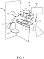
- FIG. 1 illustrates a perspective view of a lavatory 102 that includes a system 100 for disinfecting one or more components using ultraviolet (UV) light.
- the system 100 includes a plurality of UV light-emitting modules 104 configured to emit UV light.
- the UV light-emitting modules 104 can take the form of UV light-emitting module 300 shown in FIG. 3 and described in more detail below, or one of the other examples of UV light-emitting modules described herein.
- the system 100 also includes a power supply module 106 that is electrically connected to each of the UV light-emitting modules 104 and provides power to the modules to generate UV light for disinfecting and/or sanitizing components and their surfaces in the lavatory 102.
- the system 100 utilizes fewer or more than three UV light-emitting modules 104 that are electrically connected to the power supply module 106.
- the system 100 and/or individually powered UV light-emitting modules 104 can be utilized in a variety of environments, including but not limited to kitchens, galleys, retail establishments, medical facilities, arenas, places of worship, banquet halls, theatres, concert venues, commercial businesses, factories, and other spaces.
- the system 100 and/or individually powered UV light-emitting modules 104 may can be utilized in aircraft, spacecraft, and other vehicles, such as buses, trains, marine vessels, and the like.
- the system 100 can be located within a cabin, galley, crew rest area, assembly area, cargo area, flight deck, lavatory, and other areas in which individuals, passengers, flight crew, ground crew, and/or maintenance personnel may be located.
- the lavatory 102 can be located within a vehicle, such as within a cabin of a commercial aircraft.
- FIG. 27 depicts an aircraft environment in which UV light-emitting modules 104 are installed above passenger seats 1004 in the cabin 1000 of the aircraft.
- one or more UV light-emitting modules 104 may be utilized in a portable assembly, such as a wand, that is configured to be held by a user.
- a portable assembly is also configured to be removably mounted to a support structure, such as a wall.
- the UV light-emitting modules 104 are positioned to emit the UV light towards one or more components within the lavatory 102 for disinfecting and/or sanitizing the components.
- the one or more components include a sink 112 and a toilet 110.
- the UV light-emitting modules 104 are positioned to emit UV light towards different components 108.
- the first UV light-emitting module104a is positioned to emit UV light towards the toilet 110 including a flush actuator 114 (e.g., lever, button, etc.) of the toilet 110.
- the second UV light-emitting module 104b is positioned to emit UV light towards the sink 112 and the surrounding region, such as portions of the faucet 116 and countertop 118.
- the third UV light-emitting module 104c is positioned to emit UV light towards the door (not shown) used to enter and exit the lavatory 102.
- two or more UV light-emitting modules 104 are positioned to emit UV light towards a common component. In some examples, two or more UV light-emitting modules 104 are physically adjacent and/or mechanically coupled to one another.
- the power supply module 106 is electrically connected to the UV light-emitting modules 104 to provide power to the modules.
- the power supply module 106 includes processing and/or power modulation circuitry within an enclosure or housing.
- the power supply module 106 receives electrical energy from a power source, such as power distribution panel or a battery, and distributes the electrical energy among the UV light-emitting modules 104.
- the power supply module 106 is mounted within the lavatory 102 and is electrically connected to the UV light-emitting modules 104 via respective power leads 120, such as one or more electrical wires or power cables.
- respective power leads 120 such as one or more electrical wires or power cables.
- one or more of the UV light-emitting modules 104 are integrated with the power supply module 106 in a common housing.
- a UV light-emitting module 104 utilizes a small form factor to provide improved aesthetics by occupying less space.
- the smaller form factor also can enable the location of the UV light-emitting modules 104 closer to the components to be disinfected as compared to larger form factor UV light emitters.
- the smaller UV light-emitting modules 104 can be inconspicuously mounted behind or within structures that would not be possible for larger UV light emitters.
- locating the UV light-emitting modules 104 closer to components increases the radiant flux (irradiance) provided to surfaces of the components.
- a designated UV dosage can be provided to the components utilizing less energy and/or in a shorter length of time as compared to the same dosage applied by larger UV light-emitting modules.
- Figure 2 illustrates a schematic block diagram of the system 100 according to an example of the present disclosure.
- the power supply module 106 receives electrical energy from an external power source 202 that is separate and discrete from the power supply module 106.
- the power source 202 is a vehicle electrical system onboard a vehicle or an electrical system of a building or facility.
- the power source 202 is a battery, a generator, or the like.
- the power supply module 106 is electrically connected to the external power source 202 via a power conditioning circuit 204 and power cables 206 and 208.
- the power conditioning circuit 204 includes one or more rectifiers, power factor correction circuits, and/or capacitors for electromagnetic interference filtering.
- the power conditioning circuit 204 is integrated with the power supply module 106 in a common enclosure, such as a housing of the power supply module.
- the power supply module 106 receives electrical energy from the power conditioning circuit 204 and controls distribution of the electrical energy among the UV light-emitting modules 104.
- the power conditioning circuit 204 receives alternating current (AC) electrical energy from the external power source 202 and converts the AC electrical energy to DC electrical energy.
- AC alternating current
- This DC electrical energy is supplied to the power supply module 106, which converts the DC electrical energy to AC electrical energy and supplies the AC to the UV light-emitting modules 104 to power the generation of UV light as described in more detail below.
- the power supply module 106 also controls one or more operations of the UV light-emitting modules 104, such as activating and deactivating the modules, and modulating the power output of the modules.
- UV light-emitting modules of the present disclosure utilize one or more cooling features that enable the modules to operate at higher power and provide correspondingly higher UV irradiation than prior UV emitters. Additionally and in some examples described below, multiple modules are enclosed in a housing that includes one or more cooling fans to circulate air through the module(s).
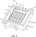
- FIGS. 3-5 one example of a UV light-emitting module 300 according to the present disclosure is illustrated.
- the UV light-emitting modules 104 described above may take the form of UV light-emitting module 300 shown in FIGS. 3-5 or one of the other examples of UV light-emitting modules described further below.
- the UV light-emitting module 300 and the other examples of UV light-emitting modules described herein can be utilized in a UV disinfecting system, such as system 100, and/or as standalone devices.
- the UV light-emitting module 300 comprises an enclosure 304 that includes a rear wall 308 and a face plate 312 spaced from the rear wall 308.
- the face plate 312 includes a light-transmitting aperture 316 through which UV light from one or more UV light emitters within the enclosure is transmitted.
- the UV light-emitting module 300 utilizes four UV light emitters 320. In other examples, fewer or more than four UV light emitters may be utilized in UV light-emitting modules according to the present disclosure.
- the UV light emitters 320 can be excimer lamps that utilize a krypton-chlorine (Kr-Cl) gas mixture provided in the lamp bulb. Such excimer lamps emit UV light having a wavelength of 222 nm that can disinfect and sanitize component surfaces via localized anti-viral and antimicrobial effects. Further, 222 nm UV light can disinfect and sanitize surfaces without skin damaging effects associated with conventional germicidal ultraviolet (UV) exposure. In other examples, the UV light-emitting module 300 can utilized other types of UV emitters and UV lamps. Additionally and as described in more detail below, the UV light emitters 320 are seated in one or more UV light emitter supports within the enclosure 304.
- Kr-Cl krypton-chlorine
- a low pass filter 324 is located adjacent to the light-transmitting aperture 316 of the face plate 312.
- the low pass filter 324 can be used to remove or filter out substantially all light emissions generated by the UV light emitters 320 except for 222 nm wavelength ultraviolet light.
- the enclosure 304 has a rectangular shape formed by a first sidewall 330, second sidewall 334, third sidewall 338 and fourth sidewall 342.
- Each of the sidewalls extends between the rear wall 308 and the face plate 312.
- other enclosures of the present disclosure can have other shapes and form factors, such as a circular enclosure formed by a single circular sidewall.
- the enclosure 304 utilizes one or more cooling features that enable the module 300 to operate at higher power and provide correspondingly higher UV irradiation than prior UV emitters.
- the enclosure includes cooling features in the form of a sidewall ventilation opening 348 in first sidewall 330 and a rear wall ventilation opening 352 in the rear wall 308. In this manner, these ventilation openings enable airflow through the interior of the enclosure 304 and over the surfaces of the UV light emitters 320, to thereby cool the emitters by transferring heat generated by emitters from the enclosure.
- ventilation openings can be provided in other locations on the enclosure 304.
- the rear wall 308 and the first sidewall 330, second sidewall 334, third sidewall 338 and fourth sidewall 342 of the enclosure 304 are fabricated from a plastic material.
- the rear wall 308 and the first sidewall 330, second sidewall 334, third sidewall 338 and fourth sidewall 342 are fabricated from aluminum.
- the aluminum walls have a higher thermal conductivity than plastic, thereby providing greater heat transfer and dissipation from the UV light emitters 320 through the walls of the enclosure 304.
- the face plate 312 is fabricated from plastic. In other examples, the face plate 312 is also fabricated from aluminum to provide even greater heat transfer from within the enclosure 304.
- the UV light emitters 320 are seated in V-shaped grooves in a first UV light emitter support 322 and a second UV light emitter support 323 that extend parallel to one another.
- the UV light emitter supports 322, 323 are also fabricated from a conductive material, such as aluminum. In this manner and by seating the UV light emitters 320 in the supports, the emitters are electrically coupled to the supports.
- the UV light emitter supports 322, 323 are fabricated from a fluoropolymer and the UV light emitters 320 are electrically coupled to a power source via lead wires.
- a thermally conductive and electrically insulating separator 350 is positioned between the UV light emitter supports and the rear wall to electrically isolate the UV light emitter supports from the aluminum rear wall.
- the thermally conductive and electrically insulating separator 350 has a thermal conductivity of approximately 15 international British thermal unit per hour per square foot per degree Fahrenheit (BTU)/(°F Hr. Ft. 2 ) or higher.
- the thermally conductive and electrically insulating separator 350 is fabricated from an alumina-based ceramic.
- the thermally conductive and electrically insulating separator 350 can be fabricated from Cotronics Durapot 810 castable ceramic cement, manufactured by Cotronics Corporation. Accordingly, in these examples the higher thermal conductivity of separator 350 further facilitates heat transfer from the enclosure to cool the UV light emitters 320.
- the first UV light emitter support 322 and second UV light emitter support 323 receive power via first electrical conductor 354 and second electrical conductor 356, respectively, that extend through the rear wall 308 into the UV light emitter supports.
- first electrical conductor 354 and second electrical conductor 356 also extend through apertures in the thermally conductive and electrically insulating separator 350.
- the first electrical conductor 354 and second electrical conductor 356 are electrically coupled to a power source via wires 360, 362.
- the power source is the power supply module 106 of system 100.
- the first electrical conductor 354 is electrically insulated from the rear wall 308 by a first electrically insulating bushing 361 between the first electrical conductor and the rear wall.
- the second electrical conductor 356 is electrically insulated from the rear wall 308 by a second electrically insulating bushing 363 between the first electrical conductor and the rear wall.
- the enclosure 304 includes attachment tabs 366 and 368 configured to receive a fastener for securing the enclosure to a surface.
- the first UV light emitter support 322 comprises a plurality of first triangular-shaped internal support surfaces 372 that are facing corresponding second triangular-shaped internal support surfaces 376 of the second UV light emitter support 323.
- each of the first triangular-shaped internal support surfaces 372 includes first radiused edges 380 along one or both upwardly extending sides and the apex.
- each of the second triangular-shaped internal support surfaces 376 includes second radiused edges 384 along one or both upwardly extending sides and the apex.
- these radiused edges can have a radius of between approximately 0.05 inches and 0.10 inches.
- a likelihood of electrical arcing between the first internal support surfaces 372 and the second internal support surfaces 376 is reduced.
- the UV light-emitting module 300 also includes a circuit board 400 comprising a UV LED that is configured to pre-ionize gas in the UV light emitters 320.
- a circuit board 400 comprising a UV LED that is configured to pre-ionize gas in the UV light emitters 320.
- the first sidewall 330 is a conductive material, such as aluminum
- an electrical insulator panel 404 is provided between the circuit board 400 and the first sidewall 330.
- one or more ventilation openings can be provided in two or more of the four sidewalls of the enclosure 304.
- the enclosure includes a first sidewall ventilation opening 348 in first sidewall 330 and a second sidewall ventilation opening 349 in third sidewall 338.
- the rear wall 308 can include two or more ventilation openings.
- the enclosure includes a first rear wall ventilation opening 352 and a second rear wall ventilation opening 353 in rear wall 308. Additionally, in this example a sidewall ventilation opening 348 in third sidewall 338 is provided.
- ventilation openings of any suitable combination, quantity, size and/or shape can be provided in one or more of the sidewalls and in the rear wall 308.
- the module 300 may include a cooling fan configured to deliver forced air through either a sidewall ventilation opening or a rear wall ventilation opening.
- a cooling fan 410 is mounted to third sidewall 338 adjacent to ducting 414 that directs air from the fan into ventilation opening 349 in third sidewall 338.
- the air passes over and through the UV light emitters 320 and other components inside the enclosure 304 and exits through rear wall ventilation opening 352 in rear wall 308.
- a fitting 420 is affixed to the rear wall ventilation opening 352 to direct the exiting airflow away from the module.
- the enclosure 304 is pneumatically sealed to contain off-gases that may be generated by the UV light emitters 320.
- the enclosure contains no ventilation openings and is pneumatically sealed to prevent any off-gasses from escaping to atmosphere.
- UV light-emitting modules of the present disclosure include one or more cooling features in the form of a heat sink feature.
- the module includes a heat sink feature in the form of a plurality of fins 428 extending from the rear wall 308.
- the fins may have different sizes and shapes, such as thin elongated plates arranged adjacent to one another.
- the number and placement of the fins on the enclosure also can vary according to applications and use environments.
- heat sink fins can additionally or alternatively be located on one or more sidewalls of the enclosure.
- modules according to the present disclosure can include one or more ventilation openings and one or more heat sink features.
- the module includes the plurality of fins 428 extending from the rear wall 308, a first rear wall ventilation opening 352 and a second rear wall ventilation opening 353 in rear wall 308, and a sidewall ventilation opening 348 in third sidewall 338.
- one or more UV light-emitting modules 300 are enclosed in a housing that provides forced ventilation via at least one cooling fan that directs air into the housing and at least one housing ventilation exit opening through which the air escapes.
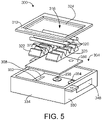
- a housing 500 includes a container portion 504 in which two UV light-emitting modules 300 according to the present disclosure are located. Both UV light-emitting modules 300 include a single sidewall ventilation opening 349 and a single rear wall ventilation opening to which a fitting 420 is affixed.
- the container portion 504 includes two intake cooling fans 510 configured to pull air into and pressurize the housing 500.
- Each of the cooling fans 510 are seated within and pneumatically coupled to a respective housing ventilation intake opening 512 in the housing 500.
- a bottom panel 514 of the container portion 504 includes module cutouts 520, 524 in which the two UV light-emitting modules 300 are seated.
- the light-transmitting apertures 316 in each of the modules 300 face downwardly through the cutouts 520, 524 to direct UV light downwardly from the housing 500.
- each of the UV light-emitting modules 300 includes a sidewall ventilation opening 349 into which pressurized air within the housing 500 enters. The air passes over and through the UV light emitters 320 and other components inside the enclosures of the modules 300 and exits through a rear wall ventilation opening 352 in rear wall 308.
- fittings 420 affixed to the rear wall ventilation openings are extend through and are pneumatically coupled to respective housing ventilation exit openings 530, 534 in cover panel 538 and direct the exiting airflow from the modules through these openings and into atmosphere.
- the two housing ventilation exit openings 530, 534 are located above the module cutouts 520, 524, respectively, in bottom panel 514 and are positioned to receive and allow the fittings 420 to extend through the openings. In this manner, the housing ventilation exit openings 530, 534 allow pressurized air within the housing 500 and UV light-emitting modules 300 to escape.
- the housing 500 can be mounted in a ceiling, wall, or other support structure, and can be utilized with stationary structures or in moveable applications, such as in a passenger or commercial vehicles, aircraft, spacecraft and the like. In some examples the housing 500 can be mounted to autonomous mobile devices such as robots.
- each of the UV light-emitting modules 300 within the housing 500 receives power from a common power source, such as the external power source 202 of the system 100 shown in FIG. 2 .
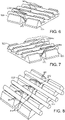
- a UV light emitter support 450 is fabricated from a fluoropolymer as a single, unitary block of material.
- the fluoropolymer is polytetrafluoroethylene (PTFE).
- the UV light emitter support 450 has a first side 454 and an opposing second side 456.
- each of the UV light emitters 320 seated in the UV light emitter support 450 is an elongated lamp having a first end 328 and an opposing second end 329.
- the first end 328 of each of the lamps extends beyond the first side 454 of the UV light emitter support 450, and the second end of each of the lamps extends beyond the second side 456 of the UV light emitter support.
- a first terminal 332 is affixed to the first end 328 of each of the elongated lamps, and a second terminal 336 is affixed to the second end 329 of each of the lamps.
- a first lead wire 340 electrically couples each of the first terminals 332 to a power source, and a second lead wire 344 electrically couples each of the second terminals 336 to the power source.
- the electrodes are moved further apart as compared to utilizing two aluminum UV light emitter supports as described in examples above. Accordingly, this configuration enables higher voltages and correspondingly higher UV outputs prior to arcing between the terminals.
- fluoropolymer materials have dielectric properties and reflect 222 nm UV light. Accordingly, this configuration also provides a larger surface area of 222 nm UV light reflective material from which UV light emitted by the UV light emitters 320 is reflected.
- fluoropolymer UV light emitter supports can be affixed directly to a conductive rear wall 308 of a UV light-emitting module 300, thereby avoiding the need for an electrically insulating separator between such supports and the rear wall.
- the fluoropolymer UV light emitter supports in these examples are dielectrics, the internal support surfaces of the supports can have angled or sharp edges, as opposed to radiused edges, without increasing the probability of arcing. Accordingly, these configurations may can simplify manufacturing and/or reduce associated production costs.
- two or more UV light emitter supports 450 fabricated from a fluoropolymer may be combined to seat the UV light emitters 320.
- three fluoropolymer UV light emitter supports 452, 455 and 457 are placed side-by-side to form a square-shaped UV light emitter support.
- the UV light emitter supports can have different lengths and widths, and can be combined to form a variety of shapes and sizes.
- UV light emitter supports fabricated from conductive materials and from fluoropolymers may be utilized.
- the UV light emitter support 455 is fabricated from a conductive material, such as aluminum, while the UV light emitter supports 452 and 457 on either side are fabricated from a fluoropolymer.
- a thermally conductive and electrically insulating separator 350 is provided between the UV light emitter supports 452, 455 and 457 and the rear wall.
- lead wires 340 and 344 electrically couple terminals of the elongated lamps to a power source.
- an electrical conductor extends through the rear wall of the UV light emitting module into each of the aluminum UV light emitter supports to provide power to the light emitters as described above.
- first ends 328 and second ends 329 of each of the UV light emitters 320 are substantially flush with the first side 454 and the second side 456, respectively, of the UV light emitter support.
- the terminals 332 and 336 at the ends of the UV light emitters 320 are substantially flush with the first side 454 and the second side 456, respectively.
- UV light-emitting modules and related systems for disinfecting one or more components of the present disclosure can utilize any suitable combinations of features described herein, including but not limited to ventilation openings, heat sink features, and component materials.
- each of the UV light-emitting modules includes an enclosure having a rear wall with a rear wall ventilation opening and a face plate spaced from the rear wall and having a light-transmitting aperture. At least one sidewall extends between the rear wall and the face plate, with the at least one sidewall having a sidewall ventilation opening.
- Each module further includes at least one UV light emitter within the enclosure.
- the housing includes at least one cooling fan configured to direct air into the housing and at least a first housing ventilation exit opening and a second housing ventilation exit opening.
- method 1300 includes the step of affixing the plurality of UV light-emitting modules inside the housing.
- the method 1300 includes the step of pneumatically coupling the first housing ventilation exit opening to the rear wall ventilation opening of a first UV light-emitting module of the plurality of UV light-emitting modules.
- the method 1300 includes pneumatically coupling the second housing ventilation exit opening to the rear wall ventilation opening of a second UV light-emitting module of the plurality of UV light-emitting modules.
- FIG. 25 a method 1400 of assembling an ultraviolet (UV) light-emitting module for disinfecting one or more components is illustrated.
- the method 1400 is performed using an enclosure including a rear wall and a face plate spaced from the rear wall that includes a light-transmitting aperture.
- the enclosure also includes four sidewall that extend between the rear wall and the face plate.
- the method 1400 is also performed using a first UV light emitter support and a second UV light emitter support, and at least one cooling feature selected from (1) a sidewall ventilation opening in the at least one sidewall and (2) a heat sink feature extending from the rear wall.
- the method 1400 includes the step of inserting a first electrical conductor through the rear wall and through a thermally conductive and electrically insulating separator into the first UV light emitter support.
- the method 1400 includes the step of inserting a second electrical conductor through the rear wall and through the thermally conductive and electrically insulating separator into the second UV light emitter support.
- the method 1400 includes the step of securing a plurality of UV light emitters to the first aluminum UV light emitter support and the second aluminum UV light emitter support within the enclosure.
- FIG. 26 a method 1500 of assembling an ultraviolet (UV) light-emitting module for disinfecting one or more components is illustrated.
- the method 1500 is performed using an enclosure that includes a rear wall and a face plate spaced from the rear wall and having a light-transmitting aperture, and four sidewalls extending between the rear wall and the face plate, at least one UV light emitter support fabricated from a fluoropolymer, at least one cooling feature selected from (1) a sidewall ventilation opening in the at least one sidewall and (2) a heat sink feature extending from the rear wall, and at least one UV light emitter comprising an elongated lamp that comprises a first end having a first terminal and an opposing second end having a second terminal.
- UV ultraviolet
- the method 1500 includes the step of seating the elongated lamp in the at least one fluoropolymer UV light emitter support within the enclosure.
- the method 1500 includes the step of securing a first lead wire to the first terminal of the elongated lamp.
- the method 1400 includes the step of securing a second lead wire to the second terminal of the elongated lamp.
- An ultraviolet (UV) light-emitting module for disinfecting one or more components, the module comprising an enclosure comprising a rectangular aluminum rear wall comprising a rear wall ventilation opening; a rectangular face plate spaced from the rear wall and comprising a light-transmitting aperture; and four aluminum sidewalls extending between the rear wall and the face plate, wherein at least one sidewall of the four aluminum sidewalls comprises a sidewall ventilation opening; a plurality of UV light emitters within the enclosure; at least one aluminum UV light emitter support within the enclosure that is electrically coupled to the plurality of UV light emitters; a thermally conductive and electrically insulating separator between the at least one aluminum UV light emitter support and the rear wall; at least one electrical conductor extending through the rear wall and the thermally conductive and electrically insulating separator into the at least one aluminum UV light emitter support; and an electrically insulating bushing extending between the at least one electrical conductor and surfaces of the aluminum rear wall.
- UV ultraviolet
- the at least one aluminum UV light emitter support comprises a first aluminum UV light emitter support and a second aluminum UV light emitter support extending parallel to the first aluminum UV light emitter support, the first aluminum UV light emitter support comprising a plurality of first internal support surfaces, the second aluminum UV light emitter support comprising a plurality of second internal support surfaces that each face a corresponding first internal support surface of the first aluminum UV light emitter support, wherein each of the first internal support surfaces and the second internal support surfaces comprise radiused edges that reduce a likelihood of electrical arcing between the first internal support surfaces and the second internal support surfaces.
- each of the plurality of UV light emitters comprises an elongated lamp having a first end and an opposing second end, wherein the first end extends beyond the first side and the second end extends beyond the second side.
- each of the plurality of UV light emitters comprises an elongated lamp having a first end and an opposing second end, wherein the first end is substantially flush with the first side and the second end is substantially flush with the second side.
- Clause 13 The UV light-emitting module of any of clauses 1-12, wherein the plurality of UV light emitters are configured to emit 222 nm wavelength UV light.
- Clause 14 The UV light-emitting module of any of clauses 1-13, further comprising a low pass filter adjacent to the light-transmitting aperture of the face plate.
- each of the plurality of UV light emitters comprises an excimer lamp, the module further comprising a circuit board comprising a UV LED configured to pre-ionize gas in the excimer lamp.
- a system for disinfecting one or more components comprising: a plurality of ultraviolet (UV) light-emitting modules, wherein each of the UV light-emitting modules comprises: an enclosure comprising: a rectangular aluminum rear wall comprising a rear wall ventilation opening; a rectangular face plate spaced from the rear wall and comprising a light-transmitting aperture; and four aluminum sidewalls extending between the rear wall and the face plate, wherein at least one sidewall of the four aluminum sidewalls comprises a sidewall ventilation opening; a plurality of UV light emitters within the enclosure; at least one aluminum UV light emitter support within the enclosure that is electrically coupled to the plurality of UV light emitters; a thermally conductive and electrically insulating separator between the at least one aluminum UV light emitter support and the rear wall; at least one electrical conductor extending through the rear wall and the thermally conductive and electrically insulating separator into the at least one aluminum UV light emitter support; and an electrically insulating bushing extending between the at least one electrical
- each of the UV light-emitting modules receives power from a common power source.
- Clause 18 The system of any of clauses 16-17, wherein the housing comprises a plurality of housing ventilation exit openings through which air escapes, wherein each of the housing ventilation exit openings is pneumatically coupled to one of the rear wall ventilation openings in one of the UV light-emitting modules.
- Clause 19 The system of clause 18, wherein the at least one cooling fan is pneumatically coupled to a housing ventilation intake opening in the housing.
- a method of assembling a system for disinfecting one or more components the method performed using plurality of ultraviolet (UV) light-emitting modules and a housing, wherein each of the UV light-emitting modules includes an enclosure having a rear wall with a rear wall ventilation opening, a face plate spaced from the rear wall and having a light-transmitting aperture, and at least one sidewall extending between the rear wall and the face plate, the at least one sidewall having a sidewall ventilation opening, each module further includes at least one UV light emitter within the enclosure, and wherein the housing includes at least one cooling fan configured to direct air into the housing and at least a first housing ventilation exit opening and a second housing ventilation exit opening, the method comprising: affixing the plurality of UV light-emitting modules inside the housing; pneumatically coupling the first housing ventilation exit opening to the rear wall ventilation opening of a first UV light-emitting module of the plurality of UV light-emitting modules; and pneumatically coupling the second housing ventilation exit opening to the rear wall
- the subject disclosure includes all novel and non-obvious combinations and subcombinations of the various features and techniques disclosed herein.
- the various features and techniques disclosed herein are not necessarily required of all examples of the subject disclosure.
- the various features and techniques disclosed herein may define patentable subject matter apart from the disclosed examples and may find utility in other implementations not expressly disclosed herein.
Landscapes
- Health & Medical Sciences (AREA)
- Animal Behavior & Ethology (AREA)
- Epidemiology (AREA)
- Life Sciences & Earth Sciences (AREA)
- General Health & Medical Sciences (AREA)
- Public Health (AREA)
- Veterinary Medicine (AREA)
- Physics & Mathematics (AREA)
- Optics & Photonics (AREA)
- General Physics & Mathematics (AREA)
- Toxicology (AREA)
- Apparatus For Disinfection Or Sterilisation (AREA)
- Led Device Packages (AREA)
Applications Claiming Priority (3)
| Application Number | Priority Date | Filing Date | Title |
|---|---|---|---|
| US202063124341P | 2020-12-11 | 2020-12-11 | |
| US202163154239P | 2021-02-26 | 2021-02-26 | |
| US17/452,560 US12023413B2 (en) | 2020-12-11 | 2021-10-27 | Ultraviolet light-emitting module and disinfecting system |
Publications (3)
| Publication Number | Publication Date |
|---|---|
| EP4011402A2 true EP4011402A2 (de) | 2022-06-15 |
| EP4011402A3 EP4011402A3 (de) | 2022-10-05 |
| EP4011402B1 EP4011402B1 (de) | 2024-08-07 |
Family
ID=78806328
Family Applications (1)
| Application Number | Title | Priority Date | Filing Date |
|---|---|---|---|
| EP21210725.4A Active EP4011402B1 (de) | 2020-12-11 | 2021-11-26 | Ultraviolettes licht-emittierendes modul und desinfektionssystem |
Country Status (4)
| Country | Link |
|---|---|
| US (1) | US12023413B2 (de) |
| EP (1) | EP4011402B1 (de) |
| JP (1) | JP7754695B2 (de) |
| CN (1) | CN114617989A (de) |
Families Citing this family (4)
| Publication number | Priority date | Publication date | Assignee | Title |
|---|---|---|---|---|
| US11730844B1 (en) | 2020-12-18 | 2023-08-22 | Zoox, Inc. | Method of disinfecting vehicle using UVC light emitters |
| US11931472B1 (en) * | 2020-12-18 | 2024-03-19 | Zoox, Inc. | Vehicle with UVC light emitters |
| JP2022167486A (ja) * | 2021-04-23 | 2022-11-04 | トヨタ自動車株式会社 | 車両運用システム及び自動運転車両 |
| US12106955B2 (en) * | 2021-10-20 | 2024-10-01 | Goodrich Corporation | Excimer lamp electrode geometry |
Family Cites Families (69)
| Publication number | Priority date | Publication date | Assignee | Title |
|---|---|---|---|---|
| US5216251A (en) | 1991-10-18 | 1993-06-01 | Matschke Arthur L | Apparatus and method for a bio-conditioning germicidal dryer |
| JP3646820B2 (ja) | 1996-01-30 | 2005-05-11 | 岩崎電気株式会社 | 紫外線殺菌装置 |
| US6144175A (en) | 1997-11-05 | 2000-11-07 | Parra; Jorge M. | Low-voltage ballast-free energy-efficient ultraviolet material treatment and purification system and method |
| JP2000283840A (ja) | 1999-03-31 | 2000-10-13 | Minolta Co Ltd | 測光機器 |
| US6656424B1 (en) | 2000-02-18 | 2003-12-02 | Uvas, Llc | Ultraviolet area sterilizer and method of area sterilization using ultraviolet radiation |
| US6880351B2 (en) | 2001-09-05 | 2005-04-19 | Be Intellectual Property, Inc. | Liquid galley refrigeration system for aircraft |
| ITFI20010172A1 (it) | 2001-09-17 | 2003-03-17 | El En Spa | Apparecchiatura con lampada a spettro nell'ultravioletto,per il trattamento della psoriasi |
| US7875247B2 (en) | 2002-11-27 | 2011-01-25 | Novatron, Inc. | UV flux multiplication system for sterilizing air, medical devices and other materials |
| US7595723B2 (en) | 2005-11-14 | 2009-09-29 | Edwards Lifesciences Corporation | Wireless communication protocol for a medical sensor system |
| US8941078B2 (en) | 2006-03-29 | 2015-01-27 | Jansyl Industries, Llc | Infant stimulation and environment sterilizing device |
| GB2451873B (en) | 2007-08-15 | 2009-08-12 | Jenact Ltd | UV irradiator |
| US8581522B2 (en) | 2008-09-19 | 2013-11-12 | Mathew Inskeep | Countertop decontaminating device |
| GB2470415A (en) | 2009-05-22 | 2010-11-24 | Steritrox Ltd | A sterilisation and decontamination device |
| US8662705B2 (en) | 2010-03-30 | 2014-03-04 | Virwall Systems, Inc. | Flexible ultraviolet LED sanitizing apparatus |
| US20120168641A1 (en) | 2010-09-08 | 2012-07-05 | Lizotte Todd E | Uv ptfe diffuser technology |
| US8698100B2 (en) | 2011-03-23 | 2014-04-15 | Dean Schumacher | System and apparatus for sanitizing a door opening device or other point of contact |
| BR112013026529A2 (pt) | 2011-04-15 | 2016-09-20 | Samuel Richard Trapani | método e sistema de esterilização de ambiente |
| US20120305787A1 (en) | 2011-06-04 | 2012-12-06 | Brian Roy Henson | Apparatus and Method for Area Disinfection Using Ultraviolet Light |
| US9919068B2 (en) | 2012-08-28 | 2018-03-20 | Sensor Electronic Technology, Inc. | Storage device including ultraviolet illumination |
| JP2016500284A (ja) | 2012-12-06 | 2016-01-12 | ゼネックス・ディスインフェクション・サービシィズ・エルエルシイ | 殺菌デバイスの動作パラメータ及び消毒スケジュールを決定するシステム、並びにレンズシステムを含む殺菌ランプ装置 |
| US8907304B2 (en) | 2013-02-27 | 2014-12-09 | Arthur Kreitenberg | Ultraviolet autonomous trolley for sanitizing aircraft |
| US8791441B1 (en) | 2013-08-27 | 2014-07-29 | George Jay Lichtblau | Ultraviolet radiation system |
| WO2015028334A1 (en) | 2013-08-29 | 2015-03-05 | Koninklijke Philips N.V. | A light emitting device and a method for manufacturing a light emitting device |
| DE112014004109B4 (de) * | 2013-09-06 | 2021-05-20 | Sensor Electronic Technology Inc. | Diffuse Ultraviolettbeleuchtung |
| KR20150045628A (ko) | 2013-10-21 | 2015-04-29 | 서울바이오시스 주식회사 | 살충 및 살균 기능을 포함하는 좌석 시스템 |
| DE102014101935B4 (de) | 2014-02-17 | 2018-05-30 | Heraeus Noblelight Gmbh | Betriebsverfahren für eine Bestrahlungsvorrichtung |
| WO2016079658A1 (en) * | 2014-11-18 | 2016-05-26 | Industries Yifei Wang Inc. | Led module, methods of manufacturing same and luminaire integrating same |
| US9623133B2 (en) | 2015-01-30 | 2017-04-18 | The Boeing Company | Lavatory disinfection system |
| US9457121B1 (en) * | 2015-03-17 | 2016-10-04 | Matthew Phillip Davis | Ultraviolate light sterilization apparatus |
| US9987383B2 (en) | 2015-05-07 | 2018-06-05 | Sensor Electronic Technology, Inc. | Medical device treatment |
| WO2016210399A2 (en) | 2015-06-25 | 2016-12-29 | Daylight Medical, Inc. | Decontamination system and decontamination unit housing equipped with remote control |
| CN113069570B (zh) | 2015-06-26 | 2023-07-14 | 首尔伟傲世有限公司 | 便携式杀菌装置 |
| JP6256813B2 (ja) | 2015-08-18 | 2018-01-10 | ウシオ電機株式会社 | 光線治療器 |
| RU2719338C2 (ru) | 2016-01-07 | 2020-04-17 | Майкл МЕЙ | Модульные соединители для осветительного устройства в сборе |
| CN106049005B (zh) | 2016-07-19 | 2018-12-04 | 湖南城市学院 | 一种杀菌带红外遥控的袜子速干机 |
| US10918748B2 (en) | 2016-09-08 | 2021-02-16 | The Boeing Company | Deployable ultraviolet light sanitizing systems and methods |
| JP6800678B2 (ja) | 2016-09-29 | 2020-12-16 | 株式会社オーク製作所 | 放電ランプおよび放電ランプ装置 |
| JP6862803B2 (ja) | 2016-12-01 | 2021-04-21 | 岩崎電気株式会社 | 照射装置 |
| US10910210B2 (en) | 2017-01-10 | 2021-02-02 | Ushio Denki Kabushiki Kaisha | Ultraviolet sterilizer |
| WO2018170604A1 (en) * | 2017-03-23 | 2018-09-27 | Barry Hunt | Systems and apparratus for ultraviolet light disinfection |
| JP2018167166A (ja) | 2017-03-29 | 2018-11-01 | ウシオ電機株式会社 | 光照射装置、及びこれを備えた光硬化装置 |
| US10994040B2 (en) | 2017-05-26 | 2021-05-04 | Sensor Electronic Technology, Inc. | Surface treatment with ultraviolet light |
| JP7314138B2 (ja) | 2017-12-11 | 2023-07-25 | ダブリュ.エル.ゴア アンド アソシエイツ,インコーポレイティド | 可撓性紫外光生成シート及びシステムを製造するための方法 |
| US10427792B1 (en) | 2018-04-01 | 2019-10-01 | The Boeing Company | Vehicle with a simulated window feature |
| WO2020040990A1 (en) | 2018-08-21 | 2020-02-27 | Gentex Corporation | Disinfection system |
| CN209060072U (zh) | 2018-09-10 | 2019-07-05 | 深圳市开颜医疗器械有限公司 | 一种消毒照明系统 |
| US12194168B2 (en) | 2018-12-19 | 2025-01-14 | Vyv, Inc. | Lighting and dissipation device |
| CN111744026B (zh) | 2019-03-29 | 2023-08-18 | 东芝照明技术株式会社 | 紫外线放射装置以及照明装置 |
| TWI841791B (zh) * | 2019-10-07 | 2024-05-11 | 日商牛尾電機股份有限公司 | 紫外線照射裝置 |
| CN211204004U (zh) | 2019-11-21 | 2020-08-07 | 深圳市隆兴达科技有限公司 | 一种照明抑菌一体化灯具 |
| US20210361794A1 (en) | 2020-02-24 | 2021-11-25 | Stephen A. Yencho | Portable Infection Prevention Systems |
| US12576172B2 (en) | 2020-05-08 | 2026-03-17 | The Boeing Company | Ultraviolet light sanitizing cart having a wand assembly |
| US11957810B2 (en) | 2020-05-08 | 2024-04-16 | The Boeing Company | Ultraviolet light sanitizing pacing systems and methods |
| US20210386883A1 (en) | 2020-06-11 | 2021-12-16 | The Boeing Company | Ultraviolet sanitizing pacing systems and methods |
| US20210346540A1 (en) | 2020-05-08 | 2021-11-11 | The Boeing Company | Portable sanitizing system having a backpack assembly coupled to a wand assembly |
| US11382993B2 (en) | 2020-05-20 | 2022-07-12 | The Boeing Company | Portable sanitizing systems and methods with range guidance |
| US11679169B2 (en) | 2020-06-11 | 2023-06-20 | The Boeing Company | Systems and methods for providing power to ultraviolet lamps of sanitizing systems |
| US11617810B2 (en) | 2020-06-11 | 2023-04-04 | The Boeing Company | Systems and methods for providing power to ultraviolet lamps of sanitizing systems |
| US11782197B2 (en) | 2020-06-23 | 2023-10-10 | The Boeing Company | Ultraviolet light wavelength selective filter |
| US11793896B2 (en) | 2020-07-22 | 2023-10-24 | The Boeing Company | Portable sanitizing systems and methods |
| US20220023459A1 (en) | 2020-07-23 | 2022-01-27 | The Boeing Company | Ultraviolet light sanitizing cart |
| US12233178B2 (en) | 2020-07-23 | 2025-02-25 | The Boeing Company | Systems and methods of verifying effective motion of a wand assembly of an ultraviolet (UV) light sanitizing system |
| JP6947261B1 (ja) | 2020-09-01 | 2021-10-13 | ウシオ電機株式会社 | 紫外線照射装置 |
| US11933477B2 (en) | 2020-10-14 | 2024-03-19 | The Boeing Company | Systems and methods for aligning ultraviolet lamps |
| US20220111087A1 (en) | 2020-10-14 | 2022-04-14 | The Boeing Company | Ultraviolet light sanitizing systems and methods |
| US12076452B2 (en) | 2020-10-14 | 2024-09-03 | The Boeing Company | Modulated ultraviolet light sanitizing system and method |
| US20220111096A1 (en) | 2020-10-14 | 2022-04-14 | The Boeing Company | Ultraviolet light sanitizing systems and methods |
| US20220133925A1 (en) | 2020-11-03 | 2022-05-05 | Wholetek Inc. | Sanitizing apparatus |
| EP4011400B1 (de) | 2020-12-11 | 2025-07-23 | The Boeing Company | System und verfahren zur desinfektion mit ultraviolettem licht mit verteilter energie |
-
2021
- 2021-10-27 US US17/452,560 patent/US12023413B2/en active Active
- 2021-11-25 JP JP2021191191A patent/JP7754695B2/ja active Active
- 2021-11-26 EP EP21210725.4A patent/EP4011402B1/de active Active
- 2021-12-10 CN CN202111508512.5A patent/CN114617989A/zh active Pending
Also Published As
| Publication number | Publication date |
|---|---|
| JP2022093286A (ja) | 2022-06-23 |
| EP4011402A3 (de) | 2022-10-05 |
| EP4011402B1 (de) | 2024-08-07 |
| US20220184249A1 (en) | 2022-06-16 |
| US12023413B2 (en) | 2024-07-02 |
| JP7754695B2 (ja) | 2025-10-15 |
| CN114617989A (zh) | 2022-06-14 |
Similar Documents
| Publication | Publication Date | Title |
|---|---|---|
| US12023413B2 (en) | Ultraviolet light-emitting module and disinfecting system | |
| US12377180B2 (en) | Ultraviolet light-emitting module and disinfecting system | |
| US12246103B2 (en) | Ultraviolet light sanitizing system and method with distributed power | |
| US12053554B2 (en) | Ultraviolet light-emitting module and disinfecting system | |
| EP3923681B1 (de) | Systeme und verfahren zur stromversorgung von uv-lampen von desinfektionssystemen | |
| US12165864B2 (en) | Ultraviolet light-emitting module and disinfecting system | |
| US20250339574A1 (en) | Ultraviolet light-emitting assembly | |
| US12582739B2 (en) | UVC air disinfection device with LED thermal management system | |
| JP2010097915A (ja) | 非常用照明装置 | |
| US20230059472A1 (en) | Air cleaning apparatus and methods of providing and using the same | |
| KR20140002728U (ko) | 방송 및 공연용 led 조명기구 | |
| US20240033393A1 (en) | Far-uvc emitter |
Legal Events
| Date | Code | Title | Description |
|---|---|---|---|
| PUAI | Public reference made under article 153(3) epc to a published international application that has entered the european phase |
Free format text: ORIGINAL CODE: 0009012 |
|
| STAA | Information on the status of an ep patent application or granted ep patent |
Free format text: STATUS: THE APPLICATION HAS BEEN PUBLISHED |
|
| AK | Designated contracting states |
Kind code of ref document: A2 Designated state(s): AL AT BE BG CH CY CZ DE DK EE ES FI FR GB GR HR HU IE IS IT LI LT LU LV MC MK MT NL NO PL PT RO RS SE SI SK SM TR |
|
| PUAL | Search report despatched |
Free format text: ORIGINAL CODE: 0009013 |
|
| AK | Designated contracting states |
Kind code of ref document: A3 Designated state(s): AL AT BE BG CH CY CZ DE DK EE ES FI FR GB GR HR HU IE IS IT LI LT LU LV MC MK MT NL NO PL PT RO RS SE SI SK SM TR |
|
| RIC1 | Information provided on ipc code assigned before grant |
Ipc: H01J 65/04 20060101ALI20220831BHEP Ipc: H01J 61/54 20060101ALI20220831BHEP Ipc: G02B 5/20 20060101ALI20220831BHEP Ipc: F21V 29/00 20150101ALI20220831BHEP Ipc: F21K 9/00 20160101ALI20220831BHEP Ipc: F24F 8/22 20210101ALI20220831BHEP Ipc: F21V 7/00 20060101ALI20220831BHEP Ipc: E03D 9/00 20060101ALI20220831BHEP Ipc: B64C 39/00 20060101ALI20220831BHEP Ipc: B08B 7/00 20060101ALI20220831BHEP Ipc: A61L 9/20 20060101ALI20220831BHEP Ipc: A61L 2/10 20060101AFI20220831BHEP |
|
| RAP3 | Party data changed (applicant data changed or rights of an application transferred) |
Owner name: THE BOEING COMPANY |
|
| STAA | Information on the status of an ep patent application or granted ep patent |
Free format text: STATUS: REQUEST FOR EXAMINATION WAS MADE |
|
| 17P | Request for examination filed |
Effective date: 20230405 |
|
| RBV | Designated contracting states (corrected) |
Designated state(s): AL AT BE BG CH CY CZ DE DK EE ES FI FR GB GR HR HU IE IS IT LI LT LU LV MC MK MT NL NO PL PT RO RS SE SI SK SM TR |
|
| STAA | Information on the status of an ep patent application or granted ep patent |
Free format text: STATUS: EXAMINATION IS IN PROGRESS |
|
| 17Q | First examination report despatched |
Effective date: 20230925 |
|
| GRAP | Despatch of communication of intention to grant a patent |
Free format text: ORIGINAL CODE: EPIDOSNIGR1 |
|
| STAA | Information on the status of an ep patent application or granted ep patent |
Free format text: STATUS: GRANT OF PATENT IS INTENDED |
|
| INTG | Intention to grant announced |
Effective date: 20240319 |
|
| GRAS | Grant fee paid |
Free format text: ORIGINAL CODE: EPIDOSNIGR3 |
|
| GRAA | (expected) grant |
Free format text: ORIGINAL CODE: 0009210 |
|
| STAA | Information on the status of an ep patent application or granted ep patent |
Free format text: STATUS: THE PATENT HAS BEEN GRANTED |
|
| AK | Designated contracting states |
Kind code of ref document: B1 Designated state(s): AL AT BE BG CH CY CZ DE DK EE ES FI FR GB GR HR HU IE IS IT LI LT LU LV MC MK MT NL NO PL PT RO RS SE SI SK SM TR |
|
| P01 | Opt-out of the competence of the unified patent court (upc) registered |
Free format text: CASE NUMBER: APP_39494/2024 Effective date: 20240702 |
|
| REG | Reference to a national code |
Ref country code: GB Ref legal event code: FG4D |
|
| REG | Reference to a national code |
Ref country code: CH Ref legal event code: EP |
|
| REG | Reference to a national code |
Ref country code: IE Ref legal event code: FG4D |
|
| REG | Reference to a national code |
Ref country code: DE Ref legal event code: R096 Ref document number: 602021016760 Country of ref document: DE |
|
| REG | Reference to a national code |
Ref country code: LT Ref legal event code: MG9D |
|
| REG | Reference to a national code |
Ref country code: NL Ref legal event code: MP Effective date: 20240807 |
|
| PG25 | Lapsed in a contracting state [announced via postgrant information from national office to epo] |
Ref country code: NO Free format text: LAPSE BECAUSE OF FAILURE TO SUBMIT A TRANSLATION OF THE DESCRIPTION OR TO PAY THE FEE WITHIN THE PRESCRIBED TIME-LIMIT Effective date: 20241107 |
|
| REG | Reference to a national code |
Ref country code: AT Ref legal event code: MK05 Ref document number: 1710207 Country of ref document: AT Kind code of ref document: T Effective date: 20240807 |
|
| PG25 | Lapsed in a contracting state [announced via postgrant information from national office to epo] |
Ref country code: GR Free format text: LAPSE BECAUSE OF FAILURE TO SUBMIT A TRANSLATION OF THE DESCRIPTION OR TO PAY THE FEE WITHIN THE PRESCRIBED TIME-LIMIT Effective date: 20241108 Ref country code: NL Free format text: LAPSE BECAUSE OF FAILURE TO SUBMIT A TRANSLATION OF THE DESCRIPTION OR TO PAY THE FEE WITHIN THE PRESCRIBED TIME-LIMIT Effective date: 20240807 Ref country code: PT Free format text: LAPSE BECAUSE OF FAILURE TO SUBMIT A TRANSLATION OF THE DESCRIPTION OR TO PAY THE FEE WITHIN THE PRESCRIBED TIME-LIMIT Effective date: 20241209 Ref country code: PL Free format text: LAPSE BECAUSE OF FAILURE TO SUBMIT A TRANSLATION OF THE DESCRIPTION OR TO PAY THE FEE WITHIN THE PRESCRIBED TIME-LIMIT Effective date: 20240807 Ref country code: FI Free format text: LAPSE BECAUSE OF FAILURE TO SUBMIT A TRANSLATION OF THE DESCRIPTION OR TO PAY THE FEE WITHIN THE PRESCRIBED TIME-LIMIT Effective date: 20240807 |
|
| PG25 | Lapsed in a contracting state [announced via postgrant information from national office to epo] |
Ref country code: BG Free format text: LAPSE BECAUSE OF FAILURE TO SUBMIT A TRANSLATION OF THE DESCRIPTION OR TO PAY THE FEE WITHIN THE PRESCRIBED TIME-LIMIT Effective date: 20240807 |
|
| PG25 | Lapsed in a contracting state [announced via postgrant information from national office to epo] |
Ref country code: LV Free format text: LAPSE BECAUSE OF FAILURE TO SUBMIT A TRANSLATION OF THE DESCRIPTION OR TO PAY THE FEE WITHIN THE PRESCRIBED TIME-LIMIT Effective date: 20240807 |
|
| PG25 | Lapsed in a contracting state [announced via postgrant information from national office to epo] |
Ref country code: IS Free format text: LAPSE BECAUSE OF FAILURE TO SUBMIT A TRANSLATION OF THE DESCRIPTION OR TO PAY THE FEE WITHIN THE PRESCRIBED TIME-LIMIT Effective date: 20241207 Ref country code: AT Free format text: LAPSE BECAUSE OF FAILURE TO SUBMIT A TRANSLATION OF THE DESCRIPTION OR TO PAY THE FEE WITHIN THE PRESCRIBED TIME-LIMIT Effective date: 20240807 |
|
| PG25 | Lapsed in a contracting state [announced via postgrant information from national office to epo] |
Ref country code: HR Free format text: LAPSE BECAUSE OF FAILURE TO SUBMIT A TRANSLATION OF THE DESCRIPTION OR TO PAY THE FEE WITHIN THE PRESCRIBED TIME-LIMIT Effective date: 20240807 |
|
| PG25 | Lapsed in a contracting state [announced via postgrant information from national office to epo] |
Ref country code: RS Free format text: LAPSE BECAUSE OF FAILURE TO SUBMIT A TRANSLATION OF THE DESCRIPTION OR TO PAY THE FEE WITHIN THE PRESCRIBED TIME-LIMIT Effective date: 20241107 Ref country code: ES Free format text: LAPSE BECAUSE OF FAILURE TO SUBMIT A TRANSLATION OF THE DESCRIPTION OR TO PAY THE FEE WITHIN THE PRESCRIBED TIME-LIMIT Effective date: 20240807 |
|
| PG25 | Lapsed in a contracting state [announced via postgrant information from national office to epo] |
Ref country code: RS Free format text: LAPSE BECAUSE OF FAILURE TO SUBMIT A TRANSLATION OF THE DESCRIPTION OR TO PAY THE FEE WITHIN THE PRESCRIBED TIME-LIMIT Effective date: 20241107 Ref country code: PT Free format text: LAPSE BECAUSE OF FAILURE TO SUBMIT A TRANSLATION OF THE DESCRIPTION OR TO PAY THE FEE WITHIN THE PRESCRIBED TIME-LIMIT Effective date: 20241209 Ref country code: PL Free format text: LAPSE BECAUSE OF FAILURE TO SUBMIT A TRANSLATION OF THE DESCRIPTION OR TO PAY THE FEE WITHIN THE PRESCRIBED TIME-LIMIT Effective date: 20240807 Ref country code: NO Free format text: LAPSE BECAUSE OF FAILURE TO SUBMIT A TRANSLATION OF THE DESCRIPTION OR TO PAY THE FEE WITHIN THE PRESCRIBED TIME-LIMIT Effective date: 20241107 Ref country code: NL Free format text: LAPSE BECAUSE OF FAILURE TO SUBMIT A TRANSLATION OF THE DESCRIPTION OR TO PAY THE FEE WITHIN THE PRESCRIBED TIME-LIMIT Effective date: 20240807 Ref country code: LV Free format text: LAPSE BECAUSE OF FAILURE TO SUBMIT A TRANSLATION OF THE DESCRIPTION OR TO PAY THE FEE WITHIN THE PRESCRIBED TIME-LIMIT Effective date: 20240807 Ref country code: IS Free format text: LAPSE BECAUSE OF FAILURE TO SUBMIT A TRANSLATION OF THE DESCRIPTION OR TO PAY THE FEE WITHIN THE PRESCRIBED TIME-LIMIT Effective date: 20241207 Ref country code: HR Free format text: LAPSE BECAUSE OF FAILURE TO SUBMIT A TRANSLATION OF THE DESCRIPTION OR TO PAY THE FEE WITHIN THE PRESCRIBED TIME-LIMIT Effective date: 20240807 Ref country code: GR Free format text: LAPSE BECAUSE OF FAILURE TO SUBMIT A TRANSLATION OF THE DESCRIPTION OR TO PAY THE FEE WITHIN THE PRESCRIBED TIME-LIMIT Effective date: 20241108 Ref country code: FI Free format text: LAPSE BECAUSE OF FAILURE TO SUBMIT A TRANSLATION OF THE DESCRIPTION OR TO PAY THE FEE WITHIN THE PRESCRIBED TIME-LIMIT Effective date: 20240807 Ref country code: ES Free format text: LAPSE BECAUSE OF FAILURE TO SUBMIT A TRANSLATION OF THE DESCRIPTION OR TO PAY THE FEE WITHIN THE PRESCRIBED TIME-LIMIT Effective date: 20240807 Ref country code: BG Free format text: LAPSE BECAUSE OF FAILURE TO SUBMIT A TRANSLATION OF THE DESCRIPTION OR TO PAY THE FEE WITHIN THE PRESCRIBED TIME-LIMIT Effective date: 20240807 Ref country code: AT Free format text: LAPSE BECAUSE OF FAILURE TO SUBMIT A TRANSLATION OF THE DESCRIPTION OR TO PAY THE FEE WITHIN THE PRESCRIBED TIME-LIMIT Effective date: 20240807 |
|
| PG25 | Lapsed in a contracting state [announced via postgrant information from national office to epo] |
Ref country code: SM Free format text: LAPSE BECAUSE OF FAILURE TO SUBMIT A TRANSLATION OF THE DESCRIPTION OR TO PAY THE FEE WITHIN THE PRESCRIBED TIME-LIMIT Effective date: 20240807 Ref country code: DK Free format text: LAPSE BECAUSE OF FAILURE TO SUBMIT A TRANSLATION OF THE DESCRIPTION OR TO PAY THE FEE WITHIN THE PRESCRIBED TIME-LIMIT Effective date: 20240807 |
|
| PG25 | Lapsed in a contracting state [announced via postgrant information from national office to epo] |
Ref country code: EE Free format text: LAPSE BECAUSE OF FAILURE TO SUBMIT A TRANSLATION OF THE DESCRIPTION OR TO PAY THE FEE WITHIN THE PRESCRIBED TIME-LIMIT Effective date: 20240807 |
|
| PG25 | Lapsed in a contracting state [announced via postgrant information from national office to epo] |
Ref country code: CZ Free format text: LAPSE BECAUSE OF FAILURE TO SUBMIT A TRANSLATION OF THE DESCRIPTION OR TO PAY THE FEE WITHIN THE PRESCRIBED TIME-LIMIT Effective date: 20240807 |
|
| PG25 | Lapsed in a contracting state [announced via postgrant information from national office to epo] |
Ref country code: SK Free format text: LAPSE BECAUSE OF FAILURE TO SUBMIT A TRANSLATION OF THE DESCRIPTION OR TO PAY THE FEE WITHIN THE PRESCRIBED TIME-LIMIT Effective date: 20240807 |
|
| REG | Reference to a national code |
Ref country code: DE Ref legal event code: R097 Ref document number: 602021016760 Country of ref document: DE |
|
| PLBE | No opposition filed within time limit |
Free format text: ORIGINAL CODE: 0009261 |
|
| STAA | Information on the status of an ep patent application or granted ep patent |
Free format text: STATUS: NO OPPOSITION FILED WITHIN TIME LIMIT |
|
| REG | Reference to a national code |
Ref country code: CH Ref legal event code: PL |
|
| PG25 | Lapsed in a contracting state [announced via postgrant information from national office to epo] |
Ref country code: MC Free format text: LAPSE BECAUSE OF FAILURE TO SUBMIT A TRANSLATION OF THE DESCRIPTION OR TO PAY THE FEE WITHIN THE PRESCRIBED TIME-LIMIT Effective date: 20240807 |
|
| PG25 | Lapsed in a contracting state [announced via postgrant information from national office to epo] |
Ref country code: LU Free format text: LAPSE BECAUSE OF NON-PAYMENT OF DUE FEES Effective date: 20241126 |
|
| REG | Reference to a national code |
Ref country code: CH Ref legal event code: PL |
|
| 26N | No opposition filed |
Effective date: 20250508 |
|
| PG25 | Lapsed in a contracting state [announced via postgrant information from national office to epo] |
Ref country code: CH Free format text: LAPSE BECAUSE OF NON-PAYMENT OF DUE FEES Effective date: 20241130 |
|
| REG | Reference to a national code |
Ref country code: BE Ref legal event code: MM Effective date: 20241130 |
|
| PG25 | Lapsed in a contracting state [announced via postgrant information from national office to epo] |
Ref country code: SE Free format text: LAPSE BECAUSE OF FAILURE TO SUBMIT A TRANSLATION OF THE DESCRIPTION OR TO PAY THE FEE WITHIN THE PRESCRIBED TIME-LIMIT Effective date: 20240807 |
|
| PG25 | Lapsed in a contracting state [announced via postgrant information from national office to epo] |
Ref country code: BE Free format text: LAPSE BECAUSE OF NON-PAYMENT OF DUE FEES Effective date: 20241130 |
|
| PG25 | Lapsed in a contracting state [announced via postgrant information from national office to epo] |
Ref country code: IE Free format text: LAPSE BECAUSE OF NON-PAYMENT OF DUE FEES Effective date: 20241126 |
|
| PG25 | Lapsed in a contracting state [announced via postgrant information from national office to epo] |
Ref country code: RO Free format text: LAPSE BECAUSE OF FAILURE TO SUBMIT A TRANSLATION OF THE DESCRIPTION OR TO PAY THE FEE WITHIN THE PRESCRIBED TIME-LIMIT Effective date: 20240807 |
|
| PGFP | Annual fee paid to national office [announced via postgrant information from national office to epo] |
Ref country code: DE Payment date: 20251128 Year of fee payment: 5 |
|
| PGFP | Annual fee paid to national office [announced via postgrant information from national office to epo] |
Ref country code: GB Payment date: 20251127 Year of fee payment: 5 |
|
| PGFP | Annual fee paid to national office [announced via postgrant information from national office to epo] |
Ref country code: FR Payment date: 20251125 Year of fee payment: 5 |
|
| PG25 | Lapsed in a contracting state [announced via postgrant information from national office to epo] |
Ref country code: IT Free format text: LAPSE BECAUSE OF FAILURE TO SUBMIT A TRANSLATION OF THE DESCRIPTION OR TO PAY THE FEE WITHIN THE PRESCRIBED TIME-LIMIT Effective date: 20240807 |
|
| PG25 | Lapsed in a contracting state [announced via postgrant information from national office to epo] |
Ref country code: HU Free format text: LAPSE BECAUSE OF FAILURE TO SUBMIT A TRANSLATION OF THE DESCRIPTION OR TO PAY THE FEE WITHIN THE PRESCRIBED TIME-LIMIT; INVALID AB INITIO Effective date: 20211126 |
|
| PG25 | Lapsed in a contracting state [announced via postgrant information from national office to epo] |
Ref country code: CY Free format text: LAPSE BECAUSE OF FAILURE TO SUBMIT A TRANSLATION OF THE DESCRIPTION OR TO PAY THE FEE WITHIN THE PRESCRIBED TIME-LIMIT; INVALID AB INITIO Effective date: 20211126 |