EP4010617B1 - Schellenanordnung mit einer hitzeschutzeinrichtung - Google Patents
Schellenanordnung mit einer hitzeschutzeinrichtung Download PDFInfo
- Publication number
- EP4010617B1 EP4010617B1 EP20753315.9A EP20753315A EP4010617B1 EP 4010617 B1 EP4010617 B1 EP 4010617B1 EP 20753315 A EP20753315 A EP 20753315A EP 4010617 B1 EP4010617 B1 EP 4010617B1
- Authority
- EP
- European Patent Office
- Prior art keywords
- clamp
- housing
- protection device
- heat protection
- clamp assembly
- Prior art date
- Legal status (The legal status is an assumption and is not a legal conclusion. Google has not performed a legal analysis and makes no representation as to the accuracy of the status listed.)
- Active
Links
Images


Classifications
-
- F—MECHANICAL ENGINEERING; LIGHTING; HEATING; WEAPONS; BLASTING
- F16—ENGINEERING ELEMENTS AND UNITS; GENERAL MEASURES FOR PRODUCING AND MAINTAINING EFFECTIVE FUNCTIONING OF MACHINES OR INSTALLATIONS; THERMAL INSULATION IN GENERAL
- F16L—PIPES; JOINTS OR FITTINGS FOR PIPES; SUPPORTS FOR PIPES, CABLES OR PROTECTIVE TUBING; MEANS FOR THERMAL INSULATION IN GENERAL
- F16L3/00—Supports for pipes, cables or protective tubing, e.g. hangers, holders, clamps, cleats, clips, brackets
- F16L3/08—Supports for pipes, cables or protective tubing, e.g. hangers, holders, clamps, cleats, clips, brackets substantially surrounding the pipe, cable or protective tubing
- F16L3/12—Supports for pipes, cables or protective tubing, e.g. hangers, holders, clamps, cleats, clips, brackets substantially surrounding the pipe, cable or protective tubing comprising a member substantially surrounding the pipe, cable or protective tubing
- F16L3/123—Supports for pipes, cables or protective tubing, e.g. hangers, holders, clamps, cleats, clips, brackets substantially surrounding the pipe, cable or protective tubing comprising a member substantially surrounding the pipe, cable or protective tubing and extending along the attachment surface
- F16L3/1233—Supports for pipes, cables or protective tubing, e.g. hangers, holders, clamps, cleats, clips, brackets substantially surrounding the pipe, cable or protective tubing comprising a member substantially surrounding the pipe, cable or protective tubing and extending along the attachment surface the member being of metal, with or without an other layer of other material
-
- F—MECHANICAL ENGINEERING; LIGHTING; HEATING; WEAPONS; BLASTING
- F16—ENGINEERING ELEMENTS AND UNITS; GENERAL MEASURES FOR PRODUCING AND MAINTAINING EFFECTIVE FUNCTIONING OF MACHINES OR INSTALLATIONS; THERMAL INSULATION IN GENERAL
- F16L—PIPES; JOINTS OR FITTINGS FOR PIPES; SUPPORTS FOR PIPES, CABLES OR PROTECTIVE TUBING; MEANS FOR THERMAL INSULATION IN GENERAL
- F16L3/00—Supports for pipes, cables or protective tubing, e.g. hangers, holders, clamps, cleats, clips, brackets
- F16L3/08—Supports for pipes, cables or protective tubing, e.g. hangers, holders, clamps, cleats, clips, brackets substantially surrounding the pipe, cable or protective tubing
- F16L3/12—Supports for pipes, cables or protective tubing, e.g. hangers, holders, clamps, cleats, clips, brackets substantially surrounding the pipe, cable or protective tubing comprising a member substantially surrounding the pipe, cable or protective tubing
- F16L3/137—Supports for pipes, cables or protective tubing, e.g. hangers, holders, clamps, cleats, clips, brackets substantially surrounding the pipe, cable or protective tubing comprising a member substantially surrounding the pipe, cable or protective tubing and consisting of a flexible band
-
- F—MECHANICAL ENGINEERING; LIGHTING; HEATING; WEAPONS; BLASTING
- F16—ENGINEERING ELEMENTS AND UNITS; GENERAL MEASURES FOR PRODUCING AND MAINTAINING EFFECTIVE FUNCTIONING OF MACHINES OR INSTALLATIONS; THERMAL INSULATION IN GENERAL
- F16L—PIPES; JOINTS OR FITTINGS FOR PIPES; SUPPORTS FOR PIPES, CABLES OR PROTECTIVE TUBING; MEANS FOR THERMAL INSULATION IN GENERAL
- F16L33/00—Arrangements for connecting hoses to rigid members; Rigid hose-connectors, i.e. single members engaging both hoses
- F16L33/02—Hose-clips
- F16L33/04—Hose-clips tightened by tangentially-arranged threaded pin and nut
-
- F—MECHANICAL ENGINEERING; LIGHTING; HEATING; WEAPONS; BLASTING
- F16—ENGINEERING ELEMENTS AND UNITS; GENERAL MEASURES FOR PRODUCING AND MAINTAINING EFFECTIVE FUNCTIONING OF MACHINES OR INSTALLATIONS; THERMAL INSULATION IN GENERAL
- F16L—PIPES; JOINTS OR FITTINGS FOR PIPES; SUPPORTS FOR PIPES, CABLES OR PROTECTIVE TUBING; MEANS FOR THERMAL INSULATION IN GENERAL
- F16L33/00—Arrangements for connecting hoses to rigid members; Rigid hose-connectors, i.e. single members engaging both hoses
- F16L33/02—Hose-clips
- F16L33/08—Hose-clips in which a worm coacts with a part of the hose-encircling member that is toothed like a worm-wheel
-
- F—MECHANICAL ENGINEERING; LIGHTING; HEATING; WEAPONS; BLASTING
- F16—ENGINEERING ELEMENTS AND UNITS; GENERAL MEASURES FOR PRODUCING AND MAINTAINING EFFECTIVE FUNCTIONING OF MACHINES OR INSTALLATIONS; THERMAL INSULATION IN GENERAL
- F16L—PIPES; JOINTS OR FITTINGS FOR PIPES; SUPPORTS FOR PIPES, CABLES OR PROTECTIVE TUBING; MEANS FOR THERMAL INSULATION IN GENERAL
- F16L59/00—Thermal insulation in general
- F16L59/06—Arrangements using an air layer or vacuum
-
- F—MECHANICAL ENGINEERING; LIGHTING; HEATING; WEAPONS; BLASTING
- F16—ENGINEERING ELEMENTS AND UNITS; GENERAL MEASURES FOR PRODUCING AND MAINTAINING EFFECTIVE FUNCTIONING OF MACHINES OR INSTALLATIONS; THERMAL INSULATION IN GENERAL
- F16L—PIPES; JOINTS OR FITTINGS FOR PIPES; SUPPORTS FOR PIPES, CABLES OR PROTECTIVE TUBING; MEANS FOR THERMAL INSULATION IN GENERAL
- F16L59/00—Thermal insulation in general
- F16L59/14—Arrangements for the insulation of pipes or pipe systems
- F16L59/16—Arrangements specially adapted to local requirements at flanges, junctions, valves or the like
- F16L59/18—Arrangements specially adapted to local requirements at flanges, junctions, valves or the like adapted for joints
- F16L59/187—Arrangements for connecting hoses to one another, to flexible sleeves or to rigid members
Definitions
- the invention relates to a clamp arrangement, comprising a clamp with a clamp band and with a tensioning device for tensioning the clamp band, and comprising a heat protection device with a housing and with at least one insulating insert, wherein the housing has on each of its axial end faces a wall divided into sections and projecting radially inwards, wherein the at least one insulating insert can be positioned between the walls of the housing.
- Clamps are used in various technical areas to connect hoses or pipes.
- clamps can be used to lock hoses or pipes to corresponding nozzles and thus prevent a fluid from leaking out.
- a fluid can be a heating fluid or a coolant, for example.
- metal clamps and hose connectors can release a large amount of heat from the fluid into the environment or neighboring components. Uncontrolled heat loss can impair the efficiency of systems.
- a clamp can also become very hot due to a high fluid temperature and thus pose a potential danger to neighboring non-heat-resistant components.
- Heat protection is usually attached to such clamps and connection points after the respective clamps have been installed. Heat protection can be easily arranged at connection points between two pipes. The arrangement of heat protection on clamps can be problematic due to the varying shape.
- WO 01/81814 A1 For example, discloses a pipe clamp for connecting or repairing pipes with a sealing sleeve and a housing. To protect against the effects of fire, the outside of the coupling is provided with an intumescent fire protection coating.
- the holding device or pipe clamp is used, for example, to connect insulation to a V-band clamp or to a connecting device.
- the object of the invention is therefore to provide a clamp arrangement with a heat protection device which has a reduced assembly effort.
- the invention is defined by claim 1.
- Embodiments are the subject of claims 2 to 9.
- the invention relates to a clamp arrangement which has a clamp with a clamp band and with a tensioning device for tensioning the clamp band as well as a heat protection device.
- the heat protection device has a housing and at least one insulating layer or insulating layer.
- the housing has a wall on each of its axial end faces that is divided into sections and projects radially inwards.
- the housing can be at least partially ring-shaped and essentially closed on an outer side.
- the housing can be open on an inner side.
- the at least one insulating layer or insulating insert can be positioned between the walls of the housing.
- the clamp can be gripped at least partially by the housing and/or the at least one insulating layer of the heat protection device, wherein the heat protection device is designed to be connectable to the clamp.
- the heat protection device envelops the clamp.
- the heat protection device has a circumferentially extending housing with two walls which are formed in a radial direction. Furthermore, the heat protection device has at least one insulating layer that can be inserted into the housing, wherein the at least one insulating layer can be inserted into the housing directly or via at least one spacer element.
- the housing of the heat protection device can preferably be made from a sheet metal material, for example by punching and bending.
- the housing can consist of a metal or a heat-resistant plastic.
- the housing has a peripheral wall and two walls which protrude from the peripheral wall in a radial direction.
- the housing forms a U-shaped profile which is closed to the outside by the peripheral wall.
- one or more insulation layers can be inserted into the U-shaped profile or between the walls of the housing.
- the U-shaped profile forms a receiving space for the housing which is partially delimited by the walls and the peripheral wall.
- the walls of the housing are divided into sections, which can be spaced apart from one another by recesses.
- the recesses or sections are shaped in such a way that the housing can be positioned around a clamp on the circumference.
- the sections can have a tapered shape with increasing distance from the peripheral wall, whereby the housing can cling to a substantially round-shaped clamp on the circumference.
- the walls can preferably have a length that allows one or more insulating layers and the clamp to be accommodated. If the walls are sufficiently long, compression of the at least one insulating layer and thus impairment of the insulating effect can be avoided. One or more sections of the wall can be made longer in order to establish a connection with the clamp by bending the extended sections at the end.
- the clamp can preferably be accommodated as the last component or layer in the open profile of the housing and can be closed off in some areas by the extended, bendable flanks or sections.
- the clamp can have an axial extension that essentially corresponds to an axial extension of the receiving space of the housing. This allows the clamp to be pressed into the housing to close off the receiving space or to be connected in a form-fitting manner to the housing of the heat protection device using snap-in connections.
- the insulating layer can consist of an intumescent material, for example.
- the at least one insulating layer can preferably serve as a flame retardant.
- the at least one insulating layer of the heat protection device can have the lowest possible thermal conductivity.
- the insulating layer can be designed as a mineral fiber mat or as a microporous material insulation.
- the at least one insulating layer can be connected to the housing in a form-fitting or material-fitting manner, so that the heat protection device can be handled as a quasi one-piece component when assembling the clamp arrangement.
- the heat protection device By using the heat protection device above the clamp, the amount of heat can remain in the system or be kept away from the system.
- the heat protection device can therefore have a bidirectional heat-insulating effect. In particular, an area adjacent to the clamp can be protected from high or low temperatures of the clamp and damage or the risk of fire can be avoided.
- Such a heat protection device can be manufactured integrally with a new clamp and provided as a one-piece clamp arrangement.
- the heat protection device can be designed as a retrofit solution and can be mounted on existing or installed clamps.
- the housing of the heat protection device can be guided circumferentially around an installed clamp and fixed at the end to a closure section of the heat protection device.
- the closure section can be optional if the heat protection device can be attached evenly to the clamp on the circumference.
- the shape and dimensions of the housing can be adapted to different clamps and/or universally adapted to a large number of clamps.
- the heat protection device can have an adjustable length, which means that clamps of different sizes can be equipped with the heat protection device.
- the assembly effort of the clamp and the heat protection device can be reduced.
- existing clamps and connectors can also be retrofitted with the heat protection device.
- a heat protection device is designed in such a way that it is connected to the clamp in a form-fitting manner.
- the heat protection device can have flanks positioned on the housing which can be bent around the clamp. This allows a form-fitting connection between the clamp and the housing of the heat protection device
- the housing of the heat protection device can have a shape, at least in some areas, which can form a snap-in connection with a section of the clamp, such as the clamp band.
- the heat protection device can be connected to the clamp by punching, clinching, frictional engagement, adhesives, adhesive tapes and the like.
- recesses can be provided on the walls of the heat protection device, into which laterally arranged locking lugs of the clamp can be inserted in a form-fitting manner.
- the clamp or at least the clamp band of the clamp can run parallel to the peripheral wall and the at least one insulating layer. The clamp can thus close the open U-shape of the housing at least in sections.
- the housing can also have at least one recess which serves to accommodate the clamp's tensioning device. This allows the clamp to be mounted despite the heat protection device being arranged.
- the heat protection device is designed to be bendable in order to produce the positive connection with the clamp.
- at least one section of the housing is designed to be bendable in order to produce a positive connection with the clamp.
- the invention provides that at least one section of the housing wall is longer than the other sections of the walls.
- the extended section is bendable along a line, thereby forming a bendable retaining tongue.
- the heat protection device has a housing clamp that can be connected to the housing for connecting the heat protection device to the clamp.
- the housing clamp can be, for example, a hose clamp or heavy-duty clamp, which has a clamp band, two clamping jaws arranged at the end of the clamp band and a clamping screw for adjusting a distance between the clamping jaws of the housing clamp.
- the housing clamp can be fastened to an outside of the peripheral wall of the housing, at least in some areas.
- the housing clamp can preferably be used to arrange the heat protection device around a clamp and to optimally lock it above the clamp.
- the housing clamp can be attached particularly flexibly to the peripheral wall of the housing if the housing clamp is connected to the housing by at least one welding point, snap-in connection, punching point and/or at least one clinching point.
- the housing has at least one guide section on its radially outer side for receiving and guiding a clamp band of the housing clamp.
- the clamp band of the housing clamp can be guided through the guide sections.
- the guide sections can be designed as punched sections or tabs which protrude radially from the peripheral wall of the housing in some areas and form a guide tunnel for receiving the clamp band.
- At least one additional insulating air layer can be introduced into the receiving space of the heat protection device if the heat protection device has at least one spacer element.
- the spacer element is designed, for example, as a tab, a bead and/or as a material insert. This allows the at least one spacer element to be flexible and designed to suit the respective application of the heat protection device. By introducing an insulating air layer, the thermal insulation of the heat protection device can be improved with minimal material expenditure.
- spacer elements can be arranged, for example, between the insulating layer and the clamp or between the insulating layer and the peripheral wall of the housing.
- an air layer can be set between the insulating layer and the clamp and between the clamp and the insulating layer by using spacer elements.
- the thickness of the air layer can be flexibly adjusted according to the extent of the spacer elements in the radial direction.
- the spacer elements used can have the same or different dimensions.
- the use of spacer elements can make the thermal insulation of the heat protection device variable in the peripheral direction. For example, one half of the heat protection device can have an additional air layer. This allows certain areas to be shielded more effectively against the effects of heat.
- the at least one spacer element can preferably be used in the radial direction and/or in the axial direction to adjust air layers within the clamp arrangement. Heat transfer through the heat protection device can thus also be reduced in the axial direction.
- the at least one spacer element can be attached to the clamp and/or to the housing and/or to at least one insulating layer.
- the at least one spacer element can thus be arranged in a variety of ways within the clamp arrangement. For example, spacer elements can be introduced during the manufacture of the clamp or the housing in the form of punched-out sections or bending tabs.
- the at least one spacer element can be used to form at least one air gap in the radial direction between the clamp and at least one insulating layer, between the at least one insulating layer and an inner side of the housing, between two insulating layers and/or in the axial direction between the clamp and the walls of the housing, between the at least one insulating layer and the walls of the housing and/or between two insulating layers.
- This means that the at least one spacer element can be used flexibly depending on the requirements in order to influence the thermal properties of the heat protection device.
- the thickness of the clamp arrangement can therefore also be specifically adjusted or controlled.
- the heat protection device can be mounted particularly precisely and quickly on a clamp if the heat protection device has at least one bulge to accommodate the clamp's tensioning device.
- the clamp can be any clamp.
- the clamp can be designed as a profile clamp, pipe clamp, hose clamp, fastening clamp and the like.
- the heat protection device has at least one overlapping section arranged at the end of the housing.
- the overlapping section is designed to cover and/or touch the second end section of the housing when the clamp arrangement is assembled. As a result, when the clamp arrangement is closed, a pipe or component encompassed by the clamp arrangement can be completely covered by the heat protection device.
- the overlapping section can achieve a complete heat protection effect on the circumference.
- the overlapping section can be designed integrally with the housing.
- the overlapping section can be fastened to the housing and/or to the clamp band.
- the overlapping section can overlap the second end section of the housing, for example, laterally or internally, and thus ensure uninterrupted heat protection.
- FIG. 1 is a perspective view of a housing 1 of a heat protection device 2 according to an embodiment.
- the housing 1 has a peripheral wall 4 which extends in the circumferential direction U.
- a wall or side wall 6 of the housing 1 is designed as an extension of the peripheral wall 4 in the axial direction A.
- the walls 6 are arranged in a radial direction relative to the peripheral wall 4. bent in the direction R and, according to the embodiment, form a right angle to the peripheral wall 4.
- the walls 6 of the housing 1 are divided into sections 8, 10, which can be spaced apart from one another by recesses 12.
- the recesses 12 or the sections 8, 10 are shaped in such a way that the housing 1 can be positioned circumferentially around a clamp 14.
- the sections 8, 10 can have a tapered shape with increasing distance from the peripheral wall 4, whereby the housing 1 can cling to a substantially round-shaped clamp 14 circumferentially.
- One or more sections 10 of the wall 6 can be made longer in order to establish a connection with the clamp 14 by bending the ends of the extended sections 10.
- the housing 1 has a closure section 16, which is formed by a positive interaction of end sections 17, 18.
- the closure section 16 can be adapted to a shape of the clamp 14. In particular, a length of the housing 1 can be adjusted by means of the closure section 16.
- the Fig. 2 shows a side view of a clamp arrangement 20 according to an embodiment.
- the clamp arrangement 20 has a clamp 14 with a clamp band 22 and with a tensioning device 24 for tensioning the clamp band 22.
- the tensioning device 24 is shown schematically here and is designed as a snap-in closure arranged on the end of the clamp band 22.
- the housing 1 has locking grooves 26 laterally introduced into the walls 6.
- the clamp band 22 has locking lugs 28 corresponding to the respective locking groove 26, which can be inserted into the locking grooves 26. This allows the clamp 14 to be locked in place on the housing 1.
- the side view illustrates the folded-over extended sections 10 of the walls 6.
- the extended sections 10 In the bent state, the extended sections 10 have the same length as the other sections 8 of the wall 6.
- a recording room with at least one insulation layer in the Fig. 2 not shown.
- a detailed explanation of this can be found in the Fig. 10 - 18 , which has a cut BB of the Fig. 2 show.
- the Fig. 3 shows a plan view of a heat protection device 2 according to an embodiment. A corresponding side view is shown in the Fig. 4
- the heat protection device 2 has a housing 1 and an insulation layer 30 arranged in the housing 1.
- the heat protection device 2 has a housing clamp 32 that can be connected to the housing 1 for connecting the heat protection device 2 to the clamp 14.
- the housing clamp 32 is designed as a hose clamp, for example.
- the housing clamp 32 has a clamp band 34 and a clamping device 36 with a clamping screw 38, which interacts with a thread embossed into the clamp band 34.
- a diameter D of the heat protection device 2 can be adjusted to different sized clamps 14.
- the housing clamp 32 is connected to the peripheral wall 4 of the housing 1 via three connection points 40 designed as welding points.
- the connection points 40 can also be designed as clinching points, adhesive points, punching points and the like.
- FIG. 5 is a plan view of a heat protection device 2 according to a further embodiment.
- the corresponding side view of the heat protection device 2 is shown in the Fig. 6 illustrated.
- the connection points 40 and the insulation layer 30 are not shown here for the sake of clarity.
- the heat protection device 2 here has a bulge 42 for receiving the tensioning device 24 of the clamp 14.
- the bulge 42 is rotated by 180° relative to the tensioning device 36 of the housing clamp 32, so that the tensioning device 24 of the clamp 14, which is insulated by the heat protection device 2, is not affected.
- the Fig. 7 and Fig. 8 show a heat protection device 2 according to a further embodiment from different perspectives.
- the housing clamp 32 is arranged on the housing 1 with the aid of guide sections 44.
- the Fig. 9 shows a cross-section AA, which illustrates the shape of the guide sections 44.
- the housing 1 has on its radially outer side or circumferential side 4 three guide sections 44 for receiving and guiding the clamp band 34 of the housing clamp 32.
- the housing clamp 32 can be connected to the housing 1 in a form-fitting manner.
- the clamp band 34 of the housing clamp 32 can be guided through the guide sections.
- the guide sections 44 can be designed as punched sections or tabs which protrude radially from the peripheral wall 4 of the housing 1 in some areas and form a guide tunnel 46 for receiving the clamp band 34.
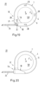
- FIG.10 - 18 are schematic cross sections BB from Fig. 2 to illustrate the possible designs of a heat protection device 2.
- a receiving space 48 of the heat protection device 2 is shown.
- the receiving space 48 is formed by the side walls 6 of the housing 1 and the peripheral wall 4.
- the receiving space 48 here has a U-shaped profile.
- the receiving space 48 is filled with an insulation layer 30.
- the receiving space 48 is closed by the clamp band 22 of the clamp 14.
- the heat protection device 2 has at least two spacer elements 50.
- the spacer elements 50 are arranged between the clamp 14 and the insulation layer 30.
- the spacer elements 50 are introduced laterally on the walls 6 of the housing 1 on the receiving space side.
- An insulating air layer 52 is in the Fig. 12 between the peripheral wall 4 and the insulation layer 30 by appropriately arranged spacer elements 50.
- two insulating air layers 52 are implemented in the radial direction R between the clamp 14 and the insulating layer 30 and between the insulating layer 30 and the housing 1 by means of spacer elements 50.
- the Fig. 14 and 15 show heat protection devices 2 which have two different insulation layers 30, 31.
- the first insulation layer 30 can have a different material than the second insulation layer 31.
- the insulation layers 30, 31 can be connected to one another or separated from one another by an air layer 52.
- the Fig. 16 shows one of the Fig. 10 corresponding embodiment of the heat protection device 2, wherein two insulation layers 30, 31 are used here, which are directly connected to each other and to the clamp 14.
- the insulation layers 30, 31 can be glued to the housing 1 and the clamp 14.
- the insulation layers 30, 31 not only have a planar extension in the axial direction A, but also encompass the clamp 14 in sections in the radial direction R. As a result, the insulation layers 30, 31 also form a U-shape analogous to the receiving space 48. As a result, heat transfer in the axial direction A from the clamp 14 and to the clamp 14 can be prevented or at least dampened.
- the Fig. 18 shows an example in which an air gap can also be formed in the axial direction A between the insulation layers 30, 31 or between an insulation layer 31 and the walls 6 of the housing 1.
- a side view of a clamp arrangement 20 with an overlap section 54 according to an embodiment is shown.
- the overlap section 54 is arranged on a first circumferential end 17 of the housing 1 of the heat protection device 2 and extends in the radial direction R into a receiving section 58 of the clamp arrangement 20.
- a receiving section 58 for example, a component, a pipe, a hose and the like can be received or fastened.
- the overlapping section 54 is rounded in shape corresponding to the clamp arrangement 20 and preferably follows the shape of the receiving section 58. Thus, a continuous support surface of the heat protection device 2 can be provided in the receiving section 58.
- the clamp arrangement 20 is shown in an assembled state in which the overlap section 54 contacts the second end section 18 of the housing 1 on one side and thus prevents interruptions in the heat protection device 2.
- the second end section 18 of the housing 1 forms a second end of the housing 1 of the heat protection device 2 in the circumferential direction U.
- the Fig. 20 shows a side view of a clamp arrangement 20 with an overlap section 54 according to a further embodiment.
- the overlap section 54 is shaped in such a way that it axial direction A, the second end portion 18 of the housing 1 is superimposed at least axially on one side.
- the overlapping section 54 extends the first end 55 of the housing 1 in the circumferential direction U.
- the overlapping section 54 can axially overlap the second end section 18 of the housing 1 on both sides or at least partially encompass the second end section 18 of the housing 1. This can also prevent, for example, the heat protection device 2 from slipping in the connection area between the first end section 17 and the second end section 18.
Landscapes
- Engineering & Computer Science (AREA)
- General Engineering & Computer Science (AREA)
- Mechanical Engineering (AREA)
- Thermal Insulation (AREA)
- Clamps And Clips (AREA)
- Supports For Pipes And Cables (AREA)
Applications Claiming Priority (2)
| Application Number | Priority Date | Filing Date | Title |
|---|---|---|---|
| DE102019121432.7A DE102019121432A1 (de) | 2019-08-08 | 2019-08-08 | Schellenanordnung mit einer Hitzeschutzeinrichtung |
| PCT/EP2020/071795 WO2021023704A1 (de) | 2019-08-08 | 2020-08-03 | Schellenanordnung mit einer hitzeschutzeinrichtung |
Publications (2)
| Publication Number | Publication Date |
|---|---|
| EP4010617A1 EP4010617A1 (de) | 2022-06-15 |
| EP4010617B1 true EP4010617B1 (de) | 2024-10-02 |
Family
ID=71994487
Family Applications (1)
| Application Number | Title | Priority Date | Filing Date |
|---|---|---|---|
| EP20753315.9A Active EP4010617B1 (de) | 2019-08-08 | 2020-08-03 | Schellenanordnung mit einer hitzeschutzeinrichtung |
Country Status (11)
| Country | Link |
|---|---|
| US (1) | US12072058B2 (pl) |
| EP (1) | EP4010617B1 (pl) |
| JP (1) | JP7336023B2 (pl) |
| KR (1) | KR102793248B1 (pl) |
| CN (1) | CN114127454B (pl) |
| DE (1) | DE102019121432A1 (pl) |
| DK (1) | DK4010617T3 (pl) |
| FI (1) | FI4010617T3 (pl) |
| HU (1) | HUE069546T2 (pl) |
| PL (1) | PL4010617T3 (pl) |
| WO (1) | WO2021023704A1 (pl) |
Families Citing this family (4)
| Publication number | Priority date | Publication date | Assignee | Title |
|---|---|---|---|---|
| AU2019280452B2 (en) * | 2018-06-06 | 2024-12-19 | Abey Australia Pty. Ltd. | Damping extrusions |
| US10605382B2 (en) | 2018-08-21 | 2020-03-31 | Anvil International, Llc | Fitting for concentrically loading a brace member |
| US10816108B2 (en) | 2018-08-30 | 2020-10-27 | Anvil International, Llc | Adjustable fitting assembly |
| EP4006396B1 (en) * | 2019-04-02 | 2023-11-01 | Bombardier Inc. | Frangible attachment for fuel line survivability |
Family Cites Families (22)
| Publication number | Priority date | Publication date | Assignee | Title |
|---|---|---|---|---|
| US2379568A (en) * | 1940-08-24 | 1945-07-03 | Adel Prec Products Corp | Conduit supporting clip |
| US2352823A (en) * | 1941-02-03 | 1944-07-04 | Adel Prec Products Corp | Universal support for conduits |
| US2373300A (en) * | 1943-03-20 | 1945-04-10 | Adel Prec Products Corp | Conduit clip |
| US2466921A (en) * | 1945-01-08 | 1949-04-12 | Tinnerman Products Inc | Snap clamp |
| DE925743C (de) * | 1953-12-23 | 1955-03-28 | Ingbuero Hollender & Co | Isolierende und waermefeste Rohrverbindung |
| US3015465A (en) * | 1959-05-11 | 1962-01-02 | Aero Gasket Corp | Support clamp |
| US4441677A (en) * | 1982-04-02 | 1984-04-10 | Ta Mfg., Inc. | Clamp device |
| DE3345179A1 (de) | 1983-12-14 | 1985-06-27 | Schlauch-Handels-Produktions GmbH, 2401 Ratekau | Kompensator fuer leitungen oder dergleichen, die heisse abgase fuehren |
| DE8916031U1 (de) * | 1989-04-11 | 1992-12-24 | Rasmussen Gmbh, 6457 Maintal | Rohrkupplung zum Verbinden der Enden zweier Rohre |
| US5505497A (en) * | 1993-11-15 | 1996-04-09 | Shea; Lawrence E. | Mechanical joint connections for fiberglass reinforced duct sections |
| RU2096676C1 (ru) | 1995-10-27 | 1997-11-20 | Константин Николаевич Деулин | Червячный хомут |
| GB9611410D0 (en) * | 1996-05-31 | 1996-08-07 | Taylor Kerr Couplings Ltd | Pipe coupling |
| JPH1163302A (ja) * | 1997-08-08 | 1999-03-05 | Nhk Spring Co Ltd | 配管用断熱支持装置 |
| DE20014142U1 (de) | 2000-04-22 | 2001-02-22 | Wantoch, Manfred, 44866 Bochum | Rohrkupplung |
| FR2881054B1 (fr) * | 2005-01-25 | 2007-04-06 | Fed Mogul Systems Prot Group S | Gaine de protection thermique |
| DE202010014995U1 (de) * | 2010-10-06 | 2012-01-30 | Anh-Dung Tiêu | Mechanisch - pyrotechnisches Feuerlöschsystem für ein Dach mit und ohne Photovoltaik - Anlage |
| RS55295B1 (sr) | 2012-06-14 | 2017-03-31 | Norma Germany Gmbh | Profilisana obujmica |
| CN104455941B (zh) | 2014-11-11 | 2016-09-14 | 贵州黔南科技塑业有限公司 | 一种保温的管接头 |
| GB2537384B (en) * | 2015-04-14 | 2018-01-03 | Taylor Kerr (Couplings) Ltd | Fire resistant pipe coupling |
| DE102016103687A1 (de) * | 2016-03-01 | 2017-09-07 | Norma Germany Gmbh | Profilschelle mit Dichtelement, Dichtelement für eine Profilschelle und Leitungsverbindungsanordnung mit einer derartigen Profilschelle |
| DE102016107637A1 (de) * | 2016-04-25 | 2017-10-26 | Bdd Beteiligungs Gmbh | Haltevorrichtung zum Befestigen einer Isolierung und Werkzeug hierfür |
| DE102016111117A1 (de) | 2016-06-17 | 2017-12-21 | Norma Germany Gmbh | Schelle mit thermischer Isolationsschicht |
-
2019
- 2019-08-08 DE DE102019121432.7A patent/DE102019121432A1/de not_active Ceased
-
2020
- 2020-08-03 FI FIEP20753315.9T patent/FI4010617T3/en active
- 2020-08-03 DK DK20753315.9T patent/DK4010617T3/da active
- 2020-08-03 US US17/633,698 patent/US12072058B2/en active Active
- 2020-08-03 HU HUE20753315A patent/HUE069546T2/hu unknown
- 2020-08-03 KR KR1020227000978A patent/KR102793248B1/ko active Active
- 2020-08-03 JP JP2022507855A patent/JP7336023B2/ja active Active
- 2020-08-03 CN CN202080050251.4A patent/CN114127454B/zh active Active
- 2020-08-03 WO PCT/EP2020/071795 patent/WO2021023704A1/de not_active Ceased
- 2020-08-03 PL PL20753315.9T patent/PL4010617T3/pl unknown
- 2020-08-03 EP EP20753315.9A patent/EP4010617B1/de active Active
Also Published As
| Publication number | Publication date |
|---|---|
| CN114127454B (zh) | 2024-06-25 |
| CN114127454A (zh) | 2022-03-01 |
| KR20220017503A (ko) | 2022-02-11 |
| DE102019121432A1 (de) | 2021-02-11 |
| PL4010617T3 (pl) | 2025-02-10 |
| JP7336023B2 (ja) | 2023-08-30 |
| FI4010617T3 (en) | 2024-11-20 |
| WO2021023704A1 (de) | 2021-02-11 |
| US20220316647A1 (en) | 2022-10-06 |
| KR102793248B1 (ko) | 2025-04-08 |
| JP2022543485A (ja) | 2022-10-12 |
| EP4010617A1 (de) | 2022-06-15 |
| US12072058B2 (en) | 2024-08-27 |
| HUE069546T2 (hu) | 2025-03-28 |
| DK4010617T3 (da) | 2024-11-18 |
Similar Documents
| Publication | Publication Date | Title |
|---|---|---|
| EP4010617B1 (de) | Schellenanordnung mit einer hitzeschutzeinrichtung | |
| EP2587106B1 (de) | Brandschutzmanschette | |
| DE102015103228B4 (de) | Presshülse, Pressfitting und Verwendung des Pressfittings oder der Presshülse | |
| EP4127543B1 (de) | Steckverbinder mit vormontagesicherung | |
| EP1806528A1 (de) | Verbindungsanordnung mit Rohrstutzen zum Verbinden von Fluidaufnahmeteilen | |
| DE202020101638U1 (de) | Steckverbinder mit Vormontagesicherung | |
| EP4051942B1 (de) | Schnellverbinder und verbindungsanordnung mit verbesserter dichtringarretierung | |
| EP3239586A1 (de) | Haltevorrichtung zum befestigen einer isolierung und werkzeug hierfür | |
| EP3282164B1 (de) | Rohrleitungssystem | |
| EP0982522A2 (de) | Brandschutzvorrichtung | |
| EP3557108B1 (de) | Anschlussvorrichtung für medienleitungen | |
| DE102008034435B4 (de) | Flammschutzeinrichtung für eine Rohrkupplung | |
| EP1967780B1 (de) | Endanschlussmittel für ein Wellrohr | |
| DE102006029242B4 (de) | Flanschverbindung | |
| DE102012216097B4 (de) | Entkoppelelement | |
| DE102019133140A1 (de) | "Leitungsverbinder" | |
| EP3073169B1 (de) | Offenes anbauteil mit federspannung | |
| EP3760908B1 (de) | Rohrleitung und abzweigelement | |
| EP3584487A1 (de) | Rohrbride für verbrennungsluftrohre sowie abgassystem | |
| EP3477174A2 (de) | Brandschutzmanschette sowie gehäuse dafür und diese aufweisende wand- oder deckendurchführung | |
| DE102016119228A1 (de) | Rohrverbindung | |
| EP4421368A2 (de) | Rohrverbund und kunststoffrohrsystem | |
| EP4579111A1 (de) | Dichtung zum endseitigen abdichten eines bauteilabschnitts | |
| DE60012835T2 (de) | Doppelwandiger Rohrabschnitt und Verfahren zur Herstellung von rohrförmigen Elementen | |
| EP3045795B1 (de) | Rohrverbindung |
Legal Events
| Date | Code | Title | Description |
|---|---|---|---|
| STAA | Information on the status of an ep patent application or granted ep patent |
Free format text: STATUS: UNKNOWN |
|
| STAA | Information on the status of an ep patent application or granted ep patent |
Free format text: STATUS: THE INTERNATIONAL PUBLICATION HAS BEEN MADE |
|
| PUAI | Public reference made under article 153(3) epc to a published international application that has entered the european phase |
Free format text: ORIGINAL CODE: 0009012 |
|
| STAA | Information on the status of an ep patent application or granted ep patent |
Free format text: STATUS: REQUEST FOR EXAMINATION WAS MADE |
|
| 17P | Request for examination filed |
Effective date: 20220215 |
|
| AK | Designated contracting states |
Kind code of ref document: A1 Designated state(s): AL AT BE BG CH CY CZ DE DK EE ES FI FR GB GR HR HU IE IS IT LI LT LU LV MC MK MT NL NO PL PT RO RS SE SI SK SM TR |
|
| DAV | Request for validation of the european patent (deleted) | ||
| DAX | Request for extension of the european patent (deleted) | ||
| STAA | Information on the status of an ep patent application or granted ep patent |
Free format text: STATUS: EXAMINATION IS IN PROGRESS |
|
| 17Q | First examination report despatched |
Effective date: 20230607 |
|
| GRAP | Despatch of communication of intention to grant a patent |
Free format text: ORIGINAL CODE: EPIDOSNIGR1 |
|
| STAA | Information on the status of an ep patent application or granted ep patent |
Free format text: STATUS: GRANT OF PATENT IS INTENDED |
|
| GRAS | Grant fee paid |
Free format text: ORIGINAL CODE: EPIDOSNIGR3 |
|
| INTG | Intention to grant announced |
Effective date: 20240704 |
|
| GRAA | (expected) grant |
Free format text: ORIGINAL CODE: 0009210 |
|
| STAA | Information on the status of an ep patent application or granted ep patent |
Free format text: STATUS: THE PATENT HAS BEEN GRANTED |
|
| AK | Designated contracting states |
Kind code of ref document: B1 Designated state(s): AL AT BE BG CH CY CZ DE DK EE ES FI FR GB GR HR HU IE IS IT LI LT LU LV MC MK MT NL NO PL PT RO RS SE SI SK SM TR |
|
| REG | Reference to a national code |
Ref country code: GB Ref legal event code: FG4D Free format text: NOT ENGLISH |
|
| REG | Reference to a national code |
Ref country code: CH Ref legal event code: EP |
|
| REG | Reference to a national code |
Ref country code: DE Ref legal event code: R096 Ref document number: 502020009382 Country of ref document: DE |
|
| REG | Reference to a national code |
Ref country code: IE Ref legal event code: FG4D Free format text: LANGUAGE OF EP DOCUMENT: GERMAN |
|
| REG | Reference to a national code |
Ref country code: DK Ref legal event code: T3 Effective date: 20241112 |
|
| REG | Reference to a national code |
Ref country code: FI Ref legal event code: FGE |
|
| REG | Reference to a national code |
Ref country code: SE Ref legal event code: TRGR |
|
| REG | Reference to a national code |
Ref country code: LT Ref legal event code: MG9D |
|
| REG | Reference to a national code |
Ref country code: NL Ref legal event code: MP Effective date: 20241002 |
|
| REG | Reference to a national code |
Ref country code: SK Ref legal event code: T3 Ref document number: E 45594 Country of ref document: SK |
|
| PG25 | Lapsed in a contracting state [announced via postgrant information from national office to epo] |
Ref country code: NL Free format text: LAPSE BECAUSE OF FAILURE TO SUBMIT A TRANSLATION OF THE DESCRIPTION OR TO PAY THE FEE WITHIN THE PRESCRIBED TIME-LIMIT Effective date: 20241002 |
|
| REG | Reference to a national code |
Ref country code: HU Ref legal event code: AG4A Ref document number: E069546 Country of ref document: HU |
|
| PG25 | Lapsed in a contracting state [announced via postgrant information from national office to epo] |
Ref country code: NL Free format text: LAPSE BECAUSE OF FAILURE TO SUBMIT A TRANSLATION OF THE DESCRIPTION OR TO PAY THE FEE WITHIN THE PRESCRIBED TIME-LIMIT Effective date: 20241002 |
|
| PG25 | Lapsed in a contracting state [announced via postgrant information from national office to epo] |
Ref country code: HR Free format text: LAPSE BECAUSE OF FAILURE TO SUBMIT A TRANSLATION OF THE DESCRIPTION OR TO PAY THE FEE WITHIN THE PRESCRIBED TIME-LIMIT Effective date: 20241002 Ref country code: PT Free format text: LAPSE BECAUSE OF FAILURE TO SUBMIT A TRANSLATION OF THE DESCRIPTION OR TO PAY THE FEE WITHIN THE PRESCRIBED TIME-LIMIT Effective date: 20250203 Ref country code: IS Free format text: LAPSE BECAUSE OF FAILURE TO SUBMIT A TRANSLATION OF THE DESCRIPTION OR TO PAY THE FEE WITHIN THE PRESCRIBED TIME-LIMIT Effective date: 20250202 |
|
| PG25 | Lapsed in a contracting state [announced via postgrant information from national office to epo] |
Ref country code: BG Free format text: LAPSE BECAUSE OF FAILURE TO SUBMIT A TRANSLATION OF THE DESCRIPTION OR TO PAY THE FEE WITHIN THE PRESCRIBED TIME-LIMIT Effective date: 20241002 |
|
| PG25 | Lapsed in a contracting state [announced via postgrant information from national office to epo] |
Ref country code: ES Free format text: LAPSE BECAUSE OF FAILURE TO SUBMIT A TRANSLATION OF THE DESCRIPTION OR TO PAY THE FEE WITHIN THE PRESCRIBED TIME-LIMIT Effective date: 20241002 |
|
| PG25 | Lapsed in a contracting state [announced via postgrant information from national office to epo] |
Ref country code: GR Free format text: LAPSE BECAUSE OF FAILURE TO SUBMIT A TRANSLATION OF THE DESCRIPTION OR TO PAY THE FEE WITHIN THE PRESCRIBED TIME-LIMIT Effective date: 20250103 Ref country code: LV Free format text: LAPSE BECAUSE OF FAILURE TO SUBMIT A TRANSLATION OF THE DESCRIPTION OR TO PAY THE FEE WITHIN THE PRESCRIBED TIME-LIMIT Effective date: 20241002 |
|
| PG25 | Lapsed in a contracting state [announced via postgrant information from national office to epo] |
Ref country code: RS Free format text: LAPSE BECAUSE OF FAILURE TO SUBMIT A TRANSLATION OF THE DESCRIPTION OR TO PAY THE FEE WITHIN THE PRESCRIBED TIME-LIMIT Effective date: 20250102 |
|
| PG25 | Lapsed in a contracting state [announced via postgrant information from national office to epo] |
Ref country code: SM Free format text: LAPSE BECAUSE OF FAILURE TO SUBMIT A TRANSLATION OF THE DESCRIPTION OR TO PAY THE FEE WITHIN THE PRESCRIBED TIME-LIMIT Effective date: 20241002 |
|
| REG | Reference to a national code |
Ref country code: DE Ref legal event code: R097 Ref document number: 502020009382 Country of ref document: DE |
|
| PG25 | Lapsed in a contracting state [announced via postgrant information from national office to epo] |
Ref country code: EE Free format text: LAPSE BECAUSE OF FAILURE TO SUBMIT A TRANSLATION OF THE DESCRIPTION OR TO PAY THE FEE WITHIN THE PRESCRIBED TIME-LIMIT Effective date: 20241002 |
|
| PG25 | Lapsed in a contracting state [announced via postgrant information from national office to epo] |
Ref country code: RO Free format text: LAPSE BECAUSE OF FAILURE TO SUBMIT A TRANSLATION OF THE DESCRIPTION OR TO PAY THE FEE WITHIN THE PRESCRIBED TIME-LIMIT Effective date: 20241002 |
|
| PG25 | Lapsed in a contracting state [announced via postgrant information from national office to epo] |
Ref country code: IT Free format text: LAPSE BECAUSE OF FAILURE TO SUBMIT A TRANSLATION OF THE DESCRIPTION OR TO PAY THE FEE WITHIN THE PRESCRIBED TIME-LIMIT Effective date: 20241002 |
|
| PLBE | No opposition filed within time limit |
Free format text: ORIGINAL CODE: 0009261 |
|
| STAA | Information on the status of an ep patent application or granted ep patent |
Free format text: STATUS: NO OPPOSITION FILED WITHIN TIME LIMIT |
|
| 26N | No opposition filed |
Effective date: 20250703 |
|
| PGFP | Annual fee paid to national office [announced via postgrant information from national office to epo] |
Ref country code: DE Payment date: 20250827 Year of fee payment: 6 |
|
| PGFP | Annual fee paid to national office [announced via postgrant information from national office to epo] |
Ref country code: GB Payment date: 20250827 Year of fee payment: 6 |
|
| PGFP | Annual fee paid to national office [announced via postgrant information from national office to epo] |
Ref country code: FR Payment date: 20250825 Year of fee payment: 6 |