EP4009769B1 - Werkzeugloser falzteiler für einen mähdrescher - Google Patents
Werkzeugloser falzteiler für einen mähdrescher Download PDFInfo
- Publication number
- EP4009769B1 EP4009769B1 EP20761045.2A EP20761045A EP4009769B1 EP 4009769 B1 EP4009769 B1 EP 4009769B1 EP 20761045 A EP20761045 A EP 20761045A EP 4009769 B1 EP4009769 B1 EP 4009769B1
- Authority
- EP
- European Patent Office
- Prior art keywords
- header
- adjustable connector
- divider
- frame
- receiving
- Prior art date
- Legal status (The legal status is an assumption and is not a legal conclusion. Google has not performed a legal analysis and makes no representation as to the accuracy of the status listed.)
- Active
Links
Images

Classifications
-
- A—HUMAN NECESSITIES
- A01—AGRICULTURE; FORESTRY; ANIMAL HUSBANDRY; HUNTING; TRAPPING; FISHING
- A01D—HARVESTING; MOWING
- A01D63/00—Outside dividers
-
- A—HUMAN NECESSITIES
- A01—AGRICULTURE; FORESTRY; ANIMAL HUSBANDRY; HUNTING; TRAPPING; FISHING
- A01D—HARVESTING; MOWING
- A01D41/00—Combines, i.e. harvesters or mowers combined with threshing devices
- A01D41/12—Details of combines
- A01D41/14—Mowing tables
-
- A—HUMAN NECESSITIES
- A01—AGRICULTURE; FORESTRY; ANIMAL HUSBANDRY; HUNTING; TRAPPING; FISHING
- A01D—HARVESTING; MOWING
- A01D45/00—Harvesting of standing crops
- A01D45/02—Harvesting of standing crops of maize, i.e. kernel harvesting
- A01D45/021—Cornheaders
-
- A—HUMAN NECESSITIES
- A01—AGRICULTURE; FORESTRY; ANIMAL HUSBANDRY; HUNTING; TRAPPING; FISHING
- A01D—HARVESTING; MOWING
- A01D47/00—Headers for topping of plants, e.g. stalks with ears
-
- A—HUMAN NECESSITIES
- A01—AGRICULTURE; FORESTRY; ANIMAL HUSBANDRY; HUNTING; TRAPPING; FISHING
- A01D—HARVESTING; MOWING
- A01D63/00—Outside dividers
- A01D63/02—Rotating dividers
-
- A—HUMAN NECESSITIES
- A01—AGRICULTURE; FORESTRY; ANIMAL HUSBANDRY; HUNTING; TRAPPING; FISHING
- A01D—HARVESTING; MOWING
- A01D63/00—Outside dividers
- A01D63/04—Non-rotating dividers
Definitions
- the present invention pertains to agricultural headers and, more specifically, to lateral end dividers for agricultural headers.
- a combine An agricultural harvester known as a "combine” is historically termed such because it combines multiple harvesting functions with a single harvesting unit, such as picking, threshing, separating, and cleaning.
- a combine includes a header which removes the crop from a field and a feeder housing which transports the crop material into a threshing rotor.
- the threshing rotor rotates within a perforated housing, which may be in the form of adjustable concaves, and performs a threshing operation on the crop to remove the grain.
- the threshing rotor is provided with rasp bars that interact with the crop material in order to further separate the grain from the crop material, and to provide positive crop movement. Once the grain is threshed, the grain is cleaned using a cleaning system.
- the cleaning system includes a cleaning fan which blows air through oscillating sieves to discharge chaff and other debris toward the rear of the combine.
- Non-grain crop material, such as straw, from the threshing section proceeds through a straw chopper and out the rear of the combine. Clean grain is transported to a grain tank onboard the combine.
- a typical header generally includes a frame, a pair of end dividers at the lateral ends of the frame, a floor, a cutter to remove crop material from the field, and a conveyor to transport the cut crop material to the feeder housing for further downstream processing in the combine.
- the components of a header are specifically optimized to harvest a particular kind of crop.
- the header may be in the form of a draper header which is typically used to harvest fluffy or bushy crop such as soy beans or canola.
- a draper header generally includes a rotating reel assembly with tines, a cutter bar, and a conveyor in the form of one or more draper belts and/or augers. Some draper headers may also move, e.g. lower, raise, roll, pitch, and/or flex, to accommodate the undulating terrain of the field.
- the header is typically removed from the combine, positioned on a header-specific transport trailer, and towed lengthwise behind a transport vehicle. Even with transporting the header separately, various components, such as the end dividers, may nevertheless need to be removed in order to reduce the width of the header during transportation.
- the removal of the dividers from the header requires the use of tools and a location to store the dividers during transportation of the header.
- removing the dividers may increase the time involved in transporting a header.
- the removal of the dividers may increase the possibility of the operator forgetting, or otherwise losing, parts of the dividers and/or header during transportation.
- US-A1-2014/083074 describes a retrofit hinge kit adapted for use with square tube frames to allow crop dividers to pivot out of the way for transport.
- a header for an agricultural vehicle in accordance with claim 1 that includes a frame, a receiving member connected to the frame of the header, and at least one divider movably connected to the frame.
- the at least one divider includes a divider body and an adjustable connector positionable in an unfolded work position and a folded transport position.
- the adjustable connector includes a first member, a second member, and an articulating joint for pivotally connecting the first and second members.
- the first member mounts the divider body, the second member is slidably connected to and received within the receiving member, and the articulating joint is at least partially received within the receiving member in the unfolded work position such that the first and second members are immobilized and the articulating joint is positioned outside of the receiving member in the folded transport position such that the first and second members are movable relative to one another.
- the method includes the initial step of providing a divider that includes a divider body, a receiving member configured for being connected to the frame of the header, and an adjustable connector positionable in an unfolded work position and a folded transport position.
- the adjustable connector includes a first member, a second member, and an articulating j oint for pivotally connecting the first and second members.
- the first member mounts the divider body and the second member is slidably connected to and received within the receiving member.
- the method also includes a step of positioning the adjustable connector in one of: the folded transport position by sliding the adjustable connecter outwardly away from the receiving member such that the articulating joint is positioned outside of the receiving member and the first and second members are movable relative to one another, and folding the first member inwardly for folding the divider body inwardly, and the unfolded work position by unfolding the first member and the second member and sliding the adjustable connecter further within the receiving member such that the articulating joint is at least partially received within the receiving member and the first and second members are immobilized
- One possible advantage of the exemplary embodiment of the agricultural header is that the end dividers may be folded inwardly into a transport position without the need for additional tools.
- Another possible advantage of the exemplary embodiment of the agricultural header is that the end dividers remain attached to the header in the work and transport positions.
- forward when used in connection with the agricultural harvester and/or components thereof are usually determined with reference to the direction of forward operative travel of the harvester, but again, they should not be construed as limiting.
- longitudinal and “transverse” are determined with reference to the fore- and-aft direction of the agricultural harvester and are equally not to be construed as limiting.
- downstream and “upstream” are determined with reference to the intended direction of crop material flow during operation, with “downstream” being analogous to "rearward” and “upstream” being analogous to "forward.”
- the agricultural vehicle 100 is illustrated as a combine 100, which generally includes a chassis 102 supported by wheels, a prime mover, a cab, a feeder housing, and a header 110.
- the header 110 is removably attached to the feeder housing.
- the header 110 is in the form of a draper header 110.
- the draper header 110 generally includes a frame 112, a cutter bar 114 that severs the crop from a field, at least one conveyor 116, for example a draper belt 116 and/or auger, which feeds the severed crop inwardly toward the feeder housing, a pair of lateral end dividers 118, and a reel assembly 120 mounted to the frame 112, which feeds the crop into the header 110.
- the reel assembly 120 generally includes a rotating reel 122 with fingers, e.g. tines 124, a pair of "L"-shaped reel arms 126 mounting the reel 122 to the frame 112, a pair of extension hydraulic cylinders 127, a respective pair of lifting hydraulic cylinders 128, and a reel bearing 129.
- the reel assembly 120 may also include a reel drive mechanism for rotating the reel. Thereby, the reel 122 may be raised and lowered by the actuators 128 or extended and retracted by the actuators 127.
- Each reel arm 126 has a proximal, i.e., rear, end and a distal, i.e., front, end. The proximal end of each reel arm 126 is pivotally connected to the frame 112.
- the reel 122 is movably mounted onto each distal end of the reel arms 126 by way of the reel bearing 129.
- Each reel arm 126 is a rigid, uniform part that is typically composed of metal.
- the header 110 In order to transport the header 110 along roadways, the header 110 must generally be positioned on a header transport trailer and detached from the agricultural vehicle 100. Then, the header 110 may be towed lengthwise with its longitudinal axis being parallel to the forward direction of travel. Nevertheless, the width of the header 110 in the transport position may still be too great for some roadway requirements. Thereby, the operator generally has to completely remove one or more components from the header 110 to reduce the width of the header 110 in the transport position. For instance, the operator can remove the end dividers 118 to reduce the lateral profile of the header 110. As can be appreciated, it may be undesirable to attach and reattach the end dividers 118 as this process is time consuming and requires separate tools and a place to temporarily store the detached end dividers 118.
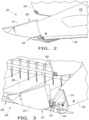
- a header 200 in the form of a draper header 200, which generally includes a frame 202, a cutter bar 204, at least one conveyor 206, and a reel assembly 208.
- the header 200 may also include at least one foldable crop divider 210, such as a pair of end dividers 210 located at each lateral end of the header 200 (only one shown).
- the header 200 is shown as a draper header 200, it should be appreciated that the end dividers 210 may be incorporated into any desired header 200.
- Each divider 210 may generally include a divider body 212, a receiving member 214 connected to the frame 202, and an adjustable connector 216 ( FIG. 3 ). Each divider 210 is movably connected to the frame 202 such that each divider 210 is foldable between an unfolded work position ( FIG. 2 ) and a folded transport position ( FIG. 3 ). Thereby, the overall profile, i.e., width, of the header 200 may be reduced in the transport position. Each divider 210 may also include a locking member 218 connected to the frame 202 of the header 200 for selectively locking each respective divider 210 in the work and transport positions ( FIG. 3 ).
- the divider body 212 is connected to the adjustable connector 216.
- the divider body 212 may be fastened to the adjustable connector 216 by one or more fasteners.
- the divider body 212 may comprise any desired material and shape.
- the divider body 212 may comprise a shell body made from sheet metal and a substantially triangular cross-section.
- the receiving member 214 mounts the adjustable connector 216 to the header 200.
- the receiving member 214 may be in the form of a receiving tube 214 which slidably receives the adjustable connector 216.
- the receiving tube 214 defines an internal receiving hole for slidably receiving the adjustable connector 216.
- the receiving tube 214 may also have one or more bottom slots which allow the locking member 218 to pass therethrough and engage with the adjustable connector 216.
- the receiving member 214 may comprise any desired material and shape.
- the receiving member 214 may be connected to or incorporated as part of the frame 202 of the header 200. For example, the receiving member 214 may be welded to the frame 202 of the header 200.
- the receiving member 214 may be a member of a respective divider 210 or a separate member connected to the header 200.
- the adjustable connector 216 may slide and pivot relative to the header 200.
- the adjustable connector 216 may be slidably connected to the receiving member 214 and may also pivot in order to rotate the divider body 212 between the work and transport positions.
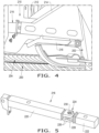
- the adjustable connector 216 may include a first member 220 which mounts the divider body 212, a second member 222 that is slidably connected to and received within the receiving member 214, and an articulating joint 224 for pivotally connecting the first and second members 220, 222 ( FIG. 5 ).
- the adjustable connector 216 may be positioned in the work position in which the articulating joint 224 is at least partially received within the receiving member 214 and the first and second members 220, 222 are parallel to one another.
- substantially immobilized may refer to how the first member 220 is restricted from rotating as it contacts the inside perimeter of the receiving member 214, when the articulating joint is at least partially within the receiving member 214. Any movement of the first member 220 in the work position may be negligible and caused by tolerances between the adjustable connector 216 and the receiving member 214.
- the adjustable connector 216 may also be positioned in the transport position in which the articulating joint 224 is positioned outside of the receiving member 214 such that the first and second members 220, 222 are movable relative to one another and folded to be substantially perpendicular to one another.
- the divider 210 In the transport position, the divider 210 is not rigid and may be folded inwardly such that it is substantially parallel with the longitudinal axis of the frame 202 ( FIG. 3 ). Hence, as the first member 220 folds inwardly or outwardly, the divider body 212 also folds inwardly or outwardly.
- the adjustable connector 216 remains connected to the receiving member 214 in the work position and the transport position.
- the adjustable connector 216 may comprise any desired material and shape.
- the first and second members 220, 222 may each include at least one mating protrusion 226, 228 ( FIG. 5 ) which mate, e.g. overlap, with one another and define the articulating j oint 224.
- the first member 220 may include a pair of mating protrusions 226, and the second member 222 may include a single mating protrusion 228 positioned in between the pair of mating protrusions 226 of the first member 220, or vice versa. It is also conceivable for each member 220, 222 to include a single mating protrusion.
- the mating protrusions 226, 228 may each include a receiving hole for receiving a fastener 230, e.g.
- the articulating joint 224 is comprised of the mating protrusions 226, 228 and the fastener 230.
- the first member 220 and the second member 222 of the adjustable connector 216 may be in the form of a mounting tube 220 and a telescoping tube 222 which slides in and out of the receiving member 214.
- the tubes 220, 222 may be square tubes; however, the first and second members 220, 222 may comprise any desired material and shape, e.g. round, hexagonal, etc.
- the first member 220 and/or the second member 222 may have a configuration which is tubular, a solid body, and/or a casting.
- first member 220 and/or the second member 222 may each be in the form of an inverted "T"-shaped casting.
- the articulating joint 224 is designed as part of the divider 210 and the receiving member 214 is attached to the frame 202, this configuration could be switched so that the articulating joint 214 is on the frame 202 and the receiving member 214 is connected to the divider body 212.
- the locking member 218 is connected to the frame 202.
- the locking member 218 selectively engages with the adjustable connector 216 and prevents the adjustable connector 218 from sliding relative to the receiving member 214.
- the locking member 218 may have one or more protrusions which engage with one or more receiving portions on the second member 222 of the adjustable connector 216.
- the locking member 218 is a latch 218 that is pivotally connected to the frame 202, underneath the receiving member 214.
- the latch 218 may be a spring-loaded latch that is biased to engaged with and apply a locking force with the second member 222 of the adjustable connector 216.
- the latch 218 may automatically lock the adjustable connector 216 in the work position and the operator may pivot the latch 218 downwardly to disengage the latch 218 from the adjustable connector 216 to slide and fold the divider 210 in the transport position.
- the locking member 218 may be in the form of any desired locking member, such as a pin, a clasp, a hook, a fastener, and/or or one or more protrusions or detents.
- the operator of the header 200 may selectively position each divider 210 in the work position or the transport position. To position each divider 210 in the transport position, the operator may disengage the locking member 218 to allow the adjustable connector 216 to slide relative to the receiving member 214. Then, the adjustable connector 216 may be slid outwardly away from the receiving member 214 such that the articulating joint 224 is positioned outside of the receiving member 214 and the first and second members 220, 222 are movable relative to one another. Then, the first member 220 may be folded inwardly to thereby fold the divider body 212 inwardly.
- first and second member 220, 222 may be unfolded and the entire adjustable connecter 216 may be slid inwardly within the receiving member 214 such that the articulating joint 224 is at least partially received within the receiving member 214 and the first and second members 220, 222 are substantially immobilized.
- the step of positioning the adjustable connector 216 in the work position does not require disengaging the locking member 218 before sliding the adjustable connector 216 within the receiving member 214.
Landscapes
- Life Sciences & Earth Sciences (AREA)
- Environmental Sciences (AREA)
- Agricultural Machines (AREA)
Claims (11)
- Erntevorsatz (200) für ein landwirtschaftliches Fahrzeug (100), mit:einem Rahmen (202);einem Aufnahmeelement (214), das mit dem Rahmen (202) des Erntevorsatzes (200) verbunden ist; undmindestens einer Teilereinrichtung (210), die an dem Rahmen (202) beweglich befestigt ist, wobei die mindestens eine Teilereinrichtung (210) Folgendes umfasst:einen Teilerkörper (212); undein einstellbares Verbindungselement (216), das in einer ausgeklappten Arbeitsposition und in einer eingeklappten Transportposition anordenbar ist, wobei das einstellbare Verbindungselement (216) ein erstes Element (220), ein zweites Element (222), und eine Gelenkverbindungseinrichtung (224) zum schwenkbaren Verbinden des ersten und des zweiten Elements umfasst, wobei das erste Element (220) den Teilerkörper (212) befestigt, und wobei das zweite Element (222) in dem Aufnahmeelement (214) und mit demselben gleitbeweglich verbunden ist,dadurch gekennzeichnet, dassdie Gelenkverbindungseinrichtung (224) mindestens teilweise in dem Aufnahmeelement (214) in der ausgeklappten Arbeitsposition derart aufgenommen ist, dass das erste und das zweite Element (220, 222) fixiert sind, und die Gelenkverbindungseinrichtung (224) außerhalb des Aufnahmeelements (214) in der eingeklappten Transportposition derart angeordnet ist, dass das erste und das zweite Element (220, 222) relativ zueinander beweglich sind.
- Erntevorsatz nach Anspruch 1, wobei das einstellbare Verbindungselement (216) mit dem Aufnahmeelement (214) in der ausgeklappten Arbeitsposition und in der eingeklappten Transportposition verbunden bleibt, und wobei das erste Element (220) zum Falten des Teilerkörpers (212) in die eingeklappte Transportposition nach innen klappt.
- Erntevorsatz nach Anspruch 1, weiterhin aufweisend ein Verriegelungselement (218), das mit dem Rahmen (202) des Erntevorsatzes (200) verbunden ist, wobei das Verriegelungselement (218) wahlweise mit dem einstellbaren Verbindungselement (216) in Eingriff steht und verhindert, dass das einstellbare Verbindungselement (216) eine Gleitbewegung ausführt.
- Erntevorsatz nach Anspruch 3, wobei das Verriegelungselement (218) in Form einer Sperrklinke vorgesehen ist, die mit dem Rahmen (202) des Erntevorsatzes (200) schwenkbar verbunden ist.
- Erntevorsatz nach Anspruch 1, wobei das erste Element (220) mindestens einen Passvorsprung (226) aufweist und das zweite Element (222) mindestens einen Gegenvorsprung (228) aufweist, der derart eingerichtet ist, dass er mit dem mindestens einen Passvorsprung (226) des ersten Elements (220) ineinandergreift.
- Erntevorsatz nach Anspruch 5, wobei das erste Element (220) ein Paar von Passvorsprüngen (226) aufweist und das zweite Element (222) einen einzelnen Gegenvorsprung (228) aufweist, der zwischen dem Paar von Passvorsprüngen (226) des ersten Elements (220) angeordnet ist.
- Erntevorsatz nach Anspruch 5, wobei der mindestens eine Passvorsprung (226) des ersten Elements (220) und der mindestens eine Gegenvorsprung (228) des zweiten Elements (222) einander überlappen.
- Erntevorsatz nach Anspruch 7, weiterhin aufweisend ein Befestigungselement (230), wobei der mindestens eine Passvorsprung (226) des ersten Elements (220) und der mindestens eine Gegenvorsprung (228) des zweiten Elements (222) jeweils eine Aufnahmeöffnung zum Aufnehmen des Befestigungselements (230) aufweisen, und wobei die Gelenkverbindungseinrichtung (224) aus dem mindestens einen Passvorsprung (226) des ersten Elements (220), dem mindestens einen Gegenvorsprung (228) des zweiten Elements (222) und dem Befestigungselement (230) besteht.
- Verfahren zum Betreiben eines Erntevorsatzes (200) mit einem Rahmen (202), für ein landwirtschaftliches Fahrzeug (100), wobei der Erntevorsatz (200) weiterhin eine Teilereinrichtung (210) mit einem Teilerkörper (212), ein Aufnahmeelement (214), das dazu eingerichtet ist, mit dem Rahmen (202) des Erntevorsatzes (200) verbunden zu sein, und ein einstellbares Verbindungselement (216), das in einer ausgeklappten Arbeitsposition und in einer eingeklappten Transportposition anordenbar ist, aufweist, wobei das einstellbare Verbindungselement (216) ein erstes Element (220), ein zweites Element (222), und eine Gelenkverbindungseinrichtung (224) zum schwenkbeweglichen Verbinden des ersten und des zweiten Elements (220, 222) aufweist, wobei das erste Element (220) den Teilerkörper (212) befestigt, wobei das zweite Element (222) in dem Aufnahmeelement (214) und mit demselben gleitbeweglich verbunden ist, und wobei das Verfahren die folgenden Schritte umfasst:
Anordnen des einstellbaren Verbindungselements (216) in einer der folgenden Positionen:in der eingeklappten Transportposition durch das Gleitbewegen des einstellbaren Verbindungselements (216) nach außen weg von dem Aufnahmeelement (214) derart, dass die Gelenkverbindungseinrichtung (224) außerhalb des Aufnahmeelements (214) angeordnet ist und das erste und das zweite Element (220, 222) relativ zueinander beweglich sind, und nach innen Einklappen des ersten Elements (220) zum Falten des Teilerkörpers (212); undin der ausgeklappten Arbeitsposition durch das Ausklappen des ersten Elements (220) und des zweiten Elements (222) und durch das Gleitbewegen des einstellbaren Verbindungselements (216) weiter in das Aufnahmeelement (214) derart, dass die Gelenkverbindungseinrichtung (224) mindestens teilweise in dem Aufnahmeelement (214) aufgenommen ist und das erste und das zweite Element (220, 222) fixiert sind. - Verfahren nach Anspruch 9, wobei die Teilereinrichtung (210) weiterhin ein Verriegelungselement (218) umfasst, das dazu eingerichtet ist, mit dem Rahmen (202) des Erntevorsatzes (200) verbunden zu sein, und wobei das Verriegelungselement (218) wahlweise mit dem einstellbaren Verbindungselement (216) in Eingriff steht und verhindert, dass das einstellbare Verbindungselement (216) eine Gleitbewegung ausführt, und wobei der Schritt des Anordnens des einstellbaren Verbindungselements (216) in der eingeklappten Transportposition weiterhin das Lösen des Verriegelungselements (218) vor der Gleitbewegung des einstellbaren Verbindungselements (216) umfasst.
- Verfahren nach Anspruch 9, wobei die Teilereinrichtung (210) weiterhin ein Verriegelungselement (218) umfasst, das dazu eingerichtet ist, mit dem Rahmen (202) des Erntevorsatzes (200) verbunden zu sein, wobei das Verriegelungselement (218) wahlweise mit dem einstellbaren Verbindungselement (216) in Eingriff steht und verhindert, dass das einstellbare Verbindungselement (216) eine Gleitbewegung ausführt, und wobei der Schritt des Anordnens des einstellbaren Verbindungselements (216) in der eingeklappten Transportposition ein Lösen des Verriegelungselements (218) vor der Gleitbewegung des einstellbaren Verbindungselements (216) nicht erfordert.
Applications Claiming Priority (2)
| Application Number | Priority Date | Filing Date | Title |
|---|---|---|---|
| US16/534,320 US11234371B2 (en) | 2019-08-07 | 2019-08-07 | Tool-less folding divider for combine head |
| PCT/US2020/045428 WO2021026463A1 (en) | 2019-08-07 | 2020-08-07 | Tool-less folding divider for combine head |
Publications (2)
| Publication Number | Publication Date |
|---|---|
| EP4009769A1 EP4009769A1 (de) | 2022-06-15 |
| EP4009769B1 true EP4009769B1 (de) | 2024-12-11 |
Family
ID=72193629
Family Applications (1)
| Application Number | Title | Priority Date | Filing Date |
|---|---|---|---|
| EP20761045.2A Active EP4009769B1 (de) | 2019-08-07 | 2020-08-07 | Werkzeugloser falzteiler für einen mähdrescher |
Country Status (4)
| Country | Link |
|---|---|
| US (1) | US11234371B2 (de) |
| EP (1) | EP4009769B1 (de) |
| AR (1) | AR119593A1 (de) |
| WO (1) | WO2021026463A1 (de) |
Families Citing this family (3)
| Publication number | Priority date | Publication date | Assignee | Title |
|---|---|---|---|---|
| WO2020101841A1 (en) * | 2018-11-16 | 2020-05-22 | Cnh Industrial America Llc | Locking mechanism for an agricultural header |
| WO2021059028A1 (en) * | 2019-09-24 | 2021-04-01 | Agco Corporation | Cutting tools for harvesting header dividers, harvesting headers carrying such tools, and related methods |
| US12520765B2 (en) * | 2020-05-01 | 2026-01-13 | Cnh Industrial America Llc | Systems and methods for toolless crop divider adjustment |
Family Cites Families (35)
| Publication number | Priority date | Publication date | Assignee | Title |
|---|---|---|---|---|
| DE7342482U (de) | 1974-03-28 | Gebr Claas Gmbh | Mehrreihiger Maispflückvorsatz für Mähdrescher | |
| DE119853C (de) | 1900-02-08 | 1901-04-24 | ||
| US703497A (en) * | 1902-04-21 | 1902-07-01 | John F Steward | Grain-divider for harvesters. |
| US1008283A (en) | 1911-04-08 | 1911-11-07 | Deere & Co | Grain-divider for harvesters. |
| US2209047A (en) * | 1939-04-15 | 1940-07-23 | Int Harvester Co | Harvester |
| US2895757A (en) * | 1955-07-14 | 1959-07-21 | John Charles Scoras | Handle |
| US3563592A (en) * | 1969-02-19 | 1971-02-16 | Robert Preston | Lockable folding brace system |
| US3585790A (en) * | 1969-05-26 | 1971-06-22 | Lester Kalkwarf | Corn harvester split adjustable snout construction |
| BE759517A (fr) | 1969-11-27 | 1971-04-30 | Braud Ets | Moissonneuse-batteuse avec avant-train a diviseurs de recolte escamotables |
| US4087954A (en) | 1976-06-11 | 1978-05-09 | Reese Sr Arthur | Retractable crop gathering finger construction |
| DE3048327A1 (de) * | 1980-12-20 | 1982-07-29 | Claas Ohg, 4834 Harsewinkel | Erntevorsatz fuer in reihen stehendes erntegut |
| US4538404A (en) * | 1983-08-16 | 1985-09-03 | General Dryer Corporation | Adjustable crop divider apparatus |
| DE3578030D1 (de) * | 1985-09-14 | 1990-07-12 | Deere & Co | Halmteiler fuer landwirtschaftliche maschinen. |
| US4757673A (en) * | 1986-07-29 | 1988-07-19 | Charles Gayman | Adjustment of crop dividers |
| DE4135884A1 (de) | 1991-10-31 | 1993-05-06 | Claas Ohg, 4834 Harsewinkel, De | Maehdrescher mit halmteiler |
| US5865019A (en) * | 1996-12-17 | 1999-02-02 | New Holland North America, Inc. | Plastic divider assembly with frame for a corn head |
| DE19911827A1 (de) | 1999-03-17 | 2000-09-28 | Deere & Co | Halmteiler |
| US6247297B1 (en) * | 1999-08-20 | 2001-06-19 | Case Corporation | Jackknife support system for a combine cornhead |
| DE10039097A1 (de) * | 2000-08-07 | 2002-02-21 | Claas Saulgau Gmbh | Verfahren und Vorrichtung zum Schwenken der Abteiler von mehrteiligen landwirtschaftlichen Erntemaschinen |
| US6513313B1 (en) * | 2000-09-08 | 2003-02-04 | Case, Llc | Support structure for a divider of an agricultural corn head |
| DE10146768A1 (de) * | 2001-09-22 | 2003-04-10 | Deere & Co | Halmteiler |
| DE10221983A1 (de) * | 2002-05-17 | 2003-11-27 | Kemper Gmbh Maschf | Erntevorsatz |
| GB2392600A (en) * | 2002-09-04 | 2004-03-10 | Cnh Belgium Nv | Cutting platform for a combine harvester |
| DE10303990A1 (de) * | 2003-02-01 | 2004-08-05 | Deere & Company, Moline | Halmteiler |
| BRPI0700408B1 (pt) * | 2006-02-17 | 2016-04-19 | Deere & Co | conjunto de ponta e tampa para um cabeçote de colheita de fileira |
| US7681387B2 (en) * | 2007-07-25 | 2010-03-23 | Deere & Company | Tilt out corn head end fender |
| US8141331B2 (en) * | 2010-04-20 | 2012-03-27 | Cnh America Llc | Divider support apparatus with integral adjustable torsional preload mechanism and vibration damper |
| US8640434B2 (en) * | 2010-08-19 | 2014-02-04 | Agco Corporation | Removable corn header snout |
| US8387352B2 (en) * | 2011-05-20 | 2013-03-05 | Deere & Company | Cornhead divider lift assist linkage |
| US9253944B2 (en) * | 2012-11-12 | 2016-02-09 | Dragotec Usa, Inc. | Snout height and tension adjustment |
| US9032700B2 (en) * | 2013-03-13 | 2015-05-19 | Agco Corporation | Folding divider assembly for corn header and method of operation |
| US8726623B2 (en) * | 2013-08-16 | 2014-05-20 | Divider Hinges Llc | Crop divider hinge kit and method |
| US9226447B2 (en) | 2013-11-01 | 2016-01-05 | Cnh Industrial America Llc | End divider for a header of an agricultural harvester |
| BE1021401B1 (nl) * | 2014-09-03 | 2015-11-16 | Cnh Industrial Belgium Nv | Inklapbare gewasmaaier |
| US9532505B2 (en) * | 2014-12-24 | 2017-01-03 | Cnh Industrial America Llc | Hood divider adjustment apparatus for an agricultural harvester |
-
2019
- 2019-08-07 US US16/534,320 patent/US11234371B2/en active Active
-
2020
- 2020-08-05 AR ARP200102216A patent/AR119593A1/es active IP Right Grant
- 2020-08-07 WO PCT/US2020/045428 patent/WO2021026463A1/en not_active Ceased
- 2020-08-07 EP EP20761045.2A patent/EP4009769B1/de active Active
Also Published As
| Publication number | Publication date |
|---|---|
| WO2021026463A1 (en) | 2021-02-11 |
| EP4009769A1 (de) | 2022-06-15 |
| US11234371B2 (en) | 2022-02-01 |
| AR119593A1 (es) | 2021-12-29 |
| US20210037712A1 (en) | 2021-02-11 |
Similar Documents
| Publication | Publication Date | Title |
|---|---|---|
| USRE49178E1 (en) | Agricultural machine with folding header | |
| US9992924B2 (en) | Folding mechanism for wide wheat headers | |
| EP4009769B1 (de) | Werkzeugloser falzteiler für einen mähdrescher | |
| EP3406130B1 (de) | Landwirtschaftliche maschine mit faltbarem arbeitsagregat | |
| EP3639642B1 (de) | Seitliche transportanordnung für einen landwirtschaftlichen erntevorsatz | |
| EP3034325A1 (de) | Landwirtschaftliche erntemaschinenachse | |
| EP3772270A1 (de) | Automatische verriegelung eines vorsatzs | |
| US12329052B2 (en) | Agricultural header with dolly carried by gauge wheel arm | |
| EP2798938B1 (de) | Zugangsstufe für eine landwirtschaftliche Maschine | |
| EP2854502B1 (de) | Faltschneckenanordnung für eine landwirtschaftliche erntemaschine | |
| US12507631B2 (en) | Divider points, harvesting headers configured to receive removable divider points, and related methods | |
| US12369512B2 (en) | Agricultural header with foldable transport wheel assembly | |
| EP3618603B1 (de) | Übertotpunktverriegelungssystem für einen spreukasten einer landwirtschaftlichen erntemaschine | |
| US12490666B2 (en) | Agricultural header with steerable rear wheel assembly | |
| US10729057B2 (en) | Integrated upright header transport for an agricultural combine |
Legal Events
| Date | Code | Title | Description |
|---|---|---|---|
| STAA | Information on the status of an ep patent application or granted ep patent |
Free format text: STATUS: UNKNOWN |
|
| STAA | Information on the status of an ep patent application or granted ep patent |
Free format text: STATUS: THE INTERNATIONAL PUBLICATION HAS BEEN MADE |
|
| PUAI | Public reference made under article 153(3) epc to a published international application that has entered the european phase |
Free format text: ORIGINAL CODE: 0009012 |
|
| STAA | Information on the status of an ep patent application or granted ep patent |
Free format text: STATUS: REQUEST FOR EXAMINATION WAS MADE |
|
| 17P | Request for examination filed |
Effective date: 20220307 |
|
| AK | Designated contracting states |
Kind code of ref document: A1 Designated state(s): AL AT BE BG CH CY CZ DE DK EE ES FI FR GB GR HR HU IE IS IT LI LT LU LV MC MK MT NL NO PL PT RO RS SE SI SK SM TR |
|
| DAV | Request for validation of the european patent (deleted) | ||
| DAX | Request for extension of the european patent (deleted) | ||
| GRAP | Despatch of communication of intention to grant a patent |
Free format text: ORIGINAL CODE: EPIDOSNIGR1 |
|
| STAA | Information on the status of an ep patent application or granted ep patent |
Free format text: STATUS: GRANT OF PATENT IS INTENDED |
|
| INTG | Intention to grant announced |
Effective date: 20240704 |
|
| GRAS | Grant fee paid |
Free format text: ORIGINAL CODE: EPIDOSNIGR3 |
|
| GRAA | (expected) grant |
Free format text: ORIGINAL CODE: 0009210 |
|
| STAA | Information on the status of an ep patent application or granted ep patent |
Free format text: STATUS: THE PATENT HAS BEEN GRANTED |
|
| AK | Designated contracting states |
Kind code of ref document: B1 Designated state(s): AL AT BE BG CH CY CZ DE DK EE ES FI FR GB GR HR HU IE IS IT LI LT LU LV MC MK MT NL NO PL PT RO RS SE SI SK SM TR |
|
| REG | Reference to a national code |
Ref country code: GB Ref legal event code: FG4D |
|
| REG | Reference to a national code |
Ref country code: CH Ref legal event code: EP |
|
| REG | Reference to a national code |
Ref country code: IE Ref legal event code: FG4D |
|
| REG | Reference to a national code |
Ref country code: DE Ref legal event code: R096 Ref document number: 602020042989 Country of ref document: DE |
|
| REG | Reference to a national code |
Ref country code: LT Ref legal event code: MG9D |
|
| PG25 | Lapsed in a contracting state [announced via postgrant information from national office to epo] |
Ref country code: HR Free format text: LAPSE BECAUSE OF FAILURE TO SUBMIT A TRANSLATION OF THE DESCRIPTION OR TO PAY THE FEE WITHIN THE PRESCRIBED TIME-LIMIT Effective date: 20241211 |
|
| PG25 | Lapsed in a contracting state [announced via postgrant information from national office to epo] |
Ref country code: FI Free format text: LAPSE BECAUSE OF FAILURE TO SUBMIT A TRANSLATION OF THE DESCRIPTION OR TO PAY THE FEE WITHIN THE PRESCRIBED TIME-LIMIT Effective date: 20241211 |
|
| PG25 | Lapsed in a contracting state [announced via postgrant information from national office to epo] |
Ref country code: BG Free format text: LAPSE BECAUSE OF FAILURE TO SUBMIT A TRANSLATION OF THE DESCRIPTION OR TO PAY THE FEE WITHIN THE PRESCRIBED TIME-LIMIT Effective date: 20241211 |
|
| REG | Reference to a national code |
Ref country code: NL Ref legal event code: MP Effective date: 20241211 |
|
| PG25 | Lapsed in a contracting state [announced via postgrant information from national office to epo] |
Ref country code: ES Free format text: LAPSE BECAUSE OF FAILURE TO SUBMIT A TRANSLATION OF THE DESCRIPTION OR TO PAY THE FEE WITHIN THE PRESCRIBED TIME-LIMIT Effective date: 20241211 |
|
| PG25 | Lapsed in a contracting state [announced via postgrant information from national office to epo] |
Ref country code: NO Free format text: LAPSE BECAUSE OF FAILURE TO SUBMIT A TRANSLATION OF THE DESCRIPTION OR TO PAY THE FEE WITHIN THE PRESCRIBED TIME-LIMIT Effective date: 20250311 |
|
| PG25 | Lapsed in a contracting state [announced via postgrant information from national office to epo] |
Ref country code: LV Free format text: LAPSE BECAUSE OF FAILURE TO SUBMIT A TRANSLATION OF THE DESCRIPTION OR TO PAY THE FEE WITHIN THE PRESCRIBED TIME-LIMIT Effective date: 20241211 Ref country code: GR Free format text: LAPSE BECAUSE OF FAILURE TO SUBMIT A TRANSLATION OF THE DESCRIPTION OR TO PAY THE FEE WITHIN THE PRESCRIBED TIME-LIMIT Effective date: 20250312 |
|
| PG25 | Lapsed in a contracting state [announced via postgrant information from national office to epo] |
Ref country code: RS Free format text: LAPSE BECAUSE OF FAILURE TO SUBMIT A TRANSLATION OF THE DESCRIPTION OR TO PAY THE FEE WITHIN THE PRESCRIBED TIME-LIMIT Effective date: 20250311 |
|
| PG25 | Lapsed in a contracting state [announced via postgrant information from national office to epo] |
Ref country code: NL Free format text: LAPSE BECAUSE OF FAILURE TO SUBMIT A TRANSLATION OF THE DESCRIPTION OR TO PAY THE FEE WITHIN THE PRESCRIBED TIME-LIMIT Effective date: 20241211 |
|
| REG | Reference to a national code |
Ref country code: AT Ref legal event code: MK05 Ref document number: 1749559 Country of ref document: AT Kind code of ref document: T Effective date: 20241211 |
|
| PG25 | Lapsed in a contracting state [announced via postgrant information from national office to epo] |
Ref country code: SM Free format text: LAPSE BECAUSE OF FAILURE TO SUBMIT A TRANSLATION OF THE DESCRIPTION OR TO PAY THE FEE WITHIN THE PRESCRIBED TIME-LIMIT Effective date: 20241211 |
|
| PG25 | Lapsed in a contracting state [announced via postgrant information from national office to epo] |
Ref country code: PL Free format text: LAPSE BECAUSE OF FAILURE TO SUBMIT A TRANSLATION OF THE DESCRIPTION OR TO PAY THE FEE WITHIN THE PRESCRIBED TIME-LIMIT Effective date: 20241211 |
|
| PG25 | Lapsed in a contracting state [announced via postgrant information from national office to epo] |
Ref country code: IS Free format text: LAPSE BECAUSE OF FAILURE TO SUBMIT A TRANSLATION OF THE DESCRIPTION OR TO PAY THE FEE WITHIN THE PRESCRIBED TIME-LIMIT Effective date: 20250411 |
|
| PG25 | Lapsed in a contracting state [announced via postgrant information from national office to epo] |
Ref country code: PT Free format text: LAPSE BECAUSE OF FAILURE TO SUBMIT A TRANSLATION OF THE DESCRIPTION OR TO PAY THE FEE WITHIN THE PRESCRIBED TIME-LIMIT Effective date: 20250411 |
|
| PG25 | Lapsed in a contracting state [announced via postgrant information from national office to epo] |
Ref country code: EE Free format text: LAPSE BECAUSE OF FAILURE TO SUBMIT A TRANSLATION OF THE DESCRIPTION OR TO PAY THE FEE WITHIN THE PRESCRIBED TIME-LIMIT Effective date: 20241211 |
|
| PG25 | Lapsed in a contracting state [announced via postgrant information from national office to epo] |
Ref country code: AT Free format text: LAPSE BECAUSE OF FAILURE TO SUBMIT A TRANSLATION OF THE DESCRIPTION OR TO PAY THE FEE WITHIN THE PRESCRIBED TIME-LIMIT Effective date: 20241211 Ref country code: RO Free format text: LAPSE BECAUSE OF FAILURE TO SUBMIT A TRANSLATION OF THE DESCRIPTION OR TO PAY THE FEE WITHIN THE PRESCRIBED TIME-LIMIT Effective date: 20241211 |
|
| PG25 | Lapsed in a contracting state [announced via postgrant information from national office to epo] |
Ref country code: SK Free format text: LAPSE BECAUSE OF FAILURE TO SUBMIT A TRANSLATION OF THE DESCRIPTION OR TO PAY THE FEE WITHIN THE PRESCRIBED TIME-LIMIT Effective date: 20241211 |
|
| PG25 | Lapsed in a contracting state [announced via postgrant information from national office to epo] |
Ref country code: CZ Free format text: LAPSE BECAUSE OF FAILURE TO SUBMIT A TRANSLATION OF THE DESCRIPTION OR TO PAY THE FEE WITHIN THE PRESCRIBED TIME-LIMIT Effective date: 20241211 |
|
| PG25 | Lapsed in a contracting state [announced via postgrant information from national office to epo] |
Ref country code: IT Free format text: LAPSE BECAUSE OF FAILURE TO SUBMIT A TRANSLATION OF THE DESCRIPTION OR TO PAY THE FEE WITHIN THE PRESCRIBED TIME-LIMIT Effective date: 20241211 |
|
| PG25 | Lapsed in a contracting state [announced via postgrant information from national office to epo] |
Ref country code: SE Free format text: LAPSE BECAUSE OF FAILURE TO SUBMIT A TRANSLATION OF THE DESCRIPTION OR TO PAY THE FEE WITHIN THE PRESCRIBED TIME-LIMIT Effective date: 20241211 |
|
| REG | Reference to a national code |
Ref country code: DE Ref legal event code: R097 Ref document number: 602020042989 Country of ref document: DE |
|
| PG25 | Lapsed in a contracting state [announced via postgrant information from national office to epo] |
Ref country code: DK Free format text: LAPSE BECAUSE OF FAILURE TO SUBMIT A TRANSLATION OF THE DESCRIPTION OR TO PAY THE FEE WITHIN THE PRESCRIBED TIME-LIMIT Effective date: 20241211 |
|
| PGFP | Annual fee paid to national office [announced via postgrant information from national office to epo] |
Ref country code: DE Payment date: 20250827 Year of fee payment: 6 |
|
| PLBE | No opposition filed within time limit |
Free format text: ORIGINAL CODE: 0009261 |
|
| STAA | Information on the status of an ep patent application or granted ep patent |
Free format text: STATUS: NO OPPOSITION FILED WITHIN TIME LIMIT |
|
| PGFP | Annual fee paid to national office [announced via postgrant information from national office to epo] |
Ref country code: FR Payment date: 20250825 Year of fee payment: 6 |
|
| REG | Reference to a national code |
Ref country code: CH Ref legal event code: L10 Free format text: ST27 STATUS EVENT CODE: U-0-0-L10-L00 (AS PROVIDED BY THE NATIONAL OFFICE) Effective date: 20251022 |
|
| 26N | No opposition filed |
Effective date: 20250912 |
|
| REG | Reference to a national code |
Ref country code: CH Ref legal event code: H13 Free format text: ST27 STATUS EVENT CODE: U-0-0-H10-H13 (AS PROVIDED BY THE NATIONAL OFFICE) Effective date: 20260324 |
|
| PG25 | Lapsed in a contracting state [announced via postgrant information from national office to epo] |
Ref country code: MC Free format text: LAPSE BECAUSE OF FAILURE TO SUBMIT A TRANSLATION OF THE DESCRIPTION OR TO PAY THE FEE WITHIN THE PRESCRIBED TIME-LIMIT Effective date: 20241211 |
|
| PG25 | Lapsed in a contracting state [announced via postgrant information from national office to epo] |
Ref country code: LU Free format text: LAPSE BECAUSE OF NON-PAYMENT OF DUE FEES Effective date: 20250807 |