EP4008917B1 - Cheville à expansion - Google Patents
Cheville à expansion Download PDFInfo
- Publication number
- EP4008917B1 EP4008917B1 EP21205864.8A EP21205864A EP4008917B1 EP 4008917 B1 EP4008917 B1 EP 4008917B1 EP 21205864 A EP21205864 A EP 21205864A EP 4008917 B1 EP4008917 B1 EP 4008917B1
- Authority
- EP
- European Patent Office
- Prior art keywords
- expansion
- connector
- dowel sleeve
- dowel
- sleeve
- Prior art date
- Legal status (The legal status is an assumption and is not a legal conclusion. Google has not performed a legal analysis and makes no representation as to the accuracy of the status listed.)
- Active
Links
Images

Classifications
-
- F—MECHANICAL ENGINEERING; LIGHTING; HEATING; WEAPONS; BLASTING
- F16—ENGINEERING ELEMENTS AND UNITS; GENERAL MEASURES FOR PRODUCING AND MAINTAINING EFFECTIVE FUNCTIONING OF MACHINES OR INSTALLATIONS; THERMAL INSULATION IN GENERAL
- F16B—DEVICES FOR FASTENING OR SECURING CONSTRUCTIONAL ELEMENTS OR MACHINE PARTS TOGETHER, e.g. NAILS, BOLTS, CIRCLIPS, CLAMPS, CLIPS OR WEDGES; JOINTS OR JOINTING
- F16B13/00—Dowels or other devices fastened in walls or the like by inserting them in holes made therein for that purpose
- F16B13/12—Separate metal or non-separate or non-metal dowel sleeves fastened by inserting the screw, nail or the like
- F16B13/124—Separate metal or non-separate or non-metal dowel sleeves fastened by inserting the screw, nail or the like fastened by inserting a threaded element, e.g. screw or bolt
Definitions
- the invention relates to an expansion anchor with the features of the preamble of claim 1.
- the known expansion dowels each comprise two dowel sleeves made from different plastic components.
- One of the dowel sleeves has two expansion legs that are connected to one another by expandable connectors.
- the connectors are V-shaped or have straight, diagonal ribs that are spaced apart from one another in the longitudinal direction, so that volumes are created between them that are filled by the plastic component of the other dowel sleeve, which, due to the additional material between the connectors, increases the expansion pressure against the wall of a drill hole in a solid building material, such as concrete, and thus enables large holding forces.
- Another expansion anchor is from the DE 10 2013 107075 A1 known.
- the object of the invention is to create an expansion anchor which can be used universally and which enables reliable anchoring with a high holding force both in a solid building material, such as concrete, and in hollow building materials, such as plasterboard or perforated bricks.
- the expansion dowel comprises a first dowel sleeve and a second dowel sleeve.
- the two dowel sleeves extend together in the longitudinal direction around an expansion channel into which an expansion element, for example a screw or a nail, can be inserted for the systematic expansion of the expansion dowel.
- the two dowel sleeves consist in particular of different plastics, which differ, for example, in terms of their colors and/or hardness.
- one of the dowel sleeves can be made of polyamide and the other dowel sleeve of polypropylene.
- the expansion dowel is manufactured from two different plastics using a two-component injection molding process.
- the two dowel sleeves are arranged in such a way that the first dowel sleeve at least partially encloses the second dowel sleeve, in particular in a front and/or a rear sleeve-like section of the expansion dowel in the circumferential direction.
- “Enclosing” here does not just mean that the inner second dowel sleeve is completely covered by the material of the first dowel sleeve; the first dowel sleeve can also have openings, for example, through which parts of the second dowel sleeve are visible through the first dowel sleeve and/or can pass through to the outside.
- the second expansion sleeve is therefore at least locally located within the first expansion sleeve.
- “Front” and “rear” here and below refer to the direction in which the expansion dowel is planned to be inserted into a drill hole.
- the front end of the expansion dowel is inserted into the drill hole first.
- the two dowel sleeves are connected to one another axially and/or rotationally fixedly, at least locally, in particular in the front and/or rear sections, in particular in a form-fitting manner, in particular by means of a groove-tenon connection as a form-fitting element.
- the first dowel sleeve has at least two expansion legs.
- the expansion legs extend in particular in the longitudinal direction parallel to the expansion channel and are mounted in particular at their front and/or rear end on a sleeve-like section and connected to one another by this.
- the two expansion legs are connected to one another by at least one expandable connector in such a way that the expansion legs can be moved away from one another when the expansion element is inserted, so that the expansion dowel expands in the area of the expansion legs, i.e. increases its diameter.
- the expansion takes place in particular radially to the longitudinal axis of the expansion dowel, which runs parallel to, in particular in the middle of, the expansion channel.
- Diameter here means the diameter of a cylinder that circumscribes the two expansion legs and is rotationally symmetrical to the longitudinal axis of the expansion dowel.
- Expandable means that the connector can increase its length in the circumferential direction when expanding, for example by changing its shape and/or by stretching the material.
- the connector is inclined and/or U- or V-shaped in an unexpanded state, as is known from the prior art.
- it is made of the material of the first dowel sleeve and is made in one piece with it.
- a free space adjacent to the connector is formed on the connector.
- free space is meant a volume that extends in the longitudinal and circumferential direction and in which no or only a small amount of material from one or both dowel sleeves is arranged, such that the connector can move into the free space when the expansion dowel is expanded, i.e. can be moved into the free space when expanded.
- the movement of the connector occurs in particular in the longitudinal direction when expanded, and in particular also radially outwards.
- the first dowel sleeve has an opening adjacent to the connector as a free space, which completely penetrates the wall of the first dowel sleeve in the radial direction, which means that the free space has the same radial extent as the connector adjacent to the respective free space.
- the opening in the movement area of the connector can be completely or partially closed only by a thin injection-molded skin, the wall thickness of which is a maximum of 10%, in particular a maximum of 5% of the wall thickness of the connector.
- the design of the expansion anchor according to the invention has the advantage that the mobility of the connector is not hindered or negatively influenced by the material of the first or second anchor sleeve.
- the two expansion legs of the first anchor sleeve can therefore expand freely in a building material, for example in the area behind a plasterboard, so that the expansion behavior and thus the load-bearing capacity of the expansion anchor is improved compared to the expansion anchors known from the prior art.
- the free space in the radial direction towards the longitudinal axis is at least partially limited by the second dowel sleeve.
- the free space is limited in the longitudinal direction by the connector.
- This means that an opening forming the free space is directly adjacent to the connector, which limits the opening in the longitudinal direction on one side.
- the side of the opening opposite the connector is limited by material from the first and/or the second dowel sleeve. Due to this special design, the connector can move freely into the volume when expanding, which forms the free space or the opening in the unexpanded state, without the connector being hindered by material that would be arranged between the connector and the opening.
- the height of the free space therefore corresponds to the wall thickness of the connector and the other parts of the first dowel sleeve that limit the free space in the longitudinal and circumferential directions.
- At least two connectors are arranged one behind the other in the longitudinal direction, such that the free space is formed at least between the first connector and the second connector.
- the two connectors limit the free space in the longitudinal direction.
- At least three connectors are arranged one behind the other in the longitudinal direction such that a first free space is formed at least between the first connector and the second connector.
- the expansion dowel has at least two connectors and that a penetration arranged in the longitudinal direction between the connectors is at least partially filled with the material of the second dowel sleeve.
- This material of the second dowel sleeve preferably forms an expansion leg of the second dowel sleeve, which can also be expanded outwards when the expansion element is introduced into the expansion channel through the first dowel sleeve.
- the expansion leg of the second dowel sleeve can adapt well to the wall of the drill hole in a solid building material or can easily buckle and/or knot in a cavity
- the expansion leg preferably has local weakenings, in particular in the form of grooves, which run in particular in the circumferential direction and act as predetermined buckling and/or bending points.
- the local weakenings are arranged one behind the other in the longitudinal direction, in particular as grooves running parallel to one another.
- a free space is arranged on the side facing away from the penetration and/or on the side facing the penetration of each of the connectors delimiting the penetration, such that the connectors can move longitudinally into the free spaces when spreading, which gives the second spreading legs improved mobility when spreading.
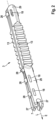
- FIG. 1 a first expansion anchor 1 according to the invention is shown.
- the expansion anchor 1 according to the invention consists of a first anchor sleeve 2 and a second anchor sleeve 3.
- the two anchor sleeves 2, 3 extend together in the longitudinal direction, i.e. along the longitudinal axis L of the expansion anchor 1.
- the anchor sleeves 2, 3 enclose an expansion channel 4, which extends into the Figures 3 and 4 can be seen.
- An expansion element such as a screw or a nail, can be inserted into the expansion channel 4. (not shown) for spreading the expansion anchor 1 through an insertion opening 20 at the rear end 21 of the expansion anchor 1.
- the rear end 21 of the expansion anchor 1 is located, with respect to the longitudinal axis L, opposite the front end 22 of the expansion anchor 1.
- the front end 22 is the end with which the expansion anchor 1 is systematically inserted into a drill hole in an anchoring base (both not shown) in the insertion direction E.
- the first dowel sleeve 2 forms an outer sleeve which Figure 2 encloses the second dowel sleeve 3 shown alone, wherein several openings 23 are provided which completely penetrate the first dowel sleeve 2, such that the second dowel sleeve 3 is visible from the outside and penetrates the first dowel sleeve 2 at least in partial areas.
- several of the openings 23 of the first dowel sleeve 2 are provided with reference symbols by way of example, but not all of them for reasons of clarity.
- the first dowel sleeve 2 comprises a sleeve-like front section 15, which forms the front end 22 of the expansion dowel 1, and a sleeve-like rear section 16, which forms the rear end 21 of the expansion dowel 1. Between these two sections 15, 16, the first dowel sleeve 2 has two expansion legs 5, which are made in one piece with the two sleeve-like sections 15, 16 from polypropylene by injection molding.
- the two expansion legs 5 are connected to one another by several expandable connectors 24, which are U-shaped, so that when they are expanded, i.e. when an expansion element is introduced into the expansion channel 4, they can be expanded by a change in shape in the direction of the circumferential direction.
- connection points of the connectors 24 with the expansion legs 5 move away from each other, with the connectors 24 deforming and lengthening in the circumferential direction.
- two of the U-shaped connectors 24 together form an O-shaped connection between the two expansion legs 5.
- free spaces 25 are formed on the connectors 24, which border on the connectors 24.
- a first free space 7 and a second free space 11 border on a first connector 6.
- the first connector 6 delimits the two free spaces 7, 11 in the longitudinal direction, with the second free space 11 also being delimited in the longitudinal direction by a second connector 8.
- the free spaces 25 are free of the material of the first dowel sleeve 2 and the second dowel sleeve 3 over their entire volume, so that when the expansion dowel 1 is expanded, the connectors 24 which deform during expansion are inserted into the volumes, which the connectors 24 assume in the non-expanded state, can move in unhindered.
- the radial expansion of the volume of the free spaces 25 corresponds to the material thickness of the first expansion sleeve 2 in the respective area adjacent to one of the free spaces 25, that is, a free space 25 completely penetrates the first dowel sleeve 2 in the radial direction and has the same radial expansion as the connector 24 adjacent to the respective free space 25.
- the second dowel sleeve 3 can limit the free spaces 25 in the radial direction towards the inside.
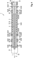
- the first dowel sleeve 2 Adjacent to the first connector 6 and the first free space 7, the first dowel sleeve 2 has an elongated opening 23 which is filled as a penetration 10 with the material of the second dowel sleeve 3.
- a free space 25 is arranged on the side of the first connector 6 facing the penetration 10, as well as on the side of the first connector 6 facing away from the penetration 10, namely here the first free space 7 and the second free space 11.
- the penetration 10 is limited on its side facing away from the first connector 6 by a further connector 24, namely by the third connector 9, to which the third free space 12 and a fourth free space 26 adjoin.
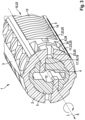
- the second dowel sleeve 3 is in Figure 2 shown alone. It consists of two base bodies 27, which are connected to one another at their end sections 29 by bracket-like connecting elements 28. Two expansion legs 13 of the second dowel sleeve 3 are arranged between the two end sections 29, each of which is connected to the end sections 29 in one piece, independently of one another.
- the second dowel sleeve 3 is also manufactured in one piece using an injection molding process, in the exemplary embodiment from polyamide.
- the second dowel sleeve 3 is injection molded before the first dowel sleeve 2 and then overmolded using a multi-component injection molding process with the material that forms the first dowel sleeve 2, so that the second dowel sleeve 3 is surrounded by the first dowel sleeve 2.
- the end sections 29 of the second dowel sleeve 3 have grooves 18 which are formed during the overmolding of the inner second dowel sleeve 3 during the manufacture of the Expansion dowel 1 is filled with pins 19 in the multi-component injection molding process by the material that forms the first dowel sleeve 2, which are integral components of the first dowel sleeve 2.
- the grooves 18 form with the pins 19 form form-locking elements 17, by means of which the first dowel sleeve 2 is connected in the region of its front section 15 and its rear section 16 in a rotationally and axially fixed manner to the second dowel sleeve 3.
- the expansion legs 5 of the first dowel sleeve 2 and the expansion legs 13 of the second dowel sleeve 3 are not connected to one another, so that they can move freely relative to one another and independently of one another, whereby the expansion legs 5, 13 can adapt optimally to the geometry of the borehole wall in a borehole.
- the second expansion legs 13 have several groove-like weakenings 14 that run in the circumferential direction and are arranged one behind the other in the longitudinal direction. The weakenings 14 locally reduce the thickness of the expansion legs 13 in the radial direction and form predetermined bending and/or buckling points.
- an expansion anchor 1 is created that can be used universally and that can optimally adapt to the geometry of the borehole wall in solid building materials as well as to the shape of a cavity in hollow building materials.
- the free spaces 25 make the expansion anchor 1 according to the invention so flexible that the expansion anchor 1 can adapt its geometry very well to the respective fastening situation, which ensures optimal hold of the expansion anchor 1 in the anchoring base and thus secure fastening of an object to be fastened (not shown).
Landscapes
- Engineering & Computer Science (AREA)
- General Engineering & Computer Science (AREA)
- Mechanical Engineering (AREA)
- Dowels (AREA)
- Joining Of Building Structures In Genera (AREA)
Claims (8)
- Cheville à expansion (1) comportant une première douille de cheville (2) et une seconde douille de cheville (3), lesquelles s'étendent ensemble autour d'un canal d'expansion (4) dans la direction longitudinale (L), dans laquelle un élément d'expansion peut être introduit dans la direction longitudinale dans le canal d'expansion (4) pour l'expansion de la cheville à expansion (1),dans laquelle la première douille de cheville (2) entoure au moins partiellement la seconde douille de cheville (3),et dans laquelle la première douille de cheville (2) présente au moins deux branches d'expansion (5) qui sont reliées entre elles par au moins un connecteur (24) pouvant être élargi de telle sorte que les branches d'expansion (5) peuvent être éloignées l'une de l'autre lors de l'introduction de l'élément d'expansion,dans laquelle un espace libre (25) adjacent au connecteur (24) est formé sur le connecteur (24), dans laquelle une pénétration (10) disposée dans la direction longitudinale entre deux connecteurs (6, 9) est remplie avec le matériau de la seconde douille de cheville (3), caractérisée en ce que le matériau de la seconde douille de cheville (3), matériau avec lequel la pénétration (10) est remplie, forme une branche d'expansion (13) de la seconde douille de cheville (3).
- Cheville à expansion selon la revendication 1, caractérisée en ce que l'espace libre (25) est limité par le connecteur (24) dans la direction longitudinale.
- Cheville à expansion selon l'une des revendications précédentes,
caractérisée en ce que l'espace libre (25) est exempt de matériau de la seconde douille de cheville (3). - Cheville à expansion selon l'une des revendications précédentes,
caractérisée en ce qu'au moins deux connecteurs (6, 8) sont disposés l'un derrière l'autre dans la direction longitudinale, de telle sorte qu'un espace libre (11) est formé au moins entre le premier connecteur (6) et le deuxième connecteur (8). - Cheville à expansion selon la revendication 4, caractérisée en ce qu'au moins trois connecteurs (6, 8, 9) sont disposés les uns derrière les autres dans la direction longitudinale, de telle sorte que le premier espace libre (7) est formé au moins entre le premier connecteur (6) et le deuxième connecteur (8).
- Cheville à expansion selon l'une des revendications précédentes,
caractérisée en ce qu'un espace libre (11, 26) est disposé sur le côté de chaque connecteur (6, 9), lequel côté est opposé à la pénétration (10). - Cheville à expansion selon l'une des revendications précédentes,
caractérisée en ce qu'un espace libre (7, 12) est disposé sur le côté de chaque connecteur (6, 9), lequel côté est orienté vers la pénétration (10). - Cheville à expansion selon l'une des revendications précédentes,
caractérisée en ce que la branche d'expansion (13) présente des affaiblissements (14) locaux.
Applications Claiming Priority (1)
| Application Number | Priority Date | Filing Date | Title |
|---|---|---|---|
| DE102020130796.9A DE102020130796A1 (de) | 2020-11-20 | 2020-11-20 | Spreizdübel |
Publications (3)
| Publication Number | Publication Date |
|---|---|
| EP4008917A1 EP4008917A1 (fr) | 2022-06-08 |
| EP4008917C0 EP4008917C0 (fr) | 2024-10-09 |
| EP4008917B1 true EP4008917B1 (fr) | 2024-10-09 |
Family
ID=78500436
Family Applications (1)
| Application Number | Title | Priority Date | Filing Date |
|---|---|---|---|
| EP21205864.8A Active EP4008917B1 (fr) | 2020-11-20 | 2021-11-02 | Cheville à expansion |
Country Status (2)
| Country | Link |
|---|---|
| EP (1) | EP4008917B1 (fr) |
| DE (1) | DE102020130796A1 (fr) |
Citations (18)
| Publication number | Priority date | Publication date | Assignee | Title |
|---|---|---|---|---|
| DE3301389A1 (de) | 1983-01-18 | 1984-07-19 | Artur Dr.H.C. 7244 Waldachtal Fischer | Spreizduebel |
| DE19742022A1 (de) | 1997-09-24 | 1999-03-25 | Hilti Ag | Spreizdübel |
| EP1178226A2 (fr) | 2000-08-03 | 2002-02-06 | Niemann, Hans Dieter | Elément de connection pour être introduit dans des trous de murs ou similaires |
| WO2002066845A1 (fr) | 2001-02-20 | 2002-08-29 | Turner Intellectual Property Limited | Cheville de fixation |
| EP1135618B1 (fr) | 1998-11-30 | 2002-12-04 | Fischerwerke Arthur Fischer GmbH & Co. KG | Cheville a expansion |
| EP2119920A2 (fr) | 2008-05-14 | 2009-11-18 | ITW CONSTRUCTION PRODUCTS ITALY S.r.l. | Cheville d'expansion |
| DE102012111220A1 (de) | 2012-08-07 | 2014-02-13 | Fischerwerke Gmbh & Co. Kg | Spreizdübel |
| WO2014075776A1 (fr) | 2012-11-14 | 2014-05-22 | Fischerwerke Gmbh & Co. Kg | Cheville expansible |
| DE102013107079A1 (de) | 2013-07-05 | 2015-01-08 | Fischerwerke Gmbh & Co. Kg | Befestigungselement aus Kunststoff |
| DE102013107075A1 (de) | 2013-07-05 | 2015-01-08 | Fischerwerke Gmbh & Co. Kg | Spreizdübel |
| FR3027639A1 (fr) | 2014-10-24 | 2016-04-29 | Ram Chevilles Et Fixations | Cheville a expansion universelle |
| EP2533962B1 (fr) | 2010-02-11 | 2017-05-03 | fischerwerke GmbH & Co. KG | Cheville à expansion |
| WO2019198112A1 (fr) | 2018-04-09 | 2019-10-17 | Friulsider S.P.A. | Goujon à fixation par expansion |
| EP3587839A1 (fr) | 2018-06-29 | 2020-01-01 | Adolf Würth GmbH & Co. KG | Goujon à deux composants pourvu de brides expansibles dentées rendant impossible le glissement |
| EP3587838A1 (fr) | 2018-06-29 | 2020-01-01 | Adolf Würth GmbH & Co. KG | Goujon pourvu de brides expansibles destinées au nouage et de brides expansibles destinées au pliage |
| EP3477126B1 (fr) | 2017-10-31 | 2020-09-09 | Illinois Tool Works, Inc. | Coquille d'expansion |
| EP3851685A1 (fr) | 2020-01-14 | 2021-07-21 | fischerwerke GmbH & Co. KG | Cheville à expansion |
| EP3995706A1 (fr) | 2020-11-07 | 2022-05-11 | fischerwerke GmbH & Co. KG | Cheville à expansion |
Family Cites Families (1)
| Publication number | Priority date | Publication date | Assignee | Title |
|---|---|---|---|---|
| DE102014110737A1 (de) * | 2014-07-29 | 2016-02-04 | Fischerwerke Gmbh & Co. Kg | Spreizdübel |
-
2020
- 2020-11-20 DE DE102020130796.9A patent/DE102020130796A1/de active Pending
-
2021
- 2021-11-02 EP EP21205864.8A patent/EP4008917B1/fr active Active
Patent Citations (19)
| Publication number | Priority date | Publication date | Assignee | Title |
|---|---|---|---|---|
| DE3301389A1 (de) | 1983-01-18 | 1984-07-19 | Artur Dr.H.C. 7244 Waldachtal Fischer | Spreizduebel |
| DE19742022A1 (de) | 1997-09-24 | 1999-03-25 | Hilti Ag | Spreizdübel |
| EP1135618B1 (fr) | 1998-11-30 | 2002-12-04 | Fischerwerke Arthur Fischer GmbH & Co. KG | Cheville a expansion |
| EP1178226A2 (fr) | 2000-08-03 | 2002-02-06 | Niemann, Hans Dieter | Elément de connection pour être introduit dans des trous de murs ou similaires |
| WO2002066845A1 (fr) | 2001-02-20 | 2002-08-29 | Turner Intellectual Property Limited | Cheville de fixation |
| EP2119920A2 (fr) | 2008-05-14 | 2009-11-18 | ITW CONSTRUCTION PRODUCTS ITALY S.r.l. | Cheville d'expansion |
| EP2533962B1 (fr) | 2010-02-11 | 2017-05-03 | fischerwerke GmbH & Co. KG | Cheville à expansion |
| DE102012111220A1 (de) | 2012-08-07 | 2014-02-13 | Fischerwerke Gmbh & Co. Kg | Spreizdübel |
| WO2014075776A1 (fr) | 2012-11-14 | 2014-05-22 | Fischerwerke Gmbh & Co. Kg | Cheville expansible |
| DE102013107079A1 (de) | 2013-07-05 | 2015-01-08 | Fischerwerke Gmbh & Co. Kg | Befestigungselement aus Kunststoff |
| DE102013107075A1 (de) | 2013-07-05 | 2015-01-08 | Fischerwerke Gmbh & Co. Kg | Spreizdübel |
| FR3027639A1 (fr) | 2014-10-24 | 2016-04-29 | Ram Chevilles Et Fixations | Cheville a expansion universelle |
| EP3477126B1 (fr) | 2017-10-31 | 2020-09-09 | Illinois Tool Works, Inc. | Coquille d'expansion |
| WO2019198112A1 (fr) | 2018-04-09 | 2019-10-17 | Friulsider S.P.A. | Goujon à fixation par expansion |
| EP3587839A1 (fr) | 2018-06-29 | 2020-01-01 | Adolf Würth GmbH & Co. KG | Goujon à deux composants pourvu de brides expansibles dentées rendant impossible le glissement |
| EP3587840A1 (fr) | 2018-06-29 | 2020-01-01 | Adolf Würth GmbH & Co. KG | Cheville pourvue de brides expansibles entourées de matrice extensible |
| EP3587838A1 (fr) | 2018-06-29 | 2020-01-01 | Adolf Würth GmbH & Co. KG | Goujon pourvu de brides expansibles destinées au nouage et de brides expansibles destinées au pliage |
| EP3851685A1 (fr) | 2020-01-14 | 2021-07-21 | fischerwerke GmbH & Co. KG | Cheville à expansion |
| EP3995706A1 (fr) | 2020-11-07 | 2022-05-11 | fischerwerke GmbH & Co. KG | Cheville à expansion |
Also Published As
| Publication number | Publication date |
|---|---|
| EP4008917A1 (fr) | 2022-06-08 |
| EP4008917C0 (fr) | 2024-10-09 |
| DE102020130796A1 (de) | 2022-05-25 |
Similar Documents
| Publication | Publication Date | Title |
|---|---|---|
| EP1135618B1 (fr) | Cheville a expansion | |
| DE102011000537A1 (de) | Spreizdübel | |
| EP3175131B1 (fr) | Cheville à expansion | |
| WO2016015823A1 (fr) | Cheville à expansion | |
| WO2016015821A1 (fr) | Cheville à expansion | |
| EP3995706B1 (fr) | Cheville à expansion | |
| EP4008917B1 (fr) | Cheville à expansion | |
| EP1855016B1 (fr) | Cheville | |
| EP0964169B1 (fr) | Cheville pour cadres | |
| DE102023129496A1 (de) | Spreizdübel aus Kunststoff | |
| EP3175129B1 (fr) | Cheville à expansion | |
| DE59703501C5 (de) | Spreizdübel | |
| EP1141559B1 (fr) | Crochet a expansion | |
| WO2009033585A2 (fr) | Cheville pour matériau d'isolation | |
| EP2924302B1 (fr) | Cheville expansible | |
| EP4001675A1 (fr) | Cheville à expansion | |
| EP3173633B1 (fr) | Cheville a expansion | |
| DE202020106135U1 (de) | Dübel und Befestigungssystem | |
| EP4421332B1 (fr) | Cheville à expansion en matière plastique | |
| DE102005034928A1 (de) | Klemmstift | |
| DE4207316A1 (de) | Spreizduebel | |
| EP3670933A1 (fr) | Cheville à expansion | |
| EP0760429A1 (fr) | Cheville d'expansion en matière plastique | |
| DE19753388A1 (de) | Spreizdübel | |
| EP1159537A1 (fr) | Cheville a expansion |
Legal Events
| Date | Code | Title | Description |
|---|---|---|---|
| PUAI | Public reference made under article 153(3) epc to a published international application that has entered the european phase |
Free format text: ORIGINAL CODE: 0009012 |
|
| STAA | Information on the status of an ep patent application or granted ep patent |
Free format text: STATUS: THE APPLICATION HAS BEEN PUBLISHED |
|
| AK | Designated contracting states |
Kind code of ref document: A1 Designated state(s): AL AT BE BG CH CY CZ DE DK EE ES FI FR GB GR HR HU IE IS IT LI LT LU LV MC MK MT NL NO PL PT RO RS SE SI SK SM TR |
|
| STAA | Information on the status of an ep patent application or granted ep patent |
Free format text: STATUS: REQUEST FOR EXAMINATION WAS MADE |
|
| 17P | Request for examination filed |
Effective date: 20221124 |
|
| RBV | Designated contracting states (corrected) |
Designated state(s): AL AT BE BG CH CY CZ DE DK EE ES FI FR GB GR HR HU IE IS IT LI LT LU LV MC MK MT NL NO PL PT RO RS SE SI SK SM TR |
|
| GRAP | Despatch of communication of intention to grant a patent |
Free format text: ORIGINAL CODE: EPIDOSNIGR1 |
|
| STAA | Information on the status of an ep patent application or granted ep patent |
Free format text: STATUS: GRANT OF PATENT IS INTENDED |
|
| RIC1 | Information provided on ipc code assigned before grant |
Ipc: F16B 13/12 20060101AFI20240510BHEP |
|
| INTG | Intention to grant announced |
Effective date: 20240531 |
|
| GRAS | Grant fee paid |
Free format text: ORIGINAL CODE: EPIDOSNIGR3 |
|
| GRAA | (expected) grant |
Free format text: ORIGINAL CODE: 0009210 |
|
| STAA | Information on the status of an ep patent application or granted ep patent |
Free format text: STATUS: THE PATENT HAS BEEN GRANTED |
|
| AK | Designated contracting states |
Kind code of ref document: B1 Designated state(s): AL AT BE BG CH CY CZ DE DK EE ES FI FR GB GR HR HU IE IS IT LI LT LU LV MC MK MT NL NO PL PT RO RS SE SI SK SM TR |
|
| REG | Reference to a national code |
Ref country code: CH Ref legal event code: EP |
|
| REG | Reference to a national code |
Ref country code: DE Ref legal event code: R096 Ref document number: 502021005412 Country of ref document: DE |
|
| REG | Reference to a national code |
Ref country code: IE Ref legal event code: FG4D Free format text: LANGUAGE OF EP DOCUMENT: GERMAN |
|
| U01 | Request for unitary effect filed |
Effective date: 20241009 |
|
| U07 | Unitary effect registered |
Designated state(s): AT BE BG DE DK EE FI FR IT LT LU LV MT NL PT RO SE SI Effective date: 20241015 |
|
| U20 | Renewal fee for the european patent with unitary effect paid |
Year of fee payment: 4 Effective date: 20241021 |
|
| PG25 | Lapsed in a contracting state [announced via postgrant information from national office to epo] |
Ref country code: HR Free format text: LAPSE BECAUSE OF FAILURE TO SUBMIT A TRANSLATION OF THE DESCRIPTION OR TO PAY THE FEE WITHIN THE PRESCRIBED TIME-LIMIT Effective date: 20241009 Ref country code: IS Free format text: LAPSE BECAUSE OF FAILURE TO SUBMIT A TRANSLATION OF THE DESCRIPTION OR TO PAY THE FEE WITHIN THE PRESCRIBED TIME-LIMIT Effective date: 20250209 |
|
| PG25 | Lapsed in a contracting state [announced via postgrant information from national office to epo] |
Ref country code: ES Free format text: LAPSE BECAUSE OF FAILURE TO SUBMIT A TRANSLATION OF THE DESCRIPTION OR TO PAY THE FEE WITHIN THE PRESCRIBED TIME-LIMIT Effective date: 20241009 |
|
| PG25 | Lapsed in a contracting state [announced via postgrant information from national office to epo] |
Ref country code: NO Free format text: LAPSE BECAUSE OF FAILURE TO SUBMIT A TRANSLATION OF THE DESCRIPTION OR TO PAY THE FEE WITHIN THE PRESCRIBED TIME-LIMIT Effective date: 20250109 |
|
| PG25 | Lapsed in a contracting state [announced via postgrant information from national office to epo] |
Ref country code: GR Free format text: LAPSE BECAUSE OF FAILURE TO SUBMIT A TRANSLATION OF THE DESCRIPTION OR TO PAY THE FEE WITHIN THE PRESCRIBED TIME-LIMIT Effective date: 20250110 |
|
| PG25 | Lapsed in a contracting state [announced via postgrant information from national office to epo] |
Ref country code: PL Free format text: LAPSE BECAUSE OF FAILURE TO SUBMIT A TRANSLATION OF THE DESCRIPTION OR TO PAY THE FEE WITHIN THE PRESCRIBED TIME-LIMIT Effective date: 20241009 |
|
| PG25 | Lapsed in a contracting state [announced via postgrant information from national office to epo] |
Ref country code: RS Free format text: LAPSE BECAUSE OF FAILURE TO SUBMIT A TRANSLATION OF THE DESCRIPTION OR TO PAY THE FEE WITHIN THE PRESCRIBED TIME-LIMIT Effective date: 20250109 |
|
| REG | Reference to a national code |
Ref country code: CH Ref legal event code: PL |
|
| PG25 | Lapsed in a contracting state [announced via postgrant information from national office to epo] |
Ref country code: SM Free format text: LAPSE BECAUSE OF FAILURE TO SUBMIT A TRANSLATION OF THE DESCRIPTION OR TO PAY THE FEE WITHIN THE PRESCRIBED TIME-LIMIT Effective date: 20241009 |
|
| PG25 | Lapsed in a contracting state [announced via postgrant information from national office to epo] |
Ref country code: MC Free format text: LAPSE BECAUSE OF FAILURE TO SUBMIT A TRANSLATION OF THE DESCRIPTION OR TO PAY THE FEE WITHIN THE PRESCRIBED TIME-LIMIT Effective date: 20241009 |
|
| REG | Reference to a national code |
Ref country code: CH Ref legal event code: PL |
|
| PLBI | Opposition filed |
Free format text: ORIGINAL CODE: 0009260 |
|
| PG25 | Lapsed in a contracting state [announced via postgrant information from national office to epo] |
Ref country code: CH Free format text: LAPSE BECAUSE OF NON-PAYMENT OF DUE FEES Effective date: 20241130 |
|
| PLAX | Notice of opposition and request to file observation + time limit sent |
Free format text: ORIGINAL CODE: EPIDOSNOBS2 |
|
| PG25 | Lapsed in a contracting state [announced via postgrant information from national office to epo] |
Ref country code: SK Free format text: LAPSE BECAUSE OF FAILURE TO SUBMIT A TRANSLATION OF THE DESCRIPTION OR TO PAY THE FEE WITHIN THE PRESCRIBED TIME-LIMIT Effective date: 20241009 |
|
| PG25 | Lapsed in a contracting state [announced via postgrant information from national office to epo] |
Ref country code: CZ Free format text: LAPSE BECAUSE OF FAILURE TO SUBMIT A TRANSLATION OF THE DESCRIPTION OR TO PAY THE FEE WITHIN THE PRESCRIBED TIME-LIMIT Effective date: 20241009 |
|
| 26 | Opposition filed |
Opponent name: ADOLF WUERTH GMBH & CO. KG Effective date: 20250708 |
|
| PG25 | Lapsed in a contracting state [announced via postgrant information from national office to epo] |
Ref country code: IE Free format text: LAPSE BECAUSE OF NON-PAYMENT OF DUE FEES Effective date: 20241102 |
|
| U20 | Renewal fee for the european patent with unitary effect paid |
Year of fee payment: 5 Effective date: 20250923 |
|
| PLBB | Reply of patent proprietor to notice(s) of opposition received |
Free format text: ORIGINAL CODE: EPIDOSNOBS3 |