EP4008917B1 - Expansion anchor - Google Patents
Expansion anchor Download PDFInfo
- Publication number
- EP4008917B1 EP4008917B1 EP21205864.8A EP21205864A EP4008917B1 EP 4008917 B1 EP4008917 B1 EP 4008917B1 EP 21205864 A EP21205864 A EP 21205864A EP 4008917 B1 EP4008917 B1 EP 4008917B1
- Authority
- EP
- European Patent Office
- Prior art keywords
- expansion
- connector
- dowel sleeve
- dowel
- sleeve
- Prior art date
- Legal status (The legal status is an assumption and is not a legal conclusion. Google has not performed a legal analysis and makes no representation as to the accuracy of the status listed.)
- Active
Links
Images

Classifications
-
- F—MECHANICAL ENGINEERING; LIGHTING; HEATING; WEAPONS; BLASTING
- F16—ENGINEERING ELEMENTS AND UNITS; GENERAL MEASURES FOR PRODUCING AND MAINTAINING EFFECTIVE FUNCTIONING OF MACHINES OR INSTALLATIONS; THERMAL INSULATION IN GENERAL
- F16B—DEVICES FOR FASTENING OR SECURING CONSTRUCTIONAL ELEMENTS OR MACHINE PARTS TOGETHER, e.g. NAILS, BOLTS, CIRCLIPS, CLAMPS, CLIPS OR WEDGES; JOINTS OR JOINTING
- F16B13/00—Dowels or other devices fastened in walls or the like by inserting them in holes made therein for that purpose
- F16B13/12—Separate metal or non-separate or non-metal dowel sleeves fastened by inserting the screw, nail or the like
- F16B13/124—Separate metal or non-separate or non-metal dowel sleeves fastened by inserting the screw, nail or the like fastened by inserting a threaded element, e.g. screw or bolt
Definitions
- the invention relates to an expansion anchor with the features of the preamble of claim 1.
- the known expansion dowels each comprise two dowel sleeves made from different plastic components.
- One of the dowel sleeves has two expansion legs that are connected to one another by expandable connectors.
- the connectors are V-shaped or have straight, diagonal ribs that are spaced apart from one another in the longitudinal direction, so that volumes are created between them that are filled by the plastic component of the other dowel sleeve, which, due to the additional material between the connectors, increases the expansion pressure against the wall of a drill hole in a solid building material, such as concrete, and thus enables large holding forces.
- Another expansion anchor is from the DE 10 2013 107075 A1 known.
- the object of the invention is to create an expansion anchor which can be used universally and which enables reliable anchoring with a high holding force both in a solid building material, such as concrete, and in hollow building materials, such as plasterboard or perforated bricks.
- the expansion dowel comprises a first dowel sleeve and a second dowel sleeve.
- the two dowel sleeves extend together in the longitudinal direction around an expansion channel into which an expansion element, for example a screw or a nail, can be inserted for the systematic expansion of the expansion dowel.
- the two dowel sleeves consist in particular of different plastics, which differ, for example, in terms of their colors and/or hardness.
- one of the dowel sleeves can be made of polyamide and the other dowel sleeve of polypropylene.
- the expansion dowel is manufactured from two different plastics using a two-component injection molding process.
- the two dowel sleeves are arranged in such a way that the first dowel sleeve at least partially encloses the second dowel sleeve, in particular in a front and/or a rear sleeve-like section of the expansion dowel in the circumferential direction.
- “Enclosing” here does not just mean that the inner second dowel sleeve is completely covered by the material of the first dowel sleeve; the first dowel sleeve can also have openings, for example, through which parts of the second dowel sleeve are visible through the first dowel sleeve and/or can pass through to the outside.
- the second expansion sleeve is therefore at least locally located within the first expansion sleeve.
- “Front” and “rear” here and below refer to the direction in which the expansion dowel is planned to be inserted into a drill hole.
- the front end of the expansion dowel is inserted into the drill hole first.
- the two dowel sleeves are connected to one another axially and/or rotationally fixedly, at least locally, in particular in the front and/or rear sections, in particular in a form-fitting manner, in particular by means of a groove-tenon connection as a form-fitting element.
- the first dowel sleeve has at least two expansion legs.
- the expansion legs extend in particular in the longitudinal direction parallel to the expansion channel and are mounted in particular at their front and/or rear end on a sleeve-like section and connected to one another by this.
- the two expansion legs are connected to one another by at least one expandable connector in such a way that the expansion legs can be moved away from one another when the expansion element is inserted, so that the expansion dowel expands in the area of the expansion legs, i.e. increases its diameter.
- the expansion takes place in particular radially to the longitudinal axis of the expansion dowel, which runs parallel to, in particular in the middle of, the expansion channel.
- Diameter here means the diameter of a cylinder that circumscribes the two expansion legs and is rotationally symmetrical to the longitudinal axis of the expansion dowel.
- Expandable means that the connector can increase its length in the circumferential direction when expanding, for example by changing its shape and/or by stretching the material.
- the connector is inclined and/or U- or V-shaped in an unexpanded state, as is known from the prior art.
- it is made of the material of the first dowel sleeve and is made in one piece with it.
- a free space adjacent to the connector is formed on the connector.
- free space is meant a volume that extends in the longitudinal and circumferential direction and in which no or only a small amount of material from one or both dowel sleeves is arranged, such that the connector can move into the free space when the expansion dowel is expanded, i.e. can be moved into the free space when expanded.
- the movement of the connector occurs in particular in the longitudinal direction when expanded, and in particular also radially outwards.
- the first dowel sleeve has an opening adjacent to the connector as a free space, which completely penetrates the wall of the first dowel sleeve in the radial direction, which means that the free space has the same radial extent as the connector adjacent to the respective free space.
- the opening in the movement area of the connector can be completely or partially closed only by a thin injection-molded skin, the wall thickness of which is a maximum of 10%, in particular a maximum of 5% of the wall thickness of the connector.
- the design of the expansion anchor according to the invention has the advantage that the mobility of the connector is not hindered or negatively influenced by the material of the first or second anchor sleeve.
- the two expansion legs of the first anchor sleeve can therefore expand freely in a building material, for example in the area behind a plasterboard, so that the expansion behavior and thus the load-bearing capacity of the expansion anchor is improved compared to the expansion anchors known from the prior art.
- the free space in the radial direction towards the longitudinal axis is at least partially limited by the second dowel sleeve.
- the free space is limited in the longitudinal direction by the connector.
- This means that an opening forming the free space is directly adjacent to the connector, which limits the opening in the longitudinal direction on one side.
- the side of the opening opposite the connector is limited by material from the first and/or the second dowel sleeve. Due to this special design, the connector can move freely into the volume when expanding, which forms the free space or the opening in the unexpanded state, without the connector being hindered by material that would be arranged between the connector and the opening.
- the height of the free space therefore corresponds to the wall thickness of the connector and the other parts of the first dowel sleeve that limit the free space in the longitudinal and circumferential directions.
- At least two connectors are arranged one behind the other in the longitudinal direction, such that the free space is formed at least between the first connector and the second connector.
- the two connectors limit the free space in the longitudinal direction.
- At least three connectors are arranged one behind the other in the longitudinal direction such that a first free space is formed at least between the first connector and the second connector.
- the expansion dowel has at least two connectors and that a penetration arranged in the longitudinal direction between the connectors is at least partially filled with the material of the second dowel sleeve.
- This material of the second dowel sleeve preferably forms an expansion leg of the second dowel sleeve, which can also be expanded outwards when the expansion element is introduced into the expansion channel through the first dowel sleeve.
- the expansion leg of the second dowel sleeve can adapt well to the wall of the drill hole in a solid building material or can easily buckle and/or knot in a cavity
- the expansion leg preferably has local weakenings, in particular in the form of grooves, which run in particular in the circumferential direction and act as predetermined buckling and/or bending points.
- the local weakenings are arranged one behind the other in the longitudinal direction, in particular as grooves running parallel to one another.
- a free space is arranged on the side facing away from the penetration and/or on the side facing the penetration of each of the connectors delimiting the penetration, such that the connectors can move longitudinally into the free spaces when spreading, which gives the second spreading legs improved mobility when spreading.
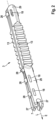
- FIG. 1 a first expansion anchor 1 according to the invention is shown.
- the expansion anchor 1 according to the invention consists of a first anchor sleeve 2 and a second anchor sleeve 3.
- the two anchor sleeves 2, 3 extend together in the longitudinal direction, i.e. along the longitudinal axis L of the expansion anchor 1.
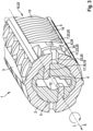
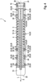
- the anchor sleeves 2, 3 enclose an expansion channel 4, which extends into the Figures 3 and 4 can be seen.
- An expansion element such as a screw or a nail, can be inserted into the expansion channel 4. (not shown) for spreading the expansion anchor 1 through an insertion opening 20 at the rear end 21 of the expansion anchor 1.
- the rear end 21 of the expansion anchor 1 is located, with respect to the longitudinal axis L, opposite the front end 22 of the expansion anchor 1.
- the front end 22 is the end with which the expansion anchor 1 is systematically inserted into a drill hole in an anchoring base (both not shown) in the insertion direction E.
- the first dowel sleeve 2 forms an outer sleeve which Figure 2 encloses the second dowel sleeve 3 shown alone, wherein several openings 23 are provided which completely penetrate the first dowel sleeve 2, such that the second dowel sleeve 3 is visible from the outside and penetrates the first dowel sleeve 2 at least in partial areas.
- several of the openings 23 of the first dowel sleeve 2 are provided with reference symbols by way of example, but not all of them for reasons of clarity.
- the first dowel sleeve 2 comprises a sleeve-like front section 15, which forms the front end 22 of the expansion dowel 1, and a sleeve-like rear section 16, which forms the rear end 21 of the expansion dowel 1. Between these two sections 15, 16, the first dowel sleeve 2 has two expansion legs 5, which are made in one piece with the two sleeve-like sections 15, 16 from polypropylene by injection molding.
- the two expansion legs 5 are connected to one another by several expandable connectors 24, which are U-shaped, so that when they are expanded, i.e. when an expansion element is introduced into the expansion channel 4, they can be expanded by a change in shape in the direction of the circumferential direction.
- connection points of the connectors 24 with the expansion legs 5 move away from each other, with the connectors 24 deforming and lengthening in the circumferential direction.
- two of the U-shaped connectors 24 together form an O-shaped connection between the two expansion legs 5.
- free spaces 25 are formed on the connectors 24, which border on the connectors 24.
- a first free space 7 and a second free space 11 border on a first connector 6.
- the first connector 6 delimits the two free spaces 7, 11 in the longitudinal direction, with the second free space 11 also being delimited in the longitudinal direction by a second connector 8.
- the free spaces 25 are free of the material of the first dowel sleeve 2 and the second dowel sleeve 3 over their entire volume, so that when the expansion dowel 1 is expanded, the connectors 24 which deform during expansion are inserted into the volumes, which the connectors 24 assume in the non-expanded state, can move in unhindered.
- the radial expansion of the volume of the free spaces 25 corresponds to the material thickness of the first expansion sleeve 2 in the respective area adjacent to one of the free spaces 25, that is, a free space 25 completely penetrates the first dowel sleeve 2 in the radial direction and has the same radial expansion as the connector 24 adjacent to the respective free space 25.
- the second dowel sleeve 3 can limit the free spaces 25 in the radial direction towards the inside.
- the first dowel sleeve 2 Adjacent to the first connector 6 and the first free space 7, the first dowel sleeve 2 has an elongated opening 23 which is filled as a penetration 10 with the material of the second dowel sleeve 3.
- a free space 25 is arranged on the side of the first connector 6 facing the penetration 10, as well as on the side of the first connector 6 facing away from the penetration 10, namely here the first free space 7 and the second free space 11.
- the penetration 10 is limited on its side facing away from the first connector 6 by a further connector 24, namely by the third connector 9, to which the third free space 12 and a fourth free space 26 adjoin.
- the second dowel sleeve 3 is in Figure 2 shown alone. It consists of two base bodies 27, which are connected to one another at their end sections 29 by bracket-like connecting elements 28. Two expansion legs 13 of the second dowel sleeve 3 are arranged between the two end sections 29, each of which is connected to the end sections 29 in one piece, independently of one another.
- the second dowel sleeve 3 is also manufactured in one piece using an injection molding process, in the exemplary embodiment from polyamide.
- the second dowel sleeve 3 is injection molded before the first dowel sleeve 2 and then overmolded using a multi-component injection molding process with the material that forms the first dowel sleeve 2, so that the second dowel sleeve 3 is surrounded by the first dowel sleeve 2.
- the end sections 29 of the second dowel sleeve 3 have grooves 18 which are formed during the overmolding of the inner second dowel sleeve 3 during the manufacture of the Expansion dowel 1 is filled with pins 19 in the multi-component injection molding process by the material that forms the first dowel sleeve 2, which are integral components of the first dowel sleeve 2.
- the grooves 18 form with the pins 19 form form-locking elements 17, by means of which the first dowel sleeve 2 is connected in the region of its front section 15 and its rear section 16 in a rotationally and axially fixed manner to the second dowel sleeve 3.
- the expansion legs 5 of the first dowel sleeve 2 and the expansion legs 13 of the second dowel sleeve 3 are not connected to one another, so that they can move freely relative to one another and independently of one another, whereby the expansion legs 5, 13 can adapt optimally to the geometry of the borehole wall in a borehole.
- the second expansion legs 13 have several groove-like weakenings 14 that run in the circumferential direction and are arranged one behind the other in the longitudinal direction. The weakenings 14 locally reduce the thickness of the expansion legs 13 in the radial direction and form predetermined bending and/or buckling points.
- an expansion anchor 1 is created that can be used universally and that can optimally adapt to the geometry of the borehole wall in solid building materials as well as to the shape of a cavity in hollow building materials.
- the free spaces 25 make the expansion anchor 1 according to the invention so flexible that the expansion anchor 1 can adapt its geometry very well to the respective fastening situation, which ensures optimal hold of the expansion anchor 1 in the anchoring base and thus secure fastening of an object to be fastened (not shown).
Landscapes
- Engineering & Computer Science (AREA)
- General Engineering & Computer Science (AREA)
- Mechanical Engineering (AREA)
- Dowels (AREA)
- Joining Of Building Structures In Genera (AREA)
Description
Die Erfindung betrifft einen Spreizdübel mit den Merkmalen des Oberbegriffs des Anspruchs 1.The invention relates to an expansion anchor with the features of the preamble of claim 1.
Aus der Offenlegungsschrift
Ein weiterer Spreizdübel ist aus der
Aufgabe der Erfindung ist es, einen Spreizdübel zu schaffen, der universell einsetzbar ist und sowohl in einem Vollbaustoff, wie beispielsweise Beton, als auch in Hohlbaustoffen, wie beispielsweise Gipskartonplatten oder Lochziegel, eine zuverlässige Verankerung mit hoher Haltekraft ermöglicht.The object of the invention is to create an expansion anchor which can be used universally and which enables reliable anchoring with a high holding force both in a solid building material, such as concrete, and in hollow building materials, such as plasterboard or perforated bricks.
Diese Aufgabe wird erfindungsgemäß durch einen Spreizdübel mit den Merkmalen des Anspruchs 1 gelöst. Der erfindungsgemäße Spreizdübel umfasst eine erste Dübelhülse und eine zweite Dübelhülse. Die beiden Dübelhülsen erstrecken sich gemeinsam in Längsrichtung um einen Spreizkanal, in den zum planmäßigen Aufspreizen des Spreizdübels ein Spreizelement, beispielsweise eine Schraube oder ein Nagel, einführbar ist. Die beiden Dübelhülsen bestehen insbesondere aus unterschiedlichen Kunststoffen, die sich beispielsweise hinsichtlich ihrer Farben und/oder Härten unterscheiden. So kann beispielsweise eine der Dübelhülsen aus Polyamid und die andere Dübelhülse aus Polypropylen hergestellt sein. Insbesondere ist der Spreizdübel im Zweikomponentenspritzgussverfahren aus zwei unterschiedlichen Kunststoffen hergestellt. Die beiden Dübelhülsen sind derart angeordnet, dass die erste Dübelhülse die zweite Dübelhülse zumindest teilweise umschließt, insbesondere in einem vorderen und/oder einem hinteren hülsenartigen Abschnitt des Spreizdübels in Umfangsrichtung. "Umschließen" meint hier nicht nur ein vollflächiges Abdecken der innen liegenden zweiten Dübelhülse durch das Material der ersten Dübelhülse, die erste Dübelhülse kann beispielsweise auch Durchbrechungen aufweisen, durch die Teile der zweiten Dübelhülse durch die erste Dübelhülse sichtbar sind und/oder nach außen durchtreten können. Somit liegt die zweite Spreizhülse zumindest lokal innerhalb der ersten Spreizhülse. "Vorne" und "hinten" beziehen sich hier und nachfolgend auf die Richtung, in der der Spreizdübel planmäßig in ein Bohrloch eingebracht wird. Dabei wird das vordere Ende des Spreizdübels zuerst in das Bohrloch eingeführt. Insbesondere sind die beiden Dübelhülsen zumindest lokal, insbesondere in dem vorderen und/oder dem hinteren Abschnitt axial und/oder drehfest miteinander verbunden, insbesondere formschlüssig, insbesondere mittels einer Nut-Zapfen-Verbindung als Formschlusselement.This object is achieved according to the invention by an expansion dowel with the features of claim 1. The expansion dowel according to the invention comprises a first dowel sleeve and a second dowel sleeve. The two dowel sleeves extend together in the longitudinal direction around an expansion channel into which an expansion element, for example a screw or a nail, can be inserted for the systematic expansion of the expansion dowel. The two dowel sleeves consist in particular of different plastics, which differ, for example, in terms of their colors and/or hardness. For example, one of the dowel sleeves can be made of polyamide and the other dowel sleeve of polypropylene. In particular, the expansion dowel is manufactured from two different plastics using a two-component injection molding process. The two dowel sleeves are arranged in such a way that the first dowel sleeve at least partially encloses the second dowel sleeve, in particular in a front and/or a rear sleeve-like section of the expansion dowel in the circumferential direction. "Enclosing" here does not just mean that the inner second dowel sleeve is completely covered by the material of the first dowel sleeve; the first dowel sleeve can also have openings, for example, through which parts of the second dowel sleeve are visible through the first dowel sleeve and/or can pass through to the outside. The second expansion sleeve is therefore at least locally located within the first expansion sleeve. "Front" and "rear" here and below refer to the direction in which the expansion dowel is planned to be inserted into a drill hole. The front end of the expansion dowel is inserted into the drill hole first. In particular, the two dowel sleeves are connected to one another axially and/or rotationally fixedly, at least locally, in particular in the front and/or rear sections, in particular in a form-fitting manner, in particular by means of a groove-tenon connection as a form-fitting element.
Zur Verankerung in einem Bohrloch weist die erste Dübelhülse mindestens zwei Spreizschenkel auf. Die Spreizschenkel erstrecken sich insbesondere in Längsrichtung parallel zum Spreizkanal und sind insbesondere an ihrem vorderen und/oder hinterem Ende an einem hülsenartigen Abschnitt gelagert und durch diesen miteinander verbunden. Die beiden Spreizschenkel sind durch mindestens einen aufweitbaren Verbinder miteinander verbunden, derart, dass die Spreizschenkel beim Einbringen des Spreizelements voneinander weg bewegbar sind, sodass der Spreizdübel im Bereich der Spreizschenkel aufspreizt, also seinen Durchmesser vergrößert. Das Aufspreizen erfolgt insbesondere radial zur Längsachse des Spreizdübels, die parallel zum, insbesondere mittig im, Spreizkanal verläuft. Mit "Durchmesser" ist hier der Durchmesser eines der beiden Spreizschenkel umschreibenden Zylinders gemeint, der rotationssymmetrisch zur Längsachse des Spreizdübels ist. "Aufweitbar" meint, dass der Verbinder beim Aufspreizen seine Länge in Umfangsrichtung vergrößern kann, beispielsweise durch eine Formänderung und oder durch eine Materialdehnung. Insbesondere ist der Verbinder in einem unverspreizten Zustand schräggestellt und/oder U- oder V-förmig, wie dies aus dem Stand der Technik bekannt ist. Insbesondere ist er aus dem Material der ersten Dübelhülse und mit dieser einstückig hergestellt.For anchoring in a drill hole, the first dowel sleeve has at least two expansion legs. The expansion legs extend in particular in the longitudinal direction parallel to the expansion channel and are mounted in particular at their front and/or rear end on a sleeve-like section and connected to one another by this. The two expansion legs are connected to one another by at least one expandable connector in such a way that the expansion legs can be moved away from one another when the expansion element is inserted, so that the expansion dowel expands in the area of the expansion legs, i.e. increases its diameter. The expansion takes place in particular radially to the longitudinal axis of the expansion dowel, which runs parallel to, in particular in the middle of, the expansion channel. "Diameter" here means the diameter of a cylinder that circumscribes the two expansion legs and is rotationally symmetrical to the longitudinal axis of the expansion dowel. "Expandable" means that the connector can increase its length in the circumferential direction when expanding, for example by changing its shape and/or by stretching the material. In particular, the connector is inclined and/or U- or V-shaped in an unexpanded state, as is known from the prior art. In particular, it is made of the material of the first dowel sleeve and is made in one piece with it.
Erfindungsgemäß ist an dem Verbinder ein an den Verbinder angrenzender Freiraum ausgebildet. Mit "Freiraum" ist ein Volumen gemeint, das sich in Längs- und in Umfangsrichtung erstreckt und in dem kein oder nur wenig Material von einer der oder von beiden Dübelhülsen angeordnet ist, derart, dass der Verbinder sich beim Verspreizen des Spreizdübels in den Freiraum hinein bewegen kann, also beim Verspreizen in den Freiraum hinein bewegbar ist. Die Bewegung des Verbinders erfolgt beim Aufspreizen insbesondere in Längsrichtung, insbesondere zudem radial nach außen. Insbesondere weist die erste Dübelhülse eine an den Verbinder grenzende Öffnung als Freiraum auf, die die Wand der ersten Dübelhülse in radialer Richtung vollständig durchdringt, was bedeutet, dass der Freiraum die gleiche radiale Ausdehnung aufweist, wie der an den jeweiligen Freiraum angrenzenden Verbinder. Alternativ kann die Öffnung im Bewegungsbereich des Verbinders nur durch eine dünne Spritzhaut, deren Wandstärke maximal 10 %, insbesondere maximal 5 % der Wandstärke des Verbinders beträgt, ganz oder teilweise verschlossen sein.According to the invention, a free space adjacent to the connector is formed on the connector. By "free space" is meant a volume that extends in the longitudinal and circumferential direction and in which no or only a small amount of material from one or both dowel sleeves is arranged, such that the connector can move into the free space when the expansion dowel is expanded, i.e. can be moved into the free space when expanded. The movement of the connector occurs in particular in the longitudinal direction when expanded, and in particular also radially outwards. In particular, the first dowel sleeve has an opening adjacent to the connector as a free space, which completely penetrates the wall of the first dowel sleeve in the radial direction, which means that the free space has the same radial extent as the connector adjacent to the respective free space. Alternatively, the opening in the movement area of the connector can be completely or partially closed only by a thin injection-molded skin, the wall thickness of which is a maximum of 10%, in particular a maximum of 5% of the wall thickness of the connector.
Die erfindungsgemäße Ausbildung des Spreizdübels hat den Vorteil, dass die Beweglichkeit des Verbinders nicht durch Material der ersten oder der zweiten Dübelhülse erschwert oder negativ beeinflusst wird. Die beiden Spreizschenkel der ersten Dübelhülse können dadurch in einem Baustoff, beispielsweise im Bereich hinter einer Gipskartonplatte, ungehindert aufspreizen, sodass das Spreizverhalten und damit die Tragfähigkeit des Spreizdübels gegenüber den aus dem Stand der Technik bekannten Spreizdübeln verbessert ist.The design of the expansion anchor according to the invention has the advantage that the mobility of the connector is not hindered or negatively influenced by the material of the first or second anchor sleeve. The two expansion legs of the first anchor sleeve can therefore expand freely in a building material, for example in the area behind a plasterboard, so that the expansion behavior and thus the load-bearing capacity of the expansion anchor is improved compared to the expansion anchors known from the prior art.
Insbesondere wird der Freiraum in radialer Richtung zur Längsachse hin zumindest teilweise durch die zweite Dübelhülse begrenzt.In particular, the free space in the radial direction towards the longitudinal axis is at least partially limited by the second dowel sleeve.
Vorzugsweise wird der Freiraum in Längsrichtung durch den Verbinder begrenzt. Das heißt, dass eine den Freiraum bildende Öffnung direkt an den Verbinder grenzt, der die Öffnung in Längsrichtung zu einer Seite begrenzt. Die dem Verbinder gegenüberliegende Seite der Öffnung ist durch Material der ersten und/oder der zweiten Dübelhülse begrenzt. Der Verbinder kann sich aufgrund dieser speziellen Ausbildung beim Aufspreizen frei in das Volumen hinein bewegen, das im unverspreizten Zustand den Freiraum beziehungsweise die Öffnung bildet, ohne dass der Verbinder durch Material, das zwischen dem Verbinder und der Öffnung angeordnet wäre, behindert wird.Preferably, the free space is limited in the longitudinal direction by the connector. This means that an opening forming the free space is directly adjacent to the connector, which limits the opening in the longitudinal direction on one side. The side of the opening opposite the connector is limited by material from the first and/or the second dowel sleeve. Due to this special design, the connector can move freely into the volume when expanding, which forms the free space or the opening in the unexpanded state, without the connector being hindered by material that would be arranged between the connector and the opening.
Vorzugsweise befindet sich im Freiraum kein Material der zweiten Dübelhülse, das heißt, dass der gesamte Freiraum über die gesamte Wandstärke der ersten Dübelhülse frei vom Material der zweiten Dübelhülse ist. Die Höhe des Freiraums entspricht somit der Wandstärke des Verbinders und der anderen Teile der ersten Dübelhülse, die den Freiraum in Längs- und Umfangsrichtung begrenzen.Preferably, there is no material of the second dowel sleeve in the free space, which means that the entire free space over the entire wall thickness of the first dowel sleeve is free of material of the second dowel sleeve. The height of the free space therefore corresponds to the wall thickness of the connector and the other parts of the first dowel sleeve that limit the free space in the longitudinal and circumferential directions.
Weiterhin ist bevorzugt, dass mindestens zwei Verbinder in Längsrichtung hintereinander angeordnet sind, derart, dass zumindest zwischen dem ersten Verbinder und dem zweiten Verbinder der Freiraum ausgebildet ist. Insbesondere begrenzen die beiden Verbinder den Freiraum in Längsrichtung.It is further preferred that at least two connectors are arranged one behind the other in the longitudinal direction, such that the free space is formed at least between the first connector and the second connector. In particular, the two connectors limit the free space in the longitudinal direction.
Vorzugsweise sind mindestens drei Verbinder in Längsrichtung hintereinander angeordnet, derart, dass zumindest zwischen dem ersten Verbinder und dem zweiten Verbinder ein erster Freiraum ausgebildet ist.Preferably, at least three connectors are arranged one behind the other in the longitudinal direction such that a first free space is formed at least between the first connector and the second connector.
Weiterhin ist bevorzugt, dass der Spreizdübel mindestens zwei Verbinder aufweist und dass eine in Längsrichtung zwischen den Verbindern angeordnete Durchdringung mit dem Material der zweiten Dübelhülse zumindest teilweise gefüllt ist. Dieses Material der zweiten Dübelhülse bildet vorzugsweise einen Spreizschenkel der zweiten Dübelhülse aus, der beim Einbringen des Spreizelements in den Spreizkanal durch die erste Dübelhülse hindurch ebenfalls nach außen aufspreizbar ist.It is further preferred that the expansion dowel has at least two connectors and that a penetration arranged in the longitudinal direction between the connectors is at least partially filled with the material of the second dowel sleeve. This material of the second dowel sleeve preferably forms an expansion leg of the second dowel sleeve, which can also be expanded outwards when the expansion element is introduced into the expansion channel through the first dowel sleeve.
Damit sich der Spreizschenkel der zweiten Dübelhülse in einem Vollbaustoff gut an die Wand des Bohrlochs anpassen oder bei einem Hohlraum leicht ausknicken und/oder verknoten kann, weist der Spreizschenkel vorzugsweise lokale Schwächungen, insbesondere in Form von Nuten auf, die insbesondere in Umfangsrichtung verlaufen und als Sollknick- und/oder Sollbiegestellen wirken. Insbesondere sind die lokalen Schwächungen in Längsrichtung hintereinander angeordnet, insbesondere als zueinander parallel verlaufende Nuten.So that the expansion leg of the second dowel sleeve can adapt well to the wall of the drill hole in a solid building material or can easily buckle and/or knot in a cavity, the expansion leg preferably has local weakenings, in particular in the form of grooves, which run in particular in the circumferential direction and act as predetermined buckling and/or bending points. In particular, the local weakenings are arranged one behind the other in the longitudinal direction, in particular as grooves running parallel to one another.
Damit das Aufspreizen des Spreizschenkels der zweiten Dübelhülse das Aufspreizen der Spreizschenkel der ersten Dübelhülse nicht behindert, ist auf der der Durchdringung abgewandten Seite und/oder auf der der Durchdringung zugewandten Seite eines jeden der die Durchdringung begrenzenden Verbinders ein Freiraum angeordnet, derart, dass die Verbinder sich in Längsrichtung beim Verspreizen in die Freiräume bewegen können, wodurch die zweiten Spreizschenkel beim Aufspreizen eine verbesserte Beweglichkeit aufweisen.In order that the spreading of the expansion leg of the second dowel sleeve does not hinder the spreading of the expansion legs of the first dowel sleeve, a free space is arranged on the side facing away from the penetration and/or on the side facing the penetration of each of the connectors delimiting the penetration, such that the connectors can move longitudinally into the free spaces when spreading, which gives the second spreading legs improved mobility when spreading.
Die vorstehend in der Beschreibung genannten Merkmale und Merkmalskombinationen, Ausführungen und Ausgestaltungen der Erfindung, sowie die nachfolgend in der Figurenbeschreibung genannten und/oder in einer Figur gezeichneten Merkmale und Merkmalskombinationen sind nicht nur in der jeweils angegebenen oder gezeichneten Kombination, sondern auch in grundsätzlich beliebigen anderen Kombinationen oder aber einzeln verwendbar. Es sind Ausführungen der Erfindung möglich, die nicht alle Merkmale eines abhängigen Anspruchs aufweisen. Auch können einzelne Merkmale eines Anspruchs durch andere offenbarte Merkmale oder Merkmalskombinationen ersetzt werden. Ausführungen der Erfindung, die nicht alle Merkmale des Ausführungsbeispiels aufweisen, sind ebenfalls möglich.The features and combinations of features, embodiments and configurations of the invention mentioned above in the description, as well as the features and combinations of features mentioned below in the description of the figures and/or drawn in a figure can be used not only in the combination specified or drawn in each case, but also in any other combination or individually. Embodiments of the invention are possible that do not have all the features of a dependent claim. Individual features of a claim can also be replaced by other disclosed features or combinations of features. Embodiments of the invention that do not have all the features of the exemplary embodiment are also possible.
Die Erfindung wird nachfolgend anhand eines Ausführungsbeispiels näher erläutert.The invention is explained in more detail below using an embodiment.
Es zeigen:
- Figur 1
- einen ersten erfindungsgemäßen Spreizdübel in einer perspektivischen Ansicht;
Figur 2- eine zweite Dübelhülse des erfindungsgemäßen Spreizdübels in einer perspektivischen Ansicht;
Figur 3- einen Querschnitt durch den ersten Spreizdübel in der Ebene III der
Figur 1 in einer perspektivischen Ansicht; und Figur 4- einen Längsschnitt durch den erfindungsgemäßen Spreizdübel in der Ebene IV der
Figur 1 .
- Figure 1
- a first expansion anchor according to the invention in a perspective view;
- Figure 2
- a second dowel sleeve of the expansion dowel according to the invention in a perspective view;
- Figure 3
- a cross-section through the first expansion anchor in level III of the
Figure 1 in a perspective view; and - Figure 4
- a longitudinal section through the expansion anchor according to the invention in plane IV of the
Figure 1 .
In
Im Ausführungsbeispiel der
Die erste Dübelhülse 2 umfasst einen hülsenartigen vorderen Abschnitt 15, der das vordere Ende 22 des Spreizdübels 1 bildet, sowie einen hülsenartigen hinteren Abschnitt 16, der das hintere Ende 21 des Spreizdübels 1 bildet. Zwischen diesen beiden Abschnitten 15, 16 weist die erste Dübelhülse 2 zwei Spreizschenkel 5 auf, die einstückig mit den beiden hülsenartigen Abschnitten 15, 16 aus Polypropylen durch Spritzgießen hergestellt sind. Die beiden Spreizschenkel 5 sind durch mehrere aufweitbare Verbinder 24 miteinander verbunden, die U-förmig ausgebildet sind, sodass sie beim Aufspreizen, also dann, wenn ein Spreizelement in den Spreizkanal 4 eingebracht wird, durch eine Formänderung in Richtung der Umfangsrichtung aufweitbar sind. Das bedeutet, dass sich beim Aufspreizen die Verbindungsstellen der Verbinder 24 mit den Spreizschenkeln 5 voneinander wegbewegen, wobei die Verbinder 24 sich verformen und in Umfangsrichtung längen. Teilweise bilden zwei der U-förmigen Verbinder 24 gemeinsam eine O-förmige Verbindung zwischen den beiden Spreizschenkeln 5 aus. Um das Spreizverhalten des Spreizdübels 1 zu verbessern, sind an den Verbindern 24 Freiräume 25 ausgebildet, die an die Verbinder 24 angrenzen. So grenzt an einen ersten Verbinder 6 ein erster Freiraum 7 sowie ein zweiter Freiraum 11 an. Dabei begrenzt der erste Verbinder 6 die beiden Freiräume 7, 11 in Längsrichtung, wobei der zweite Freiraum 11 in Längsrichtung zudem durch einen zweiten Verbinder 8 begrenzt ist. Die Freiräume 25 sind über ihr komplettes Volumen frei vom Material der ersten Dübelhülse 2 und der zweiten Dübelhülse 3, so dass beim Aufspreizen des Spreizdübels 1 die sich die beim Aufweiten verformenden Verbinder 24 in die Volumen, die die Verbinder 24 im nicht aufgespreizten Zustand einnehmen, ungehindert hinein bewegen können. Die radiale Ausdehnung des Volumens der Freiräume 25 entspricht der Materialdicke der ersten Spreizhülse 2 in dem jeweiligen an einen der Freiräume 25 angrenzenden Bereich, das heißt, dass ein Freiraum 25 die erste Dübelhülse 2 in radialer Richtung vollständig durchdringt und die gleiche radiale Ausdehnung aufweist, wie der an den jeweiligen Freiraum 25 angrenzende Verbinder 24. Wie in
Angrenzend an den ersten Verbinder 6 und den ersten Freiraum 7 weist die erste Dübelhülse 2 eine lang gestreckte Öffnung 23 auf, die als Durchdringung 10 mit dem Material der zweiten Dübelhülse 3 gefüllt ist. Dieses Material der zweiten Dübelhülse 3, das die Durchdringung 10 im Ausführungsbeispiel aufgrund von nutartigen Schwächungen 14 nur teilweise ausfüllt, bildet einen Spreizschenkel 13 der zweiten Dübelhülse 3, wie dies unten näher erläutert wird. Damit die Spreizschenkel 13 der zweiten Dübelhülse 3 das Aufspreizen der Spreizschenkel 5 des ersten Dübelhülse 2 nicht behindern, ist auf der der Durchdringung 10 zugewandten Seite des ersten Verbinders 6, wie auch auf der der Durchdringung 10 abgewandten Seite des ersten Verbinders 6 jeweils ein Freiraum 25 angeordnet, nämlich hier der erste Freiraum 7 und der zweite Freiraum 11. Die Durchdringung 10 wird auf ihrer dem ersten Verbinder 6 abgewandten Seite durch einen weiteren Verbinder 24 begrenzt, nämlich durch den dritten Verbinder 9, an den der dritte Freiraum 12 sowie ein vierter Freiraum 26 angrenzt.Adjacent to the first connector 6 and the first free space 7, the
Die zweite Dübelhülse 3 ist in
Die Endabschnitte 29 der zweiten Dübelhülse 3 weisen Nuten 18 auf, die beim Umspritzen der innen liegenden zweiten Dübelhülse 3 bei der Herstellung des Spreizdübels 1 im Mehrkomponentenspritzgießverfahren durch das Material, das die erste Dübelhülse 2 bildet, mit Zapfen 19 aufgefüllt werden, die einstückige Bestandteile der ersten Dübelhülse 2 sind. Die Nuten 18 bilden mit den Zapfen 19 Formschlusselemente 17, durch die die erste Dübelhülse 2 im Bereich ihres vorderen Abschnitts 15 und ihres hinteren Abschnitts 16 dreh- und axialfest mit der zweiten Dübelhülse 3 verbunden ist.The
Dagegen sind die Spreizschenkel 5 der ersten Dübelhülse 2 und die Spreizschenkel 13 der zweiten Dübelhülse 3 nicht miteinander verbunden, so dass diese frei zueinander und unabhängig voneinander bewegbar sind, wodurch sich die Spreizschenkel 5, 13 in einem Bohrloch optimal an die Geometrie der Bohrlochwand anpassen können. Um die Beweglichkeit der zweiten Spreizschenkel 13 und somit ihre Fähigkeit zur Anpassung an eine Bohrlochwand und oder zum Ausknicken beziehungsweise zum Verknoten in einem Hohlraum eines Lochbaustoffs zu verbessern, weisen die zweiten Spreizschenkel 13 mehrere nutartige Schwächungen 14 auf, die in Umfangsrichtung verlaufen und in Längsrichtung hintereinander angeordnet sind. Die Schwächungen 14 reduzieren die Dicke der Spreizschenkel 13 in radialer Richtung lokal und bilden Sollbiege- und/oder Sollknickstellen aus.In contrast, the
Durch die Ausbildung der Freiräume 25, und insbesondere durch die Kombination mit den Schwächungen 14, wird ein Spreizdübel 1 geschaffen, der universell einsetzbar ist und der sich sowohl in Vollbaustoffen an die Geometrie der Bohrlochwand als auch in Hohlbaustoffen an die Form eines Hohlraums optimal anpassen kann. Durch die Freiräume 25 wird der erfindungsgemäße Spreizdübel 1 in sich so beweglich, dass der Spreizdübel 1 seine Geometrie jeweils sehr gut an die jeweilige Befestigungssituation anpassen kann, was für einen optimalen Halt des Spreizdübels 1 im Verankerungsgrund und somit für die sichere Befestigung eines nicht dargestellten, zu befestigenden Gegenstands sorgt.By forming the free spaces 25, and in particular by combining it with the
- 11
- Spreizdübelexpansion anchor
- 22
- erste Dübelhülsefirst dowel sleeve
- 33
- zweite Dübelhülsesecond dowel sleeve
- 44
- Spreizkanalexpansion channel
- 55
-
Spreizschenkel der ersten Dübelhülse 2expansion leg of the
first dowel sleeve 2 - 66
- erster Verbinderfirst connector
- 77
- erster Freiraumfirst open space
- 88
- zweiter Verbindersecond connector
- 99
- dritter Verbinderthird connector
- 1010
- Durchdringungpenetration
- 1111
- zweiter Freiraumsecond open space
- 1212
- dritter Freiraumthird free space
- 1313
-
Spreizschenkel der zweiten Dübelhülse 3expansion leg of the
second dowel sleeve 3 - 1414
- Schwächungweakening
- 1515
-
hülsenartiger vorderer Abschnitt der ersten Dübelhülse 2sleeve-like front section of the
first dowel sleeve 2 - 1616
-
hülsenartiger hinterer Abschnitt der ersten Dübelhülse 2sleeve-like rear section of the
first dowel sleeve 2 - 1717
- Formschlusselementform-fitting element
- 1818
- NutNut
- 1919
- Zapfencones
- 2020
- Einführöffnunginsertion opening
- 2121
- hinteres Ende des Spreizdübels 1rear end of the expansion anchor 1
- 2222
- vorderes Ende des Spreizdübels 1front end of the expansion anchor 1
- 2323
-
Öffnung der ersten Dübelhülse 2opening of the
first dowel sleeve 2 - 2424
- aufweitbarer Verbinderexpandable connector
- 2525
- Freiraumopen space
- 2626
- vierter Freiraumfourth open space
- 2727
-
Grundkörper der zweiten Dübelhülse 3base body of the
second dowel sleeve 3 - 2828
-
bügelartiges Verbindungselement der zweiten Dübelhülse 3bow-like connecting element of the
second dowel sleeve 3 - 2929
-
Endabschnitt der zweiten Dübelhülse 3end section of the
second dowel sleeve 3
- EE
- Einführrichtunginsertion direction
- LL
- Längsachselongitudinal axis
Claims (8)
- An expansion anchor (1) having a first dowel sleeve (2) and having a second dowel sleeve (3), which together extend around an expansion channel (4) in the longitudinal direction (L), wherein an expansion element can be inserted in the longitudinal direction into the expansion channel (4) for expanding the expansion anchor (1),wherein the first dowel sleeve (2) at least partially encloses the second dowel sleeve (3),and wherein the first dowel sleeve (2) has at least two expansion legs (5) which are connected to each other by at least one expandable connector (24) such that the expansion legs (5) can be moved away from each other when the expansion element is inserted,wherein a free space (25) adjacent to the connector (24) is formed on the connector (24), wherein a penetration (10) arranged in the longitudinal direction between two connectors (6, 9) is filled with the material of the second dowel sleeve (3), characterized in that the material of the second dowel sleeve (3) with which the penetration (10) is filled forms an expansion leg (13) of the second dowel sleeve (3).
- The expansion anchor according to claim 1, characterized in that the free space (25) is limited in the longitudinal direction by the connector (24).
- The expansion anchor according to any preceding claim,
characterized in that the free space (25) is free of material of the second dowel sleeve (3). - The expansion anchor according to any preceding claim,
characterized in that at least two connectors (6, 8) are arranged one behind the other in the longitudinal direction, such that a free space (11) is formed at least between the first connector (6) and the second connector (8). - The expansion anchor according to claim 4, characterized in that at least three connectors (6, 8, 9) are arranged one behind the other in the longitudinal direction, such that the free space (7) is formed at least between the first connector (6) and the second connector (8).
- The expansion anchor according to any preceding claim,
characterized in that a free space (11, 26) is arranged on the side of each connector (6, 9) facing away from the penetration (10). - The expansion anchor according to any preceding claim,
characterized in that a free space (7, 12) is arranged on the side of each connector (6, 9) facing the penetration (10). - The expansion anchor according to any preceding claim,
characterized in that the expansion leg (13) has local weakened areas (14).
Applications Claiming Priority (1)
| Application Number | Priority Date | Filing Date | Title |
|---|---|---|---|
| DE102020130796.9A DE102020130796A1 (en) | 2020-11-20 | 2020-11-20 | expansion anchor |
Publications (3)
| Publication Number | Publication Date |
|---|---|
| EP4008917A1 EP4008917A1 (en) | 2022-06-08 |
| EP4008917C0 EP4008917C0 (en) | 2024-10-09 |
| EP4008917B1 true EP4008917B1 (en) | 2024-10-09 |
Family
ID=78500436
Family Applications (1)
| Application Number | Title | Priority Date | Filing Date |
|---|---|---|---|
| EP21205864.8A Active EP4008917B1 (en) | 2020-11-20 | 2021-11-02 | Expansion anchor |
Country Status (2)
| Country | Link |
|---|---|
| EP (1) | EP4008917B1 (en) |
| DE (1) | DE102020130796A1 (en) |
Citations (18)
| Publication number | Priority date | Publication date | Assignee | Title |
|---|---|---|---|---|
| DE3301389A1 (en) | 1983-01-18 | 1984-07-19 | Artur Dr.H.C. 7244 Waldachtal Fischer | SPREADING DOWEL |
| DE19742022A1 (en) | 1997-09-24 | 1999-03-25 | Hilti Ag | Expansion dowels |
| EP1178226A2 (en) | 2000-08-03 | 2002-02-06 | Niemann, Hans Dieter | Connecting element insertable into prepared holes of walls or the like |
| WO2002066845A1 (en) | 2001-02-20 | 2002-08-29 | Turner Intellectual Property Limited | A fixing plug |
| EP1135618B1 (en) | 1998-11-30 | 2002-12-04 | Fischerwerke Arthur Fischer GmbH & Co. KG | Expansion anchor |
| EP2119920A2 (en) | 2008-05-14 | 2009-11-18 | ITW CONSTRUCTION PRODUCTS ITALY S.r.l. | Expansion anchor |
| DE102012111220A1 (en) | 2012-08-07 | 2014-02-13 | Fischerwerke Gmbh & Co. Kg | expansion anchor |
| WO2014075776A1 (en) | 2012-11-14 | 2014-05-22 | Fischerwerke Gmbh & Co. Kg | Expansion anchor |
| DE102013107079A1 (en) | 2013-07-05 | 2015-01-08 | Fischerwerke Gmbh & Co. Kg | Fastening element made of plastic |
| DE102013107075A1 (en) | 2013-07-05 | 2015-01-08 | Fischerwerke Gmbh & Co. Kg | expansion anchor |
| FR3027639A1 (en) | 2014-10-24 | 2016-04-29 | Ram Chevilles Et Fixations | UNIVERSAL EXPANSION ANKLE |
| EP2533962B1 (en) | 2010-02-11 | 2017-05-03 | fischerwerke GmbH & Co. KG | Dowel |
| WO2019198112A1 (en) | 2018-04-09 | 2019-10-17 | Friulsider S.P.A. | Expansion attachment dowel |
| EP3587839A1 (en) | 2018-06-29 | 2020-01-01 | Adolf Würth GmbH & Co. KG | Two-component dowel with toothed expanding bars preventing slippage |
| EP3587838A1 (en) | 2018-06-29 | 2020-01-01 | Adolf Würth GmbH & Co. KG | Dowel with expanding bars for knotting and with expanding bars for folding down |
| EP3477126B1 (en) | 2017-10-31 | 2020-09-09 | Illinois Tool Works, Inc. | Expansion anchor |
| EP3851685A1 (en) | 2020-01-14 | 2021-07-21 | fischerwerke GmbH & Co. KG | Expansion dowel |
| EP3995706A1 (en) | 2020-11-07 | 2022-05-11 | fischerwerke GmbH & Co. KG | Expansion anchor |
Family Cites Families (1)
| Publication number | Priority date | Publication date | Assignee | Title |
|---|---|---|---|---|
| DE102014110737A1 (en) * | 2014-07-29 | 2016-02-04 | Fischerwerke Gmbh & Co. Kg | expansion anchor |
-
2020
- 2020-11-20 DE DE102020130796.9A patent/DE102020130796A1/en active Pending
-
2021
- 2021-11-02 EP EP21205864.8A patent/EP4008917B1/en active Active
Patent Citations (19)
| Publication number | Priority date | Publication date | Assignee | Title |
|---|---|---|---|---|
| DE3301389A1 (en) | 1983-01-18 | 1984-07-19 | Artur Dr.H.C. 7244 Waldachtal Fischer | SPREADING DOWEL |
| DE19742022A1 (en) | 1997-09-24 | 1999-03-25 | Hilti Ag | Expansion dowels |
| EP1135618B1 (en) | 1998-11-30 | 2002-12-04 | Fischerwerke Arthur Fischer GmbH & Co. KG | Expansion anchor |
| EP1178226A2 (en) | 2000-08-03 | 2002-02-06 | Niemann, Hans Dieter | Connecting element insertable into prepared holes of walls or the like |
| WO2002066845A1 (en) | 2001-02-20 | 2002-08-29 | Turner Intellectual Property Limited | A fixing plug |
| EP2119920A2 (en) | 2008-05-14 | 2009-11-18 | ITW CONSTRUCTION PRODUCTS ITALY S.r.l. | Expansion anchor |
| EP2533962B1 (en) | 2010-02-11 | 2017-05-03 | fischerwerke GmbH & Co. KG | Dowel |
| DE102012111220A1 (en) | 2012-08-07 | 2014-02-13 | Fischerwerke Gmbh & Co. Kg | expansion anchor |
| WO2014075776A1 (en) | 2012-11-14 | 2014-05-22 | Fischerwerke Gmbh & Co. Kg | Expansion anchor |
| DE102013107079A1 (en) | 2013-07-05 | 2015-01-08 | Fischerwerke Gmbh & Co. Kg | Fastening element made of plastic |
| DE102013107075A1 (en) | 2013-07-05 | 2015-01-08 | Fischerwerke Gmbh & Co. Kg | expansion anchor |
| FR3027639A1 (en) | 2014-10-24 | 2016-04-29 | Ram Chevilles Et Fixations | UNIVERSAL EXPANSION ANKLE |
| EP3477126B1 (en) | 2017-10-31 | 2020-09-09 | Illinois Tool Works, Inc. | Expansion anchor |
| WO2019198112A1 (en) | 2018-04-09 | 2019-10-17 | Friulsider S.P.A. | Expansion attachment dowel |
| EP3587839A1 (en) | 2018-06-29 | 2020-01-01 | Adolf Würth GmbH & Co. KG | Two-component dowel with toothed expanding bars preventing slippage |
| EP3587840A1 (en) | 2018-06-29 | 2020-01-01 | Adolf Würth GmbH & Co. KG | Dowel with stretchable beams surrounded by expandable matrix |
| EP3587838A1 (en) | 2018-06-29 | 2020-01-01 | Adolf Würth GmbH & Co. KG | Dowel with expanding bars for knotting and with expanding bars for folding down |
| EP3851685A1 (en) | 2020-01-14 | 2021-07-21 | fischerwerke GmbH & Co. KG | Expansion dowel |
| EP3995706A1 (en) | 2020-11-07 | 2022-05-11 | fischerwerke GmbH & Co. KG | Expansion anchor |
Also Published As
| Publication number | Publication date |
|---|---|
| EP4008917A1 (en) | 2022-06-08 |
| EP4008917C0 (en) | 2024-10-09 |
| DE102020130796A1 (en) | 2022-05-25 |
Similar Documents
| Publication | Publication Date | Title |
|---|---|---|
| EP1135618B1 (en) | Expansion anchor | |
| DE102011000537A1 (en) | expansion anchor | |
| EP3175131B1 (en) | Spreading dowel | |
| WO2016015823A1 (en) | Expansion dowel | |
| WO2016015821A1 (en) | Spreading dowel | |
| EP3995706B1 (en) | Expansion anchor | |
| EP4008917B1 (en) | Expansion anchor | |
| EP1855016B1 (en) | Dowel | |
| EP0964169B1 (en) | Frame dowel | |
| DE102023129496A1 (en) | Plastic expansion anchors | |
| EP3175129B1 (en) | Spreading dowel | |
| DE59703501C5 (en) | expansion anchor | |
| EP1141559B1 (en) | Straddling dowel | |
| WO2009033585A2 (en) | Insulation plug | |
| EP2924302B1 (en) | Expandable dowel | |
| EP4001675A1 (en) | Expansion anchor | |
| EP3173633B1 (en) | Expansion anchor | |
| DE202020106135U1 (en) | Dowels and fastening system | |
| EP4421332B1 (en) | Plastic dowel | |
| DE102005034928A1 (en) | Square pin for a door button comprises recesses distributed on its end regions for receiving a fixing element which enlarges the periphery of the pin | |
| DE4207316A1 (en) | SPREADING DOWEL | |
| EP3670933A1 (en) | Expansion anchor | |
| EP0760429A1 (en) | Expansion dowel made of plastic | |
| DE19753388A1 (en) | Spreading plug for securing nail or screw in brickwork | |
| EP1159537A1 (en) | Expansion anchor |
Legal Events
| Date | Code | Title | Description |
|---|---|---|---|
| PUAI | Public reference made under article 153(3) epc to a published international application that has entered the european phase |
Free format text: ORIGINAL CODE: 0009012 |
|
| STAA | Information on the status of an ep patent application or granted ep patent |
Free format text: STATUS: THE APPLICATION HAS BEEN PUBLISHED |
|
| AK | Designated contracting states |
Kind code of ref document: A1 Designated state(s): AL AT BE BG CH CY CZ DE DK EE ES FI FR GB GR HR HU IE IS IT LI LT LU LV MC MK MT NL NO PL PT RO RS SE SI SK SM TR |
|
| STAA | Information on the status of an ep patent application or granted ep patent |
Free format text: STATUS: REQUEST FOR EXAMINATION WAS MADE |
|
| 17P | Request for examination filed |
Effective date: 20221124 |
|
| RBV | Designated contracting states (corrected) |
Designated state(s): AL AT BE BG CH CY CZ DE DK EE ES FI FR GB GR HR HU IE IS IT LI LT LU LV MC MK MT NL NO PL PT RO RS SE SI SK SM TR |
|
| GRAP | Despatch of communication of intention to grant a patent |
Free format text: ORIGINAL CODE: EPIDOSNIGR1 |
|
| STAA | Information on the status of an ep patent application or granted ep patent |
Free format text: STATUS: GRANT OF PATENT IS INTENDED |
|
| RIC1 | Information provided on ipc code assigned before grant |
Ipc: F16B 13/12 20060101AFI20240510BHEP |
|
| INTG | Intention to grant announced |
Effective date: 20240531 |
|
| GRAS | Grant fee paid |
Free format text: ORIGINAL CODE: EPIDOSNIGR3 |
|
| GRAA | (expected) grant |
Free format text: ORIGINAL CODE: 0009210 |
|
| STAA | Information on the status of an ep patent application or granted ep patent |
Free format text: STATUS: THE PATENT HAS BEEN GRANTED |
|
| AK | Designated contracting states |
Kind code of ref document: B1 Designated state(s): AL AT BE BG CH CY CZ DE DK EE ES FI FR GB GR HR HU IE IS IT LI LT LU LV MC MK MT NL NO PL PT RO RS SE SI SK SM TR |
|
| REG | Reference to a national code |
Ref country code: CH Ref legal event code: EP |
|
| REG | Reference to a national code |
Ref country code: DE Ref legal event code: R096 Ref document number: 502021005412 Country of ref document: DE |
|
| REG | Reference to a national code |
Ref country code: IE Ref legal event code: FG4D Free format text: LANGUAGE OF EP DOCUMENT: GERMAN |
|
| U01 | Request for unitary effect filed |
Effective date: 20241009 |
|
| U07 | Unitary effect registered |
Designated state(s): AT BE BG DE DK EE FI FR IT LT LU LV MT NL PT RO SE SI Effective date: 20241015 |
|
| U20 | Renewal fee for the european patent with unitary effect paid |
Year of fee payment: 4 Effective date: 20241021 |
|
| PG25 | Lapsed in a contracting state [announced via postgrant information from national office to epo] |
Ref country code: HR Free format text: LAPSE BECAUSE OF FAILURE TO SUBMIT A TRANSLATION OF THE DESCRIPTION OR TO PAY THE FEE WITHIN THE PRESCRIBED TIME-LIMIT Effective date: 20241009 Ref country code: IS Free format text: LAPSE BECAUSE OF FAILURE TO SUBMIT A TRANSLATION OF THE DESCRIPTION OR TO PAY THE FEE WITHIN THE PRESCRIBED TIME-LIMIT Effective date: 20250209 |
|
| PG25 | Lapsed in a contracting state [announced via postgrant information from national office to epo] |
Ref country code: ES Free format text: LAPSE BECAUSE OF FAILURE TO SUBMIT A TRANSLATION OF THE DESCRIPTION OR TO PAY THE FEE WITHIN THE PRESCRIBED TIME-LIMIT Effective date: 20241009 |
|
| PG25 | Lapsed in a contracting state [announced via postgrant information from national office to epo] |
Ref country code: NO Free format text: LAPSE BECAUSE OF FAILURE TO SUBMIT A TRANSLATION OF THE DESCRIPTION OR TO PAY THE FEE WITHIN THE PRESCRIBED TIME-LIMIT Effective date: 20250109 |
|
| PG25 | Lapsed in a contracting state [announced via postgrant information from national office to epo] |
Ref country code: GR Free format text: LAPSE BECAUSE OF FAILURE TO SUBMIT A TRANSLATION OF THE DESCRIPTION OR TO PAY THE FEE WITHIN THE PRESCRIBED TIME-LIMIT Effective date: 20250110 |
|
| PG25 | Lapsed in a contracting state [announced via postgrant information from national office to epo] |
Ref country code: PL Free format text: LAPSE BECAUSE OF FAILURE TO SUBMIT A TRANSLATION OF THE DESCRIPTION OR TO PAY THE FEE WITHIN THE PRESCRIBED TIME-LIMIT Effective date: 20241009 |
|
| PG25 | Lapsed in a contracting state [announced via postgrant information from national office to epo] |
Ref country code: RS Free format text: LAPSE BECAUSE OF FAILURE TO SUBMIT A TRANSLATION OF THE DESCRIPTION OR TO PAY THE FEE WITHIN THE PRESCRIBED TIME-LIMIT Effective date: 20250109 |
|
| REG | Reference to a national code |
Ref country code: CH Ref legal event code: PL |
|
| PG25 | Lapsed in a contracting state [announced via postgrant information from national office to epo] |
Ref country code: SM Free format text: LAPSE BECAUSE OF FAILURE TO SUBMIT A TRANSLATION OF THE DESCRIPTION OR TO PAY THE FEE WITHIN THE PRESCRIBED TIME-LIMIT Effective date: 20241009 |
|
| PG25 | Lapsed in a contracting state [announced via postgrant information from national office to epo] |
Ref country code: MC Free format text: LAPSE BECAUSE OF FAILURE TO SUBMIT A TRANSLATION OF THE DESCRIPTION OR TO PAY THE FEE WITHIN THE PRESCRIBED TIME-LIMIT Effective date: 20241009 |
|
| REG | Reference to a national code |
Ref country code: CH Ref legal event code: PL |
|
| PLBI | Opposition filed |
Free format text: ORIGINAL CODE: 0009260 |
|
| PG25 | Lapsed in a contracting state [announced via postgrant information from national office to epo] |
Ref country code: CH Free format text: LAPSE BECAUSE OF NON-PAYMENT OF DUE FEES Effective date: 20241130 |
|
| PLAX | Notice of opposition and request to file observation + time limit sent |
Free format text: ORIGINAL CODE: EPIDOSNOBS2 |
|
| PG25 | Lapsed in a contracting state [announced via postgrant information from national office to epo] |
Ref country code: SK Free format text: LAPSE BECAUSE OF FAILURE TO SUBMIT A TRANSLATION OF THE DESCRIPTION OR TO PAY THE FEE WITHIN THE PRESCRIBED TIME-LIMIT Effective date: 20241009 |
|
| PG25 | Lapsed in a contracting state [announced via postgrant information from national office to epo] |
Ref country code: CZ Free format text: LAPSE BECAUSE OF FAILURE TO SUBMIT A TRANSLATION OF THE DESCRIPTION OR TO PAY THE FEE WITHIN THE PRESCRIBED TIME-LIMIT Effective date: 20241009 |
|
| 26 | Opposition filed |
Opponent name: ADOLF WUERTH GMBH & CO. KG Effective date: 20250708 |
|
| PG25 | Lapsed in a contracting state [announced via postgrant information from national office to epo] |
Ref country code: IE Free format text: LAPSE BECAUSE OF NON-PAYMENT OF DUE FEES Effective date: 20241102 |
|
| U20 | Renewal fee for the european patent with unitary effect paid |
Year of fee payment: 5 Effective date: 20250923 |
|
| PLBB | Reply of patent proprietor to notice(s) of opposition received |
Free format text: ORIGINAL CODE: EPIDOSNOBS3 |