EP4008865A1 - Motor vehicle lock, in particular motor vehicle bonnet lock - Google Patents
Motor vehicle lock, in particular motor vehicle bonnet lock Download PDFInfo
- Publication number
- EP4008865A1 EP4008865A1 EP21000344.8A EP21000344A EP4008865A1 EP 4008865 A1 EP4008865 A1 EP 4008865A1 EP 21000344 A EP21000344 A EP 21000344A EP 4008865 A1 EP4008865 A1 EP 4008865A1
- Authority
- EP
- European Patent Office
- Prior art keywords
- motor vehicle
- pawl
- rotary latch
- locking
- vehicle lock
- Prior art date
- Legal status (The legal status is an assumption and is not a legal conclusion. Google has not performed a legal analysis and makes no representation as to the accuracy of the status listed.)
- Withdrawn
Links
Images

Classifications
-
- E—FIXED CONSTRUCTIONS
- E05—LOCKS; KEYS; WINDOW OR DOOR FITTINGS; SAFES
- E05B—LOCKS; ACCESSORIES THEREFOR; HANDCUFFS
- E05B77/00—Vehicle locks characterised by special functions or purposes
- E05B77/42—Means for damping the movement of lock parts, e.g. slowing down the return movement of a handle
-
- E—FIXED CONSTRUCTIONS
- E05—LOCKS; KEYS; WINDOW OR DOOR FITTINGS; SAFES
- E05B—LOCKS; ACCESSORIES THEREFOR; HANDCUFFS
- E05B83/00—Vehicle locks specially adapted for particular types of wing or vehicle
- E05B83/16—Locks for luggage compartments, car boot lids or car bonnets
- E05B83/24—Locks for luggage compartments, car boot lids or car bonnets for car bonnets
-
- E—FIXED CONSTRUCTIONS
- E05—LOCKS; KEYS; WINDOW OR DOOR FITTINGS; SAFES
- E05B—LOCKS; ACCESSORIES THEREFOR; HANDCUFFS
- E05B85/00—Details of vehicle locks not provided for in groups E05B77/00 - E05B83/00
- E05B85/20—Bolts or detents
- E05B85/24—Bolts rotating about an axis
- E05B85/26—Cooperation between bolts and detents
-
- E—FIXED CONSTRUCTIONS
- E05—LOCKS; KEYS; WINDOW OR DOOR FITTINGS; SAFES
- E05B—LOCKS; ACCESSORIES THEREFOR; HANDCUFFS
- E05B77/00—Vehicle locks characterised by special functions or purposes
- E05B77/02—Vehicle locks characterised by special functions or purposes for accident situations
- E05B77/08—Arrangements for protection of pedestrians
Definitions
- An actuating device placed inside a motor vehicle body is generally provided for actuating and opening motor vehicle hood locks and in particular motor vehicle front hood locks. This can, for example, work manually via a linkage or a Bowden cable on a release lever to open the locking mechanism.
- the actuation device may be a handle or a loop for manual actuation.
- a switch for the electrical loading of the release lever can also be actuated. In this case, an electric motor drive is assigned to the release lever.
- the limiting arm forming the limiting extension is mounted coaxially on the pawl.
- the pawl and the limiting arm lie flat on top of each other.
- the already mentioned damping element is provided, which is rotatably coupled to the limiting arm via a coupling tooth. If, for example, the associated front flap is closed with momentum, the pawl moves against the limiting extension. If the surface contact between the delimiting extension and the pawl is removed, the delimiting extension can move back with a delay.
- the limiting extension steps out of the path of movement of the rotary latch and enables the rotary latch to be pivoted into the avoidance position or overtravel position.
- the pawl 4 is equipped with a limiting extension 8 assigned to the rotary latch 3 .
- the limiting extension 8 ensures that closing movements of the rotary latch 3--according to the exemplary embodiment in the clockwise direction about the associated axis 6--are limited.
- the delimiting extension 8 provides what is known as breakdown protection, as will be explained in more detail below.
- the limiting extension 8 represents a fixed or integral part of the pawl 4 within the scope of the invention.
- the pawl 4 is additionally equipped with at least one ratchet tooth 4a, 4b.
- the pawl 4 has a first ratchet tooth 4a and a second ratchet tooth 4b.
- the first locking tooth 4a is arranged on the front side of the locking pawl 4, while the second locking tooth 4b is designed as a projection offset in the direction of the axis 7 of the locking pawl 4 relative to the first locking tooth 4a.
- the first locking tooth 4a is primarily relevant for the following considerations.
- the rotary latch 3 in turn has at least one locking tooth 9, 10.
- a pre-locking tooth 9 and a main locking tooth 10 are implemented. In principle, however, it is also possible to work with only one of the two locking teeth 9, 10.
- the rotary latch 3 is additionally equipped with a spring 12 which acts on the rotary latch 3 in the opening direction.
- This spring 12 ensures that the rotary latch 3 starting from the puncture protection position after 2 is applied in the opening direction, that is, according to the embodiment in the counterclockwise direction.
- the rotary latch 3 or its rocker 11 is released from the limiting extension 8 on the pawl 4 as soon as an operator no longer acts on the motor vehicle front hood 1 . Because then the breakdown protection position 2 leaving.
Abstract
Gegenstand der Erfindung ist ein Kraftfahrzeug-Schloss, und insbesondere ein Kraftfahrzeug-Haubenschloss, welches mit einem Gesperre (3, 4) aus im Wesentlichen Drehfalle (3) und Sperrklinke (4) ausgerüstet ist. Außerdem ist ein der Sperrklinke (4) zugeordneter Begrenzungsfortsatz (8) für Schließbewegungen der Drehfalle (3) vorgesehen. Erfindungsgemäß stellt der Begrenzungsfortsatz (8) einen integralen Bestandteil der Sperrklinke (4) dar.The subject matter of the invention is a motor vehicle lock, and in particular a motor vehicle bonnet lock, which is equipped with a locking mechanism (3, 4) essentially consisting of a rotary latch (3) and a pawl (4). In addition, a limiting extension (8) assigned to the pawl (4) is provided for closing movements of the rotary latch (3). According to the invention, the limiting extension (8) is an integral part of the pawl (4).
Description
Die Erfindung betrifft ein Kraftfahrzeug-Schloss, insbesondere Kraftfahrzeug-Haubenschloss, mit einem Gesperre aus im Wesentlichen Drehfalle und Sperrklinke, und mit einem der Sperrklinke zugeordneten Begrenzungsfortsatz für Schließbewegungen der Drehfalle.The invention relates to a motor vehicle lock, in particular a motor vehicle bonnet lock, with a locking mechanism consisting essentially of a rotary latch and a pawl, and with a limiting extension, assigned to the pawl, for closing movements of the rotary latch.
Kraftfahrzeug-Schlösser und insbesondere Kraftfahrzeug-Haubenschlösser kommen typischerweise zum Verschluss einer Kraftfahrzeughaube oder auch Kraftfahrzeugklappe zum Einsatz. Hierbei kann es sich beispielhaft um eine Kraftfahrzeugfronthaube oder auch eine Kraftfahrzeugheckklappe handeln. Selbstverständlich sind die fraglichen Kraftfahrzeug-Schlösser auf derartige Einsatzgebiete nicht beschränkt.Motor vehicle locks and in particular motor vehicle hood locks are typically used to close a motor vehicle hood or a motor vehicle flap. This can be, for example, a motor vehicle front hood or a motor vehicle tailgate. Of course, the motor vehicle locks in question are not limited to such areas of application.
Zur Betätigung und zum Öffnen von Kraftfahrzeug-Haubenschlössern und insbesondere Kraftfahrzeug-Fronthaubenschlössern ist in der Regel eine im Innern einer Kraftfahrzeugkarosserie platzierte Betätigungseinrichtung vorgesehen. Diese kann beispielsweise manuell über ein Gestänge oder einen Bowdenzug auf einen Auslösehebel zum Öffnen des Gesperres arbeiten. Dazu mag es sich bei der Betätigungseinrichtung um einen Griff oder auch eine Schlaufe zur manuellen Beaufschlagung handeln. Grundsätzlich kann aber auch ein Schalter für die elektrische Beaufschlagung des Auslösehebels betätigt werden. In diesem Fall ist dem Auslösehebel ein elektromotorischer Antrieb zugeordnet.An actuating device placed inside a motor vehicle body is generally provided for actuating and opening motor vehicle hood locks and in particular motor vehicle front hood locks. This can, for example, work manually via a linkage or a Bowden cable on a release lever to open the locking mechanism. For this purpose, the actuation device may be a handle or a loop for manual actuation. In principle, however, a switch for the electrical loading of the release lever can also be actuated. In this case, an electric motor drive is assigned to the release lever.
Kraftfahrzeug-Haubenschlösser lassen sich auf diese Weise zwar grundsätzlich öffnen, werden durch Federkraft und aus Sicherheitsgründen jedoch lediglich einen Spalt aufgestellt. Das ist erforderlich, um beispielsweise bei einer Fehlbetätigung der Betätigungseinrichtung während der Fahrt ein vollständiges Aufschwenken der Kraftfahrzeug-Fronthaube zu verhindern. Die vollständige Öffnung der Kraftfahrzeug-Haube aus dieser Spaltposition heraus erfolgt in der Regel mit Hilfe eines Fanghebels, der zu diesem Zweck von einem Bediener und im Stillstand des zugehörigen Kraftfahrzeuges verschwenkt werden muss. Dadurch kommt die Haube frei.Motor vehicle bonnet locks can in principle be opened in this way, but are only opened up a gap by spring force and for safety reasons. This is necessary, for example, in the event of incorrect operation of the actuating device while driving, a complete To prevent pivoting of the motor vehicle bonnet. The complete opening of the motor vehicle hood from this gap position takes place as a rule with the aid of a catch lever, which for this purpose has to be pivoted by an operator and when the associated motor vehicle is stationary. This will release the hood.
Neben dieser Besonderheit von Kraftfahrzeug-Haubenschlössern wird darüber hinaus meistens noch ein sogenannter Durchschlagschutz zur Verfügung gestellt. Dieser schützt vor übermäßigen Kräften, wenn beispielsweise eine Fronthaube anfänglich mit hoher Geschwindigkeit geschlossen wird. Mit Hilfe des Durchschlagschutzes wird eine Schädigung einer zugehörigen Schließvorrichtung bzw. des Gesperres vermieden. Dazu kann als Durchschlagschutz ein Abfanghebel vorgesehen sein, wie dies in der
Neben dem beschriebenen Durchschlagschutz kommt insbesondere Fronthauben und zugehörigen Kraftfahrzeug-Haubenschlössern eine zusätzliche Funktion im Sinne eines Unfallschutzes zu. Hierbei kann so vorgegangen werden, dass die an sich in einer Schließstellung befindliche Drehfalle in eine Ausweichstellung respektive Überhubstellung verlagert wird. Eine derartige Bewegung kann beispielsweise dann erfolgen, wenn ein Fußgänger auf eine solche Fronthaube eines Kraftfahrzeuges fällt. Durch die Möglichkeit, dass die Drehfalle in die fragliche Ausweichstellung bzw. Überhubstellung ausweichen kann, werden etwaige Unfallfolgen zumindest gemildert.In addition to the puncture protection described, front hoods and associated motor vehicle hood locks in particular have an additional function in the sense of accident protection. The procedure here can be such that the rotary latch, which is actually in a closed position, is shifted to an alternative position or overtravel position. Such a movement can take place, for example, when a pedestrian falls onto such a front hood of a motor vehicle. Any consequences of an accident are at least alleviated by the possibility that the rotary latch can move into the alternative position in question or overtravel position.
Der gattungsbildende Stand der Technik nach der
Sperrklinke bei ihrer Verlagerung von der Offenstellung in die Verriegelungsstellung die Drehfalle derart verschwenkt, dass ein Begrenzungsfortsatz in die Bewegungsbahn der Drehfalle gesteuert wird. Der Begrenzungsfortsatz tritt anschließend wieder aus der Bewegungsbahn heraus, um das Verschwenken der Drehfalle in die zuvor bereits angesprochene Ausweichstellung zu ermöglichen.Pawl pivoted in its displacement from the open position to the locking position, the rotary latch such that a limiting extension is controlled in the path of movement of the rotary latch. The limiting extension then exits the movement path again in order to enable the rotary latch to be pivoted into the previously mentioned alternative position.
Um dies im Detail zu realisieren und umzusetzen, wird der Begrenzungsfortsatz von der Sperrklinke in die Bewegungsbahn mitgeschleppt und nach eingeschwenkter Sperrklinke in die Sperrstellung verzögert zurück verlagert. Zu diesem Zweck ist der Begrenzungsfortsatz einerseits an einen Begrenzungsarm angeschlossen, welcher im Zuge des Verdrehens der Sperrklinke drehmitgeschleppt wird. Andererseits ist eine dem Begrenzungsarm zugeordnete Dämpfungseinrichtung zur verzögerten Rückverlagerung vorgesehen. Auf diese Weise soll der dortige Drehfallenverschluss insgesamt gebrauchsvorteilhaft weitergebildet werden.In order to realize and implement this in detail, the limiting extension is dragged along by the pawl in the path of movement and, after the pawl has been pivoted in, is shifted back to the blocking position with a delay. For this purpose, the limiting extension is connected on the one hand to a limiting arm, which is dragged along in rotation as the pawl is rotated. On the other hand, a damping device assigned to the limiting arm is provided for the delayed return displacement. In this way, the rotary latch lock there is to be further developed overall in a way that is advantageous in terms of use.
Die bekannte Vorgehensweise hat sich grundsätzlich bewährt, ist allerdings konstruktiv aufwendig gestaltet. Das kann zusätzlich zu Funktionsbeeinträchtigungen führen. Tatsächlich ist zunächst einmal der den Begrenzungsfortsatz ausbildende Begrenzungsarm achsgleich auf der Sperrklinke gelagert. Die Sperrklinke und der Begrenzungsarm liegen dabei flächig aufeinander. Außerdem ist das bereits angesprochene Dämpfungsglied vorgesehen, welches mit dem Begrenzungarm über einen Kupplungszahn drehgekoppelt ist. Wird beispielsweise die zugehörige Frontklappe mit Schwung geschlossen, so fährt die Sperrklinke gegen den Begrenzungsfortsatz. Wird die Flächenanlage zwischen dem Begrenzungsfortsatz und der Sperrklinke aufgehoben, so kann sich der Begrenzungsfortsatz verzögert zurück verlagern. Dadurch tritt der Begrenzungsfortsatz aus der Bewegungsbahn der Drehfalle heraus und ermöglicht das Verschwenken der Drehfalle in die Ausweichstellung bzw. Überhubstellung.The known procedure has proved its worth in principle, but it is complex in terms of construction. This can also lead to functional impairments. In fact, first of all the limiting arm forming the limiting extension is mounted coaxially on the pawl. The pawl and the limiting arm lie flat on top of each other. In addition, the already mentioned damping element is provided, which is rotatably coupled to the limiting arm via a coupling tooth. If, for example, the associated front flap is closed with momentum, the pawl moves against the limiting extension. If the surface contact between the delimiting extension and the pawl is removed, the delimiting extension can move back with a delay. As a result, the limiting extension steps out of the path of movement of the rotary latch and enables the rotary latch to be pivoted into the avoidance position or overtravel position.
Die beschriebenen Wechselwirkungen und Funktionen setzen im Wesentlichen die einwandfreie Funktionsweise der Dämpfungseinrichtung voraus. Wenn man berücksichtigt, dass bei der konkreten Umsetzung die Dämpfungseinrichtung als Drehdämpfer ausgebildet ist, welcher mit dem den Begrenzungsfortsatz tragenden Begrenzungsarm über den Kupplungszahn drehgekoppelt ist, wird deutlich, dass Funktionsstörungen an dieser Stelle - abgesehen von einem komplizierten Aufbau - nicht ausgeschlossen werden können. Denn die fragliche Verzahnung zwischen dem Begrenzungsarm und dem Dämpfungsglied befindet sich im oder am Kraftfahrzeug-Schloss, welches seinerseits exponiert an der vordersten Spitze der Fronthaube bzw. im dortigen Karosseriebereich beispielsweise in einer Frontschürze angeordnet ist.The interactions and functions described essentially require the smooth functioning of the damping device. If you take into account that in the specific implementation the damping device is designed as a rotary damper which is rotatably coupled to the limiting arm carrying the limiting extension via the coupling tooth, it becomes clear that malfunctions at this point - apart from a complicated structure - cannot be ruled out. Because the toothing in question between the limiting arm and the damping element is located in or on the motor vehicle lock, which in turn is exposed at the front tip of the front hood or in the body area there, for example in a front apron.
An dieser Stelle ist mit einer besonders hohen Belastung durch Regen, Verschmutzungen etc. zu rechnen, sodass die Funktionssicherheit auf langen Zeitskalen nicht oder nicht immer gewährleistet werden kann. Das hat unter Umständen zur Folge, dass der Begrenzungsfortsatz nicht (mehr) einwandfrei aus der Bewegungsbahn der Drehfalle herausschwenkt oder herausschwenken kann, sodass die Schlossfunktion generell gestört ist oder doch zumindest die Einnahme der Ausweichposition bzw. Überhubstellung. Hier will die Erfindung insgesamt Abhilfe schaffen.At this point, a particularly high level of exposure to rain, dirt, etc. is to be expected, so that functional reliability cannot or cannot always be guaranteed over long periods of time. The result of this may be that the limiting extension no longer swings or can swing out of the movement path of the rotary latch properly, so that the lock function is generally disrupted or at least the taking of the evasive position or overtravel position. This is where the invention aims to remedy the situation overall.
Der Erfindung liegt das technische Problem zugrunde, ein derartiges Kraftfahrzeug-Schloss und insbesondere Kraftfahrzeug-Haubenschloss so weiterzuentwickeln, dass bei verringertem konstruktivem Aufwand zugleich die Funktionssicherheit auch auf langen Zeitskalen gewährleistet ist.The invention is based on the technical problem of further developing such a motor vehicle lock and in particular a motor vehicle bonnet lock in such a way that functional reliability is also ensured over long time scales with reduced design effort.
Zur Lösung dieser technischen Problemstellung schlägt die Erfindung bei einem gattungsgemäßen Kraftfahrzeug-Schloss und insbesondere Kraftfahrzeug-Haubenschloss vor, dass der Begrenzungsfortsatz einen (festen) integralen Bestandteil der Sperrklinke darstellt.To solve this technical problem, the invention proposes in a generic motor vehicle lock and in particular a motor vehicle bonnet lock that the limiting extension represents a (fixed) integral part of the pawl.
Das heißt, im Gegensatz zum gattungsbildenden Stand der Technik nach der
Vielmehr arbeitet die Erfindung regelmäßig so, dass die Drehfalle beim Schließvorgang des Gesperres die Sperrklinke mit ihrem Begrenzungsfortsatz verschwenkt. Die Schwenkbewegung der Sperrklinke durch die in Schließrichtung bewegte Drehfalle erfolgt nun dergestalt, dass die Sperrklinke mit ihrem Begrenzungsfortsatz als Anschlag in die eigene Bewegungsbahn der Drehfalle verschwenkt wird. Als Folge hiervon fungiert der Begrenzungsfortsatz an der Sperrklinke als Durchschlagschutz und wird das Gesperre insgesamt bzw. die Drehfalle in eine zugehörige Durchschlagschutzstellung überführt.Rather, the invention regularly works in such a way that the rotary latch pivots the pawl with its limiting extension during the closing process of the locking mechanism. The pivoting movement of the pawl by the rotary latch moving in the closing direction now takes place in such a way that the pawl is pivoted with its limiting extension as a stop in the rotary latch's own path of movement. As a result of this, the limiting extension on the pawl acts as a puncture protection and the locking mechanism as a whole or the rotary latch is transferred into an associated puncture protection position.
Das heißt, die Drehfalle sorgt beim Schließvorgang des Gesperres für eine Zwangsführung der Sperrklinke dergestalt, dass die Sperrklinke soweit verschwenkt wird, dass sie mit ihrem Begrenzungsfortsatz einen temporären Anschlag für die Drehfalle bereithält. Dadurch nimmt das Gesperre bzw. die Drehfalle die Durchschlagschutzstellung ein. Da der Begrenzungsfortsatz als Anschlag für die in Schließrichtung bewegte Drehfalle fungiert, lassen sich folglich Beschädigungen des Gesperres wirksam vermeiden. Denn selbst wenn die beispielsweise zugehörige Kraftfahrzeug-Fronthaube bei einem solchen Schließvorgang des Gesperres mit hoher Geschwindigkeit geschlossen wird, sorgt auf diese Weise der realisierte temporäre Anschlag für die Drehfalle seitens des Begrenzungsfortsatzes an der Sperrklinke dafür, dass insgesamt Beschädigungen des Gesperres vermieden werden.This means that when the locking mechanism closes, the rotary latch ensures that the pawl is guided in such a way that the pawl is pivoted to such an extent that its limiting extension provides a temporary stop for the rotary latch. As a result, the locking mechanism or the catch takes the puncture protection position. Since the limiting extension acts as a stop for the rotary latch moving in the closing direction, damage to the locking mechanism can be effectively avoided. Because even if the associated motor vehicle front hood, for example, is closed at high speed during such a closing process of the locking mechanism, the realized temporary stop for the rotary latch on the part of the limiting extension on the pawl ensures that damage to the locking mechanism is avoided overall.
Wie bereits erläutert, übernimmt die Sperrklinke mit ihrem Begrenzungsfortsatz die Funktion als Anschlag für die Drehfalle nur temporär. Ebenso nimmt die Drehfalle und damit das Gesperre insgesamt die hierzu korrespondierende Durchschlagschutzstellung ebenfalls nur eine begrenzte Zeit - also temporär - ein. Das lässt sich darauf zurückführen, dass die Drehfalle vorteilhaft über eine in Öffnungsrichtung wirkende Feder verfügt. Diese Feder sorgt nun ausgehend von der Durchschlagschutzstellung dafür, dass die Drehfalle in Öffnungsrichtung beaufschlagt wird. Das erfolgt solange, bis die Drehfalle eine Rastposition erreicht.As already explained, the pawl with its limiting extension only temporarily assumes the function of a stop for the catch. Likewise, the rotary latch and thus the locking mechanism as a whole only assume the corresponding anti-puncture position for a limited time—that is, temporarily. This can be attributed to the fact that the rotary latch advantageously has a spring that acts in the opening direction. Starting from the puncture protection position, this spring now ensures that the rotary latch is acted upon in the opening direction. This continues until the rotary latch reaches a latching position.
Sobald also bei dem beschriebenen Schließvorgang der Kraftfahrzeug-Fronthaube und Einnahme der Durchschlagschutzstellung seitens des Gesperres eine die Fronthaube schließende manuelle Beaufschlagung weggefallen sind, sorgt die die Drehfalle in Öffnungsrichtung beaufschlagende Feder dafür, dass die Durchschlagschutzstellung aufgehoben wird. Damit endet auch die Wirkung des Begrenzungsfortsatzes an der Sperrklinke als Anschlag für die Drehfalle, weshalb sich seine Funktion als temporärer Anschlag erklärt. Tatsächlich wird die Drehfalle mit Hilfe der Feder ausgehend von der Durchschlagschutzstellung in Öffnungsrichtung verschwenkt, und zwar bis in die Rastposition.As soon as the described closing process of the motor vehicle front hood and taking the puncture protection position on the part of the locking mechanism eliminates manual action closing the front hood, the spring acting on the rotary latch in the opening direction ensures that the puncture protection position is canceled. This also ends the effect of the limiting extension on the pawl as a stop for the catch, which explains its function as a temporary stop. In fact, the rotary latch is pivoted with the help of the spring, starting from the puncture protection position, in the opening direction, specifically up to the latching position.
Bei dieser Rastposition handelt es sich meistens um eine Hauptrastposition. Als Folge hiervon kann die Drehfalle ausgehend von dieser Rastposition bzw. Hauptrastposition in Schließrichtung weiter bewegt werden, und zwar bis in eine Überhubstellung bzw. Ausweichstellung. Dadurch ermöglicht das erfindungsgemäße Kraftfahrzeug-Schloss, dass insbesondere bei einem Unfall mit Fußgängerbeteiligung die mit dem fraglichen Kraftfahrzeug-Schloss ausgerüstete Fronthaube in Schließrichtung gleichsam "nachgeben" kann, sodass der Aufprall wunschgemäß abgemildert wird. Denn die Drehfalle ist ausgehend von der Rastposition in Schließrichtung bis in die Überhubstellung ungehindert verschwenkbar. Das alles gelingt auf konstruktiv frappierend einfache Art und Weise ohne zusätzliche Dämpfungseinrichtung und auch ohne Zahnradpaarung, sodass selbst bei einem jahrelangen und rauen Betrieb die Funktionssicherheit gewährleistet ist und insbesondere der gewünschte Unfallschutz beobachtet wird. Hierin sind die wesentlichen Vorteile zu sehen.This detent position is mostly a main detent position. As a result of this, the rotary latch can be moved further in the closing direction, starting from this latching position or main latching position, specifically up to an overtravel position or alternative position. As a result, the motor vehicle lock according to the invention enables the front hood equipped with the motor vehicle lock in question to “give” in the closing direction, particularly in the event of an accident involving pedestrians, so that the impact is softened as desired. This is because the rotary latch can be pivoted without hindrance from the locking position in the closing direction up to the overtravel position. All of this is achieved in a structurally astonishingly simple manner without any additional damping device and also without Gear pairing, so that functional reliability is guaranteed even after years of rough operation and, in particular, the desired accident protection is observed. This is where the main advantages can be seen.
Nach vorteilhafter Ausgestaltung ist die Sperrklinke neben dem Begrenzungsfortsatz typischerweise mit wenigstens einem Sperrzahn ausgerüstet. Dabei wird meistens so vorgegangen, dass der Begrenzungsfortsatz und/oder der Sperrzahn umfangsseitig von der Sperrklinke abstehen. Das heißt, der Begrenzungsfortsatz oder der Sperrzahn oder beide ragen gegenüber einer den Umfang der Sperrklinke beschreibenden Umfangslinie oder Umfangsfläche hervor. Dabei wird meistens so vorgegangen, dass sich der Begrenzungsfortsatz und/oder der Sperrzahn überwiegend radial im Vergleich zu einer Achse bzw. Drehachse der Sperrklinke erstrecken.According to an advantageous embodiment, the pawl is typically equipped with at least one ratchet in addition to the limiting extension. The procedure is usually such that the limiting extension and/or the ratchet protrude from the pawl on the peripheral side. That is, the limiting extension or the ratchet tooth or both protrude from a peripheral line or peripheral surface describing the circumference of the pawl. The procedure is usually such that the limiting extension and/or the locking tooth extend predominantly radially in comparison to an axis or axis of rotation of the locking pawl.
Diese radiale Erstreckung empfiehlt sich und ist besonders vorteilhaft, weil der Begrenzungsfortsatz beim Schließvorgang des Gesperres in die Bewegungsbahn der Drehfalle verschwenkt wird und hier als Anschlag in der dann eingenommenen Durchschlagschutzstellung fungiert, wie zuvor bereits im Detail erläutert wurde. Die zusätzlich oder alternativ vorgesehene radiale Erstreckung des Sperrzahnes begünstigt darüber hinaus den Vorgang des Verschwenkens der Sperrklinke durch die Drehfalle beim Schließvorgang des Gesperres. Denn an dieser Stelle kommt es in der Regel dazu, dass der Sperrzahn an der Sperrklinke beim Schließvorgang der Drehfalle mit einem Rastzahn an der Drehfalle wechselwirkt und dadurch die Sperrklinke mit ihrem Begrenzungsfortsatz in die Bewegungsbahn der Drehfalle verschwenkt wird. Dadurch kommt es zu der zuvor bereits erläuterten Zwangsführung der Sperrklinke beim Schließvorgang des Gesperres.This radial extension is recommended and particularly advantageous because the limiting extension is pivoted into the movement path of the rotary latch during the locking process of the locking mechanism and acts as a stop in the puncture protection position then assumed, as has already been explained in detail above. The additionally or alternatively provided radial extension of the ratchet tooth also promotes the process of pivoting the ratchet pawl by the rotary latch when the locking mechanism is being closed. Because at this point it usually happens that the locking tooth on the pawl interacts with a locking tooth on the rotary latch during the closing process of the rotary latch and the pawl is thus pivoted with its limiting extension into the movement path of the rotary latch. This leads to the positive guidance of the pawl, already explained above, during the closing process of the locking mechanism.
Tatsächlich ist die Auslegung in diesem Zusammenhang meistens so getroffen, dass die Drehfalle zumindest einen Rastzahn aufweist. Dieser Rastzahn kann dabei grundsätzlich mit der Sperrklinke wechselwirken, und zwar insbesondere beim Schließvorgang des Gesperres und dergestalt, dass der Rastzahn an der Drehfalle insgesamt dafür sorgt, dass die Sperrklinke mit ihrem Begrenzungsfortsatz in die Bewegungsbahn der Drehfalle eingeschwenkt wird. Darüber hinaus ist die Auslegung meistens noch so getroffen, dass der Sperrzahn an der Sperrklinke mit dem Rastzahn an der Drehfalle wechselwirkt, nämlich um die zuvor bereits beschriebene und zumindest eine Rastposition zu realisieren. Im Regelfall ist die Drehfalle mit zwei Rastzähnen ausgerüstet, nämlich einem Hauptrastzahn und einem Vorrastzahn.In fact, the design in this context is usually such that the rotary latch has at least one locking tooth. This locking tooth can in principle interact with the pawl, in particular during the closing process of the locking mechanism and in such a way that the locking tooth on the Catch overall ensures that the pawl is pivoted with its limiting extension in the path of movement of the catch. In addition, the design is usually made in such a way that the locking tooth on the locking pawl interacts with the locking tooth on the rotary latch, namely in order to realize the at least one locking position already described above. As a rule, the catch is equipped with two ratchet teeth, namely a main ratchet tooth and a pre-ratchet tooth.
Der Hauptrastzahn korrespondiert dazu, dass bei einer Wechselwirkung des Sperrzahnes an der Sperrklinke mit dem Hauptrastzahn der Drehfalle das Gesperre insgesamt die Hauptrastposition eingenommen hat. Liegt dagegen der Sperrzahn der Sperrklinke an dem Vorrastzahn der Drehfalle an, so wird insgesamt die Vorrastposition erreicht und eingenommen.The main locking tooth corresponds to the locking mechanism having assumed the main locking position overall when the locking tooth on the locking pawl interacts with the main locking tooth of the rotary latch. If, on the other hand, the locking tooth of the locking pawl rests against the pre-locking tooth of the rotary latch, the pre-locking position is reached and assumed overall.
Im Ergebnis wird ein Kraftfahrzeug-Schloss und insbesondere Kraftfahrzeug-Haubenschloss zur Verfügung gestellt, welches nicht nur für einen wirksamen Durchschlagschutz sorgt, sondern auch und insbesondere einen dauerhaften und funktionsgerechten Unfallschutz unter Berücksichtigung eines konstruktiv einfachen Aufbaus zur Verfügung stellt. Dabei kann das erfindungsgemäße Kraftfahrzeug-Schloss sowohl manuell als auch motorisch oder sogar auf beide Arten geöffnet werden. Darüber hinaus lässt sich generell auch ein Zuziehantrieb realisieren, welcher beispielsweise an einer drehfest mit der Drehfalle verbundenen Schwinge angreift. Hierin sind die wesentlichen Vorteile zu sehen.As a result, a motor vehicle lock and in particular a motor vehicle hood lock is made available which not only ensures effective protection against punctures, but also and in particular provides permanent and functional accident protection, taking into account a structurally simple construction. The motor vehicle lock according to the invention can be opened both manually and by motor or even in both ways. In addition, a closing drive can generally also be implemented, which engages, for example, on a rocker which is non-rotatably connected to the rotary latch. This is where the main advantages can be seen.
Im Folgenden wird die Erfindung anhand einer lediglich ein Ausführungsbeispiel darstellenden Zeichnung näher erläutert; es zeigen:
-
Fig. 1 das erfindungsgemäße Kraftfahrzeug-Schloss in Gestalt eines Kraftfahrzeug-Haubenschlosses bei einem Schließvorgang, ausgehend von der geöffneten Stellung, -
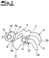
Fig. 2 das Kraftfahrzeug-Schloss nachFig. 1 in geschlossenem Zustand, konkret in der Durchschlagschutzstellung, -
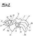
Fig. 3 das Kraftfahrzeug-Schloss nach denFig. 1 und2 in der Hauptrastposition und -
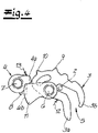
Fig. 4 das Kraftfahrzeug-Schloss nach derFig. 3 beim Übergang in eine Überhubstellung bzw. Ausweichstellung.
-
1 the motor vehicle lock according to the invention in the form of a motor vehicle hood lock during a closing process, starting from the open position, -
2 themotor vehicle lock 1 in the closed state, specifically in the puncture protection position, -
3 the motor vehicle lock after the1 and2 in the main detent position and -
4 the motor vehicle lock after the3 during the transition to an overtravel position or evasive position.
In den Figuren ist ein Kraftfahrzeug-Schloss dargestellt, bei dem es sich im konkreten Beispielfall um ein Kraftfahrzeug-Haubenschloss handelt. Das heißt, das fragliche Kraftfahrzeug-Schloss befindet sich im Bereich einer Kraftfahrzeug-Fronthaube 1, die im Rahmen der Darstellung nach der
Anhand der den Schließvorgang darstellenden
Die Drehfalle 3 sorgt nun beim Schließvorgang des Gesperres 3, 4 durch ihre Uhrzeigersinndrehung dafür, dass auch die Sperrklinke 4 verschwenkt wird. Tatsächlich kommt es an dieser Stelle zu einer Bewegung der Sperrklinke 4 im Gegenuhrzeigersinn um ihre Achse 7, wie ebenfalls in der
Im Hinblick auf den konstruktiven Aufbau sei noch darauf hingewiesen, dass die Sperrklinke 4 mit einem der Drehfalle 3 zugeordneten Begrenzungsfortsatz 8 ausgerüstet ist. Der Begrenzungsfortsatz 8 sorgt dafür, dass Schließbewegungen der Drehfalle 3 - nach dem Ausführungsbeispiel im Uhrzeigersinn um die zugehörige Achse 6 - begrenzt werden. Das heißt, der Begrenzungsfortsatz 8 sorgt für einen sogenannten Durchschlagschutz, wie dies nachfolgend noch näher erläutert wird. Zu diesem Zweck stellt der Begrenzungsfortsatz 8 im Rahmen der Erfindung einen festen bzw. integralen Bestandteil der Sperrklinke 4 dar.With regard to the structural design, it should also be pointed out that the
Die Sperrklinke 4 ist neben dem Begrenzungsfortsatz 8 zusätzlich mit wenigstens einem Sperrzahn 4a, 4b ausgerüstet. Nach dem Ausführungsbeispiel verfügt die Sperrklinke 4 über einen ersten Sperrzahn 4a und einen zweiten Sperrzahn 4b. Der erste Sperrzahn 4a ist dabei frontseitig der Sperrklinke 4 angeordnet, während der zweite Sperrzahn 4b als in Richtung der Achse 7 der Sperrklinke 4 versetzter Vorsprung gegenüber dem ersten Sperrzahn 4a ausgebildet. Für die nachfolgenden Betrachtungen ist primär der erste Sperrzahn 4a relevant.In addition to the limiting
Man erkennt, dass der Begrenzungsfortsatz 8 und der Sperrzahn 4a bzw. 4b jeweils umfangsseitig von der Sperrklinke 4 abstehen. Außerdem ist die Auslegung so getroffen, dass sich der Begrenzungsfortsatz 8 und der Sperrzahn 4a bzw. 4b überwiegend radial im Vergleich zu der Achse bzw. Drehachse 7 der Sperrklinke 4 erstrecken.It can be seen that the limiting
Die Drehfalle 3 verfügt ihrerseits über zumindest einen Rastzahn 9, 10. Tatsächlich sind nach dem Ausführungsbeispiel ein Vorrastzahn 9 und ein Hauptrastzahn 10 realisiert. Grundsätzlich kann aber auch mit nur einem der beiden Rastzähne 9, 10 gearbeitet werden.The
Zum grundsätzlichen Aufbau gehört schließlich noch eine Schwinge 11, die drehfest mit der Drehfalle 3 gekoppelt sein mag. Die Schwinge 11 kann auch als integraler Bestandteil der Drehfalle 3 fungieren bzw. ausgebildet sein. Außerdem ist nach dem Ausführungsbeispiel ein elektromotorischer Antrieb 14 vorgesehen, welcher die Schwinge 11 und damit die Drehfalle 3 beaufschlagt, beispielsweise im Sinne eines Zuziehens, und zwar ausgehend von einer nachfolgend noch näher zu beschreibenden Vorrastposition in eine Hauptrastposition. Mit Hilfe des elektromotorischen Antriebes 14 wird die Drehfalle 3 in Schließrichtung, d.h. im Uhrzeigersinn um die Achse 6, zugezogen.Finally, the basic structure also includes a
Die Wirkungsweise ist wie folgt. Geht man zunächst von der geöffneten Position nach der
Bei diesem Vorgang kommt die Drehfalle 3 nach dem Ausführungsbeispiel mit ihrem Vorrastzahn 9 zur Anlage an dem ersten Sperrzahn 4a der Sperrklinke 4 und sorgt ausgehend von der geöffneten Position des Gesperres 3, 4 in der
Als Folge hiervon nimmt die Sperrklinke 4 die Position in der
Denn die Drehfalle 3 ist zusätzlich mit einer die Drehfalle 3 in Öffnungsrichtung beaufschlagenden Feder 12 ausgerüstet. Diese Feder 12 sorgt dafür, dass die Drehfalle 3 ausgehend von der Durchschlagschutzstellung nach der
Die Sperrklinke 4 wird ihrerseits mit einer Feder 13 in ihrer Schließrichtung beaufschlagt, das heißt im Uhrzeigersinn in Bezug auf die zugehörige Achse bzw. Drehachse 7 der Sperrklinke 4, wie die Figuren andeuten. Dadurch fällt die Sperrklinke 4 ausgehend von der Durchschlagschutzstellung nach der
Ausgehend von dieser Hauptrastposition in der
- 11
- Kraftfahrzeug-Fronthaubemotor vehicle bonnet
- 22
- Schließbolzen bzw. SchließbügelLocking bolt or striker
- 3, 43, 4
- Gesperrelock
- 55
- Maulmouth
- 66
- Achseaxis
- 77
- Drehachseaxis of rotation
- 88th
- Begrenzungsfortsatzboundary process
- 9, 109, 10
- Rastzahnratchet tooth
- 99
- Vorrastzahnpre-ratchet tooth
- 1010
- Hauptrastzahnmain ratchet
- 1111
- Schwingeswingarm
- 12, 1312, 13
- FederFeather
- 1414
- Antriebdrive
Claims (10)
dadurch gekennzeichnet, dass
der Begrenzungsfortsatz (8) einen integralen Bestandteil der Sperrklinke (4) darstellt.Motor vehicle lock, in particular motor vehicle bonnet lock, with a locking mechanism (3, 4) consisting essentially of a rotary latch (3) and a pawl (4), and with a limiting extension (8) assigned to the pawl (4) for closing movements of the rotary latch (3) ,
characterized in that
the limiting extension (8) is an integral part of the pawl (4).
Applications Claiming Priority (1)
| Application Number | Priority Date | Filing Date | Title |
|---|---|---|---|
| DE102020132422.7A DE102020132422A1 (en) | 2020-12-07 | 2020-12-07 | Motor vehicle lock, in particular motor vehicle hood lock |
Publications (1)
| Publication Number | Publication Date |
|---|---|
| EP4008865A1 true EP4008865A1 (en) | 2022-06-08 |
Family
ID=78824849
Family Applications (1)
| Application Number | Title | Priority Date | Filing Date |
|---|---|---|---|
| EP21000344.8A Withdrawn EP4008865A1 (en) | 2020-12-07 | 2021-12-07 | Motor vehicle lock, in particular motor vehicle bonnet lock |
Country Status (2)
| Country | Link |
|---|---|
| EP (1) | EP4008865A1 (en) |
| DE (1) | DE102020132422A1 (en) |
Citations (7)
| Publication number | Priority date | Publication date | Assignee | Title |
|---|---|---|---|---|
| FR2372299A1 (en) * | 1976-11-30 | 1978-06-23 | Cerdan Jacques | |
| DE2839070A1 (en) * | 1977-09-12 | 1979-04-19 | Mecanismes Comp Ind De | LOCK, IN PARTICULAR FOR THE DOORS OF AUTOMOBILES |
| DE102006026282A1 (en) | 2006-06-02 | 2007-12-06 | Witte-Velbert Gmbh & Co. Kg | Rotary-latch lock for motor vehicle, has latch rotating pawl in such a manner that limitation extension is controlled in movement path, where extension is carried along path by pawl and shifted-back into locked position after pivoting pawl |
| DE102008025604A1 (en) * | 2008-05-28 | 2009-12-03 | Bayerische Motoren Werke Aktiengesellschaft | Lock for engine bonnet of motor vehicle, has latch, ratchet or adjustable stop lever comprising locking projection cooperating with locking region at lever , ratchet or latch during swing-locking of bonnet |
| DE102011003808A1 (en) * | 2011-02-08 | 2012-08-09 | Bayerische Motoren Werke Aktiengesellschaft | Lock for flap of motor vehicle, comprises rotary latch, which is loaded by rotary latch spring in release position, where operating element, which indirectly adjusts intermediate portion |
| WO2015077549A1 (en) * | 2013-11-22 | 2015-05-28 | Gecom Corporation | Vehicle hood latches |
| DE102014201808A1 (en) | 2014-01-31 | 2015-08-06 | Kiekert Ag | Method for closing a motor vehicle hood |
Family Cites Families (2)
| Publication number | Priority date | Publication date | Assignee | Title |
|---|---|---|---|---|
| DE2020038A1 (en) | 1970-04-24 | 1971-11-04 | Kiekert Soehne Arn | Motor vehicle door lock |
| DE102010062700A1 (en) | 2010-12-09 | 2012-06-14 | Bayerische Motoren Werke Aktiengesellschaft | Lock for engine bonnet of motor vehicle, has transmission element acting together with catch element over inclined surface or projection at catch element, such that catch element is temporarily adjusted against clamping force of spring part |
-
2020
- 2020-12-07 DE DE102020132422.7A patent/DE102020132422A1/en active Pending
-
2021
- 2021-12-07 EP EP21000344.8A patent/EP4008865A1/en not_active Withdrawn
Patent Citations (7)
| Publication number | Priority date | Publication date | Assignee | Title |
|---|---|---|---|---|
| FR2372299A1 (en) * | 1976-11-30 | 1978-06-23 | Cerdan Jacques | |
| DE2839070A1 (en) * | 1977-09-12 | 1979-04-19 | Mecanismes Comp Ind De | LOCK, IN PARTICULAR FOR THE DOORS OF AUTOMOBILES |
| DE102006026282A1 (en) | 2006-06-02 | 2007-12-06 | Witte-Velbert Gmbh & Co. Kg | Rotary-latch lock for motor vehicle, has latch rotating pawl in such a manner that limitation extension is controlled in movement path, where extension is carried along path by pawl and shifted-back into locked position after pivoting pawl |
| DE102008025604A1 (en) * | 2008-05-28 | 2009-12-03 | Bayerische Motoren Werke Aktiengesellschaft | Lock for engine bonnet of motor vehicle, has latch, ratchet or adjustable stop lever comprising locking projection cooperating with locking region at lever , ratchet or latch during swing-locking of bonnet |
| DE102011003808A1 (en) * | 2011-02-08 | 2012-08-09 | Bayerische Motoren Werke Aktiengesellschaft | Lock for flap of motor vehicle, comprises rotary latch, which is loaded by rotary latch spring in release position, where operating element, which indirectly adjusts intermediate portion |
| WO2015077549A1 (en) * | 2013-11-22 | 2015-05-28 | Gecom Corporation | Vehicle hood latches |
| DE102014201808A1 (en) | 2014-01-31 | 2015-08-06 | Kiekert Ag | Method for closing a motor vehicle hood |
Also Published As
| Publication number | Publication date |
|---|---|
| DE102020132422A1 (en) | 2022-06-09 |
Similar Documents
| Publication | Publication Date | Title |
|---|---|---|
| EP2633140B1 (en) | Motor vehicle door lock | |
| EP3800310B1 (en) | Motor vehicle lock | |
| WO2019076399A1 (en) | Motor vehicle door lock | |
| EP3697989B1 (en) | Vehicle door lock | |
| WO2019076403A1 (en) | Motor vehicle door lock | |
| EP3445930B1 (en) | Motor vehicle door lock | |
| DE102014114347A1 (en) | Motor vehicle door lock | |
| EP3966412A1 (en) | Motor vehicle door lock | |
| EP4127369A1 (en) | Bonnet lock positive driving of pawl by rotary latch with double lift | |
| EP3640419B1 (en) | Motor vehicle lock for a motor vehicle door | |
| EP3117057B1 (en) | Motor vehicle door lock | |
| EP4008865A1 (en) | Motor vehicle lock, in particular motor vehicle bonnet lock | |
| DE102017124524A1 (en) | Motor vehicle door lock | |
| EP3679208B1 (en) | Vehicle door lock | |
| WO2020078507A1 (en) | Motor vehicle lock | |
| EP4115039B1 (en) | Motor vehicle lock, in particular motor vehicle side door lock | |
| WO2024012622A1 (en) | Motor vehicle lock | |
| DE102022115500A1 (en) | Motor vehicle locking device | |
| WO2023232179A1 (en) | Motor vehicle lock, in particular motor vehicle door lock | |
| DE102021127453A1 (en) | Motor vehicle lock, in particular motor vehicle door lock | |
| DE102021126589A1 (en) | Motor vehicle lock, in particular motor vehicle door lock | |
| DE102022122496A1 (en) | Motor vehicle lock | |
| WO2023104237A1 (en) | Motor vehicle lock | |
| DE102021127454A1 (en) | Motor vehicle lock, in particular motor vehicle door lock | |
| WO2023186205A1 (en) | Motor vehicle lock, in particular motor vehicle door lock |
Legal Events
| Date | Code | Title | Description |
|---|---|---|---|
| PUAI | Public reference made under article 153(3) epc to a published international application that has entered the european phase |
Free format text: ORIGINAL CODE: 0009012 |
|
| STAA | Information on the status of an ep patent application or granted ep patent |
Free format text: STATUS: EXAMINATION IS IN PROGRESS |
|
| 17P | Request for examination filed |
Effective date: 20211216 |
|
| AK | Designated contracting states |
Kind code of ref document: A1 Designated state(s): AL AT BE BG CH CY CZ DE DK EE ES FI FR GB GR HR HU IE IS IT LI LT LU LV MC MK MT NL NO PL PT RO RS SE SI SK SM TR |
|
| STAA | Information on the status of an ep patent application or granted ep patent |
Free format text: STATUS: THE APPLICATION IS DEEMED TO BE WITHDRAWN |
|
| 18D | Application deemed to be withdrawn |
Effective date: 20220921 |