EP4008858A2 - Tower structure - Google Patents
Tower structure Download PDFInfo
- Publication number
- EP4008858A2 EP4008858A2 EP21212380.6A EP21212380A EP4008858A2 EP 4008858 A2 EP4008858 A2 EP 4008858A2 EP 21212380 A EP21212380 A EP 21212380A EP 4008858 A2 EP4008858 A2 EP 4008858A2
- Authority
- EP
- European Patent Office
- Prior art keywords
- tower
- guy
- deflection
- foundation
- area
- Prior art date
- Legal status (The legal status is an assumption and is not a legal conclusion. Google has not performed a legal analysis and makes no representation as to the accuracy of the status listed.)
- Pending
Links
Images


Classifications
-
- E—FIXED CONSTRUCTIONS
- E04—BUILDING
- E04H—BUILDINGS OR LIKE STRUCTURES FOR PARTICULAR PURPOSES; SWIMMING OR SPLASH BATHS OR POOLS; MASTS; FENCING; TENTS OR CANOPIES, IN GENERAL
- E04H12/00—Towers; Masts or poles; Chimney stacks; Water-towers; Methods of erecting such structures
- E04H12/20—Side-supporting means therefor, e.g. using guy ropes or struts
Definitions
- Exemplary embodiments deal with tower structures, foundations for supporting towers and wind turbines.
- On-shore wind turbines require large hub heights (e.g. > 140m) and large rotor diameters (e.g. > 130m) for economic operation.
- large hub heights and large rotor diameters large tower base diameters are required for the towers of the wind turbines in order to be able to absorb the bending moments that occur.
- general transport conditions such as clearance heights on land, limit the maximum possible diameter for tower sections to 4.4 m.
- guy lines are attached to the tower and extend from a certain tower height of the wind turbine down to the ground.
- effective guying requires a lot of space on the ground, since the guy ropes required for the guying are usually stretched around the wind turbines at a distance of 40-100m on the ground.
- a larger space requirement on the ground is associated with higher costs for securing the area and higher requirements for the topology of the terrain.
- guy lines Another aspect of guy lines relates to the attachment of the guy lines to the tower. Due to the attachment, the high loads that are transferred to the tower via the guy ropes often have a negative effect on the buckling behavior of the tower structure.
- a tower structure comprises a tower along a vertical tower axis and a guy rope that extends from a first guying direction to a deflection structure on or in the tower and extends from the deflection structure in a second guying direction towards the ground, with the first guying direction extending from the second guying direction, with the first guying direction and the second guying direction forming an angle of less than 180° in a top view, with the tower axis lying outside an area that is delimited by the guy rope between the first guying direction and the second guying direction.
- a tower structure in one embodiment, includes a tower along a vertical tower axis and a foundation for supporting the tower, the tower standing on the foundation, the foundation having an outer force deflection area radially spaced from the tower axis.
- the tower structure also includes a first guy structure, the first guy structure extending from the outer force deflection area to a part of the tower above the foundation, the first guy structure or a second guy structure coupled to the first guy structure at the outer force deflection area extending from the outer force deflection area to an inner guying area below the outer force deflection area, wherein a radial distance of the inner guying area from the tower axis is smaller than the radial distance of the outer force deflection area.
- a tower structure comprises a tower along a vertical tower axis and a foundation for supporting the tower, the tower standing on the foundation, the foundation having an outer force deflection area which is outside a base of the tower.
- the tower structure also includes a guying structure that extends from an outside of the tower to the outer force deflection area and from the outer force deflection area through an opening in the foundation from underneath the tower to a fastening structure inside the tower.
- Some embodiments relate to foundations for supporting a tower.
- the foundation includes a first arm extending a maximum radial distance from a midpoint of a tower deployment area of the foundation in a first direction.
- the foundation further includes a second arm extending in a second direction to a maximum radial distance from a center point of the tower erection area of the foundation, the foundation extending between the first arm and the second arm at least to a minimum radial distance from the Center of the tower erection area of the foundation extends, the minimum radial distance being at least 25% and a maximum of 70% of the maximum radial distance of the first arm.
- a tower structure includes a tower along a vertical tower axis and a guy rope that extends from a first guy direction to a deflection structure on or in the tower and extends from the deflection structure in a second guy direction towards the ground.
- the first guying direction differs from the second guying direction.
- the first guying direction and the second guying direction form an angle of less than 180° in a plan view.
- the tower axis lies outside of an area that is delimited by the guy rope between the first guying direction and the second guying direction.
- the guy rope can be used to brace the tower, so that a bending stress on the tower can be reduced.
- the guy rope can be pretensioned via a device in the ground, so that a tensile force absorbed by the guy rope can be introduced into the device in the ground.
- the guy rope can be connected to the tower via the deflection structure.
- the deflection structure can deflect the guy rope from the first guy direction to the second guy direction. Through the deflection of the guy rope on or in the tower can take place via the guy rope load introduction into the tower over a large area.
- the tower can be stressed more evenly due to the areal load application.
- the position of the tower axis outside of the area delimited by the guy rope between the first guying direction and the second guying direction can enable the guy rope to be deflected eccentrically to the tower axis.
- An eccentric deflection can bring about a more efficient introduction of force into the tower.
- the first guying direction and the second guying direction do not have to point to the tower axis.
- the tower could be designed within the transport framework of, for example, 4.40 m. For example, an additional subdivision of tower sections can be avoided.
- the deflection structure can be designed in such a way that the guy rope can be deflected from the first to the second guying direction.
- the deflection structure can absorb a force transmitted by the guy rope as a compressive force and can introduce it into the tower if it is arranged inside the tower, for example.
- a portion of the guy rope may be coupled to the deflection structure.
- a portion of the guy line may rest on the baffle structure, or a portion of the guy line may extend through the baffle structure.
- the deflection structure can be made of steel, for example, and connected to the tower, e.g. welded or bolted, in such a way that a load can be introduced over the entire surface of the tower.
- the deflection structure can be designed and connected to the tower in such a way that the first and second guying direction can be aligned eccentrically to the tower axis.
- the deflection structure can be formed on or in the tower.
- the baffle structure may be coupled to an inside of the tower wall or an outside of the tower wall.
- the deflection structure By arranging the deflection structure inside the tower, it can be protected, for example, from external influences, such as moisture.
- the deflection structure By connecting the deflection structure to an outer tower wall, the deflection of the guy rope can take place at a greater distance from the tower axis and/or a passage of the guy rope through the tower wall can be avoided.
- the force acting on the tower wall can differ depending on the arrangement of the deflection structure relative to the tower axis or to the tower wall.
- the top view can be a cross-section perpendicular to the axis of the tower or, in general, can include a representation that runs essentially perpendicular to the axis of the tower.
- the first guying direction and the second guying direction can, for example, enclose an angle greater than 30°, 40°, 60°, 90°, 120° or 150°.
- the first guying direction and the second guying direction can form an angle greater than 10° (or greater than 30°, 40°, 60°, 90°, 120° or 150°) in a plan view.
- the section of the guy rope that is coupled to the deflection structure and the section of the guy rope that extends outside of the deflection structure in the first and second guy directions can together enclose an area that does not include the tower axis.
- the first guying direction and the second guying direction can be aligned towards the ground.
- first and the second guying direction can point in the direction of an area that is located below the deflection structure with respect to the tower axis.
- the area below the baffle structure may include, for example, a tower section below the baffle structure, the tower base, the foundation, the surface just above the ground, or a portion of the ground.
- the first guying direction can be directed to a first point on the ground (and/or be directed from the first point to the deflection structure) and the second guying direction can be directed to a second point on the ground (and/or from the second point to the deflection structure be directed).
- the first point on the ground and/or the second point on the ground are at a distance from the tower wall of more than 2 m (or more than 5 m or more than 10 m).
- the distance from the tower wall of the first point on the ground can differ by less than 1m or less than 50% from the distance from the tower wall of the second point on the ground.
- the guy rope can be any rope structure that makes it possible to absorb a tensile force and transfer it to the deflection structure.
- the guy rope is a steel cable.
- the guy rope can extend to the ground (eg to an anchorage on the foundation) or be part of a multi-part guy structure which, in addition to the guy rope, comprises one or more rope sections, one or more chains or one or more rods.
- a multi-piece guy structure can have sections with different diameters, include shapes, structures or materials.
- the guy rope is bent around the deflection structure, for example, for alignment in the first and second guy direction.
- the tower can be any high facility that extends from the ground to a height.
- the tower for example, has a height that is many times greater than its diameter.
- the tower can be tensioned using the guy ropes.
- the tower can have several tower sections.
- the tower may be more than 50m, more than 80m, more than 100m, more than 120m, more than 140m, more than 160m or more than 180m high.
- the tower can be braced at different heights.
- the tower may include tower sections made of steel.
- the tower axis may be perpendicular to, for example, a floor, a foundation of the tower, or a surface for erecting the tower.
- the vertical tower axis can be parallel to the direction of gravity.
- the vertical tower axis can deviate from the direction of gravity by a maximum of 5mm per meter of tower height (without taking into account an inclined position of the foundation) or a maximum of 8mm per meter of tower height (taking into account an inclined position of the foundation).
- the tower structure can include more than one guy rope and more than one deflection structure.
- a tower structure can include two, three or more guy ropes and/or deflection structures.
- Guy ropes and deflection structures can be distributed on the tower in such a way that the tower can be loaded as evenly as possible.
- guy ropes and deflection structures can be arranged symmetrically or at the same angle with respect to the tower axis or to one another.
- a tower structure may include as many guy wires as turning structures, more guy wires than turning structures, or fewer guy wires than turning structures.
- the tower to be erected comprises, for example, a plurality of tower sections arranged one above the other, which can be designed in one piece or in multiple pieces.
- the tower section can be designed in one piece if they are manufactured within the transport frame conditions of, for example, 4.4 m.
- the tower or all tower sections of the tower may have a maximum diameter of maximum 4.5m (or maximum 4m or maximum 3.5m), for example at a height of more than 120m (or more than 140m, more than 160m or more than 180m).
- the tower wall or shell of the tower or the tower section can be, for example, in the shape of a cylinder jacket or a truncated cone jacket and/or a steel shell or sheet steel shell.
- the tower wall or the tower shell can have a thickness of more than 20 mm, 30 mm, 40 mm or more, for example.
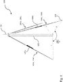
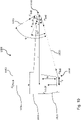
- FIG 1 shows an embodiment of a tower structure 100 with a tower 102 along a vertical tower axis 104 and three guy ropes 106a-c.
- a guy rope such as guy rope 106a, extends from a first guy direction 107a to a deflection structure on or in the tower 102 and extends from the deflection structure in a second guy direction 108a toward the ground.
- the first guying direction 107a differs from the second guying direction 108a.
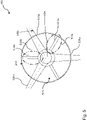
- FIG 2 for example, a top view 201 of the tower structure 100 with deflection structures 210a-c on a tower wall 203.
- the first guying direction 107a and the second guying direction 108a of the guy rope 106a form an angle ⁇ of less than 180°.
- the tower axis 104 lies outside of a region which is delimited by the guy rope 106a between the first guying direction 107a and the second guying direction 108a.
- the tower axis 104 lies in the range 360°- ⁇ , which is delimited by the guy rope 106a.
- first guy direction and the second guy direction in a top view can form an angle of less than 180° (or less than 160°, less than 130°, less than 100° or less than 80°) and/or greater than 10° (or greater than 20°, greater than 30°, greater than 40°, greater than 60°, greater than 90°, greater than 120° or greater than 150°).
- the other guy ropes 106b-c can also be deflected at the corresponding deflection structures 210b-c.
- the guy rope 106b extends from a third guy direction to the deflection structure 210b on or in the tower 102 and extends from the deflection structure 210b in a fourth guy direction towards the ground.
- the deflection structures 210a-c are connected to the tower wall 203 of the tower 102 in such a way that forces transmitted from the guy ropes 106a-c to the deflection structures 210a-c act on the tower wall 203 transfer.
- 2 shows an example of the direction of the cable pull forces Fs, which can occur on the guy cables 106a-c due to a force acting on the tower 102.
- the guy ropes 106a-c can transfer tensile forces Fs to the tower wall 203 by means of the deflection structures 210a-c.
- a load can be introduced into the tower wall 203 over a large area.
- the tower wall 203 can be stressed evenly, so that the tower 102 or the tower wall 203 can absorb greater forces up to fatigue.
- the rope force F S that occurs can partly act tangentially to the tower 102 .
- the cable force F S acting on the tower 102 can counteract any torsional moments M t or can contribute to a torsionally more rigid clamping in the guying plane.
- the tower structure 100 can be braced eccentrically to the tower axis 104 by means of the guy ropes 106a-c, which are deflected via the deflection structures 210a-c.
- the guy ropes 106a-c do not have to be aligned with the tower axis 104 or the first and the second guying direction 107a and 108a do not have to point towards the tower axis 104 for effective guying.
- the tower structure 100 is explained in more detail in connection with the guy rope 106a and the deflection structure 210a.
- the explanations can also refer to the guy ropes 106b-c and the deflection structures 210b-c.
- the guy rope 106a can be referred to as the first guy rope
- the deflection structure 210a can be referred to as the first deflection structure.
- the guy rope 106b or 106c can be referred to as a further, different second or third guy rope and the deflection structure 210b or 210c can be referred to as a further, different, second or third deflection structure.
- inventions may include more than three guy lines and diversion structures. If appropriate, other exemplary embodiments can include at least a first guy rope 106a and a first deflection structure 210a as described above and can be combined with another guying method for guying the tower structure 100 .
- the contact surface 312, 412 serves as a support surface or an area for laying on a guy rope 106a.
- the contact surface 312 of the deflection structure 310 in 3 is formed in a groove-shaped depression on a surface of the deflection structure 310 . Since the contact surface 312 is formed on a surface of the deflection structure 310, the deflection structure 312 can also be referred to as an open cable support. In 4 it can be seen that the deflection structure 410 has a tubular region. The contact surface 412 is formed in the tubular area of the deflection structure 410 .
- the deflection structure 410 can also be referred to as a closed cable support.
- the contact surfaces 312, 412 of the deflection structures 310, 410 can be aligned with a shape or contour of the guy rope 106a.
- the groove-shaped indentation in 3 or the diameter of the tubular portion may be matched to a thickness of the guy rope 106a.
- the contact surfaces 312 and 412 of the deflection structures 310 and 410 can be formed according to the first and second anchoring direction 107a and 108a.
- the deflection structure 410 can make it possible that a lying guy rope 106a cannot fall out of the tubular area due to the closed shape.
- Deflection structures in a closed form can protect guy ropes from moisture, for example.
- Deflection structures, such as cable supports, can be solid welded or cast constructions in addition to the open or closed type.
- the contact surface 312, 412 of the deflection structure 310, 410 has a curvature with a radius of curvature. For example, twice the radius of curvature is greater than a minimum bending roller diameter of a guy rope 106a resting on it.
- the restriction of the curvature of the contact surface 312, 412 according to the minimum bending roller diameter of the guy rope 106a can be useful in order not to damage the deflection structure 310, 410 and the guy rope 106a as a result of excessive pressure.
- the contact surface 312, 412 By limiting the contact surface 312, 412 to a maximum curvature, it can be ensured, for example, that the compressive strength of the material of the deflection structure, such as steel, is not exceeded and/or the guy rope is not excessively deformed or damaged.
- a permissible smallest bending or deflection radius, for example for a wire rope, can be adjusted to 18 times the rope diameter.
- the guy rope 106a can be deflected on or in the tower by means of the deflection structure 310, 410, so that the tower structure 100 can be guyed.
- the guy rope 106a can be placed on the deflection structure 310, 410 in such a way that a complicated attachment of the guy rope 106a on or in the tower 102 can be avoided.
- the contact surface 312 or 412 can have a property such that a coefficient of friction between the contact surface 312, 412 and the guy rope 106a is so high that a pretension of the guy rope 106a or a fastening device creates a frictional connection between the deflection structure 310, 410 and the guy rope 106a arises.
- the guy rope 106a can also be arranged or attached differently to the deflection structure 210a, 310, 410. If appropriate, the guy rope 106a can be glued, wired, hooked, screwed, welded or pressed to the deflection structure 210a, 310, 410 at least in individual areas.
- deflection structures 210a-c, 310, 410 are described in connection with the proposed concept or one or more of the examples described above or below.
- figure 5 shows another example of a top view 501 of a tower structure, such as tower structure 100 in 1 . It is shown that a deflection structure 510a of the guy rope 106a and a second deflection structure 510b of the guy rope 106b are formed in a deflection arrangement 520 .
- the deflection structures 510ab are arranged in the interior of the tower 102 and connected to an inner side of the tower wall 203 by the deflection arrangement 520 .
- the deflection arrangement 520 comprises the deflection structure 510a and the second deflection structure 510b and has a central open area through which the tower axis 104 runs.
- Each deflection structure 510a-b comprises at least one connecting element 514a-b, which connects a part of the deflection structure comprising the contact surface to the inside of the tower wall 203 connects.
- the guy rope 106a runs through the tubular portion of the turning structure 510a and is turned from a first direction to a second direction.
- the connecting element 514a, 514b can be designed in such a way that a force transmitted from the guy rope 106a, 106b to the deflection structure 510a-b can be efficiently forwarded or distributed to the tower wall 203.
- the connecting element 514a of the deflection structure 510a can correspond to a cylinder with the same diameter or a tube.
- the arrangement of the connecting element 514a can be aligned with a center or an axis of symmetry of the contact surface in the deflection structure 510a.
- the ends of the connecting element 514a can be adapted for a suitable fastening, for example to the tower wall 203, such as rounded off or additionally equipped with a fastening element.
- the one end of the connecting element 514a that faces the tower wall 203 can have a larger diameter than the opposite end of the connecting element 514a.
- connector 514a is cone-shaped.
- the deflection structure 510a may include two or more connection elements 514a. The two or more connecting elements 514a can be connected to the tower wall 203 at a distance from one another within an area bounded by the guy rope 106a. Two or more connecting elements 514a can contribute to a more even load distribution of the force transmitted by the guy rope on the tower wall 203.
- the central open portion of the baffle assembly 520 is annular or tubular.
- the central open area may be oval, rectangular, square, star-shaped, trapezoidal, symmetric, asymmetric, or solid.
- the deflection arrangement 520 can contribute to a deflection of the guy ropes 106a-c in the tower interior closer to the tower axis 104.
- the deflection structures can be formed in a common component.
- the tower wall 203 has at least two openings 516a, through which the guy rope 106a is guided from the outside to the deflection structure 510a inside the tower.
- the guy rope 106a can extend through the openings 516a from the ground into the interior of the tower and are deflected back towards the ground inside the tower.
- the openings 516a can, for example, be designed by their shape or size in such a way that mobility of the guy rope 106a or access of the guy rope 106a into the interior of the tower is not restricted as far as possible.
- the openings 516a can be designed in such a way that, for example, the interior of the tower is sealed off.
- Deflection structures can be arranged inside the tower through the openings. By arranging the deflection structures inside the tower, the deflection structures or the deflection arrangement 520 can be protected from external influences, such as moisture occurring in bad weather. Sections of the guy rope, such as the section of the guy rope that is deformed by the deflection, can also be protected by the deflection inside the tower.
- deflection structures can be arranged on an outer wall of the tower 102 .
- the arrangement of the deflection structures on an outer wall can be preferred, for example, because it is easier to attach to the tower.
- Deflection elements on an outer wall can be used to deflect guy ropes at a greater distance from the tower axis.
- Deflection elements on an outer wall can be designed differently, e.g. in terms of shape, size or contact area, than deflection structures for a tower inner wall.
- Deflection structures can be connected to the tower wall via a welded joint.
- baffle structures may be glued, wired, hooked, bolted, or riveted to a tower wall.
- guy lines 106a and 106b may extend to a common area toward the ground.
- the first guy rope 106a and the second guy rope 106b can be attached to a foundation structure 105 (e.g. anchor point or guy structure) in the ground at a distance of less than 1 m, such as 0.5 m, 0.3 m or 0.1 m, or can be deflected .
- guy ropes may be tensioned using discrete foundation structures, such as concrete, positioned above the site subsoil. The forces absorbed by the foundation structures can be transmitted to the ground.
- the guy ropes 106a-b can also be deflected at the foundation, for example.
- 6 shows an embodiment of a tower structure 600 with a deflection of the guy ropes 606 on a foundation 630 in the ground. Further details on the deflection of the guy ropes on the foundation are given below in connection with the 10 and 11 executed.
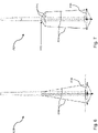
- the tower structure 700 includes deflection structures that are formed on or in the tower at a height 725.
- the deflection elements 724 are connected to an outside of the tower wall and are arranged at a lower height than the height 725 of the deflection structure on the tower.
- the guy rope 706 extends over the deflection element 724 in the first guy direction to the deflection structure or the guy rope 706 extends from the second guy direction of the deflection structure over the deflection element 724 in the direction of the ground.
- the deflection element 724 is designed to at least partially transfer a tensile force of the guy rope 706 into a compressive force acting on the tower.
- the deflection element 724 can be a frame or a strut.
- the length of the deflection element 724 can be smaller than the distance between the radius of the tower outer wall and the radius of the foundation 730, for example.
- the deflection elements 724 can cause a distribution of the compressive forces acting on the tower. Due to the deflection elements 724, the tower or the tower wall can also absorb pressure forces at a lower height than the height 725 of the deflection elements 724.
- the deflection elements 724 can enable the tower structure 700 to be braced effectively with a smaller radius around the tower axis. This allows, for example, guy ropes with a smaller radius to be attached to the ground, tensioned or deflected. Furthermore, the effect of rope pretension can be increased with a reduced anchoring radius. A smaller radius guying allows for easier attachment or deflection to a foundation structure or foundation. A smaller guy radius can mean that less space is required for guying the tower structure. Due to the lower land use, a restriction to agricultural use can be reduced or avoided. Through a lower land use can reduce the requirements for a terrain topology, for example for the installation of the tower structure.
- tower structure 600 or 700 Further details and optional aspects of the tower structure 600 or 700 are described in connection with the proposed concept or one or more of the examples described above or below.
- FIG. 8 shows a further embodiment of a tower structure 800 with a further guy rope 806d at a different guy height than the guy rope 106a.
- the guy rope 106a extends from a guy height of the tower towards the ground.
- the additional guy rope 806d extends from a second guy height in the direction of the ground.
- the (first) guy height of the (first) guy rope 106a differs from the second guy height of the further (second) guy rope 806d by more than 2 m.
- the difference between the guy heights can be 3m, 4m, 5m, 10m, 20m or more.
- a deflection of guy ropes at different guy heights can contribute to a compressive force acting on the tower wall at different tower sections, for example in order to distribute the load on the tower wall.
- deflection structures 210a-c, 310, 410 or several deflection arrangements 520 as in FIGS Figures 2-5 shown can be used.
- the deflection structures can be of the same type or of different designs.
- tower structure 800 Further details and optional aspects of the tower structure 800 are described in connection with the proposed concept or one or more of the examples described above or below.
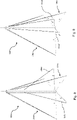
- FIG. 9 shows a further exemplary embodiment of a tower structure 900 with a further guy rope 906d with a different guy radius r 2 than the guy rope 106a.
- the guy rope 106a extends from the tower towards the ground with a guy radius r.
- the additional guy rope 906d extends from the tower in the direction of the ground with a different guy radius r ' .
- the (first) guy radius r of the (first) guy rope 106a differs from the guy radius r′ of the further (second) guy rope 906d by more than 0.5 m, more than 1 m, more than 2 m or more than 3 m.
- Fastening or deflecting guy ropes at different guy radii can allow a different force to be applied or transmitted to the tower wall, for example through a steeper course of force.
- For a more effective bracing can, for example, additionally stabilize the tower structure 900 with bracing cables with a bracing radius r′ that is smaller or larger than r.
- tower structures can include guy ropes with different guy radii and guy heights.
- a first guy rope can extend below a second guy rope by crossing both guy ropes.
- a first guy rope with a different guy radius and/or a different guy height can extend below a second guy rope from the ground towards the tower.
- Cable guying can be used above all with high towers or masts and can enable a slim construction of the tower structure.
- a tower structure can include 4, 5, 6 or more guy ropes in different guy directions.
- the tower structure can be braced symmetrically or asymmetrically, e.g. to enable better load distribution.
- the tower structure includes a tower along a vertical tower axis and a foundation for supporting the tower, the tower standing on the foundation.
- the foundation has an outer force deflection area that is radially spaced from the tower axis.
- the tower structure includes a first guying structure.
- the first guy structure extends from the outer force deflection area to a part of the tower above the foundation.
- the first anchoring structure or a second anchoring structure coupled to the first anchoring structure at the outer force deflection area extends from the outer force deflection area to an inner anchoring area below the outer force deflection area.
- a radial distance of the inner anchoring area from the tower axis is smaller than the radial distance of the outer force deflection area.
- the foundation can absorb a weight or at least a part of the weight of the tower and transfer it to the ground.
- the foundation can be coupled to the tower and allow vertical alignment of the tower along the tower axis.
- the tower structure can be braced using the guying structure(s) in order to be able to reduce bending stress on the tower.
- the anchoring structure can absorb a tensile force.
- the tensile force on the first guying structure, optionally coupled to the second guying structure can be deflected via the outer force deflection area of the foundation.
- the first guying structure can be deflected at the outer force deflection area or the first guying structure can be coupled to the second guying structure so that at least one guying structure can extend from the tower above the foundation in the direction below the foundation to the inner guying area.
- the inner anchoring area can allow attachment, tensioning or deflection of the first or second anchoring structure below the foundation. Fastening, tensioning or deflection of the guying structure on the inner guying area can take place closer to the tower axis, compared to the outer force deflection area. Due to the force deflection at the outer force deflection area and the inner guying area, the tensile force acting in the guying structure can be introduced as a compressive force into the foundation or into a device coupled to the foundation.
- the inner anchoring area can be formed on the foundation or on the device coupled to the foundation.
- the force deflection or force conversion can enable effective guying of the tower with a smaller guying radius.
- a maximum anchoring radius can be limited to the radial distance of the outer force deflection area via the outer force deflection area.
- a smaller guy radius can reduce the space required by the tower structure.
- a smaller space requirement can reduce costs for securing the tower structure or reduce demands on the terrain topology of the tower structure.
- the foundation can be any object suitable for supporting the tower.
- the foundation can be made of reinforced concrete, for example.
- the foundation can be circular or angular or comprise several arms when viewed from above, e.g. aligned perpendicularly to the tower axis. For example, several arms can form a cruciform or star-shaped foundation.
- the foundation can have the outer force deflection area on its outer boundary or on the outer edge.
- the outer force deflection area can be formed, for example, by a specific shape of the outer edge of the foundation.
- the outer force deflection area can be formed, for example, by a rounding, a depression, a bulge, an elevation or an additional device on the outer edge of the foundation.
- An additional device can be, for example, a fastening device or an element for coupling the first and second anchoring structure.
- the outer force deflection area can determine the distribution of forces in the bracing structure and in the foundation.
- the inner guying area can be located below the foundation and optionally also below the tower.
- the inner anchoring area can be a part of the foundation that has a smaller radial distance from the tower axis than the radial distance of the outer force deflection area.
- the inner stay area may be part of any structure so long as the inner stay area is below the foundation and at a smaller radial clearance than the radial clearance of the foundation.
- the inner guying area is e.g. a fastening device for attaching the guying structure to the foundation, a depression, a bulge, a ridge or a fillet for connecting, redirecting, wrapping the guying structure to/on/around the foundation or any device below the foundation.
- the radial spacing of the outer force deflection area can be, for example, more than 10 m, more than 20 m, more than 30 m and/or less than 50 m, less than 30 m or less than 20 m.
- the inner bracing area can, for example, be matched to the radial distance of the outer force deflection area and can be, for example, a radial distance of less than 5m, less than 10m, less than 15m.
- the inner anchoring area can, for example, have a depth of more than 1m, more than 1.5m, more than 2m relative to the outer force deflection area.
- the guy structure can absorb a tensile force and allow the absorbed tensile force to be transferred to the foundation and/or a device below the foundation.
- the anchoring structure is a steel cable, a steel chain or a combination of cables, chains and/or rods coupled to one another.
- the guying structure can be in one piece and can be formed, for example, by the first guying structure (e.g. a guy rope).
- the bracing structure can be in several parts and can be formed, for example, by the first and second bracing structure or other bracing structures.
- a two-piece or multi-piece guy structure may include sections of different diameters, shapes, textures, or materials.
- the anchoring structure can be deformed or bent at the outer force deflection area for deflection.
- the tower can be any high facility that extends from the ground to a height.
- Other versions of the tower can be as described above.
- the axis of the tower can be perpendicular e.g. Other versions of the tower axis can be as described above.
- the tower structure can include more than one guying structure, more than one outer force deflection area, and more than one inner guying area.
- a tower structure can comprise two, three or more guying structures, outer force deflection areas and/or inner guying areas.
- Guying structures, outer force deflection areas and inner guying areas can be distributed on or to the foundation in such a way that the tower can be loaded as evenly as possible.
- guy structures, outer force deflection areas and inner guy areas can be arranged symmetrically or at the same angle with respect to the tower axis or to one another.
- a tower structure may include as many guying structures as outer force deflection areas and/or inner guying areas, more guying structures than outer force deflection areas and/or inner guying areas, or fewer guying structures than outer force deflection areas and/or inner guying areas.
- FIG. 10 shows an embodiment of a tower structure 1000 with a tower 1002 along a vertical tower axis 1004 and a (eg first) foundation 1030 for carrying of the tower 1002.
- the tower 1002 stands on the foundation 1030.
- the foundation 1030 has an outer force deflection area 1032 which has a radial distance r from the tower axis 1004.
- the foundation 1030 has a first bracing structure 1036 .
- the first guying structure 1036 extends from the outer force deflection area 1032 to a part of the tower 1002 above the foundation 1030.
- the first guying structure 1036 extends from the outer force deflection area 1032 to an inner guying area 1038 below the outer force deflection area 1032.
- the radial distance r 2 of the inner anchoring area 1038 is smaller relative to the tower axis 1004 than the radial distance r of the outer force deflection area 1032.
- the first guy structure is coupled to a second guy structure at the outer force deflection area 1032 such that the second guy structure extends from the outer force deflection area 1032 to the inner guy area 1038 below the outer force deflection area 1032 .
- the first guying structure and the second guying structure can be viewed as a two-part guying structure 1036, which extends on the one hand from the outer force deflection area 1032 to a part of the tower 1002 above the foundation 1030 and on the other hand from the outer force deflection area 1032 to the inner guying area 1038 below the outer Kraftumlenk Scheme 1032 extends.
- the tower structure 1000 is considered in connection with the first (one-piece) guy structure 1036 . This is for convenience only and should not be construed as a limitation on the concept described.
- the bracing structure 1036 can be deflected on the foundation 1030 by the outer force deflection area 1032 . For example, this avoids fastening the guy structure 1036 to the foundation 1030, to the outer part of the foundation 1030 or to a separate anchoring element outside the foundation radius r.
- the bracing structure 1036 can be guided under the foundation 1030 through the outer force deflection area 1032 so that a force deflection and an introduction of compressive forces into the foundation 1030 can take place. Since the foundation material, such as concrete, can absorb higher compressive forces than tensile forces, this type of force deflection can enable an effective load distribution of the guying forces on the tower structure 1000.
- the foundation can be constructed as an in-situ concrete or precast foundation or a combination thereof.
- a guying with a smaller guying radius is carried out.
- Smaller guy radii can allow for a smaller space requirement for the tower structure 1000 .
- Other aspects regarding smaller guy radii can, as described above, in connection with 7 or 9 to be viewed as.
- the tower building in 10 shows the inner anchoring area 1038 as part of a second foundation 1031.
- the second foundation 1031 is located below the first foundation 1030.
- the second foundation 1031 can be made of a different material than the foundation 1030, for example.
- the second foundation 1031 can be connected to the foundation 1030 using a suitable fastening method in such a way that a suitable transmission of force to the foundation 1030 can take place.
- the second foundation 1031 may be spaced apart from the foundation 1030 .
- a material or medium suitable for power transmission can be located between the foundation 1030 and the second foundation 1031 .
- the material can come from the ground and can be earth, gravel or sand.
- the second foundation 1031 may be only partially below the foundation 1030 .
- portions of the second foundation 1031 may be outside of the foundation radius r of the foundation 1030 .
- the inner guy line 1038 may be part of the foundation 1030 .
- the second foundation 1031 is part of the foundation 1030.
- the pressure force F pressure transmitted from the first anchoring structure 1036 to the outer force deflection area 1032 can act on the foundation 1030 at an angle Y.
- the angle Y can enclose the angle between the pressure force F pressure at the outer force deflection area 1032 and the horizontal plane along the foundation 1030 perpendicular to the tower axis 1004 .
- the angle Y can be at least 15° and at most 30°.
- the angle Y can be 15°, 16°, 20°, 25° or 30°.
- the angle Y can be determined via the height H.
- the height H may correspond to the depth or distance of the inner anchoring area 1038 relative to an arm of the foundation 1030 .
- ⁇ as in 10 shown, includes the angle between the cable force F cable and the horizontal plane.
- the height H between the inner anchoring area and the foundation 1030 can be 1 m or more.
- a tower structure includes the foundation 1030 with a second outer force deflection area, which has a second radial distance r ′ from the tower axis 1004 .
- the second radial distance r′ of the second force deflection area differs from the (first) radial distance r of the (first) outer force deflection area 1030 by at least 20% of the (first) radial distance r.
- Another bracing structure extends from the second outer force deflection area to a part of the tower 1002 above the foundation 1030.
- a second outer force deflection area with a radial distance r' different from the radial distance r of the (first) outer force deflection area 1032 can be used to brace the Tower structure 1000 done with different bracing radii.
- tower structures with different bracing radii can promote a different force transmission or distribution on the tower wall.
- the first guy structure 1036 can be a guy rope that extends from the tower 1002 via the outer force deflection area 1032 to the inner guy area 1038.
- Further examples of bracing structures 1036 are chains, rods or other elements that are suitable for transferring an absorbed tensile force into a compressive force acting on the outer force deflection area 1032 .
- Tensioning structures can differ in terms of type, material, shape or diameter, or they can be in one piece or in multiple pieces.
- a guy structure is a combination of a first guy rope having a first diameter and extending above the foundation and a second guy line having a second diameter and extending below the foundation.
- a guy rope can be made of steel and have a thickness of 40-120mm.
- a guy rope made of steel can be designed as a stranded rope, for example as a round stranded rope, or as a spiral stranded rope, for example as a half or fully locked spiral rope.
- the steel guy rope can be designed as a low-stretch or electromechanical rope.
- the inner anchoring area 1038 can be equipped with a connecting or deflecting device on the foundation 1031 for connecting or deflecting the anchoring structure 1036 to/on the foundation 1038 .
- the guy structure 1036 may be connected to the foundation 1031 using, for example, a bolt, tube, loop, wrap, hook, flange, or other device for fastening, tensioning, or coupling the guy structure.
- the guying structure 1036 can be deflected in the direction of the tower 1002 via a further force deflection area on the foundation 1031 .
- the anchoring structure 1036 can be coupled to the tower 1002, for example, as a result of the deflection. This allows a force to be transmitted, e.g. to be introduced into the tower wall.
- tower structure 1000 Further details and optional aspects of the tower structure 1000 are described in connection with the proposed concept or one or more of the examples described above or below.
- a tower structure includes a tower along a vertical tower axis and a foundation for supporting the tower, with the tower standing on the foundation.
- the foundation has an outer force deflection area that lies outside a base area of the tower.
- the tower structure also includes a guying structure that extends from an outside of the tower to the outer force deflection area and from the outer force deflection area through an opening in the foundation from underneath the tower to a fastening structure inside the tower.
- the foundation can absorb a weight or at least a part of the weight of the tower and transfer it to the ground.
- the foundation can be coupled to the tower and allow vertical alignment of the tower along the tower axis. That
- the tower structure can be braced using the guying structure in order to be able to reduce bending stress on the tower.
- the anchoring structure can absorb a tensile force.
- the tensile force on the bracing structure can be deflected via the outer force deflection area of the foundation.
- the guying structure can be deflected at the outer force deflection area, so that the guying structure can extend from the outside of the tower above the foundation in the direction below the foundation through the opening in the foundation to the fastening structure inside the tower.
- the fastening structure can enable the guying structure to be coupled to the interior of the tower, for example to the inner wall of the tower. Due to the force deflection at the outer force deflection area and the attachment structure inside the tower, the tensile force acting in the guying structure can be introduced into the foundation as a compressive force. In addition, the force transmitted by the guying structure can act on the inside of the tower.
- the force deflection or force conversion can enable effective guying of the tower with a smaller guying radius.
- a maximum anchoring radius can be limited to the radial distance of the outer force deflection area via the outer force deflection area.
- a smaller guy radius can reduce the space required by the tower structure. A smaller space requirement can reduce costs for securing the tower structure or reduce demands on the terrain topology of the tower structure.
- the foundation can be any object suitable for supporting the tower.
- the foundation can be made of reinforced concrete, for example.
- the foundation can be circular or angular or comprise several arms when viewed from above, e.g. aligned perpendicularly to the tower axis.
- several arms can form a cruciform or star-shaped foundation.
- the foundation can have an opening through which the guy structure can extend from below the foundation in the direction of the inside of the tower.
- the opening may be round, square, or tubular.
- the opening may encompass the tower axis or may be offset from the tower axis.
- the opening in the foundation can be designed as a cavity that can be used for arranging equipment or devices, for example.
- the foundation can have the outer force deflection area on its outer boundary or on the outer edge.
- the outer force deflection area can be outside of a base area of the tower, for example the erection area of the tower or the area delimited by an outer wall of the tower.
- the outer Kraftumlenk Scheme example, by a specific shape of the outer edge of the foundation.
- the outer force deflection area can be formed, for example, by a rounding, a depression, a bulge, an elevation or an additional device on the outer edge of the foundation.
- An additional device can be, for example, a fastening device or an element for coupling a two- or multi-part guy structure.
- the outer force deflection area can, for example, determine the distribution of forces in the anchoring structure and in the foundation through its position, its shape or its structure.
- the mounting structure may be located inside the tower, such as on the inside wall of the tower.
- the interior guying area can be a part of the tower structure, such as a flange, or any device for coupling the guying structure to the tower interior (e.g., an inside of the tower wall).
- the mounting structure may be located above the foundation and may have a smaller radial distance from the tower axis than the radial distance of the outer force deflection area.
- the radial spacing of the outer force deflection area can be more than 10m, more than 20m, more than 30m or more, for example.
- the fastening device can, for example, be the deflection structure according to the embodiments described above.
- the fastening device can be a depression, a bulge, an elevation, an opening or a rounding for connecting or deflecting the guying structure to/on the inside of the tower.
- the guying structure can absorb a tensile force and enable the absorbed tensile force to be transmitted to the foundation and into the interior of the tower by means of the fastening structure.
- the anchoring structure is a steel cable, a steel chain or a combination of rods coupled to one another.
- the anchoring structure can be in one piece and can be formed, for example, by the first anchoring structure.
- the bracing structure can be in several parts and can be formed, for example, by the first and second bracing structure or other bracing structures.
- a two-piece or multi-piece guy structure may include sections of different diameters, shapes, textures, or materials.
- the bracing structure can be deformed at least in the outer force deflection area.
- the tower can be any high facility that extends from the ground to a height.
- Other versions of the tower can be as described above.
- the axis of the tower can be perpendicular e.g. Other versions of the tower axis can be as described above.
- the tower structure can include more than one guying structure, more than one outer force deflection area, and more than one attachment structure.
- a tower structure can include two, three or more guy structures, external force deflection areas and/or attachment structures. Bracing structures, external force deflection areas and attachment structures can be distributed on or to the foundation in such a way that the tower can be loaded as evenly as possible.
- guy structures, outer force deflection areas and attachment structures can be arranged symmetrically or at the same angle with respect to the tower axis or to one another.
- a tower structure may include as many guy structures as outer force deflection areas and/or attachment structures, more guy structures than outer force deflection areas and/or attachment structures, or fewer guy structures than outer force deflection areas and/or attachment structures.
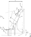
- FIG. 11 shows another embodiment of a tower structure 1100 with a tower 1102 along a vertical tower axis 1104 and a foundation 1130 for supporting the tower 1102.
- the tower 1102 stands on the foundation 1130.
- the foundation 1130 has an outer force deflection area 1132, which is outside a base area of the Tower 1102 is located.
- the tower structure 1100 includes a guying structure 1136, which extends from an outside of the tower 1102 to the outer force deflection area 1132 and from the outer force deflection area 1132 through an opening 1139 in the foundation 1130 from below the tower 1102 to a fastening structure 1140 inside the tower.
- the bracing structure 1136 can be deflected on the foundation 1130 by the outer force deflection area 1132 . For example, this can avoid fastening the guy structure 1136 to the foundation 1130, to the outer part of the foundation 1130 or to a separate anchoring element outside the foundation radius r.
- the bracing structure 1136 can be guided under the foundation 1130 through the outer force deflection area 1132 so that a force deflection and an introduction of compressive forces into the foundation 1130 can take place. Because the foundation material, such as concrete, higher compressive forces than tensile forces, this type of force deflection can enable an effective load distribution of the guying forces on the tower structure 1100.
- guying can be done with a smaller guying radius due to a more effective load deflection in the tower structure 1100 .
- Aspects of smaller bracing radii can refer to the explanations in connection with 7 , 9 and 10 relate.
- the tower structure 1100 does not have an inner anchoring area that is located below the outer force deflection area 1132.
- the guying structure 1136 is coupled to a fastening structure 1140 inside the tower, so that a force transmitted via the guying structure 1136 can be introduced into a tower structure, for example.
- the attachment structure 1140 is attached to the tower wall of the tower 1102 or to a transverse flange or longitudinal flange of the tower 1102 .
- the tower structure 1100 has an inner force deflection area 1138 via which the guying structure 1136 is guided into the interior of the tower. As in 11 shown, the guying structure 1136 extends from the outer force deflection area 1132 via the inner force deflection area 1138 to the attachment structure 1140.
- the outer force deflection area 1132 has a first radial distance r from the tower axis 1104 and is arranged at a first depth T 1 .
- the inner force deflection area 1138 has a second radial distance r 2 from the tower axis 1104 and is arranged at a second depth T 2 .
- the second radial distance r 2 is smaller than the first radial distance r and the first depth T 1 is greater than the second depth T 2 .
- the first depth T 1 of the outer force deflection area 1132 is at least 1m greater than the second depth T 2 of the inner force deflection area 1138.
- the depth T 1 of the outer force deflection area 1132 is, for example, 1m, 2m, 3m, 5m greater than the second depth T 2 of the inner force deflection area 1138.
- a suitable force transmission from the bracing structure 1136 to the foundation 1130 can take place through the inner force deflection area 1138 .
- example force vectors F cable which act on the anchoring structure 1136
- F pressure which act on the outer force deflection area 1132 and the inner force deflection area 1138 of the foundation 1130.
- the tensile force F cable acting on the anchoring structure 1136 can act as a compressive force through the outer force deflection area 1132 and the inner force deflection area 1138 F pressure can be effectively transferred to the foundation 1030.
- the course of the forces can be designed differently than shown.
- the direction of the pressure force F pressure at the outer force deflection area 1132 can be described by the angle Y.
- the angle ⁇ relates to a horizontal plane perpendicular to the tower axis 1104 and is, for example, at least 30° and at most 60°.
- the angle ⁇ can be, for example, 30°, 35°, 40°, 50° or 60° or can assume any values suitable for power transmission.
- the guy structure 1136 may be a guy rope.
- the guying structure 1136 may be of any type suitable for effectively guying tower structures.
- Other examples of guy structures 1136 may be those described above in connection with tower structures, e.g., tower structure 1000 .
- the guy structure 1136 includes a first guy line that extends from the exterior of the tower 1102 to the exterior force redirection area 1132 .
- the guy structure 1136 has a second guy rope, which extends from the outer force deflection area 1132 through the opening 1139 in the foundation to the fastening structure 1140 .
- the guy structure 1136 can be regarded as a two-part guy structure 1136 .
- the first and second guy ropes can be connected to one another, for example, at the outer force deflection area 1132 .
- the two-part, or in other examples multi-part, guying structure 1136 can be preferred, for example, for better power transmission to the foundation 1130 or in general for better guying of the tower structure 1100 .
- the first guy part can differ from the second guy rope, for example with regard to a rope thickness, a type of material or a structure.
- the foundation 1130 has a central cavity below the tower 1102 .
- the central cavity forms the opening 1139 in the foundation 1130, through which the guying structure 1136 extends.
- the hollow space can be configured in any way, so that the guying structure 1136 extends from the outer force deflection area 1132 to the fastening structure 1140 inside the tower can.
- a base area spanning the cavity can be circular, rectangular, square, trapezoidal, elliptical or ring-shaped.
- the cavity can be large enough to be used by other guy structures at the same time.
- the cavity may be offset from the tower axis 1104 in the direction of the inner force deflection area 1138 such that the cavity does not encompass the tower axis 1104 .
- the cavity may be smaller than shown and configured only for the guy structure 1136 . Further cavities can be formed in the foundation 1130 for further anchoring structures.
- the tower structure 1100 may include an apparatus or plant disposed within the central cavity.
- the central cavity can be referred to as the foundation basement.
- the device or plant can be accommodated or stored in the cavity. Examples of devices or operating systems are e.g. devices, transformers, converters, spare parts, tools, cables, first aid equipment, systems for energy supply, maintenance or ventilation.
- the central cavity can be vented.
- the cavity can be ventilated through a ventilation opening through the foundation 1130 or a ventilation duct underneath the foundation 1130 .
- the cavity can be air-conditioned through the ventilation opening or the ventilation channel.
- the ventilation opening can be formed in the foundation 1130 in such a way that, e.g. by means of a hose or duct, an air flow can be introduced from an external environment of the tower structure 1100 into the interior of the tower.
- the ventilation channel can correspond to a hose that is routed from the cavity below the foundation 1130 towards the surface.
- the foundation 1130 has a further outer force deflection area, which has a radial distance r′ from the tower axis 1104, which differs from the radial distance r of the outer force deflection area 1132 by at least 20% of the radial distance r of the outer force deflection area.
- a further anchoring structure extends from an outside of the tower 1102 to the further outer force deflection area.
- the tower structure 1100 can be braced with different bracing radii. As described above, tower structures with different guying radii can promote a different force transmission or distribution on the tower wall.
- outer force deflection areas such as force deflection area 1032 or 1132
- the limitation of the curvature can also affect the inner force deflection area 1138 . Restricting the force deflection areas to a maximum permissible curvature can ensure that the compressive strength of the foundation material, such as concrete, is not exceeded and/or that a bracing structure is not damaged by excessive deformation and simultaneous application of force.
- tower structure 1100 Further details and optional aspects of the tower structure 1100 are described in connection with the proposed concept or one or more of the examples described above or below.
- Some embodiments relate to foundations for supporting a tower.
- the foundation includes a first arm extending a maximum radial distance from a midpoint of a tower deployment area of the foundation in a first direction.
- the foundation further includes a second arm extending in a second direction to a maximum radial distance from a center point of the tower erection area of the foundation, the foundation extending between the first arm and the second arm at least to a minimum radial distance from the center of the tower erection area of the foundation, the minimum radial distance being at least 25% (or at least 35%) and at most 70% (or at most 60% or at most 50%) of the maximum radial distance of the first arm.
- the foundation can absorb a weight or at least part of the weight of the tower.
- the arms can, for example, prevent tilting in the respective direction.
- the arms can also be anchor points or deflection points for be guy structures.
- the first arm of the foundation can be used for a first guy structure and the second arm of the foundation can be used for a second guy structure.
- Guying structures can be deflected or attached to the arms of the foundation to allow efficient guying of the tower.
- the bracing structures can transmit forces to the foundation.
- a force acting on the first and second arm can be reduced by the area that is spanned over the minimum radial distance. The force can be distributed more evenly in the foundation.
- the foundation can absorb more forces up to a maximum permissible load.
- the foundation can have a shape that requires less space.
- the foundation can be any object suitable for supporting the tower.
- the foundation can be made of reinforced concrete, for example.
- the foundation can have an outer force deflection area on the first and/or second arm.
- the foundation at the end of an arm may be rounded, rectangular, triangular, trapezoidal, or any other shape.
- the maximum radial distance of the first arm and the second arm may be the same or different relative to the center point of the tower deployment area.
- the maximum radial distances of the first arm and the second arm can independently be 10 m, 15 m, 20 m, 30 m or more.
- the minimum radial distance may be midway between the first arm and the second arm and a minimum of 25% and a maximum of 70%, such as more than 25%, more than 30%, more than 40%, more than 50%, more than 60% and less than 70% of the maximum radial distance of the first arm.
- the foundation may be elliptical, oval, concave, convex, parabolic, triangular, polygonal, or otherwise shaped in its perimeter from the maximum radial distance of the first arm through the minimum radial distance to the maximum radial distance of the second arm.
- the tower erection area may include the area in the foundation enclosed by the tower above the foundation.
- the outer boundary of the tower erection area can be defined by the outer wall of the tower.
- the center of the tower erection area can be defined by an axis of symmetry or a geometric center of gravity of the tower erection area.
- a tower axis of the tower can extend from the center point of the tower erection area according to the previous statements.
- the first direction of the first arm and the second direction of the second arm can be different.
- the first and second directions can be perpendicular to each other or can include any angle such as 30°, 45°, 60°, 72°, 90°, 120° or more.
- the angle between the arms can be determined by a total number of arms of the foundation.
- the foundation can include more than two, such as three, four, five or more arms.
- the foundation can be symmetrical in plan.
- the tower can be any high facility that extends from the ground to a height.
- Other versions of the tower can be as described above.
- the foundation 1230 may be, for example, the foundation 630, 730, 1030, 1130, or some other type.
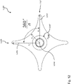
- the foundation 12 shows a top view of an embodiment of a foundation 1230 for supporting a tower, eg tower 102.
- the foundation 1230 includes a first arm 1242, which extends up to a maximum radial distance r 1 from a center point 1246 of a tower erection area 1247 of the foundation 1230 in a first direction 1243 extends.
- the foundation 1230 includes a second arm 1244 which extends up to a maximum radial distance r 1 ′ from the center point 1246 of the tower erection area 1247 of the foundation 1230 in a second direction 1245 .
- the foundation 1230 extends between the first arm 1242 and the second arm 1244 at least up to a minimum radial distance r m from the center point 1246 of the tower erection area 1247 of the foundation 1230.
- the minimum radial distance r m is at least 25% and at most 70%. the maximum radial distance r 1 of the first arm 1242.
- the shape of the foundation 1230 with the first arm 1242, the second arm 1244 and the transition area over which the foundation extends from the first arm 1242 to the second arm 1242 over the minimum radial distance r m can be used to better introduce force into the foundation 1230 or a more even force distribution in the foundation 1230 contribute.
- a load on the first arm 1242 and a load on the second arm 1244 can be reduced and distributed over the transition area by means of the transition area, which is spanned over the minimum radial distance r m .
- a load on the The first or second arm 1242, 1244, or the foundation 1230 in general, may be created by guying, such as a first guying structure acting on the first arm 1242 and a second guying structure acting on the second arm 1244.
- a load on the foundation 1230 can also result from the gravity of the tower which is arranged on the erection area 1247 of the foundation 1230 .
- the foundation 1230 shows the foundation 1230 with an equal radial distance r 1 and r 1 '.
- the maximum radial distance r 1 from the first arm 1242 may differ by less than 10% from the maximum radial distance r 1 ' from the second arm 1244 distinguish.
- a difference in radii may be manufacturing related or considered for better or different, such as asymmetric force distribution in foundation 1230.
- Figure 12 shows the foundation 1230 with a total of four arms oriented at 90° to each other. Between each arm, the foundation 1230 extends the minimum radial distance r m . Other embodiments are not limited to four arms, the radii shown, or a symmetrical shape. Other embodiments of foundations comprise at least three or more arms, with an equal angle between center axes of each two adjacent arms in a plan view. If a foundation has n arms, the angle between the arms is, for example, 360 ° n .
- the foundation extends from the first arm over the minimum radial distance to the second arm and from the second arm over the minimum radial distance to the third arm
- a distribution of forces in the foundation can also be be symmetrical
- a tower can be braced with different bracing radii.
- Figure 12 shows the foundation 1230 extending from the first arm to the second arm with a curve.
- the curvature between the first arm 1242 and the second arm 1244 can be described by an arc of a circle.
- the arc of a circle can open up refer to a circle having its center point between the first arm 1242 and the second arm 1244.
- the center of the circle may lie on an axis that includes the distance from the center 1246 of a tower erection area 1247 to the minimum radial distance r m of the foundation 1230 .
- the base 1230 has a curvature in an outer contour in plan view between the first and the second arm 1242, 1244 with a maximum deviation of 10% from a constant curvature.
- the curvature with a maximum deviation of 10% can be, for example, at least 10%, at least 20%, at least 30%, at least 40%, at least 50% or at least 60% of the outer contour (e.g. in a middle) between the first and the second arm.
- the outer contour of the foundation 1230 between the first arm 1242 and the second arm 1244 can be elliptical, oval, concave, convex, parabolic, triangular, polygonal, or otherwise shaped so that the foundation 1230 has a minimum radial distance r m between the having first and second arms.
- Embodiments of tower structures or foundations can be combined with one another as desired, e.g.
- Exemplary embodiments of tower structures, foundations or bracing can be used for wind turbines.
- a wind turbine includes, for example, the tower structure 100, 600, 700, 800, 900, 1000 or 1100 and/or the foundation 1030, 1031, 1130 or 1230.
- the wind turbine 1350 comprises a tower 1302 and a nacelle 1352 with a hub 1355 and a connected rotor 1354.
- the rotor diameter is 100m or more.
- the hub height is 120m or more.
- the wind energy installation 1350 can be deflected in the direction of the ground with guying structures 1306a and/or 1306b, e.g. via deflection structures.
- Guy structures such as 1306a can be deflected at outer force deflection areas of the foundation 1330.
- guy structures such as 1306b may be attached to pad foundations outside of foundation 1330.
- the foundation radius is 10-30m depending on the foundation shape.
- Wind turbines include tubular steel towers, for example.
- a wind turbine or a tower structure that includes efficient guying according to one of the concepts described above can have undivided tower sections.
- the bending stress in the support structure of wind turbines with large hub heights, such as >140m, can be reduced by up to 50%, for example, using cable guying.
- the material used for the supporting structures can also be reduced by up to 30%, for example.
- the tower base diameter could be designed within the transport frame conditions of, for example, 4.40 m.
- a guy height on the tower 1302 is at least 10-120 m or 20-120 m above the ground.
- a maximum guy height results from the hub height of the wind energy installation 1350 minus the rotor radius.
- additional guying levels can be located underneath.
- exemplary embodiments mentioned are not limited to an application for wind turbines, but can relate to other applications such as electricity masts, wind measuring masts, sailing masts, chimneys or towers in general.
- Exemplary embodiments of tower structures and foundations can be used, for example, for towers higher than 50m, higher than 100m, higher than 140m, higher than 160m or higher than 180m.
- FIG. 1 Further exemplary embodiments can relate to guying devices and their anchoring devices, which are aligned beneath the ground. Tower bending moments that occur can be dissipated via the guying devices into the ground or into the foundation.
- the anchoring devices of the tower guying devices can be independent of the actual tower foundation or the Acting forces can be deflected into a further anchoring device located below the tower foundation.
- the anchoring means may be part of the foundation.
- Guying can be done from one guying area through the tower/mast to a second guying area on the ground.
- Three, four or more guying areas can be used on the floor, which have a mutual angle of 120°, 90° or 360°/number of guying areas.
- the guying areas can either be designed separately or be part of the tower/mast foundation.
- anchoring devices located in the ground can represent a second separate foundation or an additional base receiving system below the existing tower foundation, which can absorb the tensile forces of the guy ropes.
- a second foundation can be laid under the actual foundation in order to be able to absorb tensile forces.
- the complete guying method can be viewed as a self-contained system, which can be largely independent of soil properties and topology.
- An example (e.g. example 1) relates to a tower structure comprising a tower along a vertical tower axis, and a guy rope, which extends from a first guying direction to a deflection structure on or in the tower and from the deflection structure in a second guying direction towards the ground extends, wherein the first guying direction differs from the second guying direction, wherein the first guying direction and the second guying direction form an angle of less than 180° in a plan view, wherein the tower axis lies outside of an area defined by the guying cable between the first guying direction and the second guying direction is limited.
- a further example (e.g. example 2) relates to a previous example (e.g. example 2), wherein the baffle structure is connected to a tower wall of the tower in such a way that a force transmitted from the guy rope to the deflection structure is transmitted to the tower wall.
- Example 3 Another example (e.g. Example 3) relates to a previous example (e.g. any of Examples 1-2) wherein the diversion structure has a contact surface, the guy rope resting on the contact surface.
- a further example (e.g. example 4) relates to a previous example (e.g. example 3), wherein the contact surface is formed in a groove-shaped depression on a surface of the deflection structure.
- a further example (e.g. example 5) relates to a previous example (e.g. example 3), wherein the baffle structure has a tubular portion, the contact surface being formed in the tubular portion of the baffle structure.
- Example 6 Another example (e.g. Example 6) relates to a previous example (e.g. any of Examples 3-5) wherein the contact surface of the diversion structure has a curvature with a radius of curvature, where twice the radius of curvature is greater than a minimum bending pulley diameter of the guy rope.
- Example 7 relates to a previous example (e.g. any of Examples 3-6), wherein the contact surface has a nature such that a coefficient of friction between the contact surface and the guy rope is so large that by pretensioning the guy rope or a fastening device creates a frictional connection between the deflection structure and the guy rope.
- Example 8 Another example (e.g. Example 8) relates to a previous example (e.g. any of Examples 1-7) wherein the baffle structure is located inside the tower and is connected to an inside of the tower wall.
- a further example (e.g. example 9) relates to a previous example (e.g. example 8), wherein the deflection structure comprises at least one connecting element which connects a part of the deflection structure comprising the contact surface to the inside of the tower wall.
- Another example (e.g. example 10) relates to a previous example (e.g. one of examples 8-9), wherein the tower wall has at least two openings through which the guy rope is routed from the outside to the deflection structure inside the tower.
- Example 11 Another example (e.g. Example 11) relates to a previous example (e.g. any of Examples 1-10) wherein the baffle structure is connected to the tower wall by a weld joint.
- Another example (e.g. example 12) relates to a previous example (e.g. any of examples 1-11) wherein a second guy line extending from the tower towards the ground, the guy line and the second guy line being at a distance of less than 1m attached to a foundation structure or deflected.
- Another example relates to a previous example (e.g. example 12) wherein the second guy rope extends from a third guy direction to a second anchor structure on or in the tower and from the second anchor structure in a fourth guy direction towards floor extends.
- Another example relates to a previous example (e.g. example 13) wherein a baffle assembly comprising the baffle structure and the second baffle structure and having a central open area through which the tower axis passes.
- Another example relates to a previous example (e.g. any of examples 1-14) wherein the guy rope extends from a first guy height of the tower towards the ground, with another guy rope extending from a second guy height towards Floor extends, the first guy height differs from the second guy height by more than 2m.
- Another example relates to a previous example (e.g. any of examples 1-15), wherein a baffle element which is connected to an outside of the tower wall and is arranged on the tower at a lower level than the baffle structure, wherein the guy rope extends over the deflection element in the first guy direction to the deflection structure or extends from the second guy direction of the deflection structure over the deflection element in the direction of the ground.
- a baffle element which is connected to an outside of the tower wall and is arranged on the tower at a lower level than the baffle structure, wherein the guy rope extends over the deflection element in the first guy direction to the deflection structure or extends from the second guy direction of the deflection structure over the deflection element in the direction of the ground.
- a further example (e.g. example 17) relates to a preceding example (e.g. example 16), wherein the deflection element is designed to at least partially transfer a tensile force of the guy rope into a compressive force acting on the tower.
- An example (e.g. example 18) relates to a tower structure comprising a tower along a vertical tower axis; a foundation for supporting the tower, the tower standing on the foundation, the foundation having an outer force deflection region spaced radially from the tower axis; and a first guy structure, wherein the first guy structure extends from the outer force deflection area to a part of the tower above the foundation, wherein the first guy structure or a second guy structure coupled to the first guy structure at the outer force deflection area extends from the outer force deflection area to an inner one Guying area extends below the outer Kraftumlenk Schemes, wherein a radial distance of the inner guying area from the tower axis is smaller than the radial distance of the outer Kraftumlenk Schemes.
- Another example relates to a previous example (e.g. example 18) where the inner guy line is part of the foundation.
- Another example relates to a preceding example (e.g., example 18), wherein the tower structure further comprises a second foundation at least partially underlying the first foundation and spaced from the first foundation, the inner guy line is part of the second foundation.
- Another example relates to a previous example (e.g. one of examples 18-20), wherein a compressive force transmitted from the at least first guying structure to the outer force deflection area acts on the foundation, the compressive force at the outer force deflection area having a angle to a horizontal plane perpendicular to the tower axis, the angle being at least 15° and at most 30°.
- Example 22 relates to a previous example (e.g. any of Examples 18-21) wherein the foundation has a second outer force redirection area spaced a second radial distance from the tower axis that differs from a first radial distance of the outer force deflection area differs by at least 20% of the first radial distance, with a further guy structure extending from the second outer force deflection area to a part of the tower above the foundation.
- Example 23 Another example (eg, Example 23) relates to a previous example (eg, any of Examples 18-22), wherein the first guy structure is a guy rope.
- Another example (e.g. example 24) relates to a previous example (e.g. example 23) wherein the guy line extends from the tower via the outer force redirection area to the inner guy line.
- An example (e.g. example 25) relates to a tower structure comprising a tower along a vertical tower axis; a foundation for supporting the tower, the tower standing on the foundation, the foundation having an outer force deflection area that lies outside a base of the tower; and a guy structure extending from an exterior of the tower to the outer force turning area and extending from the outer force turning area through an opening in the foundation from below the tower to a mounting structure inside the tower.
- Another example relates to a previous example (e.g. example 25) wherein the attachment structure is attached to the tower wall of the tower or to a transverse or longitudinal flange of the tower.
- Example 27 Another example (e.g., Example 27) relates to a previous example (e.g., any of Examples 25-26) wherein the guy structure is a guy rope.
- Example 28 relates to a previous example (e.g., any of Examples 25-27), wherein the guy structure includes a first guy cable extending from the outside of the tower to the outer force redirection area and a second guy cable , which extends from the outer force deflection area through the opening in the foundation to the attachment structure.
- the guy structure includes a first guy cable extending from the outside of the tower to the outer force redirection area and a second guy cable , which extends from the outer force deflection area through the opening in the foundation to the attachment structure.
- Example 29 relates to a previous example (e.g., any of Examples 25-28) wherein the foundation has an internal force deflection area, with the guy structure extending from the external force deflection area through the inner force deflection area to the attachment structure.
- Example 30 Another example (e.g. Example 30) relates to a previous example (e.g. Example 29) wherein the outer force turning area is a first radial distance from the tower axis and is located at a first depth and the inner force turning area is a second radial distance from the tower axis and is located at a second depth, the second radial distance being less than the first radial distance and the first depth being greater than the second depth.
- Another example relates to a previous example (e.g. example 30) wherein the first depth of the outer force turning area is at least 1m greater than the second depth of the inner force turning area.
- Another example (e.g. example 32) relates to a previous example (e.g. any of examples 25-31) wherein a compressive force transmitted from the guy structure to the outer force turning area acts on the foundation, the compressive force at the outer force turning area at an angle to a horizontal plane perpendicular to the axis of the tower, the angle being at least 30° and at most 60°.
- Another example (e.g. example 33) relates to a previous example (e.g. any of examples 25-32) wherein the foundation has a central cavity beneath the tower.
- a further example (e.g. example 34) relates to a previous example (e.g. example 33) wherein the central cavity forms the opening in the foundation through which the guy structure extends.
- Another example (e.g. example 35) relates to a previous example (e.g. any of examples 33-34) wherein an apparatus or plant is located in the central cavity.
- a further example (e.g. Example 36) relates to a previous example (e.g. any of Examples 33-35) wherein the central cavity is ventilated, the cavity being ventilated through a ventilation opening through the foundation or a ventilation duct beneath the foundation.
- Another example (e.g. example 37) relates to a previous example (e.g. any of examples 33-36) wherein the foundation has a further outer force redirection region spaced radially from the tower axis which differs from the radial distance of the outer Kraftumlenk Schemes differs by at least 20% of the radial distance of the outer Kraftumlenk Scheme, wherein a further guying structure extends from an outside of the tower to the other outer Kraftumlenk Scheme.
- Another example (e.g., example 38) relates to a previous example (e.g., any of examples 23, 24, or 27) wherein the outer force redirection region has a bend having a radius of curvature, twice the radius of curvature being greater than a minimum bending roller diameter of the guy rope.
- An example relates to a wind energy plant comprising a tower structure according to one of the preceding examples (e.g. example 1-38 or an example as described in the figures).
- a block, a device or a functional aspect of the device or the system can correspond to a feature, such as a method step, of the corresponding method.
- aspects described in connection with a method are also to be understood as a description of a corresponding block, element, property or functional feature of a corresponding device or system.
Abstract
Ein Beispiel eines Turmbauwerks (100) umfasst einen Turm (102) entlang einer senkrechten Turmachse (104) und ein Abspannseil (106a), das sich aus einer ersten Abspannrichtung (107a) zu einer Umlenkstruktur (210a) am oder im Turm (102) erstreckt und sich von der Umlenkstruktur (210a) in einer zweiten Abspannrichtung (108a) in Richtung Boden erstreckt, wobei sich die erste Abspannrichtung (107a) von der zweiten Abspannrichtung (108a) unterscheidet, wobei die erste Abspannrichtung (107a) und die zweite Abspannrichtung (108a) in einer Aufsicht (201) einen Winkel kleiner als 180° bilden, wobei die Turmachse (104) außerhalb eines Bereichs liegt, der von dem Abspannseil (106a) zwischen der ersten Abspannrichtung (107a) und der zweiten Abspannrichtung (108a) begrenzt wird.An example of a tower structure (100) includes a tower (102) along a vertical tower axis (104) and a guy rope (106a) that extends from a first guying direction (107a) to a deflection structure (210a) on or in the tower (102). and extends from the deflection structure (210a) in a second guying direction (108a) towards the ground, wherein the first guying direction (107a) differs from the second guying direction (108a), wherein the first guying direction (107a) and the second guying direction (108a ) form an angle of less than 180° in a top view (201), the tower axis (104) lying outside an area that is delimited by the guy rope (106a) between the first guying direction (107a) and the second guying direction (108a).
Description
Ausführungsbeispiele befassen sich mit Turmbauwerken, Fundamenten zum Tragen von Türmen und Windenergieanlagen.Exemplary embodiments deal with tower structures, foundations for supporting towers and wind turbines.
On-Shore Windenergieanlagen (WEAs) benötigen für einen wirtschaftlichen Betrieb große Nabenhöhen (z.B. > 140m) und große Rotordurchmesser (z.B. >130m). Für große Nabenhöhen und große Rotordurchmesser werden für die Türme der WEAs große Turmfußdurchmesser gefordert, um die auftretenden Biegemomente aufnehmen zu können. Transportrahmenbedingungen, wie z.B. Durchfahrtshöhen an Land beschränken allerdings die maximal möglichen Durchmesser für Turmsektionen auf 4,4 m.On-shore wind turbines (WEAs) require large hub heights (e.g. > 140m) and large rotor diameters (e.g. > 130m) for economic operation. For large hub heights and large rotor diameters, large tower base diameters are required for the towers of the wind turbines in order to be able to absorb the bending moments that occur. However, general transport conditions, such as clearance heights on land, limit the maximum possible diameter for tower sections to 4.4 m.
Eine Möglichkeit zum Errichten von WEAs mit großen Nabenhöhen bzw. Rotordurchmessern bieten Abspannungen. Abspannungen werden am Turm befestigt und erstrecken sich von einer bestimmten Turmhöhe der WEA bis zum Boden. Eine effektive Abspannung erfordert allerdings einen hohen Platzbedarf am Boden, da die für die Abspannung benötigten Abspannseile üblicherweise mit einem Abstand von 40-100m am Boden um die WEA gespannt werden. Ein größerer Platzbedarf am Boden ist allerdings mit höheren Kosten für die Flächensicherung und höheren Anforderungen an die Geländetopologie verbunden.An option for erecting wind turbines with large hub heights or rotor diameters is provided by guy lines. Guy lines are attached to the tower and extend from a certain tower height of the wind turbine down to the ground. However, effective guying requires a lot of space on the ground, since the guy ropes required for the guying are usually stretched around the wind turbines at a distance of 40-100m on the ground. However, a larger space requirement on the ground is associated with higher costs for securing the area and higher requirements for the topology of the terrain.
Ein anderer Aspekt von Abspannungen betrifft die Befestigung der Abspannseile am Turm. Aufgrund der Befestigung wirken sich die hohen Lasten, die über die Abspannseile auf den Turm übertragen werden, oftmals negativ auf das Beulverhalten der Turmstruktur aus.Another aspect of guy lines relates to the attachment of the guy lines to the tower. Due to the attachment, the high loads that are transferred to the tower via the guy ropes often have a negative effect on the buckling behavior of the tower structure.
Es besteht ein Bedarf für Turmbauwerke oder für Komponenten von Turmbauwerken eine verbesserte Abspannung zu schaffen, eine verbesserte Lastübertragung auf das Turmbauwerk zu erreichen und/oder eine Reduktion des Platzbedarfs des Turmbauwerks zu ermöglichen.There is a need for tower structures or for components of tower structures to provide improved bracing, to achieve improved load transfer to the tower structure and/or to enable a reduction in the space required by the tower structure.
Dieser Bedarf könnte durch den Gegenstand einer der vorliegenden Ansprüche gedeckt werden.This need could be met by the subject matter of any of the present claims.
In einem Ausführungsbeispiel umfasst ein Turmbauwerk einen Turm entlang einer senkrechten Turmachse und ein Abspannseil, das sich aus einer ersten Abspannrichtung zu einer Umlenkstruktur am oder im Turm erstreckt und sich von der Umlenkstruktur in einer zweiten Abspannrichtung in Richtung Boden erstreckt, wobei sich die erste Abspannrichtung von der zweiten Abspannrichtung unterscheidet, wobei die erste Abspannrichtung und die zweite Abspannrichtung in einer Aufsicht einen Winkel kleiner als 180° bilden, wobei die Turmachse außerhalb eines Bereichs liegt, der von dem Abspannseil zwischen der ersten Abspannrichtung und der zweiten Abspannrichtung begrenzt wird.In one embodiment, a tower structure comprises a tower along a vertical tower axis and a guy rope that extends from a first guying direction to a deflection structure on or in the tower and extends from the deflection structure in a second guying direction towards the ground, with the first guying direction extending from the second guying direction, with the first guying direction and the second guying direction forming an angle of less than 180° in a top view, with the tower axis lying outside an area that is delimited by the guy rope between the first guying direction and the second guying direction.
In einem Ausführungsbeispiel umfasst ein Turmbauwerk einen Turm entlang einer senkrechten Turmachse und ein Fundament zum Tragen des Turmes, wobei der Turm auf dem Fundament steht, wobei das Fundament einen äußeren Kraftumlenkbereich aufweist, der einen radialen Abstand von der Turmachse aufweist. Ferner umfasst das Turmbauwerk eine erste Abspannstruktur, wobei sich die erste Abspannstruktur von dem äußeren Kraftumlenkbereich zu einem Teil des Turms oberhalb des Fundaments erstreckt, wobei sich die erste Abspannstruktur oder eine mit der ersten Abspannstruktur an dem äußeren Kraftumlenkbereich gekoppelte, zweite Abspannstruktur von dem äußeren Kraftumlenkbereich zu einem inneren Abspannbereich unterhalb des äußeren Kraftumlenkbereichs erstreckt, wobei ein radialer Abstand des inneren Abspannbereichs von der Turmachse kleiner ist als der radiale Abstand des äußeren Kraftumlenkbereichs.In one embodiment, a tower structure includes a tower along a vertical tower axis and a foundation for supporting the tower, the tower standing on the foundation, the foundation having an outer force deflection area radially spaced from the tower axis. The tower structure also includes a first guy structure, the first guy structure extending from the outer force deflection area to a part of the tower above the foundation, the first guy structure or a second guy structure coupled to the first guy structure at the outer force deflection area extending from the outer force deflection area to an inner guying area below the outer force deflection area, wherein a radial distance of the inner guying area from the tower axis is smaller than the radial distance of the outer force deflection area.
In einem Ausführungsbeispiel umfasst ein Turmbauwerk einen Turm entlang einer senkrechten Turmachse und ein Fundament zum Tragen des Turmes, wobei der Turm auf dem Fundament steht, wobei das Fundament einen äußeren Kraftumlenkbereich aufweist, der außerhalb einer Grundfläche des Turms liegt. Ferner umfasst das Turmbauwerk eine Abspannstruktur, die sich von einer Außenseite des Turms zu dem äußeren Kraftumlenkbereich erstreckt und von dem äußeren Kraftumlenkbereich durch eine Öffnung im Fundament von unterhalb des Turms zu einer Befestigungsstruktur im Turminneren erstreckt.In an exemplary embodiment, a tower structure comprises a tower along a vertical tower axis and a foundation for supporting the tower, the tower standing on the foundation, the foundation having an outer force deflection area which is outside a base of the tower. The tower structure also includes a guying structure that extends from an outside of the tower to the outer force deflection area and from the outer force deflection area through an opening in the foundation from underneath the tower to a fastening structure inside the tower.
Einige Ausführungsbeispiele beziehen sich auf Fundamente zum Tragen eines Turmes. Das Fundament umfasst einen ersten Arm, der sich bis zu einem maximalen radialen Abstand von einem Mittelpunkt eines Turmaufstellbereichs des Fundaments in eine erste Richtung erstreckt. Ferner umfasst das Fundament einen zweiten Arm, der sich bis zu einem maximalen radialen Abstand von einem Mittelpunkt des Turmaufstellbereichs des Fundaments in eine zweite Richtung erstreckt, wobei sich das Fundament zwischen dem ersten Arm und dem zweiten Arm zumindest bis zu einem minimalen radialen Abstand von dem Mittelpunkt des Turmaufstellbereichs des Fundaments erstreckt, wobei der minimale radiale Abstand mindestens 25% und maximal 70% des maximalen radialen Abstands des ersten Arms beträgt.Some embodiments relate to foundations for supporting a tower. The foundation includes a first arm extending a maximum radial distance from a midpoint of a tower deployment area of the foundation in a first direction. The foundation further includes a second arm extending in a second direction to a maximum radial distance from a center point of the tower erection area of the foundation, the foundation extending between the first arm and the second arm at least to a minimum radial distance from the Center of the tower erection area of the foundation extends, the minimum radial distance being at least 25% and a maximum of 70% of the maximum radial distance of the first arm.
Weitere Ausführungsbeispiele beziehen sich auf Windenergieanlagen, die ein Turmbauwerk und/oder ein Fundament gemäß einem der oben genannten Ausführungsbeispiele umfassen.Further exemplary embodiments relate to wind energy installations which comprise a tower structure and/or a foundation according to one of the exemplary embodiments mentioned above.
Einige Beispiele von Vorrichtungen und/oder Verfahren werden nachfolgend bezugnehmend auf die beiliegenden Figuren lediglich beispielhaft näher erläutert. Es zeigen:
- Fig. 1
- ein Ausführungsbeispiel eines Turmbauwerks;
- Fig. 2
- ein Beispiel für eine Aufsicht eines Turmbauwerks;
- Fig. 3
- ein Beispiel für eine Umlenkstruktur;
- Fig. 4
- ein weiteres Beispiel für eine Umlenkstruktur;
- Fig. 5
- ein Beispiel für eine Aufsicht eines Turmbauwerks mit einer Umlenkanordnung;
- Fig. 6
- ein weiteres Ausführungsbeispiel eines Turmbauwerks;
- Fig. 7
- ein Ausführungsbeispiel eines Turmbauwerks mit Umlenkelementen;
- Fig. 8
- ein Ausführungsbeispiel eines Turmbauwerks mit unterschiedlichen Abspannhöhen;
- Fig. 9
- ein Ausführungsbeispiel eines Turmbauwerks mit unterschiedlichen Abspannradien;
- Fig. 10
- ein Ausführungsbeispiels eines Turmbauwerks mit einem äußeren Kraftumlenkbereich;
- Fig. 11
- ein weiteres Ausführungsbeispiel eines Turmbauwerks mit einem äußeren Kraftumlenkbereich;
- Fig. 12
- ein Ausführungsbeispiel eines Fundaments; und
- Fig. 13
- ein Ausführungsbeispiel einer Windenergieanlage.
- 1
- an embodiment of a tower structure;
- 2
- an example of a top view of a tower structure;
- 3
- an example of a deflection structure;
- 4
- another example of a deflection structure;
- figure 5
- an example of a top view of a tower structure with a deflection arrangement;
- 6
- another embodiment of a tower structure;
- 7
- an embodiment of a tower structure with deflection elements;
- 8
- an embodiment of a tower structure with different guy heights;
- 9
- an embodiment of a tower structure with different guy radii;
- 10
- an embodiment of a tower structure with an outer Kraftumlenkbereich;
- 11
- a further exemplary embodiment of a tower structure with an outer force deflection area;
- 12
- an embodiment of a foundation; and
- 13
- an embodiment of a wind turbine.
Einige Beispiele werden nun ausführlicher Bezug nehmend auf die beiliegenden Figuren beschrieben. Weitere mögliche Beispiele sind jedoch nicht auf die Merkmale dieser detailliert beschriebenen Ausführungsformen beschränkt. Diese können Modifikationen der Merkmale sowie Entsprechungen und Alternativen zu den Merkmalen aufweisen. Ferner soll die Terminologie, die hierin zum Beschreiben bestimmter Beispiele verwendet wird, nicht einschränkend für weitere mögliche Beispiele sein.Some examples will now be described in more detail with reference to the accompanying figures. However, other possible examples are not limited to the features of these detailed described embodiments. These may include modifications of the features, as well as equivalents and alternatives to the features. Furthermore, the terminology used herein to describe particular examples is not intended to be limiting of other possible examples.
Gleiche oder ähnliche Bezugszeichen beziehen sich in der gesamten Beschreibung der Figuren auf gleiche oder ähnliche Elemente beziehungsweise Merkmale, die jeweils identisch oder auch in abgewandelter Form implementiert sein können, während sie die gleiche oder eine ähnliche Funktion bereitstellen. In den Figuren können ferner die Stärken von Linien, Schichten und/oder Bereichen zur Verdeutlichung übertrieben sein.Throughout the description of the figures, the same or similar reference symbols refer to the same or similar elements or features, which can each be implemented identically or in a modified form, while providing the same or a similar function. Also, in the figures, the thicknesses of lines, layers, and/or areas may be exaggerated for clarity.
Wenn zwei Elemente A und B unter Verwendung eines "oder" kombiniert werden, ist dies so zu verstehen, dass alle möglichen Kombinationen offenbart sind, d. h. nur A, nur B sowie A und B, sofern nicht im Einzelfall ausdrücklich anders definiert. Als alternative Formulierung für die gleichen Kombinationen kann "zumindest eines von A und B" oder "A und/oder B" verwendet werden. Das gilt Äquivalent für Kombinationen von mehr als zwei Elementen.When two elements A and B are combined using an "or", it is to be understood that all possible combinations are disclosed, i. H. only A, only B and A and B, unless expressly defined otherwise in individual cases. As alternative wording for the same combinations, "at least one of A and B" or "A and/or B" can be used. The equivalent applies to combinations of more than two elements.
Wenn eine Singularform, z. B. "ein, eine" und "der, die, das" verwendet wird und die Verwendung nur eines einzelnen Elements weder explizit noch implizit als verpflichtend definiert ist, können weitere Beispiele auch mehrere Elemente verwenden, um die gleiche Funktion zu implementieren. Wenn eine Funktion im Folgenden als unter Verwendung mehrerer Elemente implementiert beschrieben ist, können weitere Beispiele die gleiche Funktion unter Verwendung eines einzelnen Elements oder einer einzelnen Verarbeitungsentität implementieren. Es versteht sich weiterhin, dass die Begriffe "umfasst", "umfassend", "aufweist" und/oder "aufweisend" bei deren Gebrauch das Vorhandensein der angegebenen Merkmale, Ganzzahlen, Schritte, Operationen, Prozesse, Elemente, Komponenten und/oder einer Gruppe derselben beschreiben, dabei aber nicht das Vorhandensein oder das Hinzufügen eines oder mehrerer anderer Merkmale, Ganzzahlen, Schritte, Operationen, Prozesse, Elemente, Komponenten und/einer Gruppe derselben ausschließen.If a singular form, e.g. For example, when "a, an" and "the" are used, and use of only a single element is not explicitly or implicitly required, other examples may use multiple elements to implement the same function. Where a function is described below as being implemented using multiple elements, other examples may implement the same function using a single element or processing entity. It is further understood that the terms "comprises," "comprising," "comprises," and/or "comprising" when used imply the presence of the specified feature, integer, step, operation, process, element, component, and/or group describe the same, but does not exclude the presence or addition of any other feature, integer, step, operation, process, element, component and/or group thereof.
Einige Ausführungsbeispiele beziehen sich auf Turmbauwerke. Ein Turmbauwerk umfasst einen Turm entlang einer senkrechten Turmachse und ein Abspannseil, das sich aus einer ersten Abspannrichtung zu einer Umlenkstruktur am oder im Turm erstreckt und sich von der Umlenkstruktur in einer zweiten Abspannrichtung in Richtung Boden erstreckt. Die erste Abspannrichtung unterscheidet sich von der zweiten Abspannrichtung. Die erste Abspannrichtung und die zweite Abspannrichtung bilden in einer Aufsicht einen Winkel kleiner als 180°. Die Turmachse liegt außerhalb eines Bereichs, der von dem Abspannseil zwischen der ersten Abspannrichtung und der zweiten Abspannrichtung begrenzt wird.Some exemplary embodiments relate to tower structures. A tower structure includes a tower along a vertical tower axis and a guy rope that extends from a first guy direction to a deflection structure on or in the tower and extends from the deflection structure in a second guy direction towards the ground. The first guying direction differs from the second guying direction. The first guying direction and the second guying direction form an angle of less than 180° in a plan view. The tower axis lies outside of an area that is delimited by the guy rope between the first guying direction and the second guying direction.
Durch das Abspannseil kann eine Abspannung des Turms erfolgen, sodass eine Biegebeanspruchung des Turms reduziert werden kann. Zum Beispiel kann das Abspannseil über eine Vorrichtung im Boden vorgespannt werden, sodass eine von dem Abspannseil aufgenommene Zugkraft in die Vorrichtung im Boden eingeleitet werden kann. Das Abspannseil kann über die Umlenkstruktur mit dem Turm verbunden werden. Die Umlenkstruktur kann das Abspannseil von der ersten Abspannrichtung in die zweite Abspannrichtung umlenken. Durch die Umlenkung des Abspannseils am oder im Turm kann über das Abspannseil eine Lasteinleitung in den Turm großflächiger erfolgen. Durch die flächige Lasteinleitung kann der Turm gleichmäßiger beansprucht werden. Die Lage der Turmachse außerhalb des Bereichs, der von dem Abspannseil zwischen der ersten Abspannrichtung und der zweiten Abspannrichtung begrenzt wird, kann eine zur Turmachse exzentrische Umlenkung des Abspannseils ermöglichen. Eine exzentrische Umlenkung kann eine effizientere Krafteinleitung in den Turm bewirken. Nach diesem Konzept brauchen für eine effiziente Abspannung des Turms die erste Abspannrichtung und die zweite Abspannrichtung nicht zur Turmachse zeigen. Durch die effizientere Abspannung des Turmes könnte der Turm innerhalb der Transportrahmenbedingungen von z.B. 4,40 m ausgeführt werden. Beispielsweise kann eine zusätzliche Unterteilung von Turmsektionen vermieden werden.The guy rope can be used to brace the tower, so that a bending stress on the tower can be reduced. For example, the guy rope can be pretensioned via a device in the ground, so that a tensile force absorbed by the guy rope can be introduced into the device in the ground. The guy rope can be connected to the tower via the deflection structure. The deflection structure can deflect the guy rope from the first guy direction to the second guy direction. Through the deflection of the guy rope on or in the tower can take place via the guy rope load introduction into the tower over a large area. The tower can be stressed more evenly due to the areal load application. The position of the tower axis outside of the area delimited by the guy rope between the first guying direction and the second guying direction can enable the guy rope to be deflected eccentrically to the tower axis. An eccentric deflection can bring about a more efficient introduction of force into the tower. According to this concept, for efficient guying of the tower, the first guying direction and the second guying direction do not have to point to the tower axis. Due to the more efficient bracing of the tower, the tower could be designed within the transport framework of, for example, 4.40 m. For example, an additional subdivision of tower sections can be avoided.
Die Umlenkstruktur kann derart ausgebildet sein, dass das Abspannseil von der ersten in die zweite Abspannrichtung umgelenkt werden kann. Die Umlenkstruktur kann eine von dem Abspannseil übertragene Kraft als Druckkraft aufnehmen und in den Turm einleiten, wenn sie beispielsweise im Turminneren angeordnet ist. Ein Abschnitt des Abspannseil kann mit der Umlenkstruktur gekoppelt sein. Zum Beispiel kann ein Abschnitt des Abspannseils auf der Umlenkstruktur aufliegen oder ein Abschnitt des Abspannseils kann sich durch die Umlenkstruktur erstrecken. Die Umlenkstruktur kann z.B. aus Stahl sein und derart mit dem Turm verbunden, z.B. verschweißt oder verschraubt sein, dass eine flächige Lasteinleitung in den Turm erfolgen kann. Die Umlenkstruktur kann derart ausgebildet und mit dem Turm verbunden sein, dass die erste und zweite Abspannrichtung exzentrisch zur Turmachse ausgerichtet sein können.The deflection structure can be designed in such a way that the guy rope can be deflected from the first to the second guying direction. The deflection structure can absorb a force transmitted by the guy rope as a compressive force and can introduce it into the tower if it is arranged inside the tower, for example. A portion of the guy rope may be coupled to the deflection structure. For example, a portion of the guy line may rest on the baffle structure, or a portion of the guy line may extend through the baffle structure. The deflection structure can be made of steel, for example, and connected to the tower, e.g. welded or bolted, in such a way that a load can be introduced over the entire surface of the tower. The deflection structure can be designed and connected to the tower in such a way that the first and second guying direction can be aligned eccentrically to the tower axis.
Die Umlenkstruktur kann am oder im Turm ausgebildet sein. Zum Beispiel kann die Umlenkstruktur mit einer Innenseite der Turmwand oder einer Außenseite der Turmwand gekoppelt sein. Durch die Anordnung der Umlenkstruktur im Turminnern kann diese beispielsweise vor äußeren Einflüssen, z.B. Nässe, geschützt sein. Durch die Verbindung der Umlenkstruktur an einer Turmaußenwand kann die Umlenkung des Abspannseils mit einer größeren Entfernung von der Turmachse erfolgen und/oder eine Durchführung des Abspannseils durch die Turmwand kann vermieden werden. Die Krafteinwirkung auf die Turmwand kann sich je nach Anordnung der Umlenkstruktur relativ zur Turmachse oder zur Turmwand, unterscheiden.The deflection structure can be formed on or in the tower. For example, the baffle structure may be coupled to an inside of the tower wall or an outside of the tower wall. By arranging the deflection structure inside the tower, it can be protected, for example, from external influences, such as moisture. By connecting the deflection structure to an outer tower wall, the deflection of the guy rope can take place at a greater distance from the tower axis and/or a passage of the guy rope through the tower wall can be avoided. The force acting on the tower wall can differ depending on the arrangement of the deflection structure relative to the tower axis or to the tower wall.
Die Aufsicht kann beispielsweise ein Querschnitt senkrecht zur Turmachse sein oder im Allgemeinen eine Darstellung umfassen, die im Wesentlichen senkrecht zur Turmachse verläuft.For example, the top view can be a cross-section perpendicular to the axis of the tower or, in general, can include a representation that runs essentially perpendicular to the axis of the tower.
Die erste Abspannrichtung und die zweite Abspannrichtung können beispielsweise einen Winkel größer als 30°, 40°, 60°, 90°, 120° oder 150° einschließen. Beispielsweise können die erste Abspannrichtung und die zweite Abspannrichtung in einer Aufsicht einen Winkel größer als 10° (oder größer als 30°, 40°, 60°, 90°, 120° oder 150°) bilden. Der Abschnitt des Abspannseils, der mit der Umlenkstruktur gekoppelt ist und der Abschnitt des Abspannseils, der sich außerhalb der Umlenkstruktur in die erste und zweite Abspannrichtung erstreckt, können zusammen einen Bereich einschließen, der die Turmachse nicht umfasst. Die erste Abspannrichtung und die zweite Abspannrichtung können in Richtung Boden ausgerichtet sein. Im Allgemeinen kann die erste und die zweite Abspannrichtung in Richtung eines Bereichs zeigen, der sich unterhalb der Umlenkstruktur im Hinblick auf die Turmachse befindet. Der Bereich unterhalb der Umlenkstruktur kann z.B. eine Turmsektion unterhalb der Umlenkstruktur, den Turmfuß, das Fundament, die Oberfläche unmittelbar oberhalb des Bodens oder einen Teil des Bodens umfassen.The first guying direction and the second guying direction can, for example, enclose an angle greater than 30°, 40°, 60°, 90°, 120° or 150°. For example, the first guying direction and the second guying direction can form an angle greater than 10° (or greater than 30°, 40°, 60°, 90°, 120° or 150°) in a plan view. The section of the guy rope that is coupled to the deflection structure and the section of the guy rope that extends outside of the deflection structure in the first and second guy directions can together enclose an area that does not include the tower axis. The first guying direction and the second guying direction can be aligned towards the ground. In general, the first and the second guying direction can point in the direction of an area that is located below the deflection structure with respect to the tower axis. The area below the baffle structure may include, for example, a tower section below the baffle structure, the tower base, the foundation, the surface just above the ground, or a portion of the ground.
Beispielsweise kann die erste Abspannrichtung auf einen ersten Punkt am Boden gerichtet sein (und/oder von dem ersten Punkt zu der Umlenkstruktur gerichtet sein) und die zweite Abspannrichtung kann auf einen zweiten Punkt am Boden gerichtet sein (und/oder von dem zweiten Punkt zu der Umlenkstruktur gerichtet sein). Der erste Punkt am Boden und/oder der zweite Punkt am Boden haben beispielsweise einen Abstand von der Turmwand von mehr als 2 m (oder mehr als 5 m oder mehr als 10 m). Der Abstand von der Turmwand des ersten Punkts am Boden kann sich um weniger als 1m oder weniger als 50% von dem Abstand von der Turmwand des zweiten Punkts am Boden unterscheiden.For example, the first guying direction can be directed to a first point on the ground (and/or be directed from the first point to the deflection structure) and the second guying direction can be directed to a second point on the ground (and/or from the second point to the deflection structure be directed). For example, the first point on the ground and/or the second point on the ground are at a distance from the tower wall of more than 2 m (or more than 5 m or more than 10 m). The distance from the tower wall of the first point on the ground can differ by less than 1m or less than 50% from the distance from the tower wall of the second point on the ground.
Das Abspannseil kann eine beliebige Seilstruktur sein, die es ermöglicht, eine Zugkraft aufzunehmen und auf die Umlenkstruktur zu übertragen. Beispielsweise ist das Abspannseil ein Stahlseil. Das Abspannseil kann sich bis zum Boden (z.B. zu einer Verankerung am Fundament) erstrecken oder Teil einer mehrteiligen Abspannstruktur sein, die neben dem Abspannseil ein oder mehrere Seilabschnitte, ein oder mehrere Ketten oder ein oder mehrere Stangen umfasst. Im Vergleich zu einer einteiligen Abspannstruktur, die nur das Abspannseil umfasst, kann z.B. ein mehrteilige Abspannstruktur Abschnitte mit unterschiedlichen Durchmessern, Formen, Strukturen oder Materialien umfassen. Das Abspannseil ist beispielsweise zur Ausrichtung in die erste und zweite Abspannrichtung um die Umlenkstruktur gebogen.The guy rope can be any rope structure that makes it possible to absorb a tensile force and transfer it to the deflection structure. For example, the guy rope is a steel cable. The guy rope can extend to the ground (eg to an anchorage on the foundation) or be part of a multi-part guy structure which, in addition to the guy rope, comprises one or more rope sections, one or more chains or one or more rods. Compared to a one-piece guy structure that only includes the guy rope, a multi-piece guy structure can have sections with different diameters, include shapes, structures or materials. The guy rope is bent around the deflection structure, for example, for alignment in the first and second guy direction.
Der Turm kann eine beliebig hohe Einrichtung sein, die sich vom Boden in eine Höhe erstreckt. Der Turm hat beispielsweise eine vielfach größere Höhe als Durchmesser. Zur Reduktion von Torsions- und Biegemomenten am Turm, kann der Turm mittels der Abspannseile gespannt werden. Zum Beispiel kann der Turm abhängig von der Höhe mehrere Turmsektionen haben. Der Turm kann beispielsweise mehr als 50m, mehr als 80m, mehr als 100m, mehr als 120m, mehr als 140m, mehr als 160m oder mehr als 180m hoch sein. Der Turm kann an unterschiedlichen Höhen abgespannt werden. Zum Beispiel kann der Turm aus Stahl gefertigte Turmsektionen umfassen.The tower can be any high facility that extends from the ground to a height. The tower, for example, has a height that is many times greater than its diameter. To reduce torsional and bending moments on the tower, the tower can be tensioned using the guy ropes. For example, depending on the height, the tower can have several tower sections. For example, the tower may be more than 50m, more than 80m, more than 100m, more than 120m, more than 140m, more than 160m or more than 180m high. The tower can be braced at different heights. For example, the tower may include tower sections made of steel.
Die Turmachse kann senkrecht z.B. zu einem Boden, einem Fundament des Turms, oder zu einer Fläche zum Aufstellen des Turmes sein. Die senkrechte Turmachse kann parallel zur Richtung der Schwerkraft sein. Die senkrechte Turmachse kann beispielsweise von der Richtung der Schwerkraft um maximal 5mm pro Meter der Turmhöhe (ohne Berücksichtigung einer Schräglage des Fundaments) oder maximal 8mm pro Meter der Turmhöhe (mit Berücksichtigung einer Schräglage des Fundaments) abweichen.The tower axis may be perpendicular to, for example, a floor, a foundation of the tower, or a surface for erecting the tower. The vertical tower axis can be parallel to the direction of gravity. For example, the vertical tower axis can deviate from the direction of gravity by a maximum of 5mm per meter of tower height (without taking into account an inclined position of the foundation) or a maximum of 8mm per meter of tower height (taking into account an inclined position of the foundation).
Für eine effektive Abspannung kann das Turmbauwerk mehr als ein Abspannseil und mehr als eine Umlenkstruktur umfassen. Beispielsweise kann ein Turmbauwerk zwei, drei oder mehr Abspannseile und/oder Umlenkstrukturen umfassen. Abspannseile und Umlenkstrukturen können am Turm derart verteilt sein, dass der Turm möglichst gleichmäßig belastet werden kann. Beispielsweise können Abspannseile und Umlenkstrukturen symmetrisch oder mit einem gleichen Winkel hinsichtlich der Turmachse oder zueinander angeordnet sein. Gemäß einem Beispiel kann ein Turmbauwerk genauso viele Abspannseile wie Umlenkstrukturen, mehr Abspannseile als Umlenkstrukturen oder weniger Abspannseile als Umlenkstrukturen umfassen.For effective guying, the tower structure can include more than one guy rope and more than one deflection structure. For example, a tower structure can include two, three or more guy ropes and/or deflection structures. Guy ropes and deflection structures can be distributed on the tower in such a way that the tower can be loaded as evenly as possible. For example, guy ropes and deflection structures can be arranged symmetrically or at the same angle with respect to the tower axis or to one another. According to one example, a tower structure may include as many guy wires as turning structures, more guy wires than turning structures, or fewer guy wires than turning structures.
Der zu errichtende Turm umfasst beispielsweise eine Mehrzahl von übereinander angeordneten Turmsektionen, die einteilig oder mehrteilig ausgebildet sein können. Beispielsweise können die Turmsektion einteilig ausgebildet sein, wenn sie innerhalb der Transportrahmenbedingungen von z.B. 4,4m gefertigt werden. Z.B. kann der Turm oder alle Turmsektionen des Turms einen maximalen Durchmesser von maximal 4,5m (oder maximal 4m oder maximal 3,5m) aufweisen, beispielsweise bei einer Höhe von mehr als 120m (oder mehr als 140m, mehr als 160m oder mehr als 180m). Die Turmwand oder Schale des Turms oder der Turmsektion kann beispielsweise zylindermantelförmig oder kegelstumpfmantelförmig sein und/oder eine Stahlschale oder Stahlblechschale sein. Die Turmwand oder die Turmschale kann beispielsweise eine Dicke von mehr als 20 mm, 30 mm, 40 mm oder mehr aufweisen.The tower to be erected comprises, for example, a plurality of tower sections arranged one above the other, which can be designed in one piece or in multiple pieces. For example, the tower section can be designed in one piece if they are manufactured within the transport frame conditions of, for example, 4.4 m. E.g. the tower or all tower sections of the tower may have a maximum diameter of maximum 4.5m (or maximum 4m or maximum 3.5m), for example at a height of more than 120m (or more than 140m, more than 160m or more than 180m). The tower wall or shell of the tower or the tower section can be, for example, in the shape of a cylinder jacket or a truncated cone jacket and/or a steel shell or sheet steel shell. The tower wall or the tower shell can have a thickness of more than 20 mm, 30 mm, 40 mm or more, for example.
Beispielsweise können die erste Abspannrichtung und die zweite Abspannrichtung in einer Aufsicht einen Winkel kleiner als 180° (oder kleiner als 160°, kleiner als 130°, kleiner als 100° oder kleiner als 80°) und/oder größer als 10° (oder größer als 20°, größer als 30°, größer als 40°, größer als 60°, größer als 90°, größer als 120° oder größer als 150°) bilden.For example, the first guy direction and the second guy direction in a top view can form an angle of less than 180° (or less than 160°, less than 130°, less than 100° or less than 80°) and/or greater than 10° (or greater than 20°, greater than 30°, greater than 40°, greater than 60°, greater than 90°, greater than 120° or greater than 150°).
Wie beispielhaft in der Aufsicht 201 gezeigt ist, können auch die weiteren Abspannseile 106b-c wie das Abspannseil 106a an den entsprechenden Umlenkstrukturen 210b-c umgelenkt werden. Beispielsweise erstreckt sich das Abspannseil 106b aus einer dritten Abspannrichtung zu der Umlenkstruktur 210b am oder im Turm 102 und erstreckt sich von der Umlenkstruktur 210b in eine vierte Abspannrichtung in Richtung Boden.As shown by way of example in
In dem in
Mittels der Abspannseile 106a-c, die über die Umlenkstrukturen 210a-c umgelenkt werden, kann eine Abspannung des Turmbauwerks 100 exzentrisch zur Turmachse 104 erfolgen. Zum Beispiel brauchen die Abspannseile 106a-c nicht auf die Turmachse 104 ausgerichtet sein bzw. die erste und die zweite Abspannrichtung 107a und 108a brauchen für eine effektive Abspannung nicht zur Turmachse 104 zeigen.The
In den nachfolgenden Beschreibungen wird das Turmbauwerk 100 in Verbindung mit dem Abspannseil 106a und der Umlenkstruktur 210a näher ausgeführt. Die Ausführungen können sich dabei ebenso auf die Abspannseile 106b-c und auf die Umlenkstrukturen 210b-c beziehen. In den Ausführungen kann das Abspannseil 106a als erstes Abspannseil, die Umlenkstruktur 210a als erste Umlenkstruktur bezeichnet sein. Das Abspannseil 106b oder 106c kann als weiteres, anderes zweites oder drittes Abspannseil und die Umlenkstruktur 210b oder 210c kann als weitere, andere, zweite oder dritte Umlenkstruktur bezeichnet sein.In the following descriptions, the
Andere Ausführungsbeispiele können mehr als drei Abspannseile und Umlenkstrukturen umfassen. Falls geeignet, können andere Ausführungsbeispiele zumindest ein erstes Abspannseil 106a und eine erste Umlenkstruktur 210a gemäß der obigen Beschreibung umfassen und mit einer anderen Abspannmethode zur Abspannung des Turmbauwerks 100 kombiniert werden.Other embodiments may include more than three guy lines and diversion structures. If appropriate, other exemplary embodiments can include at least a
Weitere Einzelheiten und optionale Aspekte des Turmbauwerks 100 sind in Verbindung mit dem vorgeschlagenen Konzept oder einem oder mehreren der im Folgenden beschriebenen Beispiele beschrieben.Further details and optional aspects of the
Wie in den Beispielen in
Mittels der Umlenkstruktur 310, 410 kann das Abspannseil 106a am oder im Turm umgelenkt werden, sodass eine Abspannung des Turmbauwerks 100 ermöglicht wird. Das Abspannseil 106a kann auf der Umlenkstruktur 310, 410 derart aufgelegt werden, dass eine aufwendige Befestigung des Abspannseils 106a am oder im Turm 102 vermieden werden kann. Zum Beispiel kann die Kontaktfläche 312 oder 412 eine Beschaffenheit aufweisen, sodass ein Reibungskoeffizient zwischen der Kontaktfläche 312, 412 und dem Abspannseil 106a derart groß ist, sodass durch eine Vorspannung des Abspannseils 106a oder eine Befestigungsvorrichtung ein Reibschluss zwischen der Umlenkstruktur 310, 410 und dem Abspannseil 106a entsteht. Aufgrund der höheren (Haft)Reibung zwischen des Abspannseils 106a und der Umlenkstruktur 310, 410 oder durch die Klemmvorrichtung, kann eine Bewegung des Abspannseils 106a auf der Umlenkstruktur 310, 410 vermieden oder reduziert werden. Durch die Lagesicherung oder Bewegungseinschränkung kann z.B. ein Abrieb der Umlenkstruktur 310, 410 oder des Abspannseils 106a vermieden oder reduziert werden.The
Gemäß anderen Beispielen kann das Abspannseil 106a an die Umlenkstruktur 210a, 310, 410 auch anders angeordnet oder befestigt werden. Falls geeignet, kann das Abspannseil 106a an die Umlenkstruktur 210a, 310, 410 zumindest an einzelnen Bereichen geklebt, verdrahtet, eingehakt, verschraubt, verschweißt oder gepresst werden.According to other examples, the
Weitere Einzelheiten und optionale Aspekte der Umlenkstrukturen 210a-c, 310, 410 sind in Verbindung mit dem vorgeschlagenen Konzept oder einem oder mehreren der zuvor oder im Folgenden beschriebenen Beispiele beschrieben.Further details and optional aspects of the
Jede Umlenkstruktur 510a-b umfasst zumindest ein Verbindungselement 514a-b, das einen die Kontaktfläche umfassenden Teil der Umlenkstruktur mit der Innenseite der Turmwand 203 verbindet. Beispielsweise ist die Kontaktfläche, wie in
Das Verbindungselement 514a, 514b kann derart ausgebildet sein, dass eine von dem Abspannseil 106a, 106b auf die Umlenkstruktur 510a-b übertragene Kraft effizient auf die Turmwand 203 weitergeleitet oder verteilt werden kann. Wie in
Wie in
In
Durch die Öffnungen können Umlenkstrukturen im Inneren des Turmes angeordnet werden. Durch die Anordnung der Umlenkstrukturen im Turminneren können die Umlenkstrukturen oder die Umlenkanordnung 520 vor äußeren Einflüssen, wie z.B. auftretende Nässe bei einer schlechten Witterung geschützt werden. Auch Abschnitte des Abspannseils, wie z.B. der Abschnitt des Abspannseils, der durch die Umlenkung verformt wird, können durch die Umlenkung im Turminneren geschützt werden.Deflection structures can be arranged inside the tower through the openings. By arranging the deflection structures inside the tower, the deflection structures or the
In anderen Beispielen können Umlenkstrukturen an einer Außenwand des Turmes 102 angeordnet sein. Die Anordnung der Umlenkstrukturen an einer Außenwand kann beispielsweise aufgrund einer einfacheren Anbringung am Turm bevorzugt werden. Umlenkelemente an einer Außenwand können verwendet werden, um Abspannseile mit einer größeren Entfernung von der Turmachse umzulenken zu können. Umlenkelemente an einer Außenwand können z.B. hinsichtlich einer Form, Größe oder Kontaktfläche anders ausgebildet sein als Umlenkstrukturen für eine Turminnenwand.In other examples, deflection structures can be arranged on an outer wall of the
Umlenkstrukturen können über eine Schweißverbindung mit der Turmwand verbunden sein. In anderen Beispielen können Umlenkstrukturen an eine Turmwand geklebt, verdrahtet, eingehakt, verschraubt oder vernietet sein.Deflection structures can be connected to the tower wall via a welded joint. In other examples, baffle structures may be glued, wired, hooked, bolted, or riveted to a tower wall.
Wie im Ausführungsbeispiel in
Anstelle einer Befestigung der Abspannseile 106a-b an einzelnen Fundamentstrukturen 105 kann beispielsweise auch eine Umlenkung der Abspannseile 106a-b am Fundament erfolgen.
Die Umlenkelemente 724 können eine effektive Abspannung des Turmbauwerks 700 mit kleinerem Radius um die Turmachse ermöglichen. Damit können beispielsweise Abspannseile mit einem kleineren Radius am Boden befestigt, gespannt oder umgelenkt werden. Ferner kann die Wirkung aus Seilvorspannung bei einem reduziertem Abspannradius erhöht werden. Durch eine Abspannung mit einem kleineren Radius kann die Befestigung oder Umlenkung an einer Fundamentstruktur oder am Fundament einfacher erfolgen. Ein kleinerer Abspannradius kann bedeuten, dass ein geringerer Flächenbedarf für die Abspannung des Turmbauwerks benötigt wird. Durch den geringeren Flächenverbrauch kann eine Einschränkung auf eine landwirtschaftliche Nutzung reduziert oder vermieden werden. Durch einen geringeren Flächenverbrauch können sich Anforderungen an eine Geländetopologie z.B. für die Installation des Turmbauwerks reduzieren.The
Weitere Einzelheiten und optionale Aspekte des Turmbauwerks 600 oder 700 sind in Verbindung mit dem vorgeschlagenen Konzept oder einem oder mehreren der zuvor oder im Folgenden beschriebenen Beispiele beschrieben.Further details and optional aspects of the
Weitere Einzelheiten und optionale Aspekte des Turmbauwerks 800 sind in Verbindung mit dem vorgeschlagenen Konzept oder einem oder mehreren der zuvor oder im Folgenden beschriebenen Beispiele beschrieben.Further details and optional aspects of the
In einem anderen Ausführungsbeispiel können Turmbauwerke Abspannseile mit unterschiedlichen Abspannradien und Abspannhöhen umfassen. Beispielsweise kann sich ein erstes Abspannseil unterhalb eines zweiten Abspannseils erstrecken, indem sich beide Abspannseile überkreuzen. In einem anderen Beispiel kann sich ein erstes Abspannseil mit einen anderen Abspannradius und/oder einer anderen Abspannhöhe unterhalb eines zweiten Abspannseils vom Boden in Richtung Turm erstrecken.In another embodiment, tower structures can include guy ropes with different guy radii and guy heights. For example, a first guy rope can extend below a second guy rope by crossing both guy ropes. In another example, a first guy rope with a different guy radius and/or a different guy height can extend below a second guy rope from the ground towards the tower.
Seilabspannungen können vor allem bei hohen Türmen oder Masten verwendet werden und können eine schlanke Konstruktion des Turmbauwerks ermöglichen. Wie in ![]()
![]()
Weitere Ausführungsbeispiele von Turmbauwerken können von den gezeigten Figuren abweichen. Zum Bespiel kann ein Turmbauwerk 4, 5, 6 oder mehr Abspannseile in verschiedene Abspannrichtungen umfassen. Das Turmbauwerk kann symmetrisch oder auch asymmetrisch abgespannt werden, um z.B. eine bessere Lastverteilung zu ermöglichen.Further exemplary embodiments of tower structures can deviate from the figures shown. For example, a tower structure can include 4, 5, 6 or more guy ropes in different guy directions. The tower structure can be braced symmetrically or asymmetrically, e.g. to enable better load distribution.
Weitere Einzelheiten und optionale Aspekte des Turmbauwerks 100 sind in Verbindung mit dem vorgeschlagenen Konzept oder einem oder mehreren der zuvor oder im Folgenden beschriebenen Beispiele beschrieben.Further details and optional aspects of the
In der nachfolgenden Beschreibung werden Turmbauwerke im Zusammenhang mit Fundamenten näher ausgeführt.In the following description, tower structures are explained in more detail in connection with foundations.
Einige Ausführungsbeispiele beziehen sich auf Turmbauwerke. Das Turmbauwerk umfasst einen Turm entlang einer senkrechten Turmachse und ein Fundament zum Tragen des Turmes, wobei der Turm auf dem Fundament steht. Das Fundament weist einen äußeren Kraftumlenkbereich auf, der einen radialen Abstand von der Turmachse aufweist. Ferner umfasst das Turmbauwerk eine erste Abspannstruktur. Die erste Abspannstruktur erstreckt sich von dem äußeren Kraftumlenkbereich zu einem Teil des Turms oberhalb des Fundaments. Die erste Abspannstruktur oder eine mit der ersten Abspannstruktur an dem äußeren Kraftumlenkbereich gekoppelte, zweite Abspannstruktur erstreckt sich von dem äußeren Kraftumlenkbereich zu einem inneren Abspannbereich unterhalb des äußeren Kraftumlenkbereichs. Ein radialer Abstand des inneren Abspannbereichs von der Turmachse ist kleiner als der radiale Abstand des äußeren Kraftumlenkbereichs.Some exemplary embodiments relate to tower structures. The tower structure includes a tower along a vertical tower axis and a foundation for supporting the tower, the tower standing on the foundation. The foundation has an outer force deflection area that is radially spaced from the tower axis. Furthermore, the tower structure includes a first guying structure. The first guy structure extends from the outer force deflection area to a part of the tower above the foundation. The first anchoring structure or a second anchoring structure coupled to the first anchoring structure at the outer force deflection area extends from the outer force deflection area to an inner anchoring area below the outer force deflection area. A radial distance of the inner anchoring area from the tower axis is smaller than the radial distance of the outer force deflection area.
Das Fundament kann eine Gewichtskraft oder zumindest einen Teil der Gewichtskraft des Turms aufnehmen und in den Boden einleiten. Das Fundament kann mit dem Turm gekoppelt sein und eine vertikale Ausrichtung des Turms entlang der Turmachse ermöglichen. Das Turmbauwerk kann über die Abspannstruktur(en) abgespannt werden, um eine Biegebeanspruchung des Turms reduzieren zu können. Die Abspannstruktur kann eine Zugkraft aufnehmen. Die Zugkraft an der ersten Abspannstruktur optional gekoppelt mit der zweiten Abspannstruktur kann über den äußeren Kraftumlenkbereich des Fundaments umgelenkt werden. Am äußeren Kraftumlenkbereich kann die erste Abspannstruktur umgelenkt werden oder die erste Abspannstruktur kann mit der zweiten Abspannstruktur gekoppelt werden, sodass sich zumindest eine Abspannstruktur vom Turm oberhalb des Fundaments in Richtung unterhalb des Fundaments zum inneren Abspannbereich erstrecken kann. Der innere Abspannbereich kann eine Befestigung, Spannung oder Umlenkung der ersten oder zweiten Abspannstruktur unterhalb des Fundaments ermöglichen. Die Befestigung, Spannung oder Umlenkung der Abspannstruktur am inneren Abspannbereich kann, vergleichsweise mit dem äußeren Kraftumlenkbereich, näher zur Turmachse erfolgen. Durch die Kraftumlenkung am äußeren Kraftumlenkbereich und den inneren Abspannbereich kann die in der Abspannstruktur wirkende Zugkraft als Druckkraft in das Fundament oder in eine Vorrichtung gekoppelt mit dem Fundament eingeleitet werden. Für die Umwandlung der Zugkraft in die Druckkraft kann beispielsweise der innere Abspannbereich am Fundament oder an der Vorrichtung gekoppelt mit dem Fundament ausgebildet sein. Die Kraftumlenkung bzw. Kraftumwandlung kann eine effektive Abspannung des Turms mit einem kleineren Abspannradius ermöglichen. Über den äußeren Kraftumlenkbereich kann ein maximaler Abspannradius auf den radialen Abstand des äußeren Kraftumlenkbereichs begrenzt werden. Ein kleinerer Abspannradius kann einen Platzbedarf des Turmbauwerks reduzieren. Ein kleinerer Platzbedarf kann Kosten für die Sicherung des Turmbauwerks senken oder Ansprüche an die Geländetopologie des Turmbauwerks reduzieren.The foundation can absorb a weight or at least a part of the weight of the tower and transfer it to the ground. The foundation can be coupled to the tower and allow vertical alignment of the tower along the tower axis. The tower structure can be braced using the guying structure(s) in order to be able to reduce bending stress on the tower. The anchoring structure can absorb a tensile force. The tensile force on the first guying structure, optionally coupled to the second guying structure, can be deflected via the outer force deflection area of the foundation. The first guying structure can be deflected at the outer force deflection area or the first guying structure can be coupled to the second guying structure so that at least one guying structure can extend from the tower above the foundation in the direction below the foundation to the inner guying area. The inner anchoring area can allow attachment, tensioning or deflection of the first or second anchoring structure below the foundation. Fastening, tensioning or deflection of the guying structure on the inner guying area can take place closer to the tower axis, compared to the outer force deflection area. Due to the force deflection at the outer force deflection area and the inner guying area, the tensile force acting in the guying structure can be introduced as a compressive force into the foundation or into a device coupled to the foundation. For the conversion of the tensile force into the compressive force, for example, the inner anchoring area can be formed on the foundation or on the device coupled to the foundation. The force deflection or force conversion can enable effective guying of the tower with a smaller guying radius. A maximum anchoring radius can be limited to the radial distance of the outer force deflection area via the outer force deflection area. A smaller guy radius can reduce the space required by the tower structure. A smaller space requirement can reduce costs for securing the tower structure or reduce demands on the terrain topology of the tower structure.
Das Fundament kann ein beliebiges Objekt sein, das sich zum Tragen des Turms eignet. Das Fundament kann z.B. aus Stahlbeton gefertigt sein. Das Fundament kann in einer Aufsicht, die z.B. senkrecht zur Turmachse ausgerichtet ist, kreisförmig oder eckig sein oder mehrere Arme umfassen. Mehrere Arme können z.B. ein kreuzförmiges oder sternförmiges Fundament bilden.The foundation can be any object suitable for supporting the tower. The foundation can be made of reinforced concrete, for example. The foundation can be circular or angular or comprise several arms when viewed from above, e.g. aligned perpendicularly to the tower axis. For example, several arms can form a cruciform or star-shaped foundation.
Das Fundament kann an seiner äußeren Begrenzung oder am äußeren Rand den äußeren Kraftumlenkbereich aufweisen. Der äußere Kraftumlenkbereich kann z.B. durch eine spezifische Form des äußeren Rands des Fundaments ausgebildet sein. Der äußere Kraftumlenkbereich kann z.B. durch eine Abrundung, eine Vertiefung, eine Ausbuchtung, eine Erhöhung oder eine zusätzliche Vorrichtung am äußeren Rand des Fundaments ausgebildet sein. Eine zusätzliche Vorrichtung kann beispielsweise einer Befestigungsvorrichtung oder einem Element zum Koppeln der ersten und zweiten Abspannstruktur sein. Der äußere Kraftumlenkbereich kann den Kräfteverlauf in der Abspannstruktur und im Fundament bestimmen.The foundation can have the outer force deflection area on its outer boundary or on the outer edge. The outer force deflection area can be formed, for example, by a specific shape of the outer edge of the foundation. The outer force deflection area can be formed, for example, by a rounding, a depression, a bulge, an elevation or an additional device on the outer edge of the foundation. An additional device can be, for example, a fastening device or an element for coupling the first and second anchoring structure. The outer force deflection area can determine the distribution of forces in the bracing structure and in the foundation.
Der innere Abspannbereich kann sich unterhalb des Fundaments und optional zusätzlich unterhalb des Turms befinden. Der innere Abspannbereich kann ein Teil des Fundaments sein, der einen kleineren radialen Abstand von der Turmachse aufweist als der radiale Abstand des äußeren Kraftumlenkbereichs. Der innere Abspannbereich kann ein Teil einer beliebigen Struktur sein, sofern sich der innere Abspannbereich unterhalb des Fundaments und mit einem kleineren radialen Abstand als der radiale Abstand des Fundaments befindet. Der innere Abspannbereich ist z.B. eine Befestigungsvorrichtung zum Befestigen der Abspannstruktur am Fundament, eine Vertiefung, eine Ausbuchtung, eine Erhöhung oder eine Abrundung zum Verbinden, Umlenken, Wickeln der Abspannstruktur mit dem/am/um das Fundament oder einer beliebigen Vorrichtung unterhalb des Fundaments.The inner guying area can be located below the foundation and optionally also below the tower. The inner anchoring area can be a part of the foundation that has a smaller radial distance from the tower axis than the radial distance of the outer force deflection area. The inner stay area may be part of any structure so long as the inner stay area is below the foundation and at a smaller radial clearance than the radial clearance of the foundation. The inner guying area is e.g. a fastening device for attaching the guying structure to the foundation, a depression, a bulge, a ridge or a fillet for connecting, redirecting, wrapping the guying structure to/on/around the foundation or any device below the foundation.
Der radiale Abstand des äußeren Kraftumlenkbereichs kann beispielsweise mehr als 10m, mehr als 20m, mehr als 30m und/oder weniger als 50m, weniger als 30m oder weniger als 20m betragen. Der innere Abspannbereich kann beispielsweise auf den radialen Abstand des äußeren Kraftumlenkbereichs abgestimmt sein und beispielsweise einen radialen Abstand von weniger als 5m, weniger als 10m, weniger als 15m betragen. Der innere Abspannbereich kann beispielsweise eine Tiefe von mehr als 1m, mehr als 1,5m, mehr als 2m relativ zum äußeren Kraftumlenkbereich aufweisen.The radial spacing of the outer force deflection area can be, for example, more than 10 m, more than 20 m, more than 30 m and/or less than 50 m, less than 30 m or less than 20 m. The inner bracing area can, for example, be matched to the radial distance of the outer force deflection area and can be, for example, a radial distance of less than 5m, less than 10m, less than 15m. The inner anchoring area can, for example, have a depth of more than 1m, more than 1.5m, more than 2m relative to the outer force deflection area.
Die Abspannstruktur kann eine Zugkraft aufnehmen und ermöglichen, dass die aufgenommene Zugkraft auf das Fundament und/oder eine Vorrichtung unterhalb des Fundaments übertragen werden kann. Beispielsweise ist die Abspannstruktur ein Stahlseil, eine Stahlkette oder eine Kombination von miteinander gekoppelten Seilen, Ketten und/oder Stangen. Die Abspannstruktur kann einteilig sein und z.B. durch die erste Abspannstruktur (z. B. ein Abspannseil) gebildet sein. Die Abspannstruktur kann mehrteilig sein und z.B. durch die erste und zweite Abspannstruktur oder weitere Abspannstrukturen gebildet sein. Im Vergleich zu einer einteiligen Abspannstruktur, kann z.B. ein zweiteilige oder mehrteilige Abspannstruktur Abschnitte mit unterschiedlichen Durchmessern, Formen, Strukturen oder Materialien umfassen. Die Abspannstruktur kann am äußeren Kraftumlenkbereich zur Umlenkung verformt oder verbogen werden.The guy structure can absorb a tensile force and allow the absorbed tensile force to be transferred to the foundation and/or a device below the foundation. For example, the anchoring structure is a steel cable, a steel chain or a combination of cables, chains and/or rods coupled to one another. The guying structure can be in one piece and can be formed, for example, by the first guying structure (e.g. a guy rope). The bracing structure can be in several parts and can be formed, for example, by the first and second bracing structure or other bracing structures. For example, as compared to a one-piece guy structure, a two-piece or multi-piece guy structure may include sections of different diameters, shapes, textures, or materials. The anchoring structure can be deformed or bent at the outer force deflection area for deflection.
Der Turm kann eine beliebig hohe Einrichtung sein, die sich vom Boden in eine Höhe erstreckt. Weitere Ausführungen zum Turm können wie oben beschrieben sein.The tower can be any high facility that extends from the ground to a height. Other versions of the tower can be as described above.
Die Achse des Turms kann senkrecht z.B. zu einer aufgespannten Fläche des Fundaments oder zu einer Fläche zum Aufstellen des Turmes sein. Weitere Ausführungen zur Turmachse können wie oben beschrieben sein.The axis of the tower can be perpendicular e.g. Other versions of the tower axis can be as described above.
Für eine effektive Abspannung kann das Turmbauwerk mehr als eine Abspannstruktur, mehr als einen äußeren Kraftumlenkbereich und mehr als einen inneren Abspannbereich umfassen. Beispielsweise kann ein Turmbauwerk zwei, drei oder mehr Abspannstrukturen, äußere Kraftumlenkbereiche und/oder innere Abspannbereiche umfassen. Abspannstrukturen, äu-ßere Kraftumlenkbereiche und innere Abspannbereiche können am oder zum Fundament derart verteilt sein, dass der Turm möglichst gleichmäßig belastet werden kann. Beispielsweise können Abspannstrukturen, äußere Kraftumlenkbereiche und innere Abspannbereiche symmetrisch oder mit einem gleichen Winkel hinsichtlich der Turmachse oder zueinander angeordnet sein. Gemäß einem Beispiel kann ein Turmbauwerk genauso viele Abspannstrukturen wie äußere Kraftumlenkbereiche und/oder innere Abspannbereiche, mehr Abspannstrukturen als äußere Kraftumlenkbereiche und/oder innere Abspannbereiche oder weniger Abspannstrukturen als äußere Kraftumlenkbereiche und/oder innere Abspannbereiche umfassen.For effective guying, the tower structure can include more than one guying structure, more than one outer force deflection area, and more than one inner guying area. For example, a tower structure can comprise two, three or more guying structures, outer force deflection areas and/or inner guying areas. Guying structures, outer force deflection areas and inner guying areas can be distributed on or to the foundation in such a way that the tower can be loaded as evenly as possible. For example, guy structures, outer force deflection areas and inner guy areas can be arranged symmetrically or at the same angle with respect to the tower axis or to one another. According to one example, a tower structure may include as many guying structures as outer force deflection areas and/or inner guying areas, more guying structures than outer force deflection areas and/or inner guying areas, or fewer guying structures than outer force deflection areas and/or inner guying areas.
In einem anderen Ausführungsbeispiel ist die erste Abspannstruktur mit einer zweiten Abspannstruktur an dem äußeren Kraftumlenkbereich 1032 gekoppelt, sodass sich die zweite Abspannstruktur von dem äußeren Kraftumlenkbereich 1032 zu dem inneren Abspannbereich 1038 unterhalb des äußeren Kraftumlenkbereichs 1032 erstreckt. In diesem Ausführungsbeispiel können die erste Abspannstruktur und die zweite Abspannstruktur als eine zweiteilige Abspannstruktur 1036 angesehen werden, die sich einerseits von dem äußeren Kraftumlenkbereich 1032 zu einem Teil des Turm 1002 oberhalb des Fundaments 1030 und andererseits sich von dem äußeren Kraftumlenkbereich 1032 zu dem inneren Abspannbereich 1038 unterhalb des äußeren Kraftumlenkbereichs 1032 erstreckt. Im Folgenden wird das Turmbauwerk 1000 im Zusammenhang mit der ersten (einteiligen) Abspannstruktur 1036 betrachtet. Dies dient lediglich zur Vereinfachung und ist nicht als eine Einschränkung für das beschriebene Konzept zu verstehen.In another embodiment, the first guy structure is coupled to a second guy structure at the outer
Durch den äußeren Kraftumlenkbereich 1032 kann die Abspannstruktur 1036 am Fundament 1030 umgelenkt werden. Zum Beispiel kann dadurch auf eine Befestigung der Abspannstruktur 1036 am Fundament 1030, am äußeren Teil des Fundaments 1030 oder an einem separaten Verankerungselement außerhalb des Fundamentradius r vermieden werden. Durch den äußere Kraftumlenkbereich 1032 kann die Abspannstruktur 1036 unter das Fundament 1030 geführt werden, sodass eine Kraftumlenkung und eine Einleitung von Druckkräften in das Fundament 1030 erfolgen kann. Da das Fundamentmaterial, wie z.B. Beton höhere Druckkräfte als Zugkräfte aufnehmen kann, kann diese Art der Kraftumlenkung eine effektive Lastverteilung der Abspannkräfte auf das Turmbauwerk 1000 ermöglichen. Zum Beispiel kann das Fundament als Ortbeton- oder Fertigteilfundament oder deren Kombination, ausgebildet sein.The bracing
Im Vergleich zu einer Abspannung mit Verankerungselementen außerhalb des Fundamentradius r, kann in dem in
In
Das Turmbauwerk in
In einem anderen Ausführungsbeispiel kann das zweite Fundament 1031 vom Fundament 1030 beabstandet sein. Beispielsweise kann sich ein für eine Kraftübertragung geeignetes Material oder Medium zwischen dem Fundament 1030 und dem zweiten Fundament 1031 befinden. Zum Beispiel kann das Material vom Boden stammen und Erde, Kies oder Sand sein. In einem anderen Ausführungsbeispiel kann sich das zweite Fundament 1031 lediglich teilweise unterhalb des Fundaments 1030 befinden. Zum Beispiel können sich Teile des zweiten Fundaments 1031 außerhalb des Fundamentradius r des Fundaments 1030 befinden.In another embodiment, the
In einem anderen Ausführungsbeispiel kann der innere Abspannbereich 1038 ein Teil des Fundaments 1030 sein. Für diesen Fall ist z.B. das zweite Fundament 1031 ein Teil des Fundaments 1030.In another embodiment, the
Die von der ersten Abspannstruktur 1036 auf den äußeren Kraftumlenkbereich 1032 übertragene Druckkraft FDruck kann mit einem Winkel Y auf das Fundament 1030 wirken. Der Winkel Y kann dem Winkel zwischen der Druckkraft FDruck am äußeren Kraftumlenkbereich 1032 und der horizontalen Ebene entlang des Fundaments 1030 senkrecht zur Turmachse 1004 einschließen. Für eine effektive Lastumlenkung kann der Winkel Y mindestens 15° und maximal 30° betragen. Zum Beispiel kann der Winkel Y 15°, 16°, 20°, 25° oder 30° betragen. Beispielsweise kann der Winkel Y über die Höhe H bestimmt werden. Die Höhe H kann der Tiefe bzw. dem Abstand des inneren Abspannbereichs 1038 relativ zu einem Arm des Fundaments 1030 entsprechen. Die Höhe H kann beispielsweise über die Beziehung H = tan(β-2Y) r bestimmt werden, wobei β, wie in
Gemäß einem anderen Ausführungsbeispiel umfasst ein Turmbauwerk das Fundament 1030 mit einem zweiten äußeren Kraftumlenkbereich, der von der Turmachse 1004 einen zweiten radialen Abstand r' hat. Der zweite radiale Abstand r' des zweiten Kraftumlenkbereichs unterscheidet sich dabei von dem (ersten) radialen Abstand r des (ersten) äußeren Kraftumlenkbereichs 1030 um mindestens 20% des (ersten) radialen Abstands r. Von dem zweiten äußeren Kraftumlenkbereich erstreckt sich eine weitere Abspannstruktur zu einem Teil des Turms 1002 oberhalb des Fundaments 1030. Durch einen zweiten äußeren Kraftumlenkbereich mit einem radialen Abstand r' verschieden von dem radialen Abstand r des (ersten) äußeren Kraftumlenkbereichs 1032, kann eine Abspannung des Turmbauwerks 1000 mit unterschiedlichen Abspannradien erfolgen. Wie auch in Zusammenhang mit
In dem in
Der innere Abspannbereich 1038 kann mit einer Verbindungs- oder Umlenkvorrichtung am Fundament 1031 für das Verbinden bzw. Umlenken der Abspannstruktur 1036 mit/am Fundament 1038 ausgestattet sein. Die Abspannstruktur 1036 kann beispielsweise mittels einer Schraube, einer Röhre, einer Schlaufe, eine Umwicklung, einem Haken, einem Flansch, oder einer anderen Vorrichtung zum Befestigen, Spannen oder Koppeln der Abspannstruktur mit dem Fundament 1031 verbunden sein. Alternativ kann die Abspannstruktur 1036 über einen weiteren Kraftumlenkbereich am Fundament 1031 in Richtung Turm 1002 umgelenkt werden. Durch die Umlenkung kann die Abspannstruktur 1036 zum Beispiel mit dem Turm 1002 gekoppelt werden. Dadurch kann eine zu übertragende Kraft z.B. in die Turmwand eingeleitet werden.The
Weitere Einzelheiten und optionale Aspekte des Turmbauwerks 1000 sind in Verbindung mit dem vorgeschlagenen Konzept oder einem oder mehreren der zuvor oder im Folgenden beschriebenen Beispiele beschrieben.Further details and optional aspects of the
Einige Ausführungsbeispiele beziehen sich auf Turmbauwerke. Ein Turmbauwerk umfasst einen Turm entlang einer senkrechten Turmachse und ein Fundament zum Tragen des Turmes, wobei der Turm auf dem Fundament steht. Das Fundament weist einen äußeren Kraftumlenkbereich auf, der außerhalb einer Grundfläche des Turms liegt. Ferner umfasst das Turmbauwerk eine Abspannstruktur, die sich von einer Außenseite des Turms zu dem äußeren Kraftumlenkbereich erstreckt und von dem äußeren Kraftumlenkbereich durch eine Öffnung im Fundament von unterhalb des Turms zu einer Befestigungsstruktur im Turminneren erstreckt.Some exemplary embodiments relate to tower structures. A tower structure includes a tower along a vertical tower axis and a foundation for supporting the tower, with the tower standing on the foundation. The foundation has an outer force deflection area that lies outside a base area of the tower. The tower structure also includes a guying structure that extends from an outside of the tower to the outer force deflection area and from the outer force deflection area through an opening in the foundation from underneath the tower to a fastening structure inside the tower.
Das Fundament kann eine Gewichtskraft oder zumindest einen Teil der Gewichtskraft des Turms aufnehmen und in den Boden einleiten. Das Fundament kann mit dem Turm gekoppelt sein und eine vertikale Ausrichtung des Turms entlang der Turmachse ermöglichen. Das Turmbauwerk kann über die Abspannstruktur abgespannt werden, um eine Biegebeanspruchung des Turms reduzieren zu können. Die Abspannstruktur kann eine Zugkraft aufnehmen. Die Zugkraft an der Abspannstruktur kann über den äußeren Kraftumlenkbereich des Fundaments umgelenkt werden. Am äußeren Kraftumlenkbereich kann die Abspannstruktur umgelenkt werden, sodass sich die Abspannstruktur von der Turmaußenseite oberhalb des Fundaments in Richtung unterhalb des Fundaments durch die Öffnung im Fundament zur Befestigungsstruktur im Turminneren erstrecken kann. Die Befestigungsstruktur kann eine Kopplung der Abspannstruktur mit dem Turminneren, z.B. mit der Turminnenwand ermöglichen. Durch die Kraftumlenkung am äußeren Kraftumlenkbereich und der Befestigungsstruktur im Turminneren kann die in der Abspannstruktur wirkende Zugkraft als Druckkraft in das Fundament eingeleitet werden. Zudem kann die von der Abspannstruktur übertragene Kraft in das Turminnere einwirken. Die Kraftumlenkung bzw. Kraftumwandlung kann eine effektive Abspannung des Turms mit einem kleineren Abspannradius ermöglichen. Über den äußeren Kraftumlenkbereich kann ein maximaler Abspannradius auf den radialen Abstand des äußeren Kraftumlenkbereichs begrenzt werden. Ein kleinerer Abspannradius kann einen Platzbedarf des Turmbauwerks reduzieren. Ein kleinerer Platzbedarf kann Kosten für die Sicherung des Turmbauwerks senken oder Ansprüche an die Geländetopologie des Turmbauwerks reduzieren.The foundation can absorb a weight or at least a part of the weight of the tower and transfer it to the ground. The foundation can be coupled to the tower and allow vertical alignment of the tower along the tower axis. That The tower structure can be braced using the guying structure in order to be able to reduce bending stress on the tower. The anchoring structure can absorb a tensile force. The tensile force on the bracing structure can be deflected via the outer force deflection area of the foundation. The guying structure can be deflected at the outer force deflection area, so that the guying structure can extend from the outside of the tower above the foundation in the direction below the foundation through the opening in the foundation to the fastening structure inside the tower. The fastening structure can enable the guying structure to be coupled to the interior of the tower, for example to the inner wall of the tower. Due to the force deflection at the outer force deflection area and the attachment structure inside the tower, the tensile force acting in the guying structure can be introduced into the foundation as a compressive force. In addition, the force transmitted by the guying structure can act on the inside of the tower. The force deflection or force conversion can enable effective guying of the tower with a smaller guying radius. A maximum anchoring radius can be limited to the radial distance of the outer force deflection area via the outer force deflection area. A smaller guy radius can reduce the space required by the tower structure. A smaller space requirement can reduce costs for securing the tower structure or reduce demands on the terrain topology of the tower structure.
Das Fundament kann ein beliebiges Objekt sein, das sich zum Tragen des Turms eignet. Das Fundament kann z.B. aus Stahlbeton gefertigt sein. Das Fundament kann in einer Aufsicht, die z.B. senkrecht zur Turmachse ausgerichtet ist, kreisförmig oder eckig sein oder mehrere Arme umfassen. Mehrere Arme können z.B. ein kreuzförmiges oder sternförmiges Fundament bilden. Das Fundament kann eine Öffnung aufweisen, durch die sich die Abspannstruktur von unterhalb des Fundaments in Richtung Turminneres erstrecken kann. Die Öffnung kann z.B. rund sein, eckig sein oder rohrförmig sein. Die Öffnung kann die Turmachse umfassen oder von der Turmachse verschoben sein. Die Öffnung im Fundament kann als Hohlraum ausgebildet sein, der für eine Anordnung von z.B. Anlagen oder Vorrichtungen genutzt werden kann.The foundation can be any object suitable for supporting the tower. The foundation can be made of reinforced concrete, for example. The foundation can be circular or angular or comprise several arms when viewed from above, e.g. aligned perpendicularly to the tower axis. For example, several arms can form a cruciform or star-shaped foundation. The foundation can have an opening through which the guy structure can extend from below the foundation in the direction of the inside of the tower. For example, the opening may be round, square, or tubular. The opening may encompass the tower axis or may be offset from the tower axis. The opening in the foundation can be designed as a cavity that can be used for arranging equipment or devices, for example.
Das Fundament kann an seiner äußeren Begrenzung oder am äußeren Rand den äußeren Kraftumlenkbereich aufweisen. Der äußere Kraftumlenkbereich kann außerhalb einer Grundfläche des Turms, z.B. dem Aufstellbereich des Turms oder der Fläche begrenzt durch eine Außenwand des Turms, liegen. Der äußere Kraftumlenkbereich kann z.B. durch eine spezifische Form des äußeren Rands des Fundaments ausgebildet sein. Der äußere Kraftumlenk-bereich kann z.B. durch eine Abrundung, eine Vertiefung, eine Ausbuchtung, eine Erhöhung oder eine zusätzliche Vorrichtung am äußeren Rand des Fundaments ausgebildet sein. Eine zusätzliche Vorrichtung kann beispielsweise eine Befestigungsvorrichtung oder ein Element zum Koppeln einer zwei- oder mehrteiligen Abspannstruktur sein. Der äußere Kraftumlenkbereich kann beispielsweise durch seine Position, seine Form oder seine Struktur den Kräfteverlauf in der Abspannstruktur und im Fundament bestimmen.The foundation can have the outer force deflection area on its outer boundary or on the outer edge. The outer force deflection area can be outside of a base area of the tower, for example the erection area of the tower or the area delimited by an outer wall of the tower. The outer Kraftumlenkbereich example, by a specific shape of the outer edge of the foundation. The outer force deflection area can be formed, for example, by a rounding, a depression, a bulge, an elevation or an additional device on the outer edge of the foundation. An additional device can be, for example, a fastening device or an element for coupling a two- or multi-part guy structure. The outer force deflection area can, for example, determine the distribution of forces in the anchoring structure and in the foundation through its position, its shape or its structure.
Die Befestigungsstruktur kann sich in der Turminnenseite, wie z.B. an der Turminnenwand befinden. Der innere Abspannbereich kann ein Teil der Turmstruktur, wie z.B. ein Flansch sein oder eine beliebige Vorrichtung zum Koppeln der Abspannstruktur mit dem Turminneren (z.B. einer Innenseite der Turmwand) sein. Die Befestigungsstruktur kann sich oberhalb des Fundaments befinden und einen kleineren radialen Abstand von der Turmachse als der radiale Abstand des äußeren Kraftumlenkbereichs aufweisen. Der radiale Abstand des äußeren Kraftumlenkbereichs kann beispielsweise mehr als 10m, mehr als 20m, mehr als 30m oder mehr betragen. Die Befestigungsvorrichtung kann z.B. die Umlenkstruktur gemäß den oben beschriebenen Ausführungen sein. Die Befestigungsvorrichtung kann eine Vertiefung, eine Ausbuchtung, eine Erhöhung, eine Öffnung oder eine Abrundung zum Verbinden oder Umlenken der Abspannstruktur mit dem/am Turminneren sein.The mounting structure may be located inside the tower, such as on the inside wall of the tower. The interior guying area can be a part of the tower structure, such as a flange, or any device for coupling the guying structure to the tower interior (e.g., an inside of the tower wall). The mounting structure may be located above the foundation and may have a smaller radial distance from the tower axis than the radial distance of the outer force deflection area. The radial spacing of the outer force deflection area can be more than 10m, more than 20m, more than 30m or more, for example. The fastening device can, for example, be the deflection structure according to the embodiments described above. The fastening device can be a depression, a bulge, an elevation, an opening or a rounding for connecting or deflecting the guying structure to/on the inside of the tower.
Die Abspannstruktur kann eine Zugkraft aufnehmen und ermöglichen, dass die aufgenommene Zugkraft auf das Fundament und mittels der Befestigungsstruktur in das Turminnere übertragen werden kann. Beispielsweise ist die Abspannstruktur ein Stahlseil, eine Stahlkette oder eine Kombination von miteinander gekoppelten Stangen. Die Abspannstruktur kann einteilig sein und z.B. durch die erste Abspannstruktur gebildet sein. Die Abspannstruktur kann mehrteilig sein und z.B. durch die erste und zweite Abspannstruktur oder weitere Abspannstrukturen gebildet sein. Im Vergleich zu einer einteiligen Abspannstruktur, kann z.B. ein zweiteilige oder mehrteilige Abspannstruktur Abschnitte mit unterschiedlichen Durchmessern, Formen, Strukturen oder Materialien umfassen. Die Abspannstruktur kann zumindest am äußeren Kraftumlenkbereich verformt werden.The guying structure can absorb a tensile force and enable the absorbed tensile force to be transmitted to the foundation and into the interior of the tower by means of the fastening structure. For example, the anchoring structure is a steel cable, a steel chain or a combination of rods coupled to one another. The anchoring structure can be in one piece and can be formed, for example, by the first anchoring structure. The bracing structure can be in several parts and can be formed, for example, by the first and second bracing structure or other bracing structures. For example, as compared to a one-piece guy structure, a two-piece or multi-piece guy structure may include sections of different diameters, shapes, textures, or materials. The bracing structure can be deformed at least in the outer force deflection area.
Der Turm kann eine beliebig hohe Einrichtung sein, die sich vom Boden in eine Höhe erstreckt. Weitere Ausführungen zum Turm können wie oben beschrieben sein.The tower can be any high facility that extends from the ground to a height. Other versions of the tower can be as described above.
Die Achse des Turms kann senkrecht z.B. zu einer aufgespannten Fläche des Fundaments oder zu einer Fläche zum Aufstellen des Turmes sein. Weitere Ausführungen zur Turmachse können wie oben beschrieben sein.The axis of the tower can be perpendicular e.g. Other versions of the tower axis can be as described above.
Für eine effektive Abspannung kann das Turmbauwerk mehr als eine Abspannstruktur, mehr als einen äußeren Kraftumlenkbereich und mehr als eine Befestigungsstruktur umfassen. Beispielsweise kann ein Turmbauwerk zwei, drei oder mehr Abspannstrukturen, äußere Kraftumlenkbereiche und/oder Befestigungsstrukturen umfassen. Abspannstrukturen, äußere Kraftumlenkbereiche und Befestigungsstrukturen können am oder zum Fundament derart verteilt sein, dass der Turm möglichst gleichmäßig belastet werden kann. Beispielsweise können Abspannstrukturen, äußere Kraftumlenkbereiche und Befestigungsstrukturen symmetrisch oder mit einem gleichen Winkel hinsichtlich der Turmachse oder zueinander angeordnet sein. Gemäß einem Beispiel kann ein Turmbauwerk genauso viele Abspannstrukturen wie äußere Kraftumlenkbereiche und/oder Befestigungsstrukturen, mehr Abspannstrukturen als äußere Kraftumlenkbereiche und/oder Befestigungsstrukturen oder weniger Abspannstrukturen als äußere Kraftumlenkbereiche und/oder Befestigungsstrukturen umfassen.For effective guying, the tower structure can include more than one guying structure, more than one outer force deflection area, and more than one attachment structure. For example, a tower structure can include two, three or more guy structures, external force deflection areas and/or attachment structures. Bracing structures, external force deflection areas and attachment structures can be distributed on or to the foundation in such a way that the tower can be loaded as evenly as possible. For example, guy structures, outer force deflection areas and attachment structures can be arranged symmetrically or at the same angle with respect to the tower axis or to one another. According to one example, a tower structure may include as many guy structures as outer force deflection areas and/or attachment structures, more guy structures than outer force deflection areas and/or attachment structures, or fewer guy structures than outer force deflection areas and/or attachment structures.
Durch den äußeren Kraftumlenkbereich 1132 kann die Abspannstruktur 1136 am Fundament 1130 umgelenkt werden. Zum Beispiel kann dadurch eine Befestigung der Abspannstruktur 1136 am Fundament 1130, am äußeren Teil des Fundaments 1130 oder an einem separaten Verankerungselement außerhalb des Fundamentradius r vermieden werden. Durch den äußeren Kraftumlenkbereich 1132 kann die Abspannstruktur 1136 unter das Fundament 1130 geführt werden, sodass eine Kraftumlenkung und eine Einleitung von Druckkräften in das Fundament 1130 erfolgen kann. Da das Fundamentmaterial, wie z.B. Beton, höhere Druckkräfte als Zugkräfte aufnehmen kann, kann diese Art der Kraftumlenkung eine effektive Lastverteilung der Abspannkräfte auf das Turmbauwerk 1100 ermöglichen.The bracing structure 1136 can be deflected on the
Im Vergleich zu einer Abspannung mit Verankerungselementen außerhalb des Fundamentradius r, kann aufgrund einer effektiveren Lastumlenkung im Turmbauwerk 1100 eine Abspannung mit einem kleineren Abspannradius erfolgen. Aspekte zu kleineren Abspannradien können sich auf die Ausführungen im Zusammenhang mit
Im Vergleich zu
Das Turmbauwerk 1100 weist einen inneren Kraftumlenkbereich 1138 auf, über den die Abspannstruktur 1136 ins Turminnere geführt wird. Wie in
Durch den inneren Kraftumlenkbereich 1138 kann eine geeignete Kraftübertragung von der Abspannstruktur 1136 auf das Fundament 1130 erfolgen. In
Die Richtung der Druckkraft FDruck am äußeren Kraftumlenkbereich 1132 kann durch den Winkel Y beschrieben werden. Wie in
Zum Beispiel kann die Abspannstruktur 1136 ein Abspannseil sein. In einem anderen Beispiel kann die Abspannstruktur 1136 von einer beliebigen Art sein, die sich für eine effektive Abspannung von Turmbauwerken eignet. Weitere Beispiele für Abspannstrukturen 1136 können solche sein, die im Zusammenhang mit den Turmbauwerken, z.B. Turmbauwerk 1000, weiter oben beschrieben wurden.For example, the guy structure 1136 may be a guy rope. In another example, the guying structure 1136 may be of any type suitable for effectively guying tower structures. Other examples of guy structures 1136 may be those described above in connection with tower structures, e.g.,
In einem anderen Ausführungsbeispiel weist die Abspannstruktur 1136 ein erstes Abspannseil auf, das sich von der Außenseite des Turms 1102 zu dem äußeren Kraftumlenkbereich 1132 erstreckt. Zudem weist die Abspannstruktur 1136 ein zweites Abspannseil auf, das sich von dem äußeren Kraftumlenkbereich 1132 durch die Öffnung 1139 im Fundament zu der Befestigungsstruktur 1140 erstreckt. In dem genannten Ausführungsbeispiel kann die Abspannstruktur 1136 als eine zweiteilige Abspannstruktur 1136 betrachtet werden. Das erste und zweite Abspannseil können beispielsweise am äußeren Kraftumlenkbereich 1132 miteinander verbunden sein. Die zweiteilige, oder in anderen Beispielen mehrteilige, Abspannstruktur 1136 kann beispielsweise für eine bessere Kraftübertragung auf das Fundament 1130 oder im Allgemeinen für eine bessere Abspannung des Turmbauwerks 1100 bevorzugt werden. Das erste Abspannsteil kann sich vom zweiten Abspannseil beispielsweise hinsichtlich einer Seildicke, einer Materialart oder einer Struktur unterscheiden.In another embodiment, the guy structure 1136 includes a first guy line that extends from the exterior of the
In dem in
Gemäß einem Ausführungsbeispiel kann das Turmbauwerk 1100 eine Vorrichtung oder Betriebsanlage umfassen, die in dem zentralen Hohlraum angeordnet ist. Für diesen Fall kann beispielsweise der zentrale Hohlraum als Fundamentkeller bezeichnet werden. Die Vorrichtung oder Betriebsanlage kann im Hohlraum untergebracht oder gelagert werden. Beispiele für Vorrichtungen oder Betriebsanlagen sind z.B. Geräte, Transformatoren, Umrichter, Ersatzteile, Werkzeuge, Kabel, Erste-Hilfe-Ausrüstungen, Anlagen zur Energieversorgung, zur Wartung oder Belüftung.According to one embodiment, the
Zum Beispiel kann der zentrale Hohlraum belüftet sein. Die Belüftung des Hohlraums kann durch eine Belüftungsöffnung durch das Fundament 1130 oder einen Belüftungskanal unterhalb des Fundaments 1130 erfolgen. Durch die Belüftungsöffnung oder den Belüftungskanal kann der Hohlraum klimatisiert werden. Die Belüftungsöffnung kann im Fundament 1130 derart ausgebildet sein, sodass z.B. mittels eines Schlauchs oder Kanals ein Luftstrom von einer äußeren Umgebung des Turmbauwerks 1100 in das Turminnere eingeleitet werden kann. Der Belüftungskanal kann einem Schlauch entsprechen, der vom Hohlraum unterhalb des Fundaments 1130 in Richtung Erdoberfläche geführt wird. Durch die Führung des Belüftungskanals unterhalb des Fundaments 1130 kann die Belüftungsöffnung im Fundament 1130 vermieden werden.For example, the central cavity can be vented. The cavity can be ventilated through a ventilation opening through the
In einem Ausführungsbeispiel weist das Fundament 1130 einen weiteren äußeren Kraftumlenkbereich auf, der von der Turmachse 1104 einen radialen Abstand r' hat, der sich von dem radialen Abstand r des äußeren Kraftumlenkbereichs 1132 um mindestens 20% des radialen Abstands r des äußeren Kraftumlenkbereichs unterscheidet. Dabei erstreckt sich eine weitere Abspannstruktur von einer Außenseite des Turms 1102 zu dem weiteren äußeren Kraftumlenkbereich. Durch den weiteren (z.B. zweiten) äußeren Kraftumlenkbereich mit einem radialen Abstand r' verschieden von dem radialen Abstand r des (ersten) äußeren Kraftumlenkbereichs 1132, kann eine Abspannung des Turmbauwerks 1100 mit unterschiedlichen Abspannradien erfolgen. Wie oben beschrieben, können Turmbauwerke mit unterschiedlichen Abspannradien eine andere Kraftübertagung oder -verteilung auf die Turmwand begünstigen.In one embodiment, the
Im Allgemeinen können äußere Kraftumlenkbereiche, wie z.B. Kraftumlenkbereich 1032 oder 1132 eine Krümmung mit einem begrenzt zulässigen Krümmungsradius aufweisen. Der doppelte Krümmungsradius, bzw. der Durchmesser der Krümmung kann größer als ein minimaler Biegerollendurchmesser des Abspannseils sein. Die Begrenzung der Krümmung kann auch den inneren Kraftumlenkbereich 1138 betreffen. Die Beschränkung der Kraftumlenkbereiche auf eine maximal zulässige Krümmung kann gewährleisten, dass die Druckfestigkeit von dem Material des Fundaments, wie z.B. Beton, nicht überschritten wird und/oder eine Abspannstruktur durch zu starke Verformung und gleichzeitiger Krafteinwirkung nicht beschädigt wird.In general, outer force deflection areas, such as
Weitere Einzelheiten und optionale Aspekte des Turmbauwerks 1100 sind in Verbindung mit dem vorgeschlagenen Konzept oder einem oder mehreren der zuvor oder im Folgenden beschriebenen Beispiele beschrieben.Further details and optional aspects of the
Einige Ausführungsbeispiele beziehen sich auf Fundamente zum Tragen eines Turmes. Das Fundament umfasst einen ersten Arm, der sich bis zu einem maximalen radialen Abstand von einem Mittelpunkt eines Turmaufstellbereichs des Fundaments in eine erste Richtung erstreckt. Ferner umfasst das Fundament einen zweiten Arm, der sich bis zu einem maximalen radialen Abstand von einem Mittelpunkt des Turmaufstellbereichs des Fundaments in eine zweite Richtung erstreckt, wobei sich das Fundament zwischen dem ersten Arm und dem zweiten Arm zumindest bis zu einem minimalen radialen Abstand von dem Mittelpunkt des Turmaufstellbereichs des Fundaments erstreckt, wobei der minimale radiale Abstand mindestens 25% (oder mindestens 35%) und maximal 70% (oder maximal 60% oder maximal 50%) des maximalen radialen Abstands des ersten Arms beträgt.Some embodiments relate to foundations for supporting a tower. The foundation includes a first arm extending a maximum radial distance from a midpoint of a tower deployment area of the foundation in a first direction. The foundation further includes a second arm extending in a second direction to a maximum radial distance from a center point of the tower erection area of the foundation, the foundation extending between the first arm and the second arm at least to a minimum radial distance from the center of the tower erection area of the foundation, the minimum radial distance being at least 25% (or at least 35%) and at most 70% (or at most 60% or at most 50%) of the maximum radial distance of the first arm.
Das Fundament kann eine Gewichtskraft oder zumindest einen Teil der Gewichtskraft des Turms aufnehmen. Die Arme können beispielsweise ein Kippen in die jeweilige Richtung verhindern. Zusätzlich können die Arme auch Ankerpunkte oder Umlenkpunkte für Abspannstrukturen sein. Beispielsweise kann der erste Arm des Fundaments für eine erste Abspannstruktur und der zweite Arme des Fundaments für eine zweite Abspannstruktur verwendet werden. Abspannstrukturen können an den Armen des Fundaments umgelenkt oder befestigt werden, um eine effiziente Abspannung des Turms zu ermöglichen. Die Abspannstrukturen können auf das Fundament Kräfte übertragen. Durch den Bereich, der über den minimalen radialen Abstand aufgespannt wird, kann eine Krafteinwirkung auf den ersten und zweiten Arm reduziert werden. Die Kraftverteilung kann im Fundament gleichmäßiger erfolgen. Nach dem beschriebenen Konzept kann das Fundament bis zu einer maximal zulässigen Belastung mehr Kräfte aufnehmen. Ferner kann das Fundament eine Form aufweisen, die einen geringeren Platzbedarf benötigt.The foundation can absorb a weight or at least part of the weight of the tower. The arms can, for example, prevent tilting in the respective direction. In addition, the arms can also be anchor points or deflection points for be guy structures. For example, the first arm of the foundation can be used for a first guy structure and the second arm of the foundation can be used for a second guy structure. Guying structures can be deflected or attached to the arms of the foundation to allow efficient guying of the tower. The bracing structures can transmit forces to the foundation. A force acting on the first and second arm can be reduced by the area that is spanned over the minimum radial distance. The force can be distributed more evenly in the foundation. According to the concept described, the foundation can absorb more forces up to a maximum permissible load. Furthermore, the foundation can have a shape that requires less space.
Das Fundament kann ein beliebiges Objekt sein, das sich zum Tragen des Turms eignet. Das Fundament kann z.B. aus Stahlbeton gefertigt sein. Das Fundament kann am ersten und/oder zweiten Arm einen äußeren Kraftumlenkbereich aufweisen. In der Aufsicht kann das Fundament am Ende eines Arms abgerundet, rechteckig, dreieckig, trapezförmig oder anders geformt sein. Der maximale radiale Abstand des ersten Arms und des zweiten Arms können relativ zum Mittelpunkt des Turmaufstellbereichs gleich oder unterschiedlich sein. Beispielsweise können die maximalen radialen Abstände des ersten Arms und des zweiten Arms unabhängig voneinander 10m, 15m, 20m, 30m oder mehr betragen.The foundation can be any object suitable for supporting the tower. The foundation can be made of reinforced concrete, for example. The foundation can have an outer force deflection area on the first and/or second arm. In plan view, the foundation at the end of an arm may be rounded, rectangular, triangular, trapezoidal, or any other shape. The maximum radial distance of the first arm and the second arm may be the same or different relative to the center point of the tower deployment area. For example, the maximum radial distances of the first arm and the second arm can independently be 10 m, 15 m, 20 m, 30 m or more.
Der minimale radiale Abstand kann sich in einer Mitte zwischen dem ersten Arm und dem zweiten Arm befinden und mindestens 25% und maximal 70%, wie z.B. mehr als 25%, mehr als 30%, mehr als 40%, mehr als 50%, mehr als 60% und weniger als 70%, des maximalen radialen Abstands des ersten Arms betragen. Das Fundament kann in seiner äußeren Begrenzung vom maximalen radialen Abstand des ersten Arms über den minimalen radialen Abstand zum maximalen radialen Abstand des zweiten Arms elliptisch, oval, konkav, konvex, parabelförmig, dreieckig, vieleckig oder anders geformt sein.The minimum radial distance may be midway between the first arm and the second arm and a minimum of 25% and a maximum of 70%, such as more than 25%, more than 30%, more than 40%, more than 50%, more than 60% and less than 70% of the maximum radial distance of the first arm. The foundation may be elliptical, oval, concave, convex, parabolic, triangular, polygonal, or otherwise shaped in its perimeter from the maximum radial distance of the first arm through the minimum radial distance to the maximum radial distance of the second arm.
Der Turmaufstellbereich kann den Bereich im Fundament umfassen, der von dem Turm über dem Fundament eingeschlossen wird. Der Turmaufstellbereich kann in seiner äußeren Begrenzung durch die Außenwand des Turmes definiert sein. Der Mittelpunkt des Turmaufstellbereichs kann durch eine Symmetrieachse oder einen geometrischen Schwerpunkt des Turmaufstellbereichs definiert sein. Vom Mittelpunkt des Turmaufstellbereichs kann sich eine Turmachse des Turms gemäß den vorhergehenden Ausführungen erstrecken.The tower erection area may include the area in the foundation enclosed by the tower above the foundation. The outer boundary of the tower erection area can be defined by the outer wall of the tower. The center of the tower erection area can be defined by an axis of symmetry or a geometric center of gravity of the tower erection area. A tower axis of the tower can extend from the center point of the tower erection area according to the previous statements.
Die erste Richtung des ersten Arms und die zweite Richtung des zweiten Arms können unterschiedlich sein. Die erste und die zweite Richtung können senkrecht zueinander sein oder einen beliebigen Winkel wie z.B. 30°, 45°, 60°, 72°, 90°, 120° oder mehr einschließen. Der Winkel zwischen den Armen kann durch eine Gesamtanzahl von Armen des Fundaments bestimmt sein. Das Fundament kann mehr als zwei, wie z.B. drei, vier, fünf oder mehr Arme umfassen. Das Fundament kann in der Aufsicht symmetrisch ausgebildet sein.The first direction of the first arm and the second direction of the second arm can be different. The first and second directions can be perpendicular to each other or can include any angle such as 30°, 45°, 60°, 72°, 90°, 120° or more. The angle between the arms can be determined by a total number of arms of the foundation. The foundation can include more than two, such as three, four, five or more arms. The foundation can be symmetrical in plan.
Der Turm kann eine beliebig hohe Einrichtung sein, die sich vom Boden in eine Höhe erstreckt. Weitere Ausführungen zum Turm können wie oben beschrieben sein.The tower can be any high facility that extends from the ground to a height. Other versions of the tower can be as described above.
Im Folgenden werden im Zusammenhang mit
Die Form des Fundaments 1230 mit dem ersten Arm 1242, dem zweiten Arm 1244 und dem Übergangsbereich, über den sich das Fundament von dem ersten Arn 1242 zum zweiten Arm 1242 über den minimalen radialen Abstand rm erstreckt, kann für eine bessere Krafteinleitung in das Fundament 1230 oder eine gleichmäßigere Kraftverteilung in das Fundament 1230 beitragen. Mittels des Übergangsbereichs, der über den minimalen radialen Abstand rm aufgespannt ist, kann eine Last auf dem ersten Arm 1242 und eine Last auf dem zweiten Arm 1244 reduziert werden und auf den Übergangsbereich verteilt werden. Eine Last auf den ersten oder zweiten Arm 1242, 1244 oder im Allgemeinen auf das Fundament 1230 kann durch eine Abspannung, wie z.B. eine auf den ersten Arm 1242 wirkende erste Abspannstruktur und eine auf den zweiten Arm 1244 wirkende zweite Abspannstruktur, entstehen. Eine Last auf das Fundament 1230 kann auch durch die Schwerkraft des Turmes, der auf dem Aufstellbereich 1247 des Fundaments 1230 angeordnet ist, entstehen.The shape of the
![]()
![]()
In einem anderen Ausführungsbeispiel kann ein Fundament zumindest einen ersten Arm mit einem radialen Abstand r1, einen zweiten Arm mit einem radialen Abstand r1' < r1 und einen dritten Arm mit einem radialen Abstand r1"= r1 aufweisen. Das Fundament erstreckt sich von dem ersten Arm über den minimalen radialen Abstand zum zweiten Arm und vom zweiten Arm über den minimalen radialen Abstand zum dritten Arm. Bei dieser Form, die unterschiedliche maximale radiale Abstände r1 und r1' umfasst, kann z.B. eine Kräfteverteilung im Fundament auch symmetrisch sein. Bei dieser Form kann eine Abspannung eines Turms mit unterschiedlichen Abspannradien erfolgen.In another embodiment, a foundation may have at least a first arm with a radial distance r 1 , a second arm with a radial distance r 1 '<r 1 and a third arm with a radial distance r 1 "=r 1 . The foundation extends from the first arm over the minimum radial distance to the second arm and from the second arm over the minimum radial distance to the third arm In this form, which includes different maximum radial distances r 1 and r 1 ', a distribution of forces in the foundation can also be be symmetrical In this form, a tower can be braced with different bracing radii.
In einem anderen Ausführungsbeispiel hat das Fundament 1230 in einer Außenkontur in der Aufsicht zwischen dem ersten und dem zweiten Arm 1242, 1244 eine Krümmung mit einer Abweichung von maximal 10% von einer konstanten Krümmung. Die Krümmung mit einer Abweichung von maximal 10% kann sich z.B. auf mindestens 10%, mindestens 20%, mindestens 30%, mindestens 40%, mindestens 50% oder mindestens 60% der Außenkontur (z.B. in einer Mitte) zwischen dem ersten und dem zweiten Arm beziehen.In another exemplary embodiment, the
In einem anderen Ausführungsbeispiel kann die Außenkontur des Fundaments 1230 zwischen dem ersten Arm 1242 und dem zweiten Arm 1244 elliptisch, oval, konkav, konvex, parabelförmig, dreieckig, vieleckig oder anders geformt sein, sodass das Fundament 1230 einen minimalen radialen Abstand rm zwischen dem ersten und zweiten Arm aufweist.In another embodiment, the outer contour of the
Weitere Einzelheiten und optionale Aspekte des Turmbauwerks 100 sind in Verbindung mit dem vorgeschlagenen Konzept oder einem oder mehreren der zuvor oder im Folgenden beschriebenen Beispiele beschrieben.Further details and optional aspects of the
Ausführungsbeispiele von Turmbauwerken oder Fundamenten können z.B. hinsichtlich der Abspannstrukturen, der Umlenkstrukturen, der Umlenkanordnungen, der äußeren und inneren Kraftumlenkbereiche, der inneren Abspannbereiche, der Befestigungsstrukturen, des Hohlraums im Fundament miteinander beliebig kombiniert werden.Embodiments of tower structures or foundations can be combined with one another as desired, e.g.
Ausführungsbeispiele von Turmbauwerken, Fundamenten oder Abspannungen können für Windenergieanlagen verwendet werden. Eine Windenergieanlage umfasst beispielsweise das Turmbauwerk 100, 600, 700, 800, 900, 1000 oder 1100 und/oder das Fundament 1030, 1031, 1130 oder 1230.Exemplary embodiments of tower structures, foundations or bracing can be used for wind turbines. A wind turbine includes, for example, the
Beispielsweise beträgt der Rotordurchmesser 100m oder mehr. Beispielsweise beträgt die Nabenhöhe 120m oder mehr. Die Windenergieanlage 1350 kann mit Abspannstrukturen 1306a und/oder 1306b z.B. über Umlenkstrukturen in Richtung Boden umgelenkt werden. Abspannstrukturen wie z.B. 1306a, können an äußeren Kraftumlenkbereichen des Fundaments 1330 umgelenkt werden. Alternativ oder zusätzlich können Abspannstrukturen, wie z.B. 1306b, an Einzelfundamenten außerhalb des Fundaments 1330 befestigt werden. Beispielsweise beträgt der Fundamentradius abhängig von der Fundamentform 10-30m.For example, the rotor diameter is 100m or more. For example, the hub height is 120m or more. The
Beispielsweise beträgt eine Abspannhöhe am Turm 1302 mindestens 10-120m oder 20-120m über dem Grund. Beispielsweise ergibt sich eine maximale Abspannhöhe aus der Nabenhöhe der Windenergieanlage 1350 minus dem Rotorradius. Optional können sich zusätzlichen Abspannebenen darunter befinden.For example, a guy height on the
Die genannten Ausführungsbespiele sind nicht auf eine Anwendung für Windenergieanlagen beschränkt, sondern können sich auf andere Anwendungen wie z.B. Strommast, Windmessmast, Segelmast, Schornsteine oder allgemein Türme beziehen. Ausführungsbeispiele zu Turmbauwerken und Fundamente können z.B. für Türme höher als 50m, höher als 100m, höher als 140m, höher als 160m oder höher als 180m verwendet werden.The exemplary embodiments mentioned are not limited to an application for wind turbines, but can relate to other applications such as electricity masts, wind measuring masts, sailing masts, chimneys or towers in general. Exemplary embodiments of tower structures and foundations can be used, for example, for towers higher than 50m, higher than 100m, higher than 140m, higher than 160m or higher than 180m.
Weitere Ausführungsbeispiele können sich auf Abspannvorrichtungen und deren Verankerungseinrichtungen, die unterhalb vom Geländegrund ausgerichtet sind, beziehen. Dabei können auftretende Turm-Biegemomente über die Abspannvorrichtungen in den Geländegrund oder in das Fundament abgeleitet werden. Die Verankerungseinrichtungen der Turm-Abspannvorrichtungen können vom eigentlichen Turmfundament unabhängig sein bzw. die wirkenden Kräfte können in eine unterhalb des Turmfundaments befindliche weitere Verankerungseinrichtung umgelenkt werden. In einem anderen Ausführungsbeispiel kann die Verankerungseinrichtung ein Teil des Fundaments sein.Further exemplary embodiments can relate to guying devices and their anchoring devices, which are aligned beneath the ground. Tower bending moments that occur can be dissipated via the guying devices into the ground or into the foundation. The anchoring devices of the tower guying devices can be independent of the actual tower foundation or the Acting forces can be deflected into a further anchoring device located below the tower foundation. In another embodiment, the anchoring means may be part of the foundation.
Abspannungen können von einem Abspannbereich durch den Turm/Mast zu einem zweiten Abspannbereich am Boden erfolgen. Dabei können drei, vier oder mehrere Abspannbereiche am Boden verwendet werden, welche einen gegenseitigen Winkel von 120°, 90° bzw. 360°/Anzahl Abspannbereiche haben. Die Abspannbereiche können dabei sowohl separat ausgeführt als auch Bestandteil des Turm-/Mastfundamentes sein.Guying can be done from one guying area through the tower/mast to a second guying area on the ground. Three, four or more guying areas can be used on the floor, which have a mutual angle of 120°, 90° or 360°/number of guying areas. The guying areas can either be designed separately or be part of the tower/mast foundation.
Um den Platzbedarf für die Abspannpunkte am Boden reduzieren zu können und eine effektive Lastverteilung realisieren zu können, kann eine Lastumlenkung gemäß dem oben beschriebenen Konzept stattfinden. Zum Bespiel können im Geländegrund befindlichen Verankerungseinrichtungen ein zweites separates Fundament bzw. ein zusätzliches Basis-Aufnahmesystem unterhalb des bestehenden Turmfundamentes darstellen, die die Zugkräfte der Abspannseile aufnehmen können.In order to be able to reduce the space required for the guying points on the ground and to be able to realize an effective load distribution, a load deflection can take place according to the concept described above. For example, anchoring devices located in the ground can represent a second separate foundation or an additional base receiving system below the existing tower foundation, which can absorb the tensile forces of the guy ropes.
Durch das beschriebene Konzept kann ein Platzbedarf am Boden reduziert werden, so dass eine zusätzliche Flächensicherung vermieden werden kann. Gemäß dem oben beschriebenen Ausführungsbeispiel, kann ein zweites Fundament unter das eigentliche Fundament verlegt werden, um Zugkräfte aufnehmen zu können. Dadurch kann die komplette Abspannmethode als ein in sich geschlossenes System betrachtet werden, welches weitgehend unabhängig von Bodeneigenschaften und -topologie sein kann.The concept described allows a space requirement on the ground to be reduced, so that additional area securing can be avoided. According to the exemplary embodiment described above, a second foundation can be laid under the actual foundation in order to be able to absorb tensile forces. As a result, the complete guying method can be viewed as a self-contained system, which can be largely independent of soil properties and topology.
Ein Beispiel (z.B. Beispiel 1) bezieht sich auf ein Turmbauwerk umfassend einen Turm entlang einer senkrechten Turmachse, und ein Abspannseil, das sich aus einer ersten Abspannrichtung zu einer Umlenkstruktur am oder im Turm erstreckt und sich von der Umlenkstruktur in einer zweiten Abspannrichtung in Richtung Boden erstreckt, wobei sich die erste Abspannrichtung von der zweiten Abspannrichtung unterscheidet, wobei die erste Abspannrichtung und die zweite Abspannrichtung in einer Aufsicht einen Winkel kleiner als 180° bilden, wobei die Turmachse außerhalb eines Bereichs liegt, der von dem Abspannseil zwischen der ersten Abspannrichtung und der zweiten Abspannrichtung begrenzt wird.An example (e.g. example 1) relates to a tower structure comprising a tower along a vertical tower axis, and a guy rope, which extends from a first guying direction to a deflection structure on or in the tower and from the deflection structure in a second guying direction towards the ground extends, wherein the first guying direction differs from the second guying direction, wherein the first guying direction and the second guying direction form an angle of less than 180° in a plan view, wherein the tower axis lies outside of an area defined by the guying cable between the first guying direction and the second guying direction is limited.
Ein weiteres Beispiel (z.B. Beispiel 2) bezieht sich auf ein vorhergehendes Beispiel (z.B. Beispiel 2), wobei die Umlenkstruktur mit einer Turmwand des Turmes derart verbunden ist, dass sich eine von dem Abspannseil auf die Umlenkstruktur übertragene Kraft auf die Turmwand überträgt.A further example (e.g. example 2) relates to a previous example (e.g. example 2), wherein the baffle structure is connected to a tower wall of the tower in such a way that a force transmitted from the guy rope to the deflection structure is transmitted to the tower wall.
Ein weiteres Beispiel (z.B. Beispiel 3) bezieht sich auf ein vorhergehendes Beispiel (z.B. eines der Beispiele 1-2), wobei die Umlenkstruktur eine Kontaktfläche aufweist, wobei das Abspannseil auf der Kontaktfläche aufliegt.Another example (e.g. Example 3) relates to a previous example (e.g. any of Examples 1-2) wherein the diversion structure has a contact surface, the guy rope resting on the contact surface.
Ein weiteres Beispiel (z.B. Beispiel 4) bezieht sich auf ein vorhergehendes Beispiel (z.B. Beispiel 3), wobei die Kontaktfläche in einer rillenförmigen Vertiefung an einer Oberfläche der Umlenkstruktur ausgebildet ist.A further example (e.g. example 4) relates to a previous example (e.g. example 3), wherein the contact surface is formed in a groove-shaped depression on a surface of the deflection structure.
Ein weiteres Beispiel (z.B. Beispiel 5) bezieht sich auf ein vorhergehendes Beispiel (z.B. Beispiel 3), wobei die Umlenkstruktur einen rohrförmigen Bereich aufweist, wobei die Kontaktfläche in dem rohrförmigen Bereich der Umlenkstruktur ausgebildet ist.A further example (e.g. example 5) relates to a previous example (e.g. example 3), wherein the baffle structure has a tubular portion, the contact surface being formed in the tubular portion of the baffle structure.
Ein weiteres Beispiel (z.B. Beispiel 6) bezieht sich auf ein vorhergehendes Beispiel (z.B. eines der Beispiele 3-5), wobei die Kontaktfläche der Umlenkstruktur eine Krümmung mit einem Krümmungsradius aufweist, wobei der doppelte Krümmungsradius größer als ein minimaler Biegerollendurchmesser des Abspannseils ist.Another example (e.g. Example 6) relates to a previous example (e.g. any of Examples 3-5) wherein the contact surface of the diversion structure has a curvature with a radius of curvature, where twice the radius of curvature is greater than a minimum bending pulley diameter of the guy rope.
Ein weiteres Beispiel (z.B. Beispiel 7) bezieht sich auf ein vorhergehendes Beispiel (z.B. eines der Beispiele 3-6), wobei die Kontaktfläche eine Beschaffenheit aufweist, sodass ein Reibungskoeffizient zwischen der Kontaktfläche und dem Abspannseil derart groß ist, sodass durch eine Vorspannung des Abspannseils oder eine Befestigungsvorrichtung ein Reibschluss zwischen der Umlenkstruktur und dem Abspannseil entsteht.Another example (e.g. Example 7) relates to a previous example (e.g. any of Examples 3-6), wherein the contact surface has a nature such that a coefficient of friction between the contact surface and the guy rope is so large that by pretensioning the guy rope or a fastening device creates a frictional connection between the deflection structure and the guy rope.
Ein weiteres Beispiel (z.B. Beispiel 8) bezieht sich auf ein vorhergehendes Beispiel (z.B. eines der Beispiele 1-7), wobei die Umlenkstruktur im Inneren des Turms angeordnet ist und mit einer Innenseite der Turmwand verbunden ist.Another example (e.g. Example 8) relates to a previous example (e.g. any of Examples 1-7) wherein the baffle structure is located inside the tower and is connected to an inside of the tower wall.
Ein weiteres Beispiel (z.B. Beispiel 9) bezieht sich auf ein vorhergehendes Beispiel (z.B. Beispiel 8), wobei die Umlenkstruktur zumindest ein Verbindungselement umfasst, das einen die Kontaktfläche umfassenden Teil der Umlenkstruktur mit der Innenseite der Turmwand verbindet.A further example (e.g. example 9) relates to a previous example (e.g. example 8), wherein the deflection structure comprises at least one connecting element which connects a part of the deflection structure comprising the contact surface to the inside of the tower wall.
Ein weiteres Beispiel (z.B. Beispiel 10) bezieht sich auf ein vorhergehendes Beispiel (z.B. eines der Beispiele 8-9), wobei die Turmwand zumindest zwei Öffnungen aufweist, durch die das Abspannseil von außen zu der Umlenkstruktur im Turminneren geführt wird.Another example (e.g. example 10) relates to a previous example (e.g. one of examples 8-9), wherein the tower wall has at least two openings through which the guy rope is routed from the outside to the deflection structure inside the tower.
Ein weiteres Beispiel (z.B. Beispiel 11) bezieht sich auf ein vorhergehendes Beispiel (z.B. eines der Beispiele 1-10), wobei die Umlenkstruktur über eine Schweißverbindung mit der Turmwand verbunden ist.Another example (e.g. Example 11) relates to a previous example (e.g. any of Examples 1-10) wherein the baffle structure is connected to the tower wall by a weld joint.
Ein weiteres Beispiel (z.B. Beispiel 12) bezieht sich auf ein vorhergehendes Beispiel (z.B. eines der Beispiele 1-11), wobei ein zweites Abspannseil, das sich von dem Turm in Richtung Boden erstreckt, wobei das Abspannseil und das zweite Abspannseil in einer Entfernung von weniger als 1m an einer Fundamentstruktur befestigt sind oder umgelenkt werden.Another example (e.g. example 12) relates to a previous example (e.g. any of examples 1-11) wherein a second guy line extending from the tower towards the ground, the guy line and the second guy line being at a distance of less than 1m attached to a foundation structure or deflected.
Ein weiteres Beispiel (z.B. Beispiel 13) bezieht sich auf ein vorhergehendes Beispiel (z.B. Beispiel 12), wobei sich das zweite Abspannseil aus einer dritten Abspannrichtung zu einer zweiten Umlenkstruktur am oder im Turm erstreckt und sich von der zweiten Umlenkstruktur in einer vierten Abspannrichtung in Richtung Boden erstreckt.Another example (e.g. example 13) relates to a previous example (e.g. example 12) wherein the second guy rope extends from a third guy direction to a second anchor structure on or in the tower and from the second anchor structure in a fourth guy direction towards floor extends.
Ein weiteres Beispiel (z.B. Beispiel 14) bezieht sich auf ein vorhergehendes Beispiel (z.B. Beispiel 13), wobei eine Umlenkanordnung, die die Umlenkstruktur und die zweite Umlenkstruktur umfasst und einen zentralen offenen Bereich aufweist, durch den die Turmachse verläuft.Another example (e.g. example 14) relates to a previous example (e.g. example 13) wherein a baffle assembly comprising the baffle structure and the second baffle structure and having a central open area through which the tower axis passes.
Ein weiteres Beispiel (z.B. Beispiel 15) bezieht sich auf ein vorhergehendes Beispiel (z.B. eines der Beispiele 1-14), wobei sich das Abspannseil von einer ersten Abspannhöhe des Turms in Richtung Boden erstreckt, wobei sich ein weiteres Abspannseil von einer zweiten Abspannhöhe in Richtung Boden erstreckt, wobei sich die erste Abspannhöhe von der zweiten Abspannhöhe um mehr als 2m unterscheidet.Another example (e.g. example 15) relates to a previous example (e.g. any of examples 1-14) wherein the guy rope extends from a first guy height of the tower towards the ground, with another guy rope extending from a second guy height towards Floor extends, the first guy height differs from the second guy height by more than 2m.
Ein weiteres Beispiel (z.B. Beispiel 16) bezieht sich auf ein vorhergehendes Beispiel (z.B. eines der Beispiele 1-15), wobei ein Umlenkelement, das mit einer Außenseite der Turmwand verbunden ist und in geringerer Höhe als die Umlenkstruktur am Turm angeordnet ist, wobei sich das Abspannseil über das Umlenkelement in die erste Abspannrichtung zur Umlenkstruktur erstreckt oder sich von der zweiten Abspannrichtung der Umlenkstruktur über das Umlenkelement in Richtung Boden erstreckt.Another example (e.g. example 16) relates to a previous example (e.g. any of examples 1-15), wherein a baffle element which is connected to an outside of the tower wall and is arranged on the tower at a lower level than the baffle structure, wherein the guy rope extends over the deflection element in the first guy direction to the deflection structure or extends from the second guy direction of the deflection structure over the deflection element in the direction of the ground.
Ein weiteres Beispiel (z.B. Beispiel 17) bezieht sich auf ein vorhergehendes Beispiel (z.B. Beispiel 16), wobei das Umlenkelement ausgebildet ist, um eine Zugkraft des Abspannseils zumindest teilweise in eine auf den Turm wirkende Druckkraft zu übertragen.A further example (e.g. example 17) relates to a preceding example (e.g. example 16), wherein the deflection element is designed to at least partially transfer a tensile force of the guy rope into a compressive force acting on the tower.
Ein Beispiel (z.B. Beispiel 18) bezieht sich auf ein Turmbauwerk umfassend einen Turm entlang einer senkrechten Turmachse; ein Fundament zum Tragen des Turmes, wobei der Turm auf dem Fundament steht, wobei das Fundament einen äußeren Kraftumlenkbereich aufweist, der einen radialen Abstand von der Turmachse aufweist; und eine erste Abspannstruktur, wobei sich die erste Abspannstruktur von dem äußeren Kraftumlenkbereich zu einem Teil des Turms oberhalb des Fundaments erstreckt, wobei sich die erste Abspannstruktur oder eine mit der ersten Abspannstruktur an dem äußeren Kraftumlenkbereich gekoppelte, zweite Abspannstruktur von dem äußeren Kraftumlenkbereich zu einem inneren Abspannbereich unterhalb des äußeren Kraftumlenkbereichs erstreckt, wobei ein radialer Abstand des inneren Abspannbereichs von der Turmachse kleiner ist als der radiale Abstand des äußeren Kraftumlenkbereichs.An example (e.g. example 18) relates to a tower structure comprising a tower along a vertical tower axis; a foundation for supporting the tower, the tower standing on the foundation, the foundation having an outer force deflection region spaced radially from the tower axis; and a first guy structure, wherein the first guy structure extends from the outer force deflection area to a part of the tower above the foundation, wherein the first guy structure or a second guy structure coupled to the first guy structure at the outer force deflection area extends from the outer force deflection area to an inner one Guying area extends below the outer Kraftumlenkbereichs, wherein a radial distance of the inner guying area from the tower axis is smaller than the radial distance of the outer Kraftumlenkbereichs.
Ein weiteres Beispiel (z.B. Beispiel 19) bezieht sich auf ein vorhergehendes Beispiel (z.B. Beispiel 18), wobei der innere Abspannbereich ein Teil des Fundaments ist.Another example (e.g. example 19) relates to a previous example (e.g. example 18) where the inner guy line is part of the foundation.
Ein weiteres Beispiel (z.B. Beispiel 20) bezieht sich auf ein vorhergehendes Beispiel (z.B. Beispiel 18), wobei das Turmbauwerk ferner ein zweites Fundament umfasst, das sich zumindest teilweise unterhalb des ersten Fundaments befindet und von dem ersten Fundament beabstandet ist, wobei der innere Abspannbereich ein Teil des zweiten Fundaments ist.Another example (e.g., example 20) relates to a preceding example (e.g., example 18), wherein the tower structure further comprises a second foundation at least partially underlying the first foundation and spaced from the first foundation, the inner guy line is part of the second foundation.
Ein weiteres Beispiel (z.B. Beispiel 21) bezieht sich auf ein vorhergehendes Beispiel (z.B. eines der Beispiele 18-20), wobei eine von der zumindest ersten Abspannstruktur auf den äußeren Kraftumlenkbereich übertragene Druckkraft auf das Fundament wirkt, wobei die Druckkraft am äußeren Kraftumlenkbereich mit einem Winkel zu einer horizontalen Ebene senkrecht zur Turmachse wirkt, wobei der Winkel mindestens 15° und maximal 30° ist.Another example (e.g. example 21) relates to a previous example (e.g. one of examples 18-20), wherein a compressive force transmitted from the at least first guying structure to the outer force deflection area acts on the foundation, the compressive force at the outer force deflection area having a angle to a horizontal plane perpendicular to the tower axis, the angle being at least 15° and at most 30°.
Ein weiteres Beispiel (z.B. Beispiel 22) bezieht sich auf ein vorhergehendes Beispiel (z.B. eines der Beispiele 18-21), wobei das Fundament einen zweiten äußeren Kraftumlenkbereich aufweist, der von der Turmachse einen zweiten radialen Abstand hat, der sich von einem ersten radialen Abstand des äußeren Kraftumlenkbereichs um mindestens 20% des ersten radialen Abstands unterscheidet, wobei sich eine weitere Abspannstruktur von dem zweiten äußeren Kraftumlenkbereich zu einem Teil des Turms oberhalb des Fundaments erstreckt.Another example (e.g. Example 22) relates to a previous example (e.g. any of Examples 18-21) wherein the foundation has a second outer force redirection area spaced a second radial distance from the tower axis that differs from a first radial distance of the outer force deflection area differs by at least 20% of the first radial distance, with a further guy structure extending from the second outer force deflection area to a part of the tower above the foundation.
Ein weiteres Beispiel (z.B. Beispiel 23) bezieht sich auf ein vorhergehendes Beispiel (z.B. eines der Beispiele 18-22), wobei die erste Abspannstruktur ein Abspannseil ist.Another example (eg, Example 23) relates to a previous example (eg, any of Examples 18-22), wherein the first guy structure is a guy rope.
Ein weiteres Beispiel (z.B. Beispiel 24) bezieht sich auf ein vorhergehendes Beispiel (z.B. Beispiel 23), wobei sich das Abspannseil von dem Turm über den äußeren Kraftumlenkbereich zu dem inneren Abspannbereich erstreckt.Another example (e.g. example 24) relates to a previous example (e.g. example 23) wherein the guy line extends from the tower via the outer force redirection area to the inner guy line.
Ein Beispiel (z.B. Beispiel 25) bezieht sich auf ein Turmbauwerk umfassend einen Turm entlang einer senkrechten Turmachse; ein Fundament zum Tragen des Turmes, wobei der Turm auf dem Fundament steht, wobei das Fundament einen äußeren Kraftumlenkbereich aufweist, der außerhalb einer Grundfläche des Turms liegt; und eine Abspannstruktur, die sich von einer Außenseite des Turms zu dem äußeren Kraftumlenkbereich erstreckt und von dem äußeren Kraftumlenkbereich durch eine Öffnung im Fundament von unterhalb des Turms zu einer Befestigungsstruktur im Turminneren erstreckt.An example (e.g. example 25) relates to a tower structure comprising a tower along a vertical tower axis; a foundation for supporting the tower, the tower standing on the foundation, the foundation having an outer force deflection area that lies outside a base of the tower; and a guy structure extending from an exterior of the tower to the outer force turning area and extending from the outer force turning area through an opening in the foundation from below the tower to a mounting structure inside the tower.
Ein weiteres Beispiel (z.B. Beispiel 26) bezieht sich auf ein vorhergehendes Beispiel (z.B. Beispiel 25), wobei die Befestigungsstruktur an der Turmwand des Turms oder einem Querflansch oder Längsflansch des Turms befestigt ist.Another example (e.g. example 26) relates to a previous example (e.g. example 25) wherein the attachment structure is attached to the tower wall of the tower or to a transverse or longitudinal flange of the tower.
Ein weiteres Beispiel (z.B. Beispiel 27) bezieht sich auf ein vorhergehendes Beispiel (z.B. eines der Beispiele 25-26), wobei die Abspannstruktur ein Abspannseil ist.Another example (e.g., Example 27) relates to a previous example (e.g., any of Examples 25-26) wherein the guy structure is a guy rope.
Ein weiteres Beispiel (z.B. Beispiel 28) bezieht sich auf ein vorhergehendes Beispiel (z.B. eines der Beispiele 25-27), wobei die Abspannstruktur ein erstes Abspannseil aufweist, das sich von der Außenseite des Turms zu dem äußeren Kraftumlenkbereich erstreckt, und ein zweites Abspannseil aufweist, das sich von dem äußeren Kraftumlenkbereich durch die Öffnung im Fundament zu der Befestigungsstruktur erstreckt.Another example (e.g., Example 28) relates to a previous example (e.g., any of Examples 25-27), wherein the guy structure includes a first guy cable extending from the outside of the tower to the outer force redirection area and a second guy cable , which extends from the outer force deflection area through the opening in the foundation to the attachment structure.
Ein weiteres Beispiel (z.B. Beispiel 29) bezieht sich auf ein vorhergehendes Beispiel (z.B. eines der Beispiele 25-28), wobei das Fundament einen inneren Kraftumlenkbereich aufweist, wobei sich die Abspannstruktur von dem äußeren Kraftumlenkbereich über den inneren Kraftumlenkbereich zur Befestigungsstruktur erstreckt.Another example (e.g., Example 29) relates to a previous example (e.g., any of Examples 25-28) wherein the foundation has an internal force deflection area, with the guy structure extending from the external force deflection area through the inner force deflection area to the attachment structure.
Ein weiteres Beispiel (z.B. Beispiel 30) bezieht sich auf ein vorhergehendes Beispiel (z.B. Beispiel 29), wobei der äußere Kraftumlenkbereich einen ersten radialen Abstand von der Turmachse aufweist und in einer ersten Tiefe angeordnet ist und der innere Kraftumlenkbereich einen zweiten radialen Abstand von der Turmachse aufweist und in einer zweiten Tiefe angeordnet ist, wobei der zweite radiale Abstand kleiner als der erste radiale Abstand ist und die erste Tiefe größer als die zweite Tiefe ist.Another example (e.g. Example 30) relates to a previous example (e.g. Example 29) wherein the outer force turning area is a first radial distance from the tower axis and is located at a first depth and the inner force turning area is a second radial distance from the tower axis and is located at a second depth, the second radial distance being less than the first radial distance and the first depth being greater than the second depth.
Ein weiteres Beispiel (z.B. Beispiel 31) bezieht sich auf ein vorhergehendes Beispiel (z.B. Beispiel 30), wobei die erste Tiefe des äußeren Kraftumlenkbereichs um mindestens 1m größer ist als die zweite Tiefe des inneren Kraftumlenkbereichs.Another example (e.g. example 31) relates to a previous example (e.g. example 30) wherein the first depth of the outer force turning area is at least 1m greater than the second depth of the inner force turning area.
Ein weiteres Beispiel (z.B. Beispiel 32) bezieht sich auf ein vorhergehendes Beispiel (z.B. eines der Beispiele 25-31), wobei eine von der Abspannstruktur auf den äußeren Kraftumlenkbereich übertragene Druckkraft auf das Fundament wirkt, wobei die Druckkraft am äußeren Kraftumlenkbereich mit einem Winkel zu einer horizontalen Ebene senkrecht zur Turmachse wirkt, wobei der Winkel mindestens 30° und maximal 60° ist.Another example (e.g. example 32) relates to a previous example (e.g. any of examples 25-31) wherein a compressive force transmitted from the guy structure to the outer force turning area acts on the foundation, the compressive force at the outer force turning area at an angle to a horizontal plane perpendicular to the axis of the tower, the angle being at least 30° and at most 60°.
Ein weiteres Beispiel (z.B. Beispiel 33) bezieht sich auf ein vorhergehendes Beispiel (z.B. eines der Beispiele 25-32), wobei das Fundament einen zentralen Hohlraum unter dem Turm aufweist.Another example (e.g. example 33) relates to a previous example (e.g. any of examples 25-32) wherein the foundation has a central cavity beneath the tower.
Ein weiteres Beispiel (z.B. Beispiel 34) bezieht sich auf ein vorhergehendes Beispiel (z.B. Beispiel 33), wobei der zentrale Hohlraum die Öffnung im Fundament bildet, durch die sich die Abspannstruktur erstreckt.A further example (e.g. example 34) relates to a previous example (e.g. example 33) wherein the central cavity forms the opening in the foundation through which the guy structure extends.
Ein weiteres Beispiel (z.B. Beispiel 35) bezieht sich auf ein vorhergehendes Beispiel (z.B. eines der Beispiele 33-34), wobei eine Vorrichtung oder Betriebsanlage, die in dem zentralen Hohlraum angeordnet ist.Another example (e.g. example 35) relates to a previous example (e.g. any of examples 33-34) wherein an apparatus or plant is located in the central cavity.
Ein weiteres Beispiel (z.B. Beispiel 36) bezieht sich auf ein vorhergehendes Beispiel (z.B. eines der Beispiele 33-35), wobei der zentrale Hohlraum belüftet ist, wobei die Belüftung des Hohlraums durch eine Belüftungsöffnung durch das Fundament oder einen Belüftungskanal unterhalb des Fundaments erfolgt.A further example (e.g. Example 36) relates to a previous example (e.g. any of Examples 33-35) wherein the central cavity is ventilated, the cavity being ventilated through a ventilation opening through the foundation or a ventilation duct beneath the foundation.
Ein weiteres Beispiel (z.B. Beispiel 37) bezieht sich auf ein vorhergehendes Beispiel (z.B. eines der Beispiele 33-36), wobei das Fundament einen weiteren äußeren Kraftumlenkbereich aufweist, der von der Turmachse einen radialen Abstand hat, der sich von dem radialen Abstand des äußeren Kraftumlenkbereichs um mindestens 20% des radialen Abstands des äußeren Kraftumlenkbereichs unterscheidet, wobei sich eine weitere Abspannstruktur von einer Außenseite des Turms zu dem weiteren äußeren Kraftumlenkbereich erstreckt.Another example (e.g. example 37) relates to a previous example (e.g. any of examples 33-36) wherein the foundation has a further outer force redirection region spaced radially from the tower axis which differs from the radial distance of the outer Kraftumlenkbereichs differs by at least 20% of the radial distance of the outer Kraftumlenkbereich, wherein a further guying structure extends from an outside of the tower to the other outer Kraftumlenkbereich.
Ein weiteres Beispiel (z.B. Beispiel 38) bezieht sich auf ein vorhergehendes Beispiel (z.B. eines der Beispiele 23, 24 oder 27), wobei der äußere Kraftumlenkbereich eine Krümmung mit einem Krümmungsradius aufweist, wobei der doppelte Krümmungsradius größer als ein minimaler Biegerollendurchmesser des Abspannseils ist.Another example (e.g., example 38) relates to a previous example (e.g., any of examples 23, 24, or 27) wherein the outer force redirection region has a bend having a radius of curvature, twice the radius of curvature being greater than a minimum bending roller diameter of the guy rope.
Ein Beispiel bezieht sich auf eine Windenergieanlage umfassend ein Turmbauwerk nach einem der vorhergehenden Beispiele (z.B. Beispiel 1-38 oder ein Beispiel, wie es in den Figuren beschreiben ist).An example relates to a wind energy plant comprising a tower structure according to one of the preceding examples (e.g. example 1-38 or an example as described in the figures).
Die Aspekte und Merkmale, die im Zusammenhang mit einem bestimmten der vorherigen Beispiele beschrieben sind, können auch mit einem oder mehreren der weiteren Beispiele kombiniert werden, um ein identisches oder ähnliches Merkmal dieses weiteren Beispiels zu ersetzen oder um das Merkmal in das weitere Beispiel zusätzlich einzuführen.The aspects and features described in connection with a certain of the previous examples can also be combined with one or more of the further examples in order to replace an identical or similar feature of this further example or to additionally introduce the feature into the further example .
Es versteht sich ferner, dass die Offenbarung mehrerer, in der Beschreibung oder den Ansprüchen offenbarter Schritte, Prozesse, Operationen oder Funktionen nicht als zwingend in der beschriebenen Reihenfolge befindlich ausgelegt werden soll, sofern dies nicht im Einzelfall explizit angegeben oder aus technischen Gründen zwingend erforderlich ist. Daher wird durch die vorhergehende Beschreibung die Durchführung von mehreren Schritten oder Funktionen nicht auf eine bestimmte Reihenfolge begrenzt. Ferner kann bei weiteren Beispielen ein einzelner Schritt, eine einzelne Funktion, ein einzelner Prozess oder eine einzelne Operation mehrere Teilschritte, -funktionen, -prozesse oder -operationen einschließen und/oder in dieselben aufgebrochen werden.It is further understood that disclosure of a plurality of steps, processes, operations, or functions disclosed in the specification or claims should not be construed as necessarily being in the order described, unless expressly stated in an individual case or is compellingly necessary for technical reasons . Therefore, the foregoing description is not intended to limit the performance of any number of steps or functions to any particular order. Further, in other examples, a single step, function, process, or operation may include and/or be broken into multiple sub-steps, functions, processes, or operations.
Wenn einige Aspekte in den vorhergehenden Abschnitten im Zusammenhang mit einer Vorrichtung oder einem System beschrieben wurden, sind diese Aspekte auch als eine Beschreibung des entsprechenden Verfahrens zu verstehen. Dabei kann beispielsweise ein Block, eine Vorrichtung oder ein funktionaler Aspekt der Vorrichtung oder des Systems einem Merkmal, etwa einem Verfahrensschritt, des entsprechenden Verfahrens entsprechen. Entsprechend dazu sind Aspekte, die im Zusammenhang mit einem Verfahren beschrieben werden, auch als eine Beschreibung eines entsprechenden Blocks, eines entsprechenden Elements, einer Eigenschaft oder eines funktionalen Merkmals einer entsprechenden Vorrichtung oder eines entsprechenden Systems zu verstehen.If some aspects have been described in the preceding paragraphs in the context of a device or a system, these aspects are also to be understood as a description of the corresponding method. For example, a block, a device or a functional aspect of the device or the system can correspond to a feature, such as a method step, of the corresponding method. Correspondingly, aspects described in connection with a method are also to be understood as a description of a corresponding block, element, property or functional feature of a corresponding device or system.
Die folgenden Ansprüche werden hiermit in die detaillierte Beschreibung aufgenommen, wobei jeder Anspruch als getrenntes Beispiel für sich stehen kann. Ferner ist zu beachten, dass - obwohl ein abhängiger Anspruch sich in den Ansprüchen auf eine bestimmte Kombination mit einem oder mehreren anderen Ansprüchen bezieht - andere Beispiele auch eine Kombination des abhängigen Anspruchs mit dem Gegenstand jedes anderen abhängigen oder unabhängigen Anspruchs umfassen können. Solche Kombinationen werden hiermit explizit vorgeschlagen, sofern nicht im Einzelfall angegeben ist, dass eine bestimmte Kombination nicht beabsichtigt ist. Ferner sollen auch Merkmale eines Anspruchs für jeden anderen unabhängigen Anspruch eingeschlossen sein, selbst wenn dieser Anspruch nicht direkt als abhängig von diesem anderen unabhängigen Anspruch definiert ist.The following claims are hereby incorporated into the Detailed Description, with each claim being able to stand on its own as a separate example. It should also be noted that although a dependent claim is defined in the claims for a particular combination with one or more other claims - other examples may also include a combination of the dependent claim with the subject-matter of any other dependent or independent claim. Such combinations are hereby explicitly proposed, unless it is stated in individual cases that a specific combination is not intended. Furthermore, features of a claim are also intended to be included for any other independent claim, even if that claim is not directly defined as dependent on that other independent claim.
Claims (15)
die Umlenkstruktur (210a) mit einer Turmwand (203) des Turmes (102) derart verbunden ist, dass sich eine von dem Abspannseil (106a) auf die Umlenkstruktur (210a) übertragene Kraft auf die Turmwand (203) überträgt.Tower structure (100) according to claim 1, wherein
the deflection structure (210a) is connected to a tower wall (203) of the tower (102) in such a way that a force transmitted from the guy rope (106a) to the deflection structure (210a) is transmitted to the tower wall (203).
die Umlenkstruktur (310, 410) eine Kontaktfläche (312, 412) aufweist, wobei das Abspannseil (106a) auf der Kontaktfläche (312, 412) aufliegt.Tower structure (100) according to claim 1 or 2, wherein
the deflection structure (310, 410) has a contact surface (312, 412), the guy rope (106a) lying on the contact surface (312, 412).
die Kontaktfläche (312) in einer rillenförmigen Vertiefung an einer Oberfläche der Umlenkstruktur (310) ausgebildet ist.Tower structure (100) according to claim 3, wherein
the contact surface (312) is formed in a groove-shaped depression on a surface of the deflection structure (310).
die Umlenkstruktur (410) einen rohrförmigen Bereich aufweist, wobei die Kontaktfläche (412) in dem rohrförmigen Bereich der Umlenkstruktur (410) ausgebildet ist.Tower structure (100) according to claim 3, wherein
the deflection structure (410) has a tubular area, the contact surface (412) being formed in the tubular area of the deflection structure (410).
die Kontaktfläche (312, 412) der Umlenkstruktur (310, 410) eine Krümmung mit einem Krümmungsradius aufweist, wobei der doppelte Krümmungsradius größer als ein minimaler Biegerollendurchmesser des Abspannseils (106a) ist.Tower structure (100) according to any one of claims 3 to 5, wherein
the contact surface (312, 412) of the deflection structure (310, 410) has a curvature with a radius of curvature, twice the radius of curvature being greater than a minimum bending roller diameter of the guy rope (106a).
die Kontaktfläche (312, 412) eine Beschaffenheit aufweist, sodass ein Reibungskoeffizient zwischen der Kontaktfläche (312, 412) und dem Abspannseil (106a) derart groß ist, sodass durch eine Vorspannung des Abspannseils (106a) oder eine Befestigungsvorrichtung ein Reibschluss zwischen der Umlenkstruktur (310, 410) und dem Abspannseil (106a) entsteht.Tower structure (100) according to any one of claims 3 to 6, wherein
the contact surface (312, 412) has a quality such that a coefficient of friction between the contact surface (312, 412) and the guy rope (106a) is so large that a pretension of the guy rope (106a) or a fastening device creates a frictional connection between the deflection structure ( 310, 410) and the guy rope (106a).
die Umlenkstruktur (210a, 510a) im Inneren des Turms (102) angeordnet ist und mit einer Innenseite der Turmwand (203) verbunden ist.Tower structure (100) according to any one of the preceding claims, wherein
the deflection structure (210a, 510a) is arranged inside the tower (102) and is connected to an inside of the tower wall (203).
die Umlenkstruktur (510a) zumindest ein Verbindungselement (514a) umfasst, das einen die Kontaktfläche umfassenden Teil der Umlenkstruktur (510a) mit der Innenseite der Turmwand (203) verbindet.Tower structure (100) according to claim 8, wherein
the deflection structure (510a) comprises at least one connecting element (514a) which connects a part of the deflection structure (510a) comprising the contact surface to the inside of the tower wall (203).
die Turmwand (203) zumindest zwei Öffnungen (516a) aufweist, durch die das Abspannseil (106a) von außen zu der Umlenkstruktur (510a) im Turminneren geführt wird.Tower structure (100) according to claim 8 or 9, wherein
the tower wall (203) has at least two openings (516a) through which the guy rope (106a) is guided from the outside to the deflection structure (510a) inside the tower.
die Umlenkstruktur (510a) über eine Schweißverbindung mit der Turmwand (203) verbunden ist.Tower structure (100) according to any one of the preceding claims, wherein
the deflection structure (510a) is connected to the tower wall (203) via a welded joint.
ein zweites Abspannseil (106b), das sich von dem Turm (102) in Richtung Boden erstreckt, wobei das Abspannseil (106a) und das zweite Abspannseil (106b) in einer Entfernung von weniger als 1m an einer Fundamentstruktur befestigt sind oder umgelenkt werden.Tower structure (100) according to any one of the preceding claims, further comprising:
a second guy line (106b) extending from the tower (102) towards the ground, the guy line (106a) and the second guy line (106b) being fixed or diverted to a foundation structure at a distance of less than 1m.
Turmbauwerk (100, 600, 700, 800, 900, 1000, 1100) nach einem der vorhergehenden Ansprüche 1 bis 38.Wind turbine (1350) comprising:
Tower structure (100, 600, 700, 800, 900, 1000, 1100) according to one of the preceding claims 1 to 38.
Priority Applications (2)
| Application Number | Priority Date | Filing Date | Title |
|---|---|---|---|
| EP23158605.8A EP4219867A1 (en) | 2020-12-07 | 2021-12-03 | Tower structure |
| EP22186630.4A EP4112846A3 (en) | 2020-12-07 | 2021-12-03 | Tower structure |
Applications Claiming Priority (1)
| Application Number | Priority Date | Filing Date | Title |
|---|---|---|---|
| DE102020132396.4A DE102020132396A1 (en) | 2020-12-07 | 2020-12-07 | Tower structures, a foundation for supporting a tower and wind turbines |
Related Child Applications (3)
| Application Number | Title | Priority Date | Filing Date |
|---|---|---|---|
| EP22186630.4A Division EP4112846A3 (en) | 2020-12-07 | 2021-12-03 | Tower structure |
| EP22186630.4A Division-Into EP4112846A3 (en) | 2020-12-07 | 2021-12-03 | Tower structure |
| EP23158605.8A Division EP4219867A1 (en) | 2020-12-07 | 2021-12-03 | Tower structure |
Publications (2)
| Publication Number | Publication Date |
|---|---|
| EP4008858A2 true EP4008858A2 (en) | 2022-06-08 |
| EP4008858A3 EP4008858A3 (en) | 2022-08-31 |
Family
ID=78821845
Family Applications (3)
| Application Number | Title | Priority Date | Filing Date |
|---|---|---|---|
| EP21212380.6A Pending EP4008858A3 (en) | 2020-12-07 | 2021-12-03 | Tower structure |
| EP22186630.4A Pending EP4112846A3 (en) | 2020-12-07 | 2021-12-03 | Tower structure |
| EP23158605.8A Pending EP4219867A1 (en) | 2020-12-07 | 2021-12-03 | Tower structure |
Family Applications After (2)
| Application Number | Title | Priority Date | Filing Date |
|---|---|---|---|
| EP22186630.4A Pending EP4112846A3 (en) | 2020-12-07 | 2021-12-03 | Tower structure |
| EP23158605.8A Pending EP4219867A1 (en) | 2020-12-07 | 2021-12-03 | Tower structure |
Country Status (2)
| Country | Link |
|---|---|
| EP (3) | EP4008858A3 (en) |
| DE (1) | DE102020132396A1 (en) |
Family Cites Families (19)
| Publication number | Priority date | Publication date | Assignee | Title |
|---|---|---|---|---|
| US625526A (en) * | 1899-05-23 | Isaac m | ||
| US251569A (en) * | 1881-12-27 | Portable fence | ||
| US2923382A (en) | 1957-07-12 | 1960-02-02 | Heldstab Willard | Device for guying masts |
| JPS61290116A (en) * | 1985-06-17 | 1986-12-20 | Suganuma Seisakusho:Kk | Branch-line anchor |
| CH693103A5 (en) * | 1999-03-26 | 2003-02-28 | Centralschweizerische Kraftwer | Device for securing power or telephone masts comprises a clamping device having a loop cable having one end removably connected to a locking housing and another end sliding through the housing along a self-locking clamping device |
| FR2861503A1 (en) | 2003-10-24 | 2005-04-29 | Escom | Tower for support of e.g. telecommunication antenna, has two sets of stays distributed around central shaft, and deployed between node of shaft and ground and on both sides of horizontal units, respectively |
| FI20105568A0 (en) * | 2010-05-21 | 2010-05-21 | Taisto Siivonen | Arrangements in connection with a high voltage post |
| US20120151852A1 (en) | 2010-12-20 | 2012-06-21 | Raytheon Company | Methods and apparatus for antenna having guy wire telescoping |
| DE102011010417A1 (en) | 2011-02-07 | 2012-08-09 | Nordex Advanced Development GmbH | Tower for a wind turbine |
| DE102013108692A1 (en) | 2013-08-12 | 2015-02-12 | Max Bögl Wind AG | Tower with at least one tower section with fiber tendons |
| KR101474948B1 (en) * | 2014-08-22 | 2014-12-22 | 주식회사 지에스웹 | Construction method for supporting post of experience equipment |
| DE102015000818B3 (en) * | 2014-11-27 | 2015-12-17 | Horst Bendix | Wind turbine tower |
| ES2717780T3 (en) | 2015-01-21 | 2019-06-25 | Vestas Wind Sys As | Wind turbine tower |
| ES2580332B1 (en) | 2015-01-22 | 2017-06-23 | Ingecid Investigación Y Desarrollo De Proyectos, S.L. | Concrete tower |
| DE202017101487U1 (en) | 2017-03-15 | 2018-06-18 | Rolf Rohden | Tower of a wind turbine, wind turbine and wind farm |
| DE102018100868B3 (en) | 2018-01-16 | 2019-02-21 | Nordex Energy Gmbh | Method and device for damping tower vibrations in a wind turbine and tower with such a device |
| US10676952B2 (en) | 2018-01-26 | 2020-06-09 | General Electric Company | System and method for stabilizing a wind turbine |
| CN108729731A (en) * | 2018-05-31 | 2018-11-02 | 深圳市雷凌广通技术研发有限公司 | A kind of communication steel tower with antirust function |
| CN111827764B (en) * | 2020-07-20 | 2021-07-06 | 许昌学院 | Electronic information is with multi-functional shockproof communication tower |
-
2020
- 2020-12-07 DE DE102020132396.4A patent/DE102020132396A1/en active Pending
-
2021
- 2021-12-03 EP EP21212380.6A patent/EP4008858A3/en active Pending
- 2021-12-03 EP EP22186630.4A patent/EP4112846A3/en active Pending
- 2021-12-03 EP EP23158605.8A patent/EP4219867A1/en active Pending
Also Published As
| Publication number | Publication date |
|---|---|
| EP4112846A3 (en) | 2023-03-22 |
| EP4219867A1 (en) | 2023-08-02 |
| EP4008858A3 (en) | 2022-08-31 |
| DE102020132396A1 (en) | 2022-06-09 |
| EP4112846A2 (en) | 2023-01-04 |
Similar Documents
| Publication | Publication Date | Title |
|---|---|---|
| DE602005002760T2 (en) | Wind turbine tower, prefabricated metallic wall section for use in this tower, and method of making this tower | |
| EP2932095B1 (en) | Transition body for arranging between differently designed sections of a wind power plant tower and wind power plant tower with such a transition body | |
| DE19823650C2 (en) | Method and device for producing tall, hollow, tower-like structures of up to two hundred meters in height and more, in particular towers for wind turbines | |
| EP3497325B1 (en) | Tower segment, tower section, tower, wind turbine, and method for producing a tower segment and for connecting tower segments | |
| EP2673505B1 (en) | Tower for a wind turbine | |
| DE202011101599U1 (en) | Offshore foundation for wind turbines | |
| DE10339438A1 (en) | Tower for a wind turbine | |
| DE102016203526A1 (en) | Adapter device for a tower and method of manufacture | |
| EP3423639B1 (en) | Foundation pile for a wind motor | |
| WO2020002160A1 (en) | Floating support structure for a wind turbine | |
| EP4004291B1 (en) | Support structure, in particular for onshore and/or offshore wind turbines | |
| WO2003001009A1 (en) | Support structure for sea-technology, in particular for an offshore wind energy installation and a method for producing a support structure of this type | |
| EP3495589B1 (en) | Wind power plant, tower of a wind power plant and method for building a tower of a wind power plant | |
| EP3597829B1 (en) | Foundation reinforcement for offshore construction | |
| WO2013167101A2 (en) | Stand structure | |
| EP3467236B1 (en) | Tower, in particular for a wind energy facility | |
| EP4008858A2 (en) | Tower structure | |
| WO2021121953A1 (en) | Method for erecting a wind power plant | |
| EP3792430A1 (en) | Tower | |
| DE10316405B4 (en) | tower building | |
| WO2023285068A1 (en) | Foundation structure of an offshore construction | |
| WO2021110424A1 (en) | Transition piece for a tower of a wind turbine, and tower of a wind turbine | |
| DE102021110351A1 (en) | Foundation structure for an offshore structure | |
| DE102020203032A1 (en) | Method for erecting a wind turbine | |
| CH714681A2 (en) | Electricity pylon consisting of one or two single masts. |
Legal Events
| Date | Code | Title | Description |
|---|---|---|---|
| PUAI | Public reference made under article 153(3) epc to a published international application that has entered the european phase |
Free format text: ORIGINAL CODE: 0009012 |
|
| STAA | Information on the status of an ep patent application or granted ep patent |
Free format text: STATUS: THE APPLICATION HAS BEEN PUBLISHED |
|
| AK | Designated contracting states |
Kind code of ref document: A2 Designated state(s): AL AT BE BG CH CY CZ DE DK EE ES FI FR GB GR HR HU IE IS IT LI LT LU LV MC MK MT NL NO PL PT RO RS SE SI SK SM TR |
|
| PUAL | Search report despatched |
Free format text: ORIGINAL CODE: 0009013 |
|
| AK | Designated contracting states |
Kind code of ref document: A3 Designated state(s): AL AT BE BG CH CY CZ DE DK EE ES FI FR GB GR HR HU IE IS IT LI LT LU LV MC MK MT NL NO PL PT RO RS SE SI SK SM TR |
|
| RIC1 | Information provided on ipc code assigned before grant |
Ipc: E04H 12/20 20060101AFI20220722BHEP |
|
| STAA | Information on the status of an ep patent application or granted ep patent |
Free format text: STATUS: REQUEST FOR EXAMINATION WAS MADE |
|
| 17P | Request for examination filed |
Effective date: 20230228 |
|
| RBV | Designated contracting states (corrected) |
Designated state(s): AL AT BE BG CH CY CZ DE DK EE ES FI FR GB GR HR HU IE IS IT LI LT LU LV MC MK MT NL NO PL PT RO RS SE SI SK SM TR |