EP4008539B1 - System und verfahren zur herstellung einer stützstruktur - Google Patents
System und verfahren zur herstellung einer stützstruktur Download PDFInfo
- Publication number
- EP4008539B1 EP4008539B1 EP21208631.8A EP21208631A EP4008539B1 EP 4008539 B1 EP4008539 B1 EP 4008539B1 EP 21208631 A EP21208631 A EP 21208631A EP 4008539 B1 EP4008539 B1 EP 4008539B1
- Authority
- EP
- European Patent Office
- Prior art keywords
- tire assembly
- members
- cured tire
- spacer members
- set forth
- Prior art date
- Legal status (The legal status is an assumption and is not a legal conclusion. Google has not performed a legal analysis and makes no representation as to the accuracy of the status listed.)
- Active
Links
Images


Classifications
-
- B—PERFORMING OPERATIONS; TRANSPORTING
- B29—WORKING OF PLASTICS; WORKING OF SUBSTANCES IN A PLASTIC STATE IN GENERAL
- B29D—PRODUCING PARTICULAR ARTICLES FROM PLASTICS OR FROM SUBSTANCES IN A PLASTIC STATE
- B29D30/00—Producing pneumatic or solid tyres or parts thereof
- B29D30/02—Solid tyres ; Moulds therefor
-
- B—PERFORMING OPERATIONS; TRANSPORTING
- B29—WORKING OF PLASTICS; WORKING OF SUBSTANCES IN A PLASTIC STATE IN GENERAL
- B29D—PRODUCING PARTICULAR ARTICLES FROM PLASTICS OR FROM SUBSTANCES IN A PLASTIC STATE
- B29D30/00—Producing pneumatic or solid tyres or parts thereof
- B29D30/06—Pneumatic tyres or parts thereof (e.g. produced by casting, moulding, compression moulding, injection moulding, centrifugal casting)
- B29D30/0601—Vulcanising tyres; Vulcanising presses for tyres
- B29D30/0606—Vulcanising moulds not integral with vulcanising presses
-
- B—PERFORMING OPERATIONS; TRANSPORTING
- B29—WORKING OF PLASTICS; WORKING OF SUBSTANCES IN A PLASTIC STATE IN GENERAL
- B29C—SHAPING OR JOINING OF PLASTICS; SHAPING OF MATERIAL IN A PLASTIC STATE, NOT OTHERWISE PROVIDED FOR; AFTER-TREATMENT OF THE SHAPED PRODUCTS, e.g. REPAIRING
- B29C33/00—Moulds or cores; Details thereof or accessories therefor
- B29C33/30—Mounting, exchanging or centering
- B29C33/301—Modular mould systems [MMS], i.e. moulds built up by stacking mould elements, e.g. plates, blocks, rods
-
- B—PERFORMING OPERATIONS; TRANSPORTING
- B29—WORKING OF PLASTICS; WORKING OF SUBSTANCES IN A PLASTIC STATE IN GENERAL
- B29C—SHAPING OR JOINING OF PLASTICS; SHAPING OF MATERIAL IN A PLASTIC STATE, NOT OTHERWISE PROVIDED FOR; AFTER-TREATMENT OF THE SHAPED PRODUCTS, e.g. REPAIRING
- B29C33/00—Moulds or cores; Details thereof or accessories therefor
- B29C33/38—Moulds or cores; Details thereof or accessories therefor characterised by the material or the manufacturing process
- B29C33/40—Plastics, e.g. foam or rubber
- B29C33/405—Elastomers, e.g. rubber
-
- B—PERFORMING OPERATIONS; TRANSPORTING
- B29—WORKING OF PLASTICS; WORKING OF SUBSTANCES IN A PLASTIC STATE IN GENERAL
- B29C—SHAPING OR JOINING OF PLASTICS; SHAPING OF MATERIAL IN A PLASTIC STATE, NOT OTHERWISE PROVIDED FOR; AFTER-TREATMENT OF THE SHAPED PRODUCTS, e.g. REPAIRING
- B29C41/00—Shaping by coating a mould, core or other substrate, i.e. by depositing material and stripping-off the shaped article; Apparatus therefor
- B29C41/02—Shaping by coating a mould, core or other substrate, i.e. by depositing material and stripping-off the shaped article; Apparatus therefor for making articles of definite length, i.e. discrete articles
- B29C41/04—Rotational or centrifugal casting, i.e. coating the inside of a mould by rotating the mould
- B29C41/042—Rotational or centrifugal casting, i.e. coating the inside of a mould by rotating the mould by rotating a mould around its axis of symmetry
- B29C41/047—Rotational or centrifugal casting, i.e. coating the inside of a mould by rotating the mould by rotating a mould around its axis of symmetry the mould cavity lying totally outside the axis, e.g. toroidal moulds
-
- B—PERFORMING OPERATIONS; TRANSPORTING
- B29—WORKING OF PLASTICS; WORKING OF SUBSTANCES IN A PLASTIC STATE IN GENERAL
- B29D—PRODUCING PARTICULAR ARTICLES FROM PLASTICS OR FROM SUBSTANCES IN A PLASTIC STATE
- B29D30/00—Producing pneumatic or solid tyres or parts thereof
- B29D30/06—Pneumatic tyres or parts thereof (e.g. produced by casting, moulding, compression moulding, injection moulding, centrifugal casting)
- B29D30/0601—Vulcanising tyres; Vulcanising presses for tyres
- B29D30/0662—Accessories, details or auxiliary operations
-
- B—PERFORMING OPERATIONS; TRANSPORTING
- B60—VEHICLES IN GENERAL
- B60B—VEHICLE WHEELS; CASTORS; AXLES FOR WHEELS OR CASTORS; INCREASING WHEEL ADHESION
- B60B27/00—Hubs
- B60B27/06—Hubs adapted to be fixed on axle
- B60B27/065—Hubs adapted to be fixed on axle characterised by the fixation of the hub to the axle
-
- B—PERFORMING OPERATIONS; TRANSPORTING
- B60—VEHICLES IN GENERAL
- B60B—VEHICLE WHEELS; CASTORS; AXLES FOR WHEELS OR CASTORS; INCREASING WHEEL ADHESION
- B60B3/00—Disc wheels, i.e. wheels with load-supporting disc body
- B60B3/10—Disc wheels, i.e. wheels with load-supporting disc body apertured to simulate spoked wheels
-
- B—PERFORMING OPERATIONS; TRANSPORTING
- B60—VEHICLES IN GENERAL
- B60B—VEHICLE WHEELS; CASTORS; AXLES FOR WHEELS OR CASTORS; INCREASING WHEEL ADHESION
- B60B9/00—Wheels of high resiliency, e.g. with conical interacting pressure-surfaces
- B60B9/26—Wheels of high resiliency, e.g. with conical interacting pressure-surfaces comprising resilient spokes
-
- B—PERFORMING OPERATIONS; TRANSPORTING
- B60—VEHICLES IN GENERAL
- B60C—VEHICLE TYRES; TYRE INFLATION; TYRE CHANGING; CONNECTING VALVES TO INFLATABLE ELASTIC BODIES IN GENERAL; DEVICES OR ARRANGEMENTS RELATED TO TYRES
- B60C7/00—Non-inflatable or solid tyres
- B60C7/10—Non-inflatable or solid tyres characterised by means for increasing resiliency
- B60C7/102—Tyres built-up with separate rubber parts
-
- B—PERFORMING OPERATIONS; TRANSPORTING
- B60—VEHICLES IN GENERAL
- B60C—VEHICLE TYRES; TYRE INFLATION; TYRE CHANGING; CONNECTING VALVES TO INFLATABLE ELASTIC BODIES IN GENERAL; DEVICES OR ARRANGEMENTS RELATED TO TYRES
- B60C7/00—Non-inflatable or solid tyres
- B60C7/10—Non-inflatable or solid tyres characterised by means for increasing resiliency
- B60C7/14—Non-inflatable or solid tyres characterised by means for increasing resiliency using springs
- B60C7/143—Non-inflatable or solid tyres characterised by means for increasing resiliency using springs having a lateral extension disposed in a plane parallel to the wheel axis
-
- B—PERFORMING OPERATIONS; TRANSPORTING
- B60—VEHICLES IN GENERAL
- B60C—VEHICLE TYRES; TYRE INFLATION; TYRE CHANGING; CONNECTING VALVES TO INFLATABLE ELASTIC BODIES IN GENERAL; DEVICES OR ARRANGEMENTS RELATED TO TYRES
- B60C7/00—Non-inflatable or solid tyres
- B60C7/10—Non-inflatable or solid tyres characterised by means for increasing resiliency
- B60C7/14—Non-inflatable or solid tyres characterised by means for increasing resiliency using springs
- B60C7/146—Non-inflatable or solid tyres characterised by means for increasing resiliency using springs extending substantially radially, e.g. like spokes
-
- B—PERFORMING OPERATIONS; TRANSPORTING
- B60—VEHICLES IN GENERAL
- B60C—VEHICLE TYRES; TYRE INFLATION; TYRE CHANGING; CONNECTING VALVES TO INFLATABLE ELASTIC BODIES IN GENERAL; DEVICES OR ARRANGEMENTS RELATED TO TYRES
- B60C7/00—Non-inflatable or solid tyres
- B60C7/10—Non-inflatable or solid tyres characterised by means for increasing resiliency
- B60C7/14—Non-inflatable or solid tyres characterised by means for increasing resiliency using springs
- B60C7/16—Non-inflatable or solid tyres characterised by means for increasing resiliency using springs of helical or flat coil form
- B60C7/18—Non-inflatable or solid tyres characterised by means for increasing resiliency using springs of helical or flat coil form disposed radially relative to wheel axis
-
- B—PERFORMING OPERATIONS; TRANSPORTING
- B60—VEHICLES IN GENERAL
- B60C—VEHICLE TYRES; TYRE INFLATION; TYRE CHANGING; CONNECTING VALVES TO INFLATABLE ELASTIC BODIES IN GENERAL; DEVICES OR ARRANGEMENTS RELATED TO TYRES
- B60C7/00—Non-inflatable or solid tyres
- B60C7/24—Non-inflatable or solid tyres characterised by means for securing tyres on rim or wheel body
-
- B—PERFORMING OPERATIONS; TRANSPORTING
- B29—WORKING OF PLASTICS; WORKING OF SUBSTANCES IN A PLASTIC STATE IN GENERAL
- B29D—PRODUCING PARTICULAR ARTICLES FROM PLASTICS OR FROM SUBSTANCES IN A PLASTIC STATE
- B29D30/00—Producing pneumatic or solid tyres or parts thereof
- B29D30/06—Pneumatic tyres or parts thereof (e.g. produced by casting, moulding, compression moulding, injection moulding, centrifugal casting)
- B29D30/0601—Vulcanising tyres; Vulcanising presses for tyres
- B29D30/0606—Vulcanising moulds not integral with vulcanising presses
- B29D2030/0607—Constructional features of the moulds
-
- B—PERFORMING OPERATIONS; TRANSPORTING
- B60—VEHICLES IN GENERAL
- B60B—VEHICLE WHEELS; CASTORS; AXLES FOR WHEELS OR CASTORS; INCREASING WHEEL ADHESION
- B60B2360/00—Materials; Physical forms thereof
- B60B2360/30—Synthetic materials
- B60B2360/32—Plastic compositions
-
- B—PERFORMING OPERATIONS; TRANSPORTING
- B60—VEHICLES IN GENERAL
- B60B—VEHICLE WHEELS; CASTORS; AXLES FOR WHEELS OR CASTORS; INCREASING WHEEL ADHESION
- B60B2900/00—Purpose of invention
- B60B2900/10—Reduction of
- B60B2900/111—Weight
-
- B—PERFORMING OPERATIONS; TRANSPORTING
- B60—VEHICLES IN GENERAL
- B60B—VEHICLE WHEELS; CASTORS; AXLES FOR WHEELS OR CASTORS; INCREASING WHEEL ADHESION
- B60B2900/00—Purpose of invention
- B60B2900/30—Increase in
- B60B2900/321—Lifetime
-
- B—PERFORMING OPERATIONS; TRANSPORTING
- B60—VEHICLES IN GENERAL
- B60C—VEHICLE TYRES; TYRE INFLATION; TYRE CHANGING; CONNECTING VALVES TO INFLATABLE ELASTIC BODIES IN GENERAL; DEVICES OR ARRANGEMENTS RELATED TO TYRES
- B60C7/00—Non-inflatable or solid tyres
- B60C7/10—Non-inflatable or solid tyres characterised by means for increasing resiliency
- B60C7/107—Non-inflatable or solid tyres characterised by means for increasing resiliency comprising lateral openings
Definitions
- Radial pneumatic tires rely on the ply reinforcement to carry and transfer the load between the rim and the belt layer. These ply cords need to be tensioned to carry the load. Tensioning of these ply cords is achieved with the pressurized air in the inner chamber of the tire. If air pressure is lost, load carrying capacity of a pneumatic tire decreases significantly. Preventing the slow or sudden air pressure loss has been a challenge for the tire makers.
- One proposed solution is to use non-pneumatic tires.
- a top loader non-pneumatic tire can perform similar to a pneumatic tire if its durability, speed rating/limit and load capacity can be increased to the levels of a pneumatic tire.
- top loader non-pneumatic tires rely on the polymeric spokes to carry the load of the vehicle. Spokes transfer the load from the rim to the shear band. Due to the characteristics of the polymeric materials used in the spokes of these tires, performance of these tires is limited. It is an object of the present invention to overcome this limitation and increase the load carrying capacity and durability of these spokes and hence the performance of the top loader non-pneumatic tire.
- EP 3 321 100 A1 describes a system and method of manufacturing a non-pneumatic support structure.
- the system comprises a core having a cylindrical hub and radially protruding extensions, a plurality of internal arcuate members for positioning a reinforcing layer about the core, a first side plate for securing the internal arcuate members in place relative to the core, and a second side plate for securing the core and the internal arcuate members to each other.
- US 2015/0034225 A1 describes a reinforced non-pneumatic tire and a system for molding such a tire.
- WO 2018/200142 A1 discloses a non-pneumatic tire with spokes.
- “Circumferential” and “circumferentially” mean lines or directions extending along the perimeter of the surface of the annular tire parallel to the equatorial plane (EP) and perpendicular to the axial direction.
- “Lateral” means an axial direction.
- Ring and radially mean directions radially toward or away from the axis of rotation of the tire.
- “Wheel” or “hub” means a structure for supporting the tire and mounting to the vehicle axle.
- the invention relates to a system in accordance with claim 1 and to a method in accordance with claim 8.
- a system in accordance with a preferred aspect of the present invention cures and manufactures a partially cured tire assembly.
- the system includes an annular hub member slid into a corresponding annular, radially inner surface of the partially-cured tire assembly, a plurality of elongate spacer members for maintaining corresponding uniform cavity dimensions in the partially-cured tire assembly tire assembly by fastening the spacer members to the hub member with flap members of the partially-cured tire assembly tire assembly thereby enclosing a radially outermost surface of each of the spacer members, a first annular curing platen for axially securing the hub member and spacer members relative to each other, a second annular curing platen for axially securing the hub member and spacer members relative to each other; and a plurality of elongate inserts for creating a smooth, uniform outer cylindrical surface formed by a radially outer surface of each insert and flap members of the tire assembly positioned by the radially outermost surfaces of the spacer members.
- a plurality of mold members is placed circumferentially around a radially outer surface of a tread member.
- the spacer members, first and second curing platens, triangular inserts, and mold members are heated in order to cure form the flap members, a shear band, and a tread member into a molded integral part of a complete, cured tire assembly.
- the mold members are radially removable from around the complete, cured tire assembly.
- the curing platens are axially removable from the hub member, the elongate spacer members, and elongate inserts.
- the curing platens are heated by a hot liquid.
- the elongate spacer members platens are heated by steam.
- the elongate inserts are heated by electricity.
- a further step includes placing a plurality of mold members circumferentially around a radially outer surface of the tread member.
- a further step includes heating the spacer members, curing platens, elongate inserts, and mold members in order to form the flap members, shear band, and tread member into a fully cured tire assembly.
- a further step includes radially removing the mold members from around the fully cured tire assembly.
- a further step includes axially withdrawing the spacer members and inserts from the fully cured tire assembly to reveal stable cavities within a spoke structure of a rim-mountable, fully cured tire assembly.
- the heating step includes a medium from the group consisting of a hot liquid, steam, and electricity.
- a conventional wheel/tire assembly may have an outer ring, such as a shear band, flexibly connected to a central hub by means of lightweight composite springs.
- the springs may be plates fixed to the ring and to the hub.
- the hub may contain a speed reduction gear unit and/or an electric motor and may have a suspension mechanism for connecting a vehicle chassis to each wheel.
- the ring may be constructed from a flexible composite material, such as carbon fiber reinforced nylon material and have twin rubber tires and a plurality of circumferentially spaced-apart radial cleats which engage the ground and provide improved traction.
- the hub may also be formed from a carbon fiber reinforced composite material.
- Another conventional wheel may have a rubber strip with a molded tread bonded to a composite ring for improved grip.
- the springs interconnecting the ring and hub may be S-shaped lightweight composite springs.
- Another conventional wheel/tire assembly may be formed from a lightweight composite material, such as carbon fiber reinforced polyamide.
- the assembly may have a cylindrical central hub and a circular outer flexible rim mounted on the central hub by an endless looped spring band extending between the central hub and the circular rim. Six radial loops may be defined by the spring band.
- the spring band may be attached to the central hub and to the circular rim by any suitable means, such as adhesion, cohesion, soldering and/or mechanical fixing by means of bolts, rivets, and/or clamps.
- an example tire assembly such as that described in US-B-10,207,544 , may be formed from a lightweight polymer material, such as, for example, a standard tire rubber compound, a thermoplastic polymer, polyethylene terephthalate (PET), polyether ether ketone (PEEK), a cross-linking polymer like natural rubber, synthetic rubber-like polymers, epoxy resins, and/or phenolic resins.
- the assembly may have an inner central rim, such as an automobile wheel (not shown), and a circular outer flexible ring, which may include a shear band and tread structure, mounted on the inner central rim by a continuous cord/fabric reinforced spoke structure extending between the inner central rim and the outer ring.
- the spoke structure may define a plurality of cavities disposed concentrically about the inner central rim allowing the spoke structure to deflect under load thereby defining a suitable balance between flexibility for ride comfort and traction within a footprint of the assembly and stiffness for vehicle handling, low rolling resistance, and low heat build-up within the spoke structure.
- the cavities of the spoke structure may further define openings for arms of the inner central rim to extend therethrough and secure the spoke structure to the inner central rim.
- the arms may engage portions in a mechanical interlocking arrangement.
- the inner central rim may further include plates that, along with the arms may sandwich the portions of the spoke structure and create a further frictional and/or adhesive securement between the inner central rim and the spoke structure.
- the spoke structure may comprise a homogenous or heterogeneous polymer and/or a filled polymer.
- the spokes may include one or more reinforcing layers.
- the layer(s) may be constructed of single end dipped cords, conventional pneumatic tire ply/cord arrangements, short fibers, and/or polymeric film. Further, these constructions may be PET, nylon 6, nylon 6,6, rayon, steel, glass fibers, carbon fiber, aramid, and/or a hybrid construction of these materials.
- the cords may be from 400 denier to 9000 denier.
- the polymeric film may be from 0.1 mm to 2.0 mm thick.
- the spokes may be oriented at angle between 0 degrees and 90 degrees.
- the reinforcement of the spokes may be continuously reinforced across their entire axial length. Continuous reinforcement layer(s) may extend radially outward to multiple locations adjacent to a shear band at the outer flexible ring.
- Each cavity may have a common cross-sectional profile about the axis of rotation of the assembly. Further, each cavity may have a common axial length equal to a uniform axial thickness of the spoke structure. Each cavity may be curvedly shaped to prevent "pinch" points on the reinforcement layer(s) and mitigate compressive stress concentrations on the reinforcement layer(s). The number of cavities may be between 2 and 60 for large scale tire assemblies.
- the inner central rim may include steel, cast iron, aluminum, aluminum alloys, magnesium allows, and/or iron alloys.
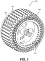
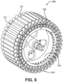
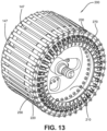
- FIGS. 1-22 show a system 200 in accordance with the present invention for curing and manufacturing partially cured pneumatic and/or non-pneumatic tire assemblies 140.
- the system 200 includes an annular hub member 210 slid into a corresponding annular, radially inner surface 142 of the tire assembly 140, a plurality of spacer members 220 for maintaining corresponding uniform cavity dimensions in the tire assembly 140 by fastening the spacer members 220 to the hub member 210 with flap members 147 of the tire assembly 140 enclosing a radially outermost surface 222 of each of the spacer members 220, first and second curing platens 230, 240 for axially securing the hub member 210 and spacer members 220 relative to each other, and a plurality of preferably triangular inserts 250 for creating a smooth, uniform outer cylindrical surface formed by a radially outer surface 252 of each triangular insert 250 and each of the flap members 147 of the tire assembly 140 positioned by the radially outermost surfaces 222 of the
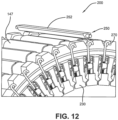
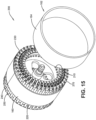
- An inner annular shear band 160 and an outer annular tread member 162 of the tire assembly 140 may be serially placed circumferentially around the uniform outer cylindrical surface 147, 252 and affixed at least temporarily thereto and to each other 160, 162. This may be accomplished by building up layers 160, 162 around the assembly 200 similar to a conventional tire building method (not shown) or by forming a complete annular band structure from the shear band 160 and the tread member 162 ( FIG. 15 ).
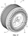
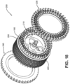
- a plurality of mold members 260 (six shown in FIG. 16 ) may be placed circumferentially around a radially outer surface 163 of the tread member 162.
- the mold members 260 have radially inner surfaces 262 for together forming a tread shaped outer surface in the outer surface 163 of the tread member 162.
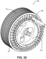
- the spacer members 220, curing platens 230, 240, triangular inserts 250, and mold members 260 may be heated in order to cure form the flap members 147, shear band 160, and tread member 162 (e.g., uncured parts of the tire assembly 140) into a molded integral part of a complete, cured tire assembly 170 having an appropriate tread 172 ( FIG. 21 ).
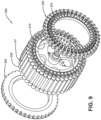
- the mold members 260 are radially removed from around the complete tire assembly 170, the curing platens 230, 240 are axially removed from the hub member 210, and the spacer members 220 and inserts 250 are axially withdrawn from the tire assembly 170 to reveal stable cavities 176 within a spoke structure 174 of the mount-ready tire assembly 170.
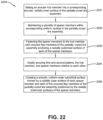
- a method 2200 cures and manufactures a partially cured tire assembly 140 into a completed, "ready-to-install", completely cured tire assembly 170.
- the method 2200 includes: a first step 2201 of sliding an annular hub member 210 into a corresponding annular, radially inner surface 142 of the partially-cured tire assembly 140; a second step 2202 of maintaining a plurality of spacer members 220 within corresponding uniform cavity dimensions in the partially-cured tire assembly 140; a third step 2203 of fastening the spacer members 220 to the hub member 210 with flap members 147 of the partially-cured tire assembly 140 enclosing a radially outermost surface 222 of each of the spacer members 220; a fourth step 220 of axially securing first and second curing platens 230, 240, the hub member 210, and spacer members 220 relative to each other; a fifth step 2205 of utilizing a plurality of triangular
- the method 2200 further includes a tenth step 2210 of heating (e.g., by a hot liquid, steam, electricity, etc.) the spacer members 220, curing platens 230, 240, triangular inserts 250, and mold members 260 in order to cure/form the flap members 147, shear band 160, and tread member 162 (e.g., uncured parts of the partially-cured tire assembly 140) into a molded integral part of a complete, cured tire assembly 170 having an appropriate tread 172; an eleventh step 2211 of radially removing the mold members 260 from around the complete, fully-cured tire assembly 170; a twelfth step 2212 of axially removing the curing platens 230, 240 from the hub member 210; and a thirteenth step 2213 of axially withdrawing the spacer members 220 and inserts 250 from the fully-cured tire assembly 170 to reveal stable cavities 176 within a spoke structure 174 of the rim-mountable, fully-cured tire assembly 1
Landscapes
- Engineering & Computer Science (AREA)
- Mechanical Engineering (AREA)
- Manufacturing & Machinery (AREA)
- Moulds For Moulding Plastics Or The Like (AREA)
- Tires In General (AREA)
- Heating, Cooling, Or Curing Plastics Or The Like In General (AREA)
- Tyre Moulding (AREA)
Claims (15)
- System zum Vulkanisieren und Herstellen einer teilweise vulkanisierten Reifenanordnung (140), wobei das System das Folgende umfasst:ein ringförmiges, als Nabe dienendes Element (210), das in eine entsprechende ringförmige, in der radialen Richtung innere Oberfläche (142) der teilweise vulkanisierten Reifenanordnung (140) eingeschoben wurde;eine Anzahl länglicher Abstandselemente (220), die dazu bestimmt sind, entsprechende gleichmäßige Hohlraumabmessungen in der teilweise vulkanisierten Reifenanordnung (140) durch eine Befestigung der Abstandselemente (220) an dem als Nabe dienenden Element (210) mit Laschenelementen (147) der teilweise vulkanisierten Reifenanordnung (140) aufrechtzuerhalten, um so eine radial äußerste Oberfläche (222) der Abstandselemente (220) zu umschließen;eine erste ringförmige Vulkanisierplatte (230) zum axialen Befestigen des als Nabe dienenden Elementes (210) und der Abstandselemente (220) relativ zu einander;eine zweite ringförmige Vulkanisierplatte (240) zum axialen Befestigen des als Nabe dienenden Elementes (210) und der Abstandselemente (220) relativ zu einander;eine Anzahl länglicher Einsätze (250), die dazu bestimmt sind, eine gleichmäßig glatte äußere zylindrische Oberfläche zu erzeugen, die durch eine in der radialen Richtung äußeren Oberfläche jedes Einsatzes (250) und von Laschenelementen (147) der teilweise vulkanisierten Reifenanordnung (140) ausgebildet wird, die über die radial äußersten Oberflächen (222) der Abstandselemente (220) positioniert ist.
- System wie in Anspruch 1 angegeben, das ferner eine Anzahl von Formelementen (260) umfasst, die in der Umfangsrichtung um eine in der radialen Richtung äußeren Oberfläche eines als Lauffläche dienenden Elements (162) angebracht sind.
- System wie in Anspruch 2 angegeben, wobei radial innere Oberflächen der Formelemente (260) gemeinsam eine äußere Oberfläche zum Erzielen einer Lauffläche in der radial äußeren Oberfläche des als Lauffläche dienenden Elements (162) bilden.
- System wie in mindestens einem der vorhergehenden Ansprüche angegeben, wobei die Abstandselemente (220), die erste und zweite Vulkanisierplatte (230, 244), die dreieckigen Einsätze (250) und die Formelemente (260) so angebracht sind, dass sie erwärmt werden können, um die Laschenelemente (147), das Scherband (160) und das als Lauffläche dienende Element (162) in ein einteiliges Element einer vollständigen vulkanisierten Reifenanordnung (170) heißzuformen.
- System wie in mindestens einem der vorhergehenden Ansprüche angegeben, wobei die länglichen Einsätze (250) im Querschnitt eine dreieckige Form besitzen.
- System wie in mindestens einem der vorhergehenden Ansprüche angegeben, wobei die Formelemente (260) von einer Stelle um die vollständige vulkanisierte Reifenanordnung (170) herum in der radialen Richtung beweglich sind; und/oder wobei die Vulkanisierplatten (230, 240) vom dem als Nabe dienenden Element (210), von den länglichen Abstandselementen (220) und von den länglichen Einsätzen (250) entfernt werden können.
- System wie in mindestens einem der vorhergehenden Ansprüche angegeben, wobei die Vulkanisierplatten (230, 240) so ausgebildet sind, dass sie durch eine heiße Flüssigkeit erwärmt werden können; und/oder wobei die länglichen Abstandelemente (220) so ausgebildet sind, dass sie mit Dampf erwärmt werden können; und/oder wobei die länglichen Einsätze (250) so ausgebildet sind, dass sie elektrisch erwärmt werden können.
- Verfahren zur Vervollständigung der Vulkanisation einer teilweise vulkanisierten Reifenanordnung (140), wobei das Verfahren die folgenden Schritte umfasst, bei denen:ein ringförmiges, als Nabe dienendes Element (210) in eine entsprechende ringförmige in der radialen Richtung innere Oberfläche (142) der teilweise vulkanisierten Reifenanordnung (140) eingeschoben wird;eine Anzahl von Abstandselementen (220) in entsprechenden gleichmäßigen Hohlräumen in der teilweise vulkanisierten Reifenanordnung (140) gehalten werden;die Abstandselemente (220) an dem als Nabe dienenden Element (210) mit unvulkanisierten Laschenelementen (147) der teilweise vulkanisierten Reifenanordnung (140) befestigt werden, um auf diese Weise eine in der radialen Richtung äußerste Oberfläche jedes der Abstandselemente (220) einzuschließen;erste und zweite Vulkanisierplatten (230, 240), das als Nabe dienende Element (210) und die Abstandselemente (220) axial relativ zueinander befestigt werden; undeine glatte, gleichmäßige äußere zylindrische Oberfläche durch eine in der radialen Richtung äußere Oberfläche jedes Abstandelementes (220) und jedes der unvulkanisierten Laschenelemente (147) der teilweise vulkanisierten Reifenanordnung (140) ausgebildet wird, die über die radial äußersten Oberflächen der Abstandselemente (220) positioniert ist.
- Verfahren wie in Anspruch 8 angegeben, das ferner einen Schritt umfasst, bei dem ein unvulkanisiertes ringförmiges inneres Scherband (160) und ein unvulkanisiertes ringförmiges äußeres Scherband (162) der teilweise vulkanisierten Reifenanordnung (140) in Umfangsrichtung um die äußere einheitliche zylindrische Oberfläche herum angebracht wird.
- Verfahren wie in Anspruch 9 angegeben, das ferner einen Schritt umfasst, bei dem das unvulkanisierte ringförmige innere Scherband (160) und das unvulkanisierte ringförmige äußere Scherband (162) der teilweise vulkanisierten Reifenanordnung (140) aneinander befestigt werden, und/oder das ferner einen Schritt umfasst, bei dem eine Anzahl von Formelementen (260) in der Umfangsrichtung um eine in der radialen Richtung äußere Oberfläche des als Lauffläche dienenden Elements (162) angebracht werden.
- Verfahren wie in Anspruch 10 angegeben, das ferner einen Schritt umfasst, bei dem in der Außenfläche des als Lauffläche dienenden Elements (162) eine Außenfläche gebildet wird, die eine Form einer Lauffläche besitzt, und zwar mittels in der radialen Richtung innen liegender Oberflächen der Formelemente (260).
- Verfahren wie in einem der vorhergehenden Ansprüche 8 bis 11 angegeben, das ferner einen Schritt umfasst, bei dem die Abstandselemente (220), die Vulkanisierplatten (230, 240), die länglichen Einsätze (250) und die Formteile (260) erwärmt werden, um die Laschenelemente (147), das Scherband (160) und das als Lauffläche dienende Element (162) in eine Reifenanordnung (170) umzuwandeln, die vollständig vulkanisiert ist.
- Verfahren wie in Anspruch 12 angegeben, das ferner einen Schritt umfasst, bei dem die Formelemente (260) von der Stelle um die vollständige vulkanisierte Reifenanordnung (170) entfernt werden; und/oder das ferner einen Schritt umfasst, bei dem die Vulkanisierplatten (230, 240) in der radialen Richtung von dem als Nabe dienenden Element (210) weg bewegt werden.
- Verfahren wie in Anspruch 12 oder 13 angegeben, das ferner einen Schritt umfasst, bei dem die Abstandselemente (220) und die Einsätze (250) aus der vollständig vulkanisierten Reifenanordnung (170) axial zurückgezogen werden, um stabile Hohlräume innerhalb einer Speichenstruktur (174) einer vollständig vulkanisierten Reifenanordnung (170) freizulegen, die an einer Felge angebracht werden kann.
- Verfahren wie in Anspruch 12 angegeben, wobei der Heizschritt die Verwendung eines Heizmittels umfasst, das aus der Gruppe ausgewählt ist, die eine heiße Flüssigkeit, Dampf und Elektrizität umfasst.
Applications Claiming Priority (1)
| Application Number | Priority Date | Filing Date | Title |
|---|---|---|---|
| US17/109,901 US20220168980A1 (en) | 2020-12-02 | 2020-12-02 | System for manufacturing a support structure |
Publications (3)
| Publication Number | Publication Date |
|---|---|
| EP4008539A2 EP4008539A2 (de) | 2022-06-08 |
| EP4008539A3 EP4008539A3 (de) | 2023-04-26 |
| EP4008539B1 true EP4008539B1 (de) | 2025-07-09 |
Family
ID=78676403
Family Applications (1)
| Application Number | Title | Priority Date | Filing Date |
|---|---|---|---|
| EP21208631.8A Active EP4008539B1 (de) | 2020-12-02 | 2021-11-16 | System und verfahren zur herstellung einer stützstruktur |
Country Status (6)
| Country | Link |
|---|---|
| US (1) | US20220168980A1 (de) |
| EP (1) | EP4008539B1 (de) |
| JP (1) | JP2022088331A (de) |
| KR (1) | KR102563673B1 (de) |
| CN (1) | CN114571765B (de) |
| BR (1) | BR102021023269A2 (de) |
Families Citing this family (2)
| Publication number | Priority date | Publication date | Assignee | Title |
|---|---|---|---|---|
| US11801651B2 (en) * | 2021-06-09 | 2023-10-31 | The Goodyear Tire & Rubber Company | System for manufacturing a support structure |
| EP4355567B1 (de) * | 2021-06-18 | 2026-02-04 | Bridgestone Americas Tire Operations, LLC | Härtungsformanordnungen für luftlose reifen sowie verfahren zur herstellung |
Family Cites Families (18)
| Publication number | Priority date | Publication date | Assignee | Title |
|---|---|---|---|---|
| US7878600B2 (en) * | 2007-06-05 | 2011-02-01 | Stellana U.S. Inc. | Mechanical fastener for polyurethane wheels |
| JP5084637B2 (ja) * | 2008-06-26 | 2012-11-28 | 東洋ゴム工業株式会社 | 非空気圧タイヤの成形型、および非空気圧タイヤの製造方法 |
| US9346499B2 (en) * | 2011-01-27 | 2016-05-24 | Irobot Corporation | Resilient wheel assemblies |
| CN104602900A (zh) * | 2012-09-07 | 2015-05-06 | 卡特彼勒公司 | 用于形成非充气轮胎的系统和方法 |
| US9149994B2 (en) * | 2012-12-12 | 2015-10-06 | Caterpillar Inc. | Systems for molding non-pneumatic tires |
| US20150034225A1 (en) * | 2013-07-30 | 2015-02-05 | Caterpillar Inc. | Reinforced non-pneumatic tire and system for molding reinforced non-pneumatic tire |
| US20150210025A1 (en) * | 2014-01-24 | 2015-07-30 | Caterpillar Inc. | System for molding non-pneumatic tires |
| WO2017072560A1 (en) * | 2015-10-30 | 2017-05-04 | Compagnie Generale Des Etablissements Michelin | Spoke fabrication for a non-pneumatic wheel |
| WO2017116472A1 (en) * | 2015-12-31 | 2017-07-06 | Compagnie Generale Des Etablissements Michelin | Non-pneumatic wheel and method of construction |
| WO2017116478A1 (en) * | 2015-12-31 | 2017-07-06 | Compagnie Generale Des Etablissements Michelin | Method and apparatus for wheel assembly |
| US10207544B2 (en) | 2016-11-15 | 2019-02-19 | The Goodyear Tire & Rubber Company | Wheel for a support structure |
| US10384409B2 (en) * | 2016-11-15 | 2019-08-20 | The Goodyear Tire & Rubber Company | Method of manufacturing a non-pneumatic support structure |
| EP3558696B1 (de) * | 2016-12-22 | 2022-03-02 | Compagnie Générale des Etablissements Michelin | Verfahren zur montage eines luftlosen reifens auf einer nabe |
| EP3615351B1 (de) * | 2017-04-27 | 2023-03-29 | Bridgestone Americas Tire Operations, LLC | Reifen mit speichenschlaufen |
| US10471773B2 (en) * | 2017-06-07 | 2019-11-12 | The Goodyear Tire & Rubber Company | Method of manufacturing a non-pneumatic support structure |
| US10603956B2 (en) * | 2018-03-28 | 2020-03-31 | The Goodyear Tire & Rubber Company | Wheel for a support structure |
| US11110749B2 (en) * | 2018-07-24 | 2021-09-07 | The Goodyear Tire & Rubber Company | Wheel for a support structure |
| CN109291737B (zh) * | 2018-10-29 | 2020-11-27 | 五河县纬立农业科技有限公司 | 用于工矿重载车辆的实心轮胎及其制造方法 |
-
2020
- 2020-12-02 US US17/109,901 patent/US20220168980A1/en not_active Abandoned
-
2021
- 2021-11-16 EP EP21208631.8A patent/EP4008539B1/de active Active
- 2021-11-19 BR BR102021023269-2A patent/BR102021023269A2/pt not_active Application Discontinuation
- 2021-11-25 KR KR1020210163961A patent/KR102563673B1/ko active Active
- 2021-11-26 JP JP2021191706A patent/JP2022088331A/ja active Pending
- 2021-12-02 CN CN202111461893.6A patent/CN114571765B/zh active Active
Also Published As
| Publication number | Publication date |
|---|---|
| EP4008539A3 (de) | 2023-04-26 |
| CN114571765B (zh) | 2025-01-28 |
| BR102021023269A2 (pt) | 2022-08-09 |
| KR20220077876A (ko) | 2022-06-09 |
| CN114571765A (zh) | 2022-06-03 |
| US20220168980A1 (en) | 2022-06-02 |
| EP4008539A2 (de) | 2022-06-08 |
| KR102563673B1 (ko) | 2023-08-03 |
| JP2022088331A (ja) | 2022-06-14 |
Similar Documents
| Publication | Publication Date | Title |
|---|---|---|
| US11020918B2 (en) | Method of manufacturing a non-pneumatic support structure | |
| US10040317B2 (en) | Non-pneumatic support structure | |
| US10207544B2 (en) | Wheel for a support structure | |
| US10603956B2 (en) | Wheel for a support structure | |
| US11001021B2 (en) | Method of manufacturing a non-pneumatic support structure | |
| EP3599107B1 (de) | Rad für eine stützstruktur | |
| EP4008539B1 (de) | System und verfahren zur herstellung einer stützstruktur | |
| EP4008563B1 (de) | Reifen-/radanordnung und verfahren zum tragen eines fahrzeugs | |
| JP7526075B2 (ja) | 支持構造物のためのホイール | |
| EP4112286A1 (de) | System und verfahren zur herstellung einer stützstruktur | |
| EP4008540B1 (de) | System und verfahren zur herstellung einer stützstruktur | |
| US12202219B2 (en) | System for manufacturing a support structure | |
| EP4197807B1 (de) | Reifen-/felgenanordnung für eine stützstruktur |
Legal Events
| Date | Code | Title | Description |
|---|---|---|---|
| PUAI | Public reference made under article 153(3) epc to a published international application that has entered the european phase |
Free format text: ORIGINAL CODE: 0009012 |
|
| STAA | Information on the status of an ep patent application or granted ep patent |
Free format text: STATUS: THE APPLICATION HAS BEEN PUBLISHED |
|
| AK | Designated contracting states |
Kind code of ref document: A2 Designated state(s): AL AT BE BG CH CY CZ DE DK EE ES FI FR GB GR HR HU IE IS IT LI LT LU LV MC MK MT NL NO PL PT RO RS SE SI SK SM TR |
|
| RAP3 | Party data changed (applicant data changed or rights of an application transferred) |
Owner name: THE GOODYEAR TIRE & RUBBER COMPANY |
|
| PUAL | Search report despatched |
Free format text: ORIGINAL CODE: 0009013 |
|
| AK | Designated contracting states |
Kind code of ref document: A3 Designated state(s): AL AT BE BG CH CY CZ DE DK EE ES FI FR GB GR HR HU IE IS IT LI LT LU LV MC MK MT NL NO PL PT RO RS SE SI SK SM TR |
|
| RIC1 | Information provided on ipc code assigned before grant |
Ipc: B60C 7/14 20060101ALI20230320BHEP Ipc: B29C 33/30 20060101ALI20230320BHEP Ipc: B29D 30/02 20060101AFI20230320BHEP |
|
| STAA | Information on the status of an ep patent application or granted ep patent |
Free format text: STATUS: REQUEST FOR EXAMINATION WAS MADE |
|
| 17P | Request for examination filed |
Effective date: 20231026 |
|
| RBV | Designated contracting states (corrected) |
Designated state(s): AL AT BE BG CH CY CZ DE DK EE ES FI FR GB GR HR HU IE IS IT LI LT LU LV MC MK MT NL NO PL PT RO RS SE SI SK SM TR |
|
| GRAP | Despatch of communication of intention to grant a patent |
Free format text: ORIGINAL CODE: EPIDOSNIGR1 |
|
| STAA | Information on the status of an ep patent application or granted ep patent |
Free format text: STATUS: GRANT OF PATENT IS INTENDED |
|
| INTG | Intention to grant announced |
Effective date: 20250207 |
|
| GRAS | Grant fee paid |
Free format text: ORIGINAL CODE: EPIDOSNIGR3 |
|
| GRAA | (expected) grant |
Free format text: ORIGINAL CODE: 0009210 |
|
| STAA | Information on the status of an ep patent application or granted ep patent |
Free format text: STATUS: THE PATENT HAS BEEN GRANTED |
|
| AK | Designated contracting states |
Kind code of ref document: B1 Designated state(s): AL AT BE BG CH CY CZ DE DK EE ES FI FR GB GR HR HU IE IS IT LI LT LU LV MC MK MT NL NO PL PT RO RS SE SI SK SM TR |
|
| REG | Reference to a national code |
Ref country code: GB Ref legal event code: FG4D |
|
| REG | Reference to a national code |
Ref country code: CH Ref legal event code: EP |
|
| REG | Reference to a national code |
Ref country code: IE Ref legal event code: FG4D |
|
| REG | Reference to a national code |
Ref country code: DE Ref legal event code: R096 Ref document number: 602021033709 Country of ref document: DE |
|
| REG | Reference to a national code |
Ref country code: NL Ref legal event code: MP Effective date: 20250709 |
|
| PG25 | Lapsed in a contracting state [announced via postgrant information from national office to epo] |
Ref country code: PT Free format text: LAPSE BECAUSE OF FAILURE TO SUBMIT A TRANSLATION OF THE DESCRIPTION OR TO PAY THE FEE WITHIN THE PRESCRIBED TIME-LIMIT Effective date: 20251110 |
|
| PG25 | Lapsed in a contracting state [announced via postgrant information from national office to epo] |
Ref country code: NL Free format text: LAPSE BECAUSE OF FAILURE TO SUBMIT A TRANSLATION OF THE DESCRIPTION OR TO PAY THE FEE WITHIN THE PRESCRIBED TIME-LIMIT Effective date: 20250709 |
|
| REG | Reference to a national code |
Ref country code: AT Ref legal event code: MK05 Ref document number: 1811502 Country of ref document: AT Kind code of ref document: T Effective date: 20250709 |
|
| PG25 | Lapsed in a contracting state [announced via postgrant information from national office to epo] |
Ref country code: IS Free format text: LAPSE BECAUSE OF FAILURE TO SUBMIT A TRANSLATION OF THE DESCRIPTION OR TO PAY THE FEE WITHIN THE PRESCRIBED TIME-LIMIT Effective date: 20251109 |
|
| PGFP | Annual fee paid to national office [announced via postgrant information from national office to epo] |
Ref country code: DE Payment date: 20251126 Year of fee payment: 5 |
|
| PGFP | Annual fee paid to national office [announced via postgrant information from national office to epo] |
Ref country code: GB Payment date: 20251121 Year of fee payment: 5 |
|
| PG25 | Lapsed in a contracting state [announced via postgrant information from national office to epo] |
Ref country code: NO Free format text: LAPSE BECAUSE OF FAILURE TO SUBMIT A TRANSLATION OF THE DESCRIPTION OR TO PAY THE FEE WITHIN THE PRESCRIBED TIME-LIMIT Effective date: 20251009 |
|
| REG | Reference to a national code |
Ref country code: LT Ref legal event code: MG9D |
|
| PG25 | Lapsed in a contracting state [announced via postgrant information from national office to epo] |
Ref country code: AT Free format text: LAPSE BECAUSE OF FAILURE TO SUBMIT A TRANSLATION OF THE DESCRIPTION OR TO PAY THE FEE WITHIN THE PRESCRIBED TIME-LIMIT Effective date: 20250709 |
|
| PG25 | Lapsed in a contracting state [announced via postgrant information from national office to epo] |
Ref country code: FI Free format text: LAPSE BECAUSE OF FAILURE TO SUBMIT A TRANSLATION OF THE DESCRIPTION OR TO PAY THE FEE WITHIN THE PRESCRIBED TIME-LIMIT Effective date: 20250709 |
|
| PG25 | Lapsed in a contracting state [announced via postgrant information from national office to epo] |
Ref country code: HR Free format text: LAPSE BECAUSE OF FAILURE TO SUBMIT A TRANSLATION OF THE DESCRIPTION OR TO PAY THE FEE WITHIN THE PRESCRIBED TIME-LIMIT Effective date: 20250709 |
|
| PGFP | Annual fee paid to national office [announced via postgrant information from national office to epo] |
Ref country code: FR Payment date: 20251120 Year of fee payment: 5 |
|
| PG25 | Lapsed in a contracting state [announced via postgrant information from national office to epo] |
Ref country code: GR Free format text: LAPSE BECAUSE OF FAILURE TO SUBMIT A TRANSLATION OF THE DESCRIPTION OR TO PAY THE FEE WITHIN THE PRESCRIBED TIME-LIMIT Effective date: 20251010 |
|
| PG25 | Lapsed in a contracting state [announced via postgrant information from national office to epo] |
Ref country code: SE Free format text: LAPSE BECAUSE OF FAILURE TO SUBMIT A TRANSLATION OF THE DESCRIPTION OR TO PAY THE FEE WITHIN THE PRESCRIBED TIME-LIMIT Effective date: 20250709 |
|
| PG25 | Lapsed in a contracting state [announced via postgrant information from national office to epo] |
Ref country code: LV Free format text: LAPSE BECAUSE OF FAILURE TO SUBMIT A TRANSLATION OF THE DESCRIPTION OR TO PAY THE FEE WITHIN THE PRESCRIBED TIME-LIMIT Effective date: 20250709 |
|
| PG25 | Lapsed in a contracting state [announced via postgrant information from national office to epo] |
Ref country code: BG Free format text: LAPSE BECAUSE OF FAILURE TO SUBMIT A TRANSLATION OF THE DESCRIPTION OR TO PAY THE FEE WITHIN THE PRESCRIBED TIME-LIMIT Effective date: 20250709 Ref country code: PL Free format text: LAPSE BECAUSE OF FAILURE TO SUBMIT A TRANSLATION OF THE DESCRIPTION OR TO PAY THE FEE WITHIN THE PRESCRIBED TIME-LIMIT Effective date: 20250709 |
|
| PG25 | Lapsed in a contracting state [announced via postgrant information from national office to epo] |
Ref country code: RS Free format text: LAPSE BECAUSE OF FAILURE TO SUBMIT A TRANSLATION OF THE DESCRIPTION OR TO PAY THE FEE WITHIN THE PRESCRIBED TIME-LIMIT Effective date: 20251009 |
|
| PG25 | Lapsed in a contracting state [announced via postgrant information from national office to epo] |
Ref country code: ES Free format text: LAPSE BECAUSE OF FAILURE TO SUBMIT A TRANSLATION OF THE DESCRIPTION OR TO PAY THE FEE WITHIN THE PRESCRIBED TIME-LIMIT Effective date: 20250709 |
|
| PG25 | Lapsed in a contracting state [announced via postgrant information from national office to epo] |
Ref country code: RO Free format text: LAPSE BECAUSE OF FAILURE TO SUBMIT A TRANSLATION OF THE DESCRIPTION OR TO PAY THE FEE WITHIN THE PRESCRIBED TIME-LIMIT Effective date: 20250709 |
|
| PG25 | Lapsed in a contracting state [announced via postgrant information from national office to epo] |
Ref country code: SM Free format text: LAPSE BECAUSE OF FAILURE TO SUBMIT A TRANSLATION OF THE DESCRIPTION OR TO PAY THE FEE WITHIN THE PRESCRIBED TIME-LIMIT Effective date: 20250709 |
|
| PG25 | Lapsed in a contracting state [announced via postgrant information from national office to epo] |
Ref country code: DK Free format text: LAPSE BECAUSE OF FAILURE TO SUBMIT A TRANSLATION OF THE DESCRIPTION OR TO PAY THE FEE WITHIN THE PRESCRIBED TIME-LIMIT Effective date: 20250709 |
|
| PG25 | Lapsed in a contracting state [announced via postgrant information from national office to epo] |
Ref country code: IT Free format text: LAPSE BECAUSE OF FAILURE TO SUBMIT A TRANSLATION OF THE DESCRIPTION OR TO PAY THE FEE WITHIN THE PRESCRIBED TIME-LIMIT Effective date: 20250709 |