EP4197807B1 - Reifen-/felgenanordnung für eine stützstruktur - Google Patents
Reifen-/felgenanordnung für eine stützstruktur Download PDFInfo
- Publication number
- EP4197807B1 EP4197807B1 EP22212399.4A EP22212399A EP4197807B1 EP 4197807 B1 EP4197807 B1 EP 4197807B1 EP 22212399 A EP22212399 A EP 22212399A EP 4197807 B1 EP4197807 B1 EP 4197807B1
- Authority
- EP
- European Patent Office
- Prior art keywords
- tire
- rim
- ring flange
- shafts
- circular
- Prior art date
- Legal status (The legal status is an assumption and is not a legal conclusion. Google has not performed a legal analysis and makes no representation as to the accuracy of the status listed.)
- Active
Links
Images


Classifications
-
- B—PERFORMING OPERATIONS; TRANSPORTING
- B60—VEHICLES IN GENERAL
- B60C—VEHICLE TYRES; TYRE INFLATION; TYRE CHANGING; CONNECTING VALVES TO INFLATABLE ELASTIC BODIES IN GENERAL; DEVICES OR ARRANGEMENTS RELATED TO TYRES
- B60C7/00—Non-inflatable or solid tyres
- B60C7/24—Non-inflatable or solid tyres characterised by means for securing tyres on rim or wheel body
- B60C7/26—Non-inflatable or solid tyres characterised by means for securing tyres on rim or wheel body using bolts
-
- B—PERFORMING OPERATIONS; TRANSPORTING
- B60—VEHICLES IN GENERAL
- B60B—VEHICLE WHEELS; CASTORS; AXLES FOR WHEELS OR CASTORS; INCREASING WHEEL ADHESION
- B60B1/00—Spoked wheels; Spokes thereof
- B60B1/06—Wheels with compression spokes
-
- B—PERFORMING OPERATIONS; TRANSPORTING
- B60—VEHICLES IN GENERAL
- B60B—VEHICLE WHEELS; CASTORS; AXLES FOR WHEELS OR CASTORS; INCREASING WHEEL ADHESION
- B60B1/00—Spoked wheels; Spokes thereof
- B60B1/06—Wheels with compression spokes
- B60B1/14—Attaching spokes to rim or hub
-
- B—PERFORMING OPERATIONS; TRANSPORTING
- B60—VEHICLES IN GENERAL
- B60C—VEHICLE TYRES; TYRE INFLATION; TYRE CHANGING; CONNECTING VALVES TO INFLATABLE ELASTIC BODIES IN GENERAL; DEVICES OR ARRANGEMENTS RELATED TO TYRES
- B60C7/00—Non-inflatable or solid tyres
- B60C7/10—Non-inflatable or solid tyres characterised by means for increasing resiliency
- B60C7/107—Non-inflatable or solid tyres characterised by means for increasing resiliency comprising lateral openings
-
- B—PERFORMING OPERATIONS; TRANSPORTING
- B60—VEHICLES IN GENERAL
- B60C—VEHICLE TYRES; TYRE INFLATION; TYRE CHANGING; CONNECTING VALVES TO INFLATABLE ELASTIC BODIES IN GENERAL; DEVICES OR ARRANGEMENTS RELATED TO TYRES
- B60C7/00—Non-inflatable or solid tyres
- B60C7/10—Non-inflatable or solid tyres characterised by means for increasing resiliency
- B60C7/14—Non-inflatable or solid tyres characterised by means for increasing resiliency using springs
- B60C7/146—Non-inflatable or solid tyres characterised by means for increasing resiliency using springs extending substantially radially, e.g. like spokes
-
- B—PERFORMING OPERATIONS; TRANSPORTING
- B60—VEHICLES IN GENERAL
- B60B—VEHICLE WHEELS; CASTORS; AXLES FOR WHEELS OR CASTORS; INCREASING WHEEL ADHESION
- B60B9/00—Wheels of high resiliency, e.g. with conical interacting pressure-surfaces
Definitions
- the present invention relates to tire/rim assemblies, and more particularly, to non-pneumatic tire assemblies.
- Radial pneumatic tires rely on the ply reinforcement to carry and transfer the load between the rim and the belt layer. These ply cords need to be tensioned to carry the load. Tensioning of these ply cords is achieved with the pressurized air in the inner chamber of the tire. If air pressure is lost, load carrying capacity of a pneumatic tire decreases significantly. Preventing the slow or sudden air pressure loss has been a challenge for the tire makers.
- One proposed solution is to use non-pneumatic tires.
- a top loader non-pneumatic tire can perform similar to a pneumatic tire if its durability, speed rating/limit and load capacity can be increased to the levels of a pneumatic tire.
- top loader non-pneumatic tires rely on the polymeric spokes to carry the load of the vehicle. Spokes transfer the load from the rim to the shear band. Due to the characteristics of the polymeric materials used in the spokes of these tires, performance of these tires is limited. It is an object of the present invention to overcome this limitation and increase the load carrying capacity and durability of these spokes and hence the performance of the top loader non-pneumatic tire.
- the invention relates to a tire and rim assembly in accordance with claim 1.
- a tire and rim assembly includes a tire, a circular hub member for securing to a rotatable axle of a vehicle, a rim piece for engaging the hub member, the rim piece having a first annular ring flange for engaging the tire, a second annular ring flange for engaging the tire, and a plurality of cylindrical shafts for each axially engaging the first annular ring flange at one axial end of each of the shafts and the second annular ring flange at another opposite axial end of each of the shafts.
- the first ring flange has first circular openings arrayed circumferentially about the first ring piece.
- the second ring flange has second circular openings arrayed circumferentially about the second ring flange.
- each of the first circular openings of the rim piece is axially aligned with a corresponding first bore hole of one of the shafts.
- each shaft engages a corresponding loop of the tire.
- Each shaft engages a cylindrical inner radial surface of a corresponding loop of the tire.
- the rim piece and ring flanges are constructed of a metal.
- the rim piece and ring flanges are constructed of a polymer.
- a method for non-pneumatically supporting a vehicle load includes the steps of: axially engaging first axial ends of a plurality of the shafts with a first bolt member; axially and radially engaging loop members of a tire with corresponding radially outer surfaces of each of the shafts; axially engaging second opposite ends of the shafts with a second bolt member; threadedly securing the first bolt members secured through a corresponding first bore hole of one of the shafts; threadedly securing the second bolt members through a corresponding opposite second bore hole of one of the shafts; securing a circular hub member to the rim piece; and rotationally attaching the circular hub member to a vehicle.
- a further step includes arraying first circular openings circumferentially about the first ring flange.
- a further step includes arraying second circular openings circumferentially about the second ring flange.
- a further step includes engaging radial outer surface of loops of a tire with the shafts.
- a conventional rim/tire assembly may have an outer ring, such as a shear band, flexibly connected to a central hub by means of lightweight composite springs.
- the springs may be plates fixed to the ring and to the hub.
- the hub may contain a speed reduction gear unit and/or an electric motor and may have a suspension mechanism for connecting a vehicle chassis to each wheel.
- the ring may be constructed from a flexible composite material, such as carbon fiber reinforced nylon material and have twin rubber tires and a plurality of circumferentially spaced-apart radial cleats which engage the ground and provide improved traction.
- the hub may also be formed from a carbon fiber reinforced composite material.
- Another conventional wheel may have a rubber strip with a molded tread bonded to a composite ring for improved grip.
- the springs interconnecting the ring and hub may be S-shaped lightweight composite springs.
- Another conventional rim/tire assembly may be formed from a lightweight composite material, such as carbon fiber reinforced polyamide.
- the assembly may have a cylindrical central hub and a circular outer flexible rim mounted on the central hub by an endless looped spring band extending between the central hub and the circular rim. Six radial loops may be defined by the spring band.
- the spring band may be attached to the central hub and to the circular rim by any suitable means, such as adhesion, cohesion, soldering and/or mechanical fixing by means of bolts, rivets, and/or clamps.
- An example rim/tire assembly such as that described in US-B-10,207,544 and US-B-10,603,956 , may be formed from a lightweight polymer material, such as, for example, a standard tire rubber compound, a thermoplastic polymer, polyethylene terephthalate (PET), polyether ether ketone (PEEK), a cross-linking polymer like natural rubber, synthetic rubber-like polymers, epoxy resins, and/or phenolic resins.
- the assembly may have an inner central rim, such as an automobile wheel (not shown), and a circular outer flexible ring, which may include a shear band and tread structure, mounted on the inner central rim by a continuous cord/fabric reinforced spoke structure extending between the inner central rim and the outer ring.
- the spoke structure may define a plurality of cavities disposed concentrically about the inner central rim allowing the spoke structure to deflect under load thereby defining a suitable balance between flexibility for ride comfort and traction within a footprint of the assembly and stiffness for vehicle handling, low rolling resistance, and low heat build-up within the spoke structure.
- the cavities of the spoke structure may further define openings for arms of the inner central rim to extend therethrough and secure the spoke structure to the inner central rim.
- the arms may engage portions in a mechanical interlocking arrangement.
- the inner central rim may further include plates that, along with the arms may sandwich the portions of the spoke structure and create a further frictional and/or adhesive securement between the inner central rim and the spoke structure.
- the spoke structure may comprise a homogenous or heterogeneous polymer and/or a filled polymer.
- the spokes may include one or more reinforcing layers.
- the layer(s) may be constructed of single end dipped cords, conventional pneumatic tire ply/cord arrangements, short fibers, and/or polymeric film. Further, these constructions may be PET, nylon 6, nylon 6,6, rayon, steel, glass fibers, carbon fiber, aramid, and/or a hybrid construction of these materials.
- the cords may be from 400 denier to 9000 denier.
- the polymeric film may be from 0.1 mm to 2.0 mm thick.
- the spokes may be oriented at angle between 0 degrees and 90 degrees.
- the reinforcement of the spokes may be continuously reinforced across their entire axial length. Continuous reinforcement layer(s) may extend radially outward to multiple locations adjacent to a shear band at the outer flexible ring.
- Each cavity may have a common cross-sectional profile about the axis of rotation of the assembly. Further, each cavity may have a common axial length equal to a uniform axial thickness of the spoke structure. Each cavity may be curvedly shaped to prevent "pinch" points on the reinforcement layer(s) and mitigate compressive stress concentrations on the reinforcement layer(s). The number of cavities may be between 2 and 60 for large scale tire assemblies.
- the inner central rim may include steel, cast iron, aluminum, aluminum alloys, magnesium allows, and/or iron alloys.
- FIGS. 1 through 8 show a tire/rim assembly 200 in accordance with the present invention for use with pneumatic and/or non-pneumatic tire assemblies, such as the example tire assembly described above.
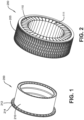
- the tire/rim assembly 200 includes an annular cylindrical rim piece 210 secured to a hub member 207 and rotatable axle or similar structure of a vehicle (not shown).
- the rim piece 210 may be constructed of any suitable material, such as metal, polymer, ceramic, and/or a combination thereof.
- the rim piece 210 has a first annular ring flange 212 extending circumferentially about one end of the rim piece 210.
- the first ring flange 212 further has first circular openings 214 arrayed circumferentially about the ring flange 212.
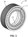
- the tire/rim assembly 200 further includes a plurality of annular shafts 220 each engaging a corresponding first circular opening 214 of the first ring flange 212.
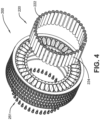
- Each shaft 220 further includes two threaded central bore holes 222 extending axially inward from each axial end of each shaft 220. Radially outer surfaces 224 of each of the shafts 220 engage corresponding loops 111 of a spoke structure 110 of an example tire assembly 205.
- each first circular opening 214 of the first ring flange 212 aligns axially with a corresponding first bore hole 222 of the first ring flange 212 ( FIG. 4 ).
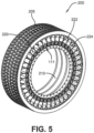
- Each corresponding pair of first circular openings/first bore holes 214, 222 is radially, axially, and circumferentially secured and fixed in these aligned relative positions by a corresponding first bolt member of a plurality of first bolt members 251 thereby sandwiching the loops 111 of the tire 205 between the rim piece 210 and each of the outer surfaces 224 of the shafts 220 ( FIG. 5 ).
- a second annular ring flange 230 axially secures the sandwiched loops 111 of the tire 205 to the assembled elements 205, 210, 220 by securing a second bolt member of a plurality of second bolt members 252 through a corresponding second circular opening 234 of a second ring flange 230 to a corresponding opposite threaded bore hole 222 of one of the shafts 220 ( FIG. 6 ).
- each corresponding pair of second circular openings/second bore holes 234, 222 is radially, axially, and circumferentially secured and fixed in these aligned relative positions ( FIG. 7 ).
- the hub member 207 are then secured to the tire/rim assembly 200 ( FIG. 8 ) enabling attachment of the tire assembly 200 to a vehicle (not shown).
- a method for non-pneumatically supporting a vehicle load includes: a first step such that first axial ends of each of the cylindrical shafts 220 axially engage each of the first bolt members 251; a second step such that loop members 111 of the example tire assembly 205 each axially and radially engage corresponding radially outer surfaces 224 of each of the shafts 220; a third step such that second opposite ends of each of the cylindrical shafts 220 axially engage a corresponding second bolt member 252; a fourth step such that the first bolt members 151 are each threadedly secured through a corresponding bore hole 222 of one of the shafts 220; a fifth step such that the second 252 are each threadedly secured through a corresponding opposite bore hole 222 of one of the shafts 220; and a sixth step such that a circular hub member 207 is secured (e.g., welded, bolted, interference fit, etc.) to the rim piece 210 allowing rotational attachment to a vehicle (not shown).
Landscapes
- Engineering & Computer Science (AREA)
- Mechanical Engineering (AREA)
- Tires In General (AREA)
Claims (5)
- Anordnung eines Luftreifens und einer Felge, die das Folgende umfasst:einen Luftreifen (205) ;ein kreisförmiges Element (207), das als Nabe dient, die zur Befestigung einer Drehachse eines Fahrzeugs bestimmt ist ;ein Teil (210) in der Form einer Felge, das dazu bestimmt ist, mit dem Nabenelement (207) in Kontakt zu treten, wobei das Teil (210) in der Form einer Felge ein erstes ringförmiges Felgenhorn (212) besitzt, das dazu bestimmt ist, mit dem Luftreifen (205) in Kontakt zu treten;ein zweites ringförmiges Felgenhorn (230), das dazu bestimmt ist, mit dem Luftreifen (205) in Kontakt zu treten; undeine Anzahl von zylindrischen Wellen (220), die jeweils dazu bestimmt sind, in der axialen Richtung mit dem ersten ringförmigen Felgenhorn (212) an einem axialen Ende jeder der Wellen (220) und mit dem zweiten ringförmigen Felgenhorn (230) an einem anderen, gegenüberliegenden axialen Ende jeder der Wellen (220) in Kontakt zu treten ; wobei das erste ringförmige Felgenhorn (212) kreisförmige Öffnungen (214) besitzt, die in der Umfangsrichtung um das erste ringförmige Felgenhorn (212) herum ausgebreitet sind ; und wobei die mehreren zylindrischen Wellen (220) jeweils mit einer entsprechenden ersten kreisförmigen Öffnung (214) des ersten ringförmigen Felgenhorns (212) in kontakt treten; wobei jede Welle (220) ferner zwei zentrale Löcher (222) in der Form von Bohrungen umfasst, die sich in der axialen Richtung innerhalb jedes axialen Endes jeder Welle (220) erstrecken ;dadurch gekennzeichnet, dass die zwei zentralen Löcher (222) in der Form von Bohrungen zwei zentrale Löcher (222) in der Form von Gewindebohrungen darstellen; dass die mehreren zylindrischen Wellen einen Querschnitt in kreisförmiger Form besitzen ; dass ihre Außenflächen in der radialen Richtung (224) mit einer jeweiligen zylindrischen radialen Innenfläche einer entsprechenden Schlaufe (111) des Reifens (205) in Kontakt treten; und dass das zweite ringförmige Felgenhorn (230) an dem Luftreifen (205) und dem Teil (210) in der Form einer Felge an dem Luftreifen angebracht und von diesem wieder entfernt werden kann.
- Anordnung aus einem Luftreifen und einer Felge, wie in Anspruch 1 dargestellt, wobei das zweite ringförmige Felgenhorn (230) zweite kreisförmige Öffnungen besitzt, die in Umfangsrichtung um das zweite ringförmige Felgenhorn (230) herum ausgebreitet sind.
- Anordnung aus einem Luftreifen und einer Felge, wie in Anspruch 1 oder 2 dargestellt, wobei jede der ersten kreisförmigen Öffnungen (214) in der axialen Richtung in Ausrichtung mit einem ersten Loch (222) in der Form einer Bohrung einer der Wellen (220) angebracht ist.
- Anordnung eines Luftreifens und einer Felge, wie in mindestens einem der vorhergehenden Ansprüche dargestellt, wobei das Teil (210) in der Form einer Felge sowie die ringförmigen Felgenhörner (212, 230) aus einem Metall gebildet sind.
- Anordnung aus einem Luftreifen und einer Felge, wie in mindestens einem der vorhergehenden Ansprüche dargestellt, wobei das Teil (210) in der Form einer Felge sowie die ringförmigen Felgenhörner (212, 230) aus einem Polymer gebildet sind.
Applications Claiming Priority (1)
| Application Number | Priority Date | Filing Date | Title |
|---|---|---|---|
| US17/552,417 US11975574B2 (en) | 2021-12-16 | 2021-12-16 | Tire/wheel assembly for a support structure |
Publications (2)
| Publication Number | Publication Date |
|---|---|
| EP4197807A1 EP4197807A1 (de) | 2023-06-21 |
| EP4197807B1 true EP4197807B1 (de) | 2025-05-14 |
Family
ID=84487525
Family Applications (1)
| Application Number | Title | Priority Date | Filing Date |
|---|---|---|---|
| EP22212399.4A Active EP4197807B1 (de) | 2021-12-16 | 2022-12-09 | Reifen-/felgenanordnung für eine stützstruktur |
Country Status (2)
| Country | Link |
|---|---|
| US (1) | US11975574B2 (de) |
| EP (1) | EP4197807B1 (de) |
Family Cites Families (12)
| Publication number | Priority date | Publication date | Assignee | Title |
|---|---|---|---|---|
| WO2011025491A1 (en) * | 2009-08-28 | 2011-03-03 | Michelin Recherche Et Technique, S.A. | A non-pneumatic wheel assembly with removable hub |
| US10207544B2 (en) | 2016-11-15 | 2019-02-19 | The Goodyear Tire & Rubber Company | Wheel for a support structure |
| US10286725B2 (en) | 2017-03-22 | 2019-05-14 | The Goodyear Tire & Rubber Company | Non-pneumatic support structure |
| KR102005417B1 (ko) * | 2017-09-11 | 2019-07-30 | 금호타이어 주식회사 | 비공기입 타이어용 림 및 이를 포함하는 휠 |
| WO2019054523A1 (ko) * | 2017-09-12 | 2019-03-21 | 이성기 | 비 공기식 차륜 |
| US10406852B2 (en) | 2017-10-27 | 2019-09-10 | The Goodyear Tire & Rubber Company | Non-pneumatic support structure |
| US10457094B2 (en) | 2017-12-11 | 2019-10-29 | The Goodyear Tire & Rubber Company | Wheel for a support structure |
| US10603956B2 (en) * | 2018-03-28 | 2020-03-31 | The Goodyear Tire & Rubber Company | Wheel for a support structure |
| US11110749B2 (en) | 2018-07-24 | 2021-09-07 | The Goodyear Tire & Rubber Company | Wheel for a support structure |
| CN112469575B (zh) | 2018-07-27 | 2022-12-02 | 普利司通美国轮胎运营有限责任公司 | 用于非充气轮胎的可重复使用的轮辋 |
| US11827062B2 (en) | 2019-08-29 | 2023-11-28 | The Goodyear Tire & Rubber Company | Non-pneumatic tire with a flexible looped spoke and method of forming |
| US11697307B2 (en) | 2020-12-04 | 2023-07-11 | The Goodyear Tire & Rubber Company | Wheel for a support structure |
-
2021
- 2021-12-16 US US17/552,417 patent/US11975574B2/en active Active
-
2022
- 2022-12-09 EP EP22212399.4A patent/EP4197807B1/de active Active
Also Published As
| Publication number | Publication date |
|---|---|
| EP4197807A1 (de) | 2023-06-21 |
| US20230191838A1 (en) | 2023-06-22 |
| US11975574B2 (en) | 2024-05-07 |
Similar Documents
| Publication | Publication Date | Title |
|---|---|---|
| US10821774B2 (en) | Non-pneumatic support structure | |
| US10207544B2 (en) | Wheel for a support structure | |
| US10040317B2 (en) | Non-pneumatic support structure | |
| US10603956B2 (en) | Wheel for a support structure | |
| US10864772B2 (en) | Wheel for a support structure | |
| EP3599107B1 (de) | Rad für eine stützstruktur | |
| EP4008539B1 (de) | System und verfahren zur herstellung einer stützstruktur | |
| EP4008563B1 (de) | Reifen-/radanordnung und verfahren zum tragen eines fahrzeugs | |
| EP4197807B1 (de) | Reifen-/felgenanordnung für eine stützstruktur | |
| EP3822092B1 (de) | Radanordnung für eine stützstruktur | |
| EP3812168B1 (de) | Modulare nicht-pneumatische stützstruktur und verfahren | |
| US11794513B2 (en) | Wheel for a support structure | |
| US11801651B2 (en) | System for manufacturing a support structure | |
| US12202219B2 (en) | System for manufacturing a support structure | |
| US11806960B2 (en) | System for manufacturing a support structure |
Legal Events
| Date | Code | Title | Description |
|---|---|---|---|
| PUAI | Public reference made under article 153(3) epc to a published international application that has entered the european phase |
Free format text: ORIGINAL CODE: 0009012 |
|
| STAA | Information on the status of an ep patent application or granted ep patent |
Free format text: STATUS: THE APPLICATION HAS BEEN PUBLISHED |
|
| AK | Designated contracting states |
Kind code of ref document: A1 Designated state(s): AL AT BE BG CH CY CZ DE DK EE ES FI FR GB GR HR HU IE IS IT LI LT LU LV MC ME MK MT NL NO PL PT RO RS SE SI SK SM TR |
|
| STAA | Information on the status of an ep patent application or granted ep patent |
Free format text: STATUS: REQUEST FOR EXAMINATION WAS MADE |
|
| 17P | Request for examination filed |
Effective date: 20231221 |
|
| RBV | Designated contracting states (corrected) |
Designated state(s): AL AT BE BG CH CY CZ DE DK EE ES FI FR GB GR HR HU IE IS IT LI LT LU LV MC ME MK MT NL NO PL PT RO RS SE SI SK SM TR |
|
| STAA | Information on the status of an ep patent application or granted ep patent |
Free format text: STATUS: EXAMINATION IS IN PROGRESS |
|
| 17Q | First examination report despatched |
Effective date: 20240514 |
|
| REG | Reference to a national code |
Ref country code: DE Ref legal event code: R079 Free format text: PREVIOUS MAIN CLASS: B60C0007140000 Ipc: B60B0001060000 Ref document number: 602022014611 Country of ref document: DE |
|
| GRAP | Despatch of communication of intention to grant a patent |
Free format text: ORIGINAL CODE: EPIDOSNIGR1 |
|
| STAA | Information on the status of an ep patent application or granted ep patent |
Free format text: STATUS: GRANT OF PATENT IS INTENDED |
|
| RIC1 | Information provided on ipc code assigned before grant |
Ipc: B60C 7/14 20060101ALI20241202BHEP Ipc: B60C 7/10 20060101ALI20241202BHEP Ipc: B60B 9/00 20060101ALI20241202BHEP Ipc: B60B 1/14 20060101ALI20241202BHEP Ipc: B60B 1/06 20060101AFI20241202BHEP |
|
| INTG | Intention to grant announced |
Effective date: 20241212 |
|
| GRAS | Grant fee paid |
Free format text: ORIGINAL CODE: EPIDOSNIGR3 |
|
| GRAA | (expected) grant |
Free format text: ORIGINAL CODE: 0009210 |
|
| STAA | Information on the status of an ep patent application or granted ep patent |
Free format text: STATUS: THE PATENT HAS BEEN GRANTED |
|
| AK | Designated contracting states |
Kind code of ref document: B1 Designated state(s): AL AT BE BG CH CY CZ DE DK EE ES FI FR GB GR HR HU IE IS IT LI LT LU LV MC ME MK MT NL NO PL PT RO RS SE SI SK SM TR |
|
| REG | Reference to a national code |
Ref country code: GB Ref legal event code: FG4D |
|
| REG | Reference to a national code |
Ref country code: CH Ref legal event code: EP |
|
| REG | Reference to a national code |
Ref country code: IE Ref legal event code: FG4D |
|
| REG | Reference to a national code |
Ref country code: DE Ref legal event code: R096 Ref document number: 602022014611 Country of ref document: DE |
|
| REG | Reference to a national code |
Ref country code: NL Ref legal event code: MP Effective date: 20250514 |
|
| PG25 | Lapsed in a contracting state [announced via postgrant information from national office to epo] |
Ref country code: PT Free format text: LAPSE BECAUSE OF FAILURE TO SUBMIT A TRANSLATION OF THE DESCRIPTION OR TO PAY THE FEE WITHIN THE PRESCRIBED TIME-LIMIT Effective date: 20250915 Ref country code: ES Free format text: LAPSE BECAUSE OF FAILURE TO SUBMIT A TRANSLATION OF THE DESCRIPTION OR TO PAY THE FEE WITHIN THE PRESCRIBED TIME-LIMIT Effective date: 20250514 Ref country code: FI Free format text: LAPSE BECAUSE OF FAILURE TO SUBMIT A TRANSLATION OF THE DESCRIPTION OR TO PAY THE FEE WITHIN THE PRESCRIBED TIME-LIMIT Effective date: 20250514 |
|
| REG | Reference to a national code |
Ref country code: LT Ref legal event code: MG9D |
|
| PG25 | Lapsed in a contracting state [announced via postgrant information from national office to epo] |
Ref country code: GR Free format text: LAPSE BECAUSE OF FAILURE TO SUBMIT A TRANSLATION OF THE DESCRIPTION OR TO PAY THE FEE WITHIN THE PRESCRIBED TIME-LIMIT Effective date: 20250815 Ref country code: NO Free format text: LAPSE BECAUSE OF FAILURE TO SUBMIT A TRANSLATION OF THE DESCRIPTION OR TO PAY THE FEE WITHIN THE PRESCRIBED TIME-LIMIT Effective date: 20250814 |
|
| PG25 | Lapsed in a contracting state [announced via postgrant information from national office to epo] |
Ref country code: PL Free format text: LAPSE BECAUSE OF FAILURE TO SUBMIT A TRANSLATION OF THE DESCRIPTION OR TO PAY THE FEE WITHIN THE PRESCRIBED TIME-LIMIT Effective date: 20250514 Ref country code: NL Free format text: LAPSE BECAUSE OF FAILURE TO SUBMIT A TRANSLATION OF THE DESCRIPTION OR TO PAY THE FEE WITHIN THE PRESCRIBED TIME-LIMIT Effective date: 20250514 |
|
| REG | Reference to a national code |
Ref country code: AT Ref legal event code: MK05 Ref document number: 1794496 Country of ref document: AT Kind code of ref document: T Effective date: 20250514 |
|
| PG25 | Lapsed in a contracting state [announced via postgrant information from national office to epo] |
Ref country code: BG Free format text: LAPSE BECAUSE OF FAILURE TO SUBMIT A TRANSLATION OF THE DESCRIPTION OR TO PAY THE FEE WITHIN THE PRESCRIBED TIME-LIMIT Effective date: 20250514 |
|
| PG25 | Lapsed in a contracting state [announced via postgrant information from national office to epo] |
Ref country code: HR Free format text: LAPSE BECAUSE OF FAILURE TO SUBMIT A TRANSLATION OF THE DESCRIPTION OR TO PAY THE FEE WITHIN THE PRESCRIBED TIME-LIMIT Effective date: 20250514 |
|
| PG25 | Lapsed in a contracting state [announced via postgrant information from national office to epo] |
Ref country code: AT Free format text: LAPSE BECAUSE OF FAILURE TO SUBMIT A TRANSLATION OF THE DESCRIPTION OR TO PAY THE FEE WITHIN THE PRESCRIBED TIME-LIMIT Effective date: 20250514 |
|
| PG25 | Lapsed in a contracting state [announced via postgrant information from national office to epo] |
Ref country code: RS Free format text: LAPSE BECAUSE OF FAILURE TO SUBMIT A TRANSLATION OF THE DESCRIPTION OR TO PAY THE FEE WITHIN THE PRESCRIBED TIME-LIMIT Effective date: 20250814 |
|
| PG25 | Lapsed in a contracting state [announced via postgrant information from national office to epo] |
Ref country code: IS Free format text: LAPSE BECAUSE OF FAILURE TO SUBMIT A TRANSLATION OF THE DESCRIPTION OR TO PAY THE FEE WITHIN THE PRESCRIBED TIME-LIMIT Effective date: 20250914 |
|
| PG25 | Lapsed in a contracting state [announced via postgrant information from national office to epo] |
Ref country code: LV Free format text: LAPSE BECAUSE OF FAILURE TO SUBMIT A TRANSLATION OF THE DESCRIPTION OR TO PAY THE FEE WITHIN THE PRESCRIBED TIME-LIMIT Effective date: 20250514 |
|
| PGFP | Annual fee paid to national office [announced via postgrant information from national office to epo] |
Ref country code: DE Payment date: 20251126 Year of fee payment: 4 |
|
| PG25 | Lapsed in a contracting state [announced via postgrant information from national office to epo] |
Ref country code: DK Free format text: LAPSE BECAUSE OF FAILURE TO SUBMIT A TRANSLATION OF THE DESCRIPTION OR TO PAY THE FEE WITHIN THE PRESCRIBED TIME-LIMIT Effective date: 20250514 Ref country code: SM Free format text: LAPSE BECAUSE OF FAILURE TO SUBMIT A TRANSLATION OF THE DESCRIPTION OR TO PAY THE FEE WITHIN THE PRESCRIBED TIME-LIMIT Effective date: 20250514 |
|
| PGFP | Annual fee paid to national office [announced via postgrant information from national office to epo] |
Ref country code: FR Payment date: 20251120 Year of fee payment: 4 |
|
| PG25 | Lapsed in a contracting state [announced via postgrant information from national office to epo] |
Ref country code: CZ Free format text: LAPSE BECAUSE OF FAILURE TO SUBMIT A TRANSLATION OF THE DESCRIPTION OR TO PAY THE FEE WITHIN THE PRESCRIBED TIME-LIMIT Effective date: 20250514 |
|
| PG25 | Lapsed in a contracting state [announced via postgrant information from national office to epo] |
Ref country code: EE Free format text: LAPSE BECAUSE OF FAILURE TO SUBMIT A TRANSLATION OF THE DESCRIPTION OR TO PAY THE FEE WITHIN THE PRESCRIBED TIME-LIMIT Effective date: 20250514 |
|
| PG25 | Lapsed in a contracting state [announced via postgrant information from national office to epo] |
Ref country code: SK Free format text: LAPSE BECAUSE OF FAILURE TO SUBMIT A TRANSLATION OF THE DESCRIPTION OR TO PAY THE FEE WITHIN THE PRESCRIBED TIME-LIMIT Effective date: 20250514 |
|
| PG25 | Lapsed in a contracting state [announced via postgrant information from national office to epo] |
Ref country code: IT Free format text: LAPSE BECAUSE OF FAILURE TO SUBMIT A TRANSLATION OF THE DESCRIPTION OR TO PAY THE FEE WITHIN THE PRESCRIBED TIME-LIMIT Effective date: 20250514 |
|
| REG | Reference to a national code |
Ref country code: DE Ref legal event code: R097 Ref document number: 602022014611 Country of ref document: DE |
|
| PG25 | Lapsed in a contracting state [announced via postgrant information from national office to epo] |
Ref country code: RO Free format text: LAPSE BECAUSE OF FAILURE TO SUBMIT A TRANSLATION OF THE DESCRIPTION OR TO PAY THE FEE WITHIN THE PRESCRIBED TIME-LIMIT Effective date: 20250514 |
|
| PLBE | No opposition filed within time limit |
Free format text: ORIGINAL CODE: 0009261 |
|
| STAA | Information on the status of an ep patent application or granted ep patent |
Free format text: STATUS: NO OPPOSITION FILED WITHIN TIME LIMIT |
|
| REG | Reference to a national code |
Ref country code: CH Ref legal event code: L10 Free format text: ST27 STATUS EVENT CODE: U-0-0-L10-L00 (AS PROVIDED BY THE NATIONAL OFFICE) Effective date: 20260325 |
|
| 26N | No opposition filed |
Effective date: 20260217 |