EP4008515A1 - Ceramic/resin composite casing body, preparation method therefor, and terminal - Google Patents
Ceramic/resin composite casing body, preparation method therefor, and terminal Download PDFInfo
- Publication number
- EP4008515A1 EP4008515A1 EP20909276.6A EP20909276A EP4008515A1 EP 4008515 A1 EP4008515 A1 EP 4008515A1 EP 20909276 A EP20909276 A EP 20909276A EP 4008515 A1 EP4008515 A1 EP 4008515A1
- Authority
- EP
- European Patent Office
- Prior art keywords
- ceramic
- strip
- long
- shaped holes
- resin
- Prior art date
- Legal status (The legal status is an assumption and is not a legal conclusion. Google has not performed a legal analysis and makes no representation as to the accuracy of the status listed.)
- Granted
Links
Images



Classifications
-
- H—ELECTRICITY
- H04—ELECTRIC COMMUNICATION TECHNIQUE
- H04M—TELEPHONIC COMMUNICATION
- H04M1/00—Substation equipment, e.g. for use by subscribers
- H04M1/02—Constructional features of telephone sets
- H04M1/0202—Portable telephone sets, e.g. cordless phones, mobile phones or bar type handsets
-
- B—PERFORMING OPERATIONS; TRANSPORTING
- B29—WORKING OF PLASTICS; WORKING OF SUBSTANCES IN A PLASTIC STATE IN GENERAL
- B29C—SHAPING OR JOINING OF PLASTICS; SHAPING OF MATERIAL IN A PLASTIC STATE, NOT OTHERWISE PROVIDED FOR; AFTER-TREATMENT OF THE SHAPED PRODUCTS, e.g. REPAIRING
- B29C45/00—Injection moulding, i.e. forcing the required volume of moulding material through a nozzle into a closed mould; Apparatus therefor
- B29C45/14—Injection moulding, i.e. forcing the required volume of moulding material through a nozzle into a closed mould; Apparatus therefor incorporating preformed parts or layers, e.g. injection moulding around inserts or for coating articles
-
- B—PERFORMING OPERATIONS; TRANSPORTING
- B29—WORKING OF PLASTICS; WORKING OF SUBSTANCES IN A PLASTIC STATE IN GENERAL
- B29C—SHAPING OR JOINING OF PLASTICS; SHAPING OF MATERIAL IN A PLASTIC STATE, NOT OTHERWISE PROVIDED FOR; AFTER-TREATMENT OF THE SHAPED PRODUCTS, e.g. REPAIRING
- B29C45/00—Injection moulding, i.e. forcing the required volume of moulding material through a nozzle into a closed mould; Apparatus therefor
- B29C45/14—Injection moulding, i.e. forcing the required volume of moulding material through a nozzle into a closed mould; Apparatus therefor incorporating preformed parts or layers, e.g. injection moulding around inserts or for coating articles
- B29C45/14311—Injection moulding, i.e. forcing the required volume of moulding material through a nozzle into a closed mould; Apparatus therefor incorporating preformed parts or layers, e.g. injection moulding around inserts or for coating articles using means for bonding the coating to the articles
-
- B—PERFORMING OPERATIONS; TRANSPORTING
- B33—ADDITIVE MANUFACTURING TECHNOLOGY
- B33Y—ADDITIVE MANUFACTURING, i.e. MANUFACTURING OF THREE-DIMENSIONAL [3D] OBJECTS BY ADDITIVE DEPOSITION, ADDITIVE AGGLOMERATION OR ADDITIVE LAYERING, e.g. BY 3D PRINTING, STEREOLITHOGRAPHY OR SELECTIVE LASER SINTERING
- B33Y80/00—Products made by additive manufacturing
-
- H—ELECTRICITY
- H04—ELECTRIC COMMUNICATION TECHNIQUE
- H04M—TELEPHONIC COMMUNICATION
- H04M1/00—Substation equipment, e.g. for use by subscribers
- H04M1/02—Constructional features of telephone sets
- H04M1/0202—Portable telephone sets, e.g. cordless phones, mobile phones or bar type handsets
- H04M1/026—Details of the structure or mounting of specific components
-
- H—ELECTRICITY
- H04—ELECTRIC COMMUNICATION TECHNIQUE
- H04M—TELEPHONIC COMMUNICATION
- H04M1/00—Substation equipment, e.g. for use by subscribers
- H04M1/02—Constructional features of telephone sets
- H04M1/0202—Portable telephone sets, e.g. cordless phones, mobile phones or bar type handsets
- H04M1/026—Details of the structure or mounting of specific components
- H04M1/0266—Details of the structure or mounting of specific components for a display module assembly
-
- H—ELECTRICITY
- H04—ELECTRIC COMMUNICATION TECHNIQUE
- H04M—TELEPHONIC COMMUNICATION
- H04M1/00—Substation equipment, e.g. for use by subscribers
- H04M1/02—Constructional features of telephone sets
- H04M1/18—Telephone sets specially adapted for use in ships, mines, or other places exposed to adverse environment
-
- B—PERFORMING OPERATIONS; TRANSPORTING
- B29—WORKING OF PLASTICS; WORKING OF SUBSTANCES IN A PLASTIC STATE IN GENERAL
- B29C—SHAPING OR JOINING OF PLASTICS; SHAPING OF MATERIAL IN A PLASTIC STATE, NOT OTHERWISE PROVIDED FOR; AFTER-TREATMENT OF THE SHAPED PRODUCTS, e.g. REPAIRING
- B29C45/00—Injection moulding, i.e. forcing the required volume of moulding material through a nozzle into a closed mould; Apparatus therefor
- B29C45/14—Injection moulding, i.e. forcing the required volume of moulding material through a nozzle into a closed mould; Apparatus therefor incorporating preformed parts or layers, e.g. injection moulding around inserts or for coating articles
- B29C45/14311—Injection moulding, i.e. forcing the required volume of moulding material through a nozzle into a closed mould; Apparatus therefor incorporating preformed parts or layers, e.g. injection moulding around inserts or for coating articles using means for bonding the coating to the articles
- B29C2045/14327—Injection moulding, i.e. forcing the required volume of moulding material through a nozzle into a closed mould; Apparatus therefor incorporating preformed parts or layers, e.g. injection moulding around inserts or for coating articles using means for bonding the coating to the articles anchoring by forcing the material to pass through a hole in the article
-
- B—PERFORMING OPERATIONS; TRANSPORTING
- B29—WORKING OF PLASTICS; WORKING OF SUBSTANCES IN A PLASTIC STATE IN GENERAL
- B29C—SHAPING OR JOINING OF PLASTICS; SHAPING OF MATERIAL IN A PLASTIC STATE, NOT OTHERWISE PROVIDED FOR; AFTER-TREATMENT OF THE SHAPED PRODUCTS, e.g. REPAIRING
- B29C45/00—Injection moulding, i.e. forcing the required volume of moulding material through a nozzle into a closed mould; Apparatus therefor
- B29C45/14—Injection moulding, i.e. forcing the required volume of moulding material through a nozzle into a closed mould; Apparatus therefor incorporating preformed parts or layers, e.g. injection moulding around inserts or for coating articles
- B29C2045/1486—Details, accessories and auxiliary operations
- B29C2045/14868—Pretreatment of the insert, e.g. etching, cleaning
-
- B—PERFORMING OPERATIONS; TRANSPORTING
- B29—WORKING OF PLASTICS; WORKING OF SUBSTANCES IN A PLASTIC STATE IN GENERAL
- B29K—INDEXING SCHEME ASSOCIATED WITH SUBCLASSES B29B, B29C OR B29D, RELATING TO MOULDING MATERIALS OR TO MATERIALS FOR MOULDS, REINFORCEMENTS, FILLERS OR PREFORMED PARTS, e.g. INSERTS
- B29K2101/00—Use of unspecified macromolecular compounds as moulding material
- B29K2101/12—Thermoplastic materials
-
- B—PERFORMING OPERATIONS; TRANSPORTING
- B29—WORKING OF PLASTICS; WORKING OF SUBSTANCES IN A PLASTIC STATE IN GENERAL
- B29K—INDEXING SCHEME ASSOCIATED WITH SUBCLASSES B29B, B29C OR B29D, RELATING TO MOULDING MATERIALS OR TO MATERIALS FOR MOULDS, REINFORCEMENTS, FILLERS OR PREFORMED PARTS, e.g. INSERTS
- B29K2709/00—Use of inorganic materials not provided for in groups B29K2703/00 - B29K2707/00, for preformed parts, e.g. for inserts
- B29K2709/02—Ceramics
-
- B—PERFORMING OPERATIONS; TRANSPORTING
- B29—WORKING OF PLASTICS; WORKING OF SUBSTANCES IN A PLASTIC STATE IN GENERAL
- B29L—INDEXING SCHEME ASSOCIATED WITH SUBCLASS B29C, RELATING TO PARTICULAR ARTICLES
- B29L2031/00—Other particular articles
- B29L2031/34—Electrical apparatus, e.g. sparking plugs or parts thereof
- B29L2031/3481—Housings or casings incorporating or embedding electric or electronic elements
-
- Y—GENERAL TAGGING OF NEW TECHNOLOGICAL DEVELOPMENTS; GENERAL TAGGING OF CROSS-SECTIONAL TECHNOLOGIES SPANNING OVER SEVERAL SECTIONS OF THE IPC; TECHNICAL SUBJECTS COVERED BY FORMER USPC CROSS-REFERENCE ART COLLECTIONS [XRACs] AND DIGESTS
- Y02—TECHNOLOGIES OR APPLICATIONS FOR MITIGATION OR ADAPTATION AGAINST CLIMATE CHANGE
- Y02E—REDUCTION OF GREENHOUSE GAS [GHG] EMISSIONS, RELATED TO ENERGY GENERATION, TRANSMISSION OR DISTRIBUTION
- Y02E60/00—Enabling technologies; Technologies with a potential or indirect contribution to GHG emissions mitigation
- Y02E60/10—Energy storage using batteries
Definitions
- Embodiments of the present invention relate to the field of terminal housing technologies, and in particular, to a ceramic resin composite housing, a preparation method thereof, and a terminal.
- a ceramic material has good mechanical and electrical properties, and has a warm and jade-like texture in appearance. When used in a terminal device housing, the ceramic material can improve product performance and user experience. However, processing of the ceramic material and molding of a fine structure are difficult, resulting in a low yield rate and high costs. Resin has advantages of a good comprehensive mechanical property and easy molding, which facilitates fine structure molding and features considerable design freedom. In addition, a resin material has small density, and has a good weight reduction function when the resin material is used for molding a housing of an intelligent terminal. To comprehensively utilize the advantages of the two materials, the ceramic material and the resin material are used to form a composite in the industry. However, the ceramic material and the resin material differ greatly in physical and chemical properties. Consequently, it is difficult to achieve a micro-level tight connection, and a bonding strength of a bonding interface between the ceramic material and the resin material is not high.
- embodiments of the present invention provide a ceramic resin composite housing, to resolve an existing problem of a low strength of bonding between ceramic and resin to some extent.
- a first aspect of the embodiments of the present invention provides a ceramic resin composite housing, including a ceramic member and a resin member that is molded on the ceramic member through injection molding.
- a surface that is of the ceramic member and that is bonded with the resin member includes a plurality of long-strip-shaped holes extending from the surface to the inside of the ceramic member.
- the long-strip-shaped holes have an open hole structure. Pore sizes of the long-strip-shaped holes range from 700 nm to 500 ⁇ m, and lengths of at least some of the long-strip-shaped holes are greater than 100 ⁇ m and less than or equal to 1000 ⁇ m.
- the long-strip-shaped holes are filled with a resin material that constitutes the resin member.
- the long-strip-shaped holes are formed through loss on ignition of organic fibers, and the long-strip-shaped holes extend in a winding manner from the surface of the ceramic member to the inside of the ceramic member.
- pore sizes at all positions of the long-strip-shaped holes are the same or basically the same.
- the pore sizes of the long-strip-shaped holes gradually increase as the long-strip-shaped holes extend from the surface of the ceramic member to the inside of the ceramic member.
- the pore sizes of the long-strip-shaped holes gradually decrease as the long-strip-shaped holes extend from the surface of the ceramic member to the inside of the ceramic member.
- a volume proportion of the plurality of long-strip-shaped holes in the ceramic member is 1% to 35%.
- an area proportion of the plurality of long-strip-shaped holes on the surface that is of the ceramic member and that is bonded with the resin member ranges from 1% to 60%.
- the pore sizes of some or all of the long-strip-shaped holes range from 15 ⁇ m to 500 ⁇ m.
- the plurality of long-strip-shaped holes are evenly distributed on the surface that is of the ceramic member and that is bonded with the resin member.
- the surface that is of the ceramic member and that is bonded with the resin member further includes a plurality of non-long-strip-shaped holes, where the non-long-strip-shaped holes are filled with the resin material that constitutes the resin member.
- a material of the ceramic member includes one or more of an oxide ceramic material, a nitride ceramic material, and a carbide ceramic material.
- a material of the resin member is thermoplastic resin.
- the resin member further includes a reinforcing component, where the reinforcing component includes one or more of glass fibers, carbon fibers, glass flakes, calcium carbonate, magnesium carbonate, silica, and talc.
- the resin member may be of an integrated structure, or may include a plurality of separate structures bonded to the surface of the ceramic member.
- the ceramic resin composite housing provided in the first aspect of the embodiments of the present invention includes the ceramic member and the resin member that are composited into an integrated structure, where the ceramic member includes the micron-level and/or submicron-level long-strip-shaped holes that extend from the surface to the inside, and a part of the resin material infiltrates into the long-strip-shaped holes, so that a micro-level tight bond is formed on the bonding interface between the ceramic member and the resin member, and a bonding strength is high.
- the resin material that infiltrates into the ceramic member also toughens the ceramic member.
- the long-strip-shaped holes have small pore sizes. Therefore, integrity of the ceramic is not significantly damaged, and a mechanical property of a ceramic substrate is less weakened.
- the embodiments of the present invention further provide a preparation method of a ceramic resin composite housing, including:
- the nitrogen compound includes one or more of ammonia, a hydrazine compound and its derivative, and a water-soluble amine.
- a specific method for the preparing a ceramic member with a preset shape by using organic fibers as a pore-forming agent includes one or more of an injection molding method, a tape casting method, a 3D printing method, a hot pressing method, and a slurry dipping and sanding method.
- the preparing a ceramic member with a preset shape by using organic fibers as a pore-forming agent includes: mixing ceramic powder, the organic fibers, and a bonding agent to prepare a ceramic member green body, and sintering the ceramic member green body to obtain the ceramic member.
- the organic fiber includes at least one of an artificial fiber and a natural fiber on which loss on ignition can be performed.
- the impregnation process is performed in a vacuum condition.
- ultrasonic vibration is performed in the impregnation process.
- a manner of the drying is air drying or freeze drying, and a temperature for the air drying ranges from 10°C to 80°C.
- the preparation method provided in the second aspect of the embodiments of the present invention implements a tight connection between ceramic and resin under dual effects of physical embedding and a chemical reaction.
- the long-strip-shaped holes that extend to the inside of the ceramic member are prepared through the loss on ignition of the organic fibers, and the resin infiltrates into the long-strip-shaped holes to enhance bonding of the resin and the ceramic.
- the nitrogen compound is attached to the inner walls of the long-strip-shaped holes through the impregnation; and in the injection molding process, the nitrogen compound has an exothermic reaction with the resin that infiltrates into the holes, to provide heat to keep a front end of a resin liquid flow continuously in a low-viscosity flow state.
- the resin infiltrates into the long-strip-shaped holes smoothly, and the following problem is avoided:
- the resin cannot smoothly infiltrate into the holes because of an increase in viscosity of the front end of the resin liquid flow due to cooling.
- the holes are formed through the loss on ignition of the organic fibers. Integrity of a ceramic structure is not significantly damaged, and a strong acid and a strong alkali are not required. The loss on ignition of the fibers is completed in the ceramic sintering process, which is environment-friendly and energy-saving.
- the embodiments of the present invention further provide a terminal, including the ceramic resin composite housing according to the first aspect of the embodiments of the present invention.
- the ceramic resin composite housing may serve as a housing structure, such as a front cover, a middle frame, or a rear cover, of the terminal.
- the housing of the terminal provided in the embodiments of the present invention has both a ceramic texture and appearance, and an internal fine structure formed by resin, thereby improving market competitiveness.
- the embodiments of the present invention further provide a mobile phone, including a display, a housing assembled on an outer side of the mobile phone, and a mainboard and a battery that are located inside the housing.
- the entire or a part of the housing is the ceramic resin composite housing according to any implementation of the first aspect of the embodiments of the present invention.
- the housing includes a rear cover assembled on a rear side of the mobile phone.
- the housing includes a front cover assembled on a front side of the mobile phone.
- the housing includes a middle frame assembled in the mobile phone.
- the housing includes one or more of a rear cover, a front cover, and a middle frame.
- the middle frame is located between the front cover and the rear cover of the mobile phone.
- the middle frame is located between the display and the rear cover of the mobile phone.
- the rear cover and the middle frame are of an integrated structure or separate structures.
- the rear cover is a ceramic resin composite housing, where a ceramic member forms a main appearance body of the rear cover of the mobile phone, and presents a ceramic appearance and texture, and a resin member forms functional structures of a frame of the rear cover and an inner side of the rear cover. Therefore, the rear cover has both a ceramic texture and appearance and an internal fine functional structure.
- the embodiments of the present invention provide a ceramic resin composite housing that may be applied to a housing of a terminal, so that the terminal housing has both a ceramic appearance and texture, and an internal fine structure formed by resin, thereby improving market competitiveness of a terminal product.
- the terminal may be a mobile phone, or may be an electronic product such as a tablet computer, a notebook computer, a portable computer, or an intelligent wearable product.
- a part of the terminal housing or the entire terminal housing may be the ceramic resin composite housing provided in the embodiments of the present invention.
- the terminal housing is an external structural member that is configured to protect internal components of the terminal and can be directly seen and touched by a user.
- FIG. 1 is a schematic structural diagram of a mobile phone 100 according to an embodiment of the present invention.
- the mobile phone 100 includes a housing 11 assembled on an outer side of the mobile phone, and components such as a mainboard and a battery that are located inside the housing 11.
- the housing 11 may specifically include a front cover 12 assembled on a front side (that is, a display side) of the mobile phone, or may include a rear cover 13 assembled on a rear side of the mobile phone.
- the housing 11 may further include a middle frame 14 located between the front cover 12 and the rear cover 13, and the middle frame 14 is configured to bear components such as the mainboard and the battery.
- the front cover 12, the rear cover 13, and/or the middle frame 14 are/is integrally the ceramic resin composite housing provided in the embodiments of the present invention, or a part of the front cover 12, the rear cover 13, and/or the middle frame 14 is the ceramic resin composite housing.
- a part of the rear cover 13 or a part of the front cover 12 or the middle frame 14 is the ceramic resin composite housing.
- the rear cover 13 and the middle frame 14 may be an integrated structure. In some other implementations of the present invention, the rear cover 13 and the middle frame 14 may alternatively be of separate structures.
- the mobile phone further includes a display.
- a housing In a mobile phone with a bezel-less screen, a housing usually does not include a front cover, and a middle frame is located between a display and a rear cover. Alternatively, in some mobile phones with a bezel-less screen, a housing may not include an exposed middle frame.
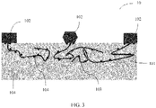
- a ceramic resin composite housing 10 provided in the embodiments of the present invention includes a ceramic member 101 and a resin member 102 that is molded on the ceramic member 101 through injection molding.
- a surface that is of the ceramic member 101 and that is bonded with the resin member 102 includes a plurality of long-strip-shaped holes 103 extending from the surface of the ceramic member 101 to the inside of the ceramic member.
- the long-strip-shaped holes 103 have an open hole structure. Pore sizes of the long-strip-shaped holes 103 range from 700 nm to 500 ⁇ m. Lengths of at least some of the long-strip-shaped holes 103 are greater than 100 ⁇ m and less than or equal to 1000 ⁇ m.
- the long-strip-shaped holes 103 are filled with a resin material that constitutes the resin member 102.
- the ceramic resin composite housing provided in the embodiments of the present invention, integrated molding of ceramic and resin can be completed by using a mature injection molding process, and the composite housing has an appearance and a texture of a ceramic material, and also has a fine structure formed by the resin material.
- the ceramic member includes the micron-level and/or submicron-level long-strip-shaped holes that extend from the surface to the inside, and the resin material infiltrates into the long-strip-shaped holes, so that a micro-level tight bond is formed on the bonding interface between the ceramic member and the resin member, and a bonding strength is high.
- the resin material that infiltrates into the ceramic member also has a similar fiber toughening effect on the ceramic member, and interface energy required for cracking the ceramic member is improved through a pull-out effect. Therefore, compared with a pure ceramic substrate, the ceramic resin composite housing in the embodiments of the present invention has better toughness, and has a lower probability of damage in a case of impact load such as falling.
- the long-strip-shaped holes in the embodiments of the present invention do not significantly damage integrity of the ceramic, and a mechanical property of a ceramic substrate is less weakened.
- the ceramic resin composite housing in the embodiments of the present invention has a lower density, which is beneficial to weight reduction of a terminal device.
- the long-strip-shaped holes 103 are formed through loss on ignition of organic fibers.
- the long-strip-shaped fiber-like holes that extend from the surface of the ceramic to the inside of the ceramic are formed in the ceramic member by using a fiber loss-on-ignition method.
- the long-strip-shaped hole can form an undercut structure, and its glue pulling effect is better than that of a granular hole. Therefore, the strength of bonding between the ceramic and the resin can be improved.
- the long-strip-shaped holes can activate and connect to internal closed holes of the ceramic member, the holes are filled with the resin material (as shown in FIG. 3 ) after the injection molding, and there is the pull-out effect in the damage process, thereby further improving the bonding strength.
- the long-strip-shaped holes 103 extend in a winding manner from the surface of the ceramic member 101 to the inside of the ceramic member 102.
- the resin material infiltrates into the long-strip-shaped holes that extend in the winding manner, which is more beneficial to improvement of the strength of interface bonding between the ceramic and the resin through the pull-out effect.
- the long-strip-shaped hole 103 has an open hole structure, where an open end of the long-strip-shaped hole 103 is located on the surface that is of the ceramic member 101 and that is bonded with the resin member 102, and a closed end of the long-strip-shaped hole 103 is located inside the ceramic member 101.
- the resin material may enter the long-strip-shaped hole from the open end.
- the long-strip-shaped holes are formed through the loss on ignition of the fibers. Therefore, a pore size of the long-strip-shaped hole is determined by a thickness of the fiber, and the pore size is easy to be controlled.
- the pore sizes of the plurality of long-strip-shaped holes 103 may be the same, or may be different.
- pore sizes at all positions of the long-strip-shaped holes 103 may be the same or basically the same; or the pore sizes of the long-strip-shaped holes gradually increase as the long-strip-shaped holes extend from the surface of the ceramic member to the inside of the ceramic member; or the pore sizes of the long-strip-shaped holes gradually decrease as the long-strip-shaped holes extend from the surface of the ceramic member to the inside of the ceramic member.
- the pore sizes at all positions are the same or basically the same, which facilitates preparation.
- the pore sizes gradually increase as the long-strip-shaped holes extend from the surface of the ceramic member to the inside of the ceramic member, which helps form better undercut structures and improve the bonding strength.
- the pore sizes gradually decrease as the long-strip-shaped holes extend from the surface of the ceramic member to the inside of the ceramic member, which facilitates infiltration of the resin material, so that the resin smoothly fills the holes.
- the foregoing three forms of the long-strip-shaped holes may exist at the same time, or only one or two of the foregoing three forms may exist.
- the pore sizes of the long-strip-shaped holes change irregularly as the long-strip-shaped holes extend from the surface of the ceramic member to the inside of the ceramic member.
- the pore sizes of some or all of the long-strip-shaped holes 103 range from 15 ⁇ m to 500 ⁇ m.
- a volume proportion of the plurality of long-strip-shaped holes in the ceramic member is 1% to 35%. Further, the volume proportion of the plurality of long-strip-shaped holes in the ceramic member may be controlled to be between 10% and 25%. An appropriate volume proportion of the long-strip-shaped holes can ensure a high strength of bonding between the ceramic and the resin, and enable the ceramic member body to have a high strength.
- an area proportion of the plurality of long-strip-shaped holes on the surface that is of the ceramic member and that is bonded with the resin member ranges from 1% to 60%. Further, the area proportion of the plurality of long-strip-shaped holes may range from 10% to 30%. An appropriate area proportion of the long-strip-shaped holes can ensure a high strength of bonding between the ceramic and the resin.
- the plurality of long-strip-shaped holes are evenly distributed on the surface that is of the ceramic member and that is bonded with the resin member.
- a small quantity of long-strip-shaped holes having a closed hole structure may also exist inside the ceramic member due to a fiber distribution problem. That is, when some fibers are distributed only inside the ceramic, and do not extend to the ceramic surface, long-strip-shaped holes having a closed hole structure are formed inside the ceramic after the loss on ignition of the fibers.
- a closed hole refers to a cavity and a pore channel in a porous solid that are not connected to the outside
- an open hole refers to a cavity and a pore channel in a porous solid that are connected to the outside.
- the surface and the inside of the ceramic member may further include a plurality of non-long-strip-shaped holes 104.
- These non-long-strip-shaped holes are not formed through loss on ignition of fibers, but are inevitably generated due to a raw material or another reason in a firing process of the ceramic.
- Shapes of the non-long-strip-shaped holes are not limited, and may be regular or irregular shapes.
- the non-long-strip-shaped holes may be spherical or quasi-spherical holes, and pore sizes of the non-long-strip-shaped holes are mostly micron-level or submicron-level.
- non-long-strip-shaped holes 104 are distributed on the surface of the ceramic member and have an open hole structure, and some of these non-long-strip-shaped holes 104 are distributed inside the ceramic member and have a closed hole structure.
- the long-strip-shaped holes 103 having the open hole structure can activate and connect to some of the closed non-long-strip-shaped holes 104 inside the ceramic member, so that the closed non-long-strip-shaped holes are also filled with the resin material after the injection molding, thereby further improving the bonding strength.
- a total volume proportion of various holes inside the ceramic member is controlled to not exceed 40%. Further, a total volume proportion of various holes inside the ceramic member is controlled to not exceed 30%. Furthermore, a total volume proportion of various holes inside the ceramic member may not exceed 25%.
- a material of the ceramic member includes one or more of an oxide ceramic material, a nitride ceramic material, and a carbide ceramic material.
- the oxide ceramic material may be, for example, one or more of alumina, zirconia, silicon oxide, and kaolin;
- the nitride ceramic may be, for example, one or more of silicon nitride and boron nitride;
- the carbide ceramic material may be, for example, silicon carbide.
- the ceramic member may be a ceramic flat plate with a thickness of 0.25 mm to 0.7 mm.
- a material of the resin member is thermoplastic resin.
- the resin material can be bonded to the ceramic member through the mature injection molding process, which facilitates molding of a complex and fine structure, has a comparatively high degree of freedom in structural design, and features convenient processing and low costs.
- the thermoplastic resin may be one or more of polyester resin and polyamide resin, and specifically the polyamide resin may be aliphatic polyamide resin, aromatic polyamide resin, or a mixture of aliphatic polyamide resin and aromatic polyamide resin.
- the resin member may further include a reinforcing component, where the reinforcing component may include one or more of glass fibers, carbon fibers, glass flakes, calcium carbonate, magnesium carbonate, silica, and talc.
- specific shapes and structures of the ceramic member and the resin member are not limited, and the ceramic member and the resin member may be molded according to an actual product requirement.
- the resin member may be of an integrated structure, or may include a plurality of separate structures bonded to the surface of the ceramic member.
- FIG. 4 Aand FIG. 4B are schematic structural diagrams of a rear cover 15 of a mobile phone according to a specific embodiment of the present invention.
- the rear cover has both a warm and jade-like ceramic member 151 and a resin member 152 that has a fine structure.
- the ceramic member 151 forms a main appearance body of the rear cover of the mobile phone, and presents a ceramic appearance and texture; and the resin member 152 forms functional structures of a frame of the rear cover and an inner side of the rear cover, which facilitates fine processing.
- the ceramic member is less exposed to direct impact, reducing a probability of damage.
- a micron-level and/or submicron-level bonding is implemented on a surface between the ceramic member 151 and the resin member 152, and a bonding strength is high.
- resin that infiltrates into the ceramic member 151 can also have a fiber toughening effect, which further optimizes resistance of the composite housing to impact and damage.
- the ceramic resin composite housing provided in the embodiments of the present invention includes the ceramic member and the resin member that are composited into an integrated structure, where the ceramic member includes the micron-level and/or submicron-level long-strip-shaped holes that extend from the surface to the inside, and the resin material partially infiltrates into the long-strip-shaped holes, so that a micro-level tight bond is formed on the bonding interface between the ceramic member and the resin member, and a bonding strength is high.
- the resin material that infiltrates into the ceramic member also toughens the ceramic member.
- the long-strip-shaped holes have small pore sizes. Therefore, integrity of the ceramic is not significantly damaged, and a mechanical property of a ceramic substrate is less weakened.
- an embodiment of the present invention further provides a preparation method of a ceramic resin composite housing, including the following steps.
- S101 Prepare a ceramic member with a preset shape by using organic fibers as a pore-forming agent, where a surface that is of the ceramic member and on which injection molding is pre-performed includes a plurality of long-strip-shaped holes that extend from the surface to the inside of the ceramic member, the long-strip-shaped holes are formed through loss on ignition of the organic fibers, the long-strip-shaped holes have an open hole structure, pore sizes of the long-strip-shaped holes range from 700 nm to 500 ⁇ m, and lengths of at least some of the long-strip-shaped holes are greater than 100 ⁇ m and less than or equal to 1000 ⁇ m.
- FIG. 5 is a schematic structural diagram of a ceramic member including long-strip-shaped holes, where 103 is the long-strip-shaped hole having the open hole structure.
- S102 Perform impregnation on the ceramic member by using an aqueous solution that includes a nitrogen compound to enable the aqueous solution that includes the nitrogen compound to enter the long-strip-shaped holes, and then perform drying to attach a layer of the nitrogen compound to inner walls of the long-strip-shaped holes.
- FIG. 6 is a schematic diagram of composition of ceramic and resin in an injection molding process, where 105 is a runner in which the resin liquid flows in the injection molding process.
- an artificial fiber and/or a natural fiber on which loss on ignition can be performed may be selected and used as the organic fiber.
- the organic fiber may be but is not limited to one or more of a nylon fiber, an explosion-proof fiber, and natural wood chips. Diameters of the organic fibers range from 700 nm to 500 ⁇ m, and lengths of at least some of the organic fibers are greater than 100 ⁇ m and less than or equal to 1000 ⁇ m. The diameters and lengths of the organic fibers directly determine pore sizes and lengths of the long-strip-shaped holes that are formed finally. A quantity of organic fibers added is controlled to be between 0.1 wt% and 5 wt%.
- the ceramic member is prepared by using the organic fibers as the pore-forming agent, and sizes of the holes in the ceramic member are easy to be controlled.
- the ceramic member does not include macroscopic holes, but instead includes a large quantity of micron-level and/or submicron-level long-strip-shaped holes leading to the inside of the ceramic substrate.
- a specific preparation method of the ceramic member with the preset shape is not limited.
- the ceramic member with the preset shape may be prepared by using one or more of an injection molding method, a tape casting method, a 3D printing method, a hot pressing method, and a slurry dipping and sanding method, where a layer-by-layer slurry dipping method can better control distribution of holes, and regulate a distribution gradient of the holes along a thickness direction of the ceramic member.
- a proportion of holes inside the ceramic is high, and a proportion of holes on the surface of the ceramic is low, so that an undercut structure is stronger.
- regulation may be performed according to specific requirements of a product.
- a specific preparation process of the ceramic member with the preset shape may be as follows: mixing ceramic powder, the organic fibers, and a bonding agent to prepare a ceramic member green body, and sintering the ceramic member green body to obtain the ceramic member.
- a particle size of the ceramic powder is between 0.1 ⁇ m and 100 ⁇ m.
- a type of the ceramic powder may be one or more of an oxide ceramic material, a nitride ceramic material, and a carbide ceramic material.
- the oxide ceramic material may be, for example, one or more of alumina, zirconia, silicon oxide, and kaolin (essentially an aluminum silicon oxide compound);
- the nitride ceramic may be, for example, one or more of silicon nitride and boron nitride;
- the carbide ceramic material may be, for example, silicon carbide.
- Silica sol, zirconium sol, water glass, zirconium diacetate, or the like may be selected and used as the bonding agent. After the preparation of the green body is completed, the green body can be roasted at 850°C to 1550°C for 30 minutes to 24 hours and then cooled in a furnace to complete the preparation of the ceramic member.
- the foregoing roasting conditions are only common roasting parameters, and a roasting parameter of special ceramic may not fall within the foregoing range.
- the ceramic member may be a ceramic flat plate with a thickness of 0.25 mm to 0.7 mm.
- alumina powder with a median particle diameter of 2 ⁇ m is selected and used as the ceramic powder; 30 wt% silica sol is selected and used as the bonding agent; and nylon fibers with a diameter of 10 ⁇ m are selected and used as the organic fibers, where lengths of at least some of the nylon fibers are greater than 100 ⁇ m and less than or equal to 200 ⁇ m, and a quantity of nylon fibers added is 1.2 wt%.
- the ceramic member is a flat plate with a thickness of 0.7 mm.
- the holes are formed inside the ceramic in the fiber loss-on-ignition manner; and the obtained holes can extend into the ceramic, are not limited to the surface of the ceramic, and can be distributed throughout the entire ceramic substrate if necessary.
- the method does not require use of various types of acids and alkalis, and achieves a good environmental protection effect.
- the fiber loss-on-ignition process is implemented synchronously in the ceramic roasting process, which has a good energy saving effect.
- the long-strip-shaped holes are open holes, the pore sizes of the long-strip-shaped holes range from 700 nm to 500 ⁇ m, and lengths of at least some of the long-strip-shaped holes are greater than 100 ⁇ m and less than or equal to 1000 ⁇ m.
- the long-strip-shaped holes of specific lengths can better extend into the ceramic.
- the nitrogen compound includes one or more of ammonia, a hydrazine compound and its derivative, and a water-soluble amine.
- a concentration of the aqueous solution that includes the nitrogen compound may range from 1 wt% to 35 wt%, and specifically may be, for example, 5 wt%, 10 wt%, 20 wt%, 30 wt%, or 35 wt%.
- Impregnation duration may be 2 minutes to 60 minutes, and specific duration is determined based on morphology of the holes in the ceramic member. Deeper holes and smaller pore sizes require longer impregnation duration. For example, the impregnation duration may be 20 minutes, 30 minutes, 40 minutes, 5 minutes, or 60 minutes.
- a vacuum condition and/or ultrasonic vibration auxiliary treatment are/is used in the impregnation process.
- the ultrasonic treatment can also promote a release of gas from the long-strip-shaped holes that have the open hole structure, thereby facilitating the entry of the aqueous solution that includes the nitrogen compound into the holes.
- a manner of performing drying on the ceramic member obtained after the impregnation may be air drying or freeze drying, where a temperature of the air drying ranges from 10°C to 80°C, a wind speed may range from 3 m/s to 8 m/s, and duration may range from 10 hours to 24 hours. Control of an appropriate temperature can reduce loss of a nitrogen element.
- side-blowing air drying may be used. A wind speed of side blowing is 5 m/s, and duration is 24 hours. According to a principle of hydromechanics, side blowing achieves a better effect when deep holes are dried.
- a layer of the nitrogen compound is attached to the inner walls of the holes after the drying is performed. In the injection molding process, the nitrogen compound has an exothermic reaction with the resin to promote infiltration of the resin liquid into the holes.
- the dried ceramic member is placed into an injection molding mold for injection molding.
- An injection molding material is thermoplastic resin. This type of resin can have an exothermic reaction between esters and amines, with the nitrogen compound on the inner walls of the holes.
- the thermoplastic resin may be one or more of polyester resin and polyamide resin, and specifically the polyamide resin may be aliphatic polyamide resin, aromatic polyamide resin, or a mixture of aliphatic polyamide resin and aromatic polyamide resin.
- Specific injection molding parameters can be determined based on a type of a raw resin material. Usually, an injection port temperature ranges from 220°C to 400°C, and a mold temperature ranges from 180°C to 400°C.
- the injection port temperature ranges from 295°C to 320°C
- the mold temperature ranges from 230°C to 260°C.
- the reinforcing component may include one or more of glass fibers, carbon fibers, glass flakes, calcium carbonate, magnesium carbonate, silica, and talc.
- 66 wt% polybutylene terephthalate (PBT) and 34 wt% glass fibers are selected and used as a resin member material.
- the injection port temperature is 330°C
- the mold temperature is 260°C.
- a machining method such as CNC (Computerised Numerical Control, computer numerical control) may be used to perform fine structure processing on the resin part of the composite housing to obtain the target composite housing.
- CNC Computerised Numerical Control, computer numerical control
- the manner of bonding the ceramic and resin in the embodiments of the present invention may be further combined with another existing bonding manner, for example, further combined with riveting and macro-size hole glue pulling.
- the preparation method provided in the embodiments of the present invention implements a tight connection between the ceramic and the resin under dual effects of physical embedding and a chemical reaction.
- the long-strip-shaped holes that extend to the inside of the ceramic member are prepared through the loss on ignition of the organic fibers, and the resin infiltrates into the long-strip-shaped holes to enhance bonding of the resin and the ceramic.
- the holes are enriched with the nitrogen compound through the impregnation; and in the injection molding process, the nitrogen compound has an exothermic reaction with the resin that infiltrates into the holes, to provide heat to keep the front end of the resin liquid flow used for injection molding continuously in a low-viscosity flow state.
- the resin infiltrates into the long-strip-shaped holes smoothly, and the following problem is resolved to some extent:
- the resin cannot smoothly infiltrate into the holes because of an increase in viscosity of the front end of the resin liquid flow due to cooling.
- the holes are formed through the loss on ignition of the organic fibers. Integrity of a ceramic structure is not significantly damaged, and a strong acid and a strong alkali are not required. The loss on ignition of the fibers is completed in a ceramic sintering process, which is environment-friendly and energy-saving.
Landscapes
- Engineering & Computer Science (AREA)
- Manufacturing & Machinery (AREA)
- Signal Processing (AREA)
- Mechanical Engineering (AREA)
- Chemical & Material Sciences (AREA)
- Materials Engineering (AREA)
- Injection Moulding Of Plastics Or The Like (AREA)
- Casings For Electric Apparatus (AREA)
- Laminated Bodies (AREA)
Abstract
Description
- This application claims priority to
Chinese Patent Application No. 201911424962.9, filed with the Chinese Patent Office on December 30, 2019 - Embodiments of the present invention relate to the field of terminal housing technologies, and in particular, to a ceramic resin composite housing, a preparation method thereof, and a terminal.
- A ceramic material has good mechanical and electrical properties, and has a warm and jade-like texture in appearance. When used in a terminal device housing, the ceramic material can improve product performance and user experience. However, processing of the ceramic material and molding of a fine structure are difficult, resulting in a low yield rate and high costs. Resin has advantages of a good comprehensive mechanical property and easy molding, which facilitates fine structure molding and features considerable design freedom. In addition, a resin material has small density, and has a good weight reduction function when the resin material is used for molding a housing of an intelligent terminal. To comprehensively utilize the advantages of the two materials, the ceramic material and the resin material are used to form a composite in the industry. However, the ceramic material and the resin material differ greatly in physical and chemical properties. Consequently, it is difficult to achieve a micro-level tight connection, and a bonding strength of a bonding interface between the ceramic material and the resin material is not high.
- In view of this, embodiments of the present invention provide a ceramic resin composite housing, to resolve an existing problem of a low strength of bonding between ceramic and resin to some extent.
- Specifically, a first aspect of the embodiments of the present invention provides a ceramic resin composite housing, including a ceramic member and a resin member that is molded on the ceramic member through injection molding. A surface that is of the ceramic member and that is bonded with the resin member includes a plurality of long-strip-shaped holes extending from the surface to the inside of the ceramic member. The long-strip-shaped holes have an open hole structure. Pore sizes of the long-strip-shaped holes range from 700 nm to 500 µm, and lengths of at least some of the long-strip-shaped holes are greater than 100 µm and less than or equal to 1000 µm. The long-strip-shaped holes are filled with a resin material that constitutes the resin member.
- In an implementation of the present invention, the long-strip-shaped holes are formed through loss on ignition of organic fibers, and the long-strip-shaped holes extend in a winding manner from the surface of the ceramic member to the inside of the ceramic member.
- In an implementation of the present invention, pore sizes at all positions of the long-strip-shaped holes are the same or basically the same.
- In an implementation of the present invention, the pore sizes of the long-strip-shaped holes gradually increase as the long-strip-shaped holes extend from the surface of the ceramic member to the inside of the ceramic member.
- In an implementation of the present invention, the pore sizes of the long-strip-shaped holes gradually decrease as the long-strip-shaped holes extend from the surface of the ceramic member to the inside of the ceramic member.
- In an implementation of the present invention, a volume proportion of the plurality of long-strip-shaped holes in the ceramic member is 1% to 35%.
- In an implementation of the present invention, an area proportion of the plurality of long-strip-shaped holes on the surface that is of the ceramic member and that is bonded with the resin member ranges from 1% to 60%.
- In an implementation of the present invention, the pore sizes of some or all of the long-strip-shaped holes range from 15 µm to 500 µm.
- In an implementation of the present invention, the plurality of long-strip-shaped holes are evenly distributed on the surface that is of the ceramic member and that is bonded with the resin member.
- In an implementation of the present invention, the surface that is of the ceramic member and that is bonded with the resin member further includes a plurality of non-long-strip-shaped holes, where the non-long-strip-shaped holes are filled with the resin material that constitutes the resin member.
- In an implementation of the present invention, a material of the ceramic member includes one or more of an oxide ceramic material, a nitride ceramic material, and a carbide ceramic material.
- In an implementation of the present invention, a material of the resin member is thermoplastic resin.
- In an implementation of the present invention, the resin member further includes a reinforcing component, where the reinforcing component includes one or more of glass fibers, carbon fibers, glass flakes, calcium carbonate, magnesium carbonate, silica, and talc.
- In an implementation of the present invention, the resin member may be of an integrated structure, or may include a plurality of separate structures bonded to the surface of the ceramic member.
- The ceramic resin composite housing provided in the first aspect of the embodiments of the present invention includes the ceramic member and the resin member that are composited into an integrated structure, where the ceramic member includes the micron-level and/or submicron-level long-strip-shaped holes that extend from the surface to the inside, and a part of the resin material infiltrates into the long-strip-shaped holes, so that a micro-level tight bond is formed on the bonding interface between the ceramic member and the resin member, and a bonding strength is high. The resin material that infiltrates into the ceramic member also toughens the ceramic member. In addition, the long-strip-shaped holes have small pore sizes. Therefore, integrity of the ceramic is not significantly damaged, and a mechanical property of a ceramic substrate is less weakened.
- According to a second aspect, the embodiments of the present invention further provide a preparation method of a ceramic resin composite housing, including:
- preparing a ceramic member with a preset shape by using organic fibers as a pore-forming agent, where a surface that is of the ceramic member and on which injection molding is pre-performed includes a plurality of long-strip-shaped holes that extend from the surface to the inside of the ceramic member, the long-strip-shaped holes are formed through loss on ignition of the organic fibers, the long-strip-shaped holes have an open hole structure, pore sizes of the long-strip-shaped holes range from 700 nm to 500 µm, and lengths of at least some of the long-strip-shaped holes are greater than 100 µm and less than or equal to 1000 µm;
- performing impregnation on the ceramic member by using an aqueous solution that includes a nitrogen compound to enable the aqueous solution that includes the nitrogen compound to enter the long-strip-shaped holes, and then performing drying to attach a layer of the nitrogen compound to inner walls of the long-strip-shaped holes; and
- performing injection molding on the dried ceramic member, enabling a resin liquid to enter the long-strip-shaped holes to have an exothermic reaction with the nitrogen compound, and performing fine structure processing on a resin part after the injection molding is completed, to obtain a ceramic resin composite housing.
- In an implementation of the present invention, the nitrogen compound includes one or more of ammonia, a hydrazine compound and its derivative, and a water-soluble amine.
- In an implementation of the present invention, a specific method for the preparing a ceramic member with a preset shape by using organic fibers as a pore-forming agent includes one or more of an injection molding method, a tape casting method, a 3D printing method, a hot pressing method, and a slurry dipping and sanding method.
- In an implementation of the present invention, the preparing a ceramic member with a preset shape by using organic fibers as a pore-forming agent includes: mixing ceramic powder, the organic fibers, and a bonding agent to prepare a ceramic member green body, and sintering the ceramic member green body to obtain the ceramic member.
- In an implementation of the present invention, the organic fiber includes at least one of an artificial fiber and a natural fiber on which loss on ignition can be performed.
- In an implementation of the present invention, the impregnation process is performed in a vacuum condition.
- In an implementation of the present invention, ultrasonic vibration is performed in the impregnation process.
- In an implementation of the present invention, a manner of the drying is air drying or freeze drying, and a temperature for the air drying ranges from 10°C to 80°C.
- The preparation method provided in the second aspect of the embodiments of the present invention implements a tight connection between ceramic and resin under dual effects of physical embedding and a chemical reaction. On the one hand, the long-strip-shaped holes that extend to the inside of the ceramic member are prepared through the loss on ignition of the organic fibers, and the resin infiltrates into the long-strip-shaped holes to enhance bonding of the resin and the ceramic. On the other hand, the nitrogen compound is attached to the inner walls of the long-strip-shaped holes through the impregnation; and in the injection molding process, the nitrogen compound has an exothermic reaction with the resin that infiltrates into the holes, to provide heat to keep a front end of a resin liquid flow continuously in a low-viscosity flow state. In this way, the resin infiltrates into the long-strip-shaped holes smoothly, and the following problem is avoided: The resin cannot smoothly infiltrate into the holes because of an increase in viscosity of the front end of the resin liquid flow due to cooling. In addition, in the embodiments of the present invention, the holes are formed through the loss on ignition of the organic fibers. Integrity of a ceramic structure is not significantly damaged, and a strong acid and a strong alkali are not required. The loss on ignition of the fibers is completed in the ceramic sintering process, which is environment-friendly and energy-saving.
- The embodiments of the present invention further provide a terminal, including the ceramic resin composite housing according to the first aspect of the embodiments of the present invention. The ceramic resin composite housing may serve as a housing structure, such as a front cover, a middle frame, or a rear cover, of the terminal. The housing of the terminal provided in the embodiments of the present invention has both a ceramic texture and appearance, and an internal fine structure formed by resin, thereby improving market competitiveness.
- The embodiments of the present invention further provide a mobile phone, including a display, a housing assembled on an outer side of the mobile phone, and a mainboard and a battery that are located inside the housing. The entire or a part of the housing is the ceramic resin composite housing according to any implementation of the first aspect of the embodiments of the present invention.
- In an implementation of the present invention, the housing includes a rear cover assembled on a rear side of the mobile phone. Alternatively, the housing includes a front cover assembled on a front side of the mobile phone. Alternatively, the housing includes a middle frame assembled in the mobile phone. Alternatively, the housing includes one or more of a rear cover, a front cover, and a middle frame.
- The middle frame is located between the front cover and the rear cover of the mobile phone. Alternatively, the middle frame is located between the display and the rear cover of the mobile phone.
- In an implementation of the present invention, the rear cover and the middle frame are of an integrated structure or separate structures.
- In an implementation of the present invention, the rear cover is a ceramic resin composite housing, where a ceramic member forms a main appearance body of the rear cover of the mobile phone, and presents a ceramic appearance and texture, and a resin member forms functional structures of a frame of the rear cover and an inner side of the rear cover. Therefore, the rear cover has both a ceramic texture and appearance and an internal fine functional structure.
-
-
FIG. 1 is a schematic structural diagram of amobile phone 100 according to an embodiment of the present invention; -
FIG. 2 is a schematic structural diagram of amobile phone housing 11 according to an embodiment of the present invention; -
FIG. 3 is a schematic structural diagram of a ceramic resin composite housing according to an embodiment of the present invention; -
FIG. 4A andFIG. 4B are partial schematic structural diagrams of a front surface and a rear surface of a rear cover of a mobile phone respectively according to an embodiment of the present invention; -
FIG. 5 is a schematic structural diagram of a ceramic member prepared in step S101 of a preparation method according to an embodiment of the present invention; and -
FIG. 6 is a schematic diagram of composition of ceramic and resin in an injection molding process instep S 102 of a preparation method according to an embodiment of the present invention. - The following describes the embodiments of the present invention with reference to the accompanying drawings in the embodiments of the present invention.
- The embodiments of the present invention provide a ceramic resin composite housing that may be applied to a housing of a terminal, so that the terminal housing has both a ceramic appearance and texture, and an internal fine structure formed by resin, thereby improving market competitiveness of a terminal product. The terminal may be a mobile phone, or may be an electronic product such as a tablet computer, a notebook computer, a portable computer, or an intelligent wearable product. A part of the terminal housing or the entire terminal housing may be the ceramic resin composite housing provided in the embodiments of the present invention. The terminal housing is an external structural member that is configured to protect internal components of the terminal and can be directly seen and touched by a user.
- A mobile phone is used as an example.
FIG. 1 is a schematic structural diagram of amobile phone 100 according to an embodiment of the present invention. Themobile phone 100 includes ahousing 11 assembled on an outer side of the mobile phone, and components such as a mainboard and a battery that are located inside thehousing 11. As shown inFIG. 2 , thehousing 11 may specifically include afront cover 12 assembled on a front side (that is, a display side) of the mobile phone, or may include arear cover 13 assembled on a rear side of the mobile phone. In some implementations of the present invention, thehousing 11 may further include amiddle frame 14 located between thefront cover 12 and therear cover 13, and themiddle frame 14 is configured to bear components such as the mainboard and the battery. In an implementation of the present invention, thefront cover 12, therear cover 13, and/or themiddle frame 14 are/is integrally the ceramic resin composite housing provided in the embodiments of the present invention, or a part of thefront cover 12, therear cover 13, and/or themiddle frame 14 is the ceramic resin composite housing. For example, a part of therear cover 13 or a part of thefront cover 12 or themiddle frame 14 is the ceramic resin composite housing. In some implementations of the present invention, therear cover 13 and themiddle frame 14 may be an integrated structure. In some other implementations of the present invention, therear cover 13 and themiddle frame 14 may alternatively be of separate structures. The mobile phone further includes a display. In a mobile phone with a bezel-less screen, a housing usually does not include a front cover, and a middle frame is located between a display and a rear cover. Alternatively, in some mobile phones with a bezel-less screen, a housing may not include an exposed middle frame. - As shown in
FIG. 3 , a ceramic resincomposite housing 10 provided in the embodiments of the present invention includes aceramic member 101 and aresin member 102 that is molded on theceramic member 101 through injection molding. A surface that is of theceramic member 101 and that is bonded with theresin member 102 includes a plurality of long-strip-shapedholes 103 extending from the surface of theceramic member 101 to the inside of the ceramic member. The long-strip-shapedholes 103 have an open hole structure. Pore sizes of the long-strip-shapedholes 103 range from 700 nm to 500 µm. Lengths of at least some of the long-strip-shapedholes 103 are greater than 100 µm and less than or equal to 1000 µm. The long-strip-shapedholes 103 are filled with a resin material that constitutes theresin member 102. - In the ceramic resin composite housing provided in the embodiments of the present invention, integrated molding of ceramic and resin can be completed by using a mature injection molding process, and the composite housing has an appearance and a texture of a ceramic material, and also has a fine structure formed by the resin material. The ceramic member includes the micron-level and/or submicron-level long-strip-shaped holes that extend from the surface to the inside, and the resin material infiltrates into the long-strip-shaped holes, so that a micro-level tight bond is formed on the bonding interface between the ceramic member and the resin member, and a bonding strength is high. In addition, the resin material that infiltrates into the ceramic member also has a similar fiber toughening effect on the ceramic member, and interface energy required for cracking the ceramic member is improved through a pull-out effect. Therefore, compared with a pure ceramic substrate, the ceramic resin composite housing in the embodiments of the present invention has better toughness, and has a lower probability of damage in a case of impact load such as falling. The long-strip-shaped holes in the embodiments of the present invention do not significantly damage integrity of the ceramic, and a mechanical property of a ceramic substrate is less weakened. In addition, compared with the pure ceramic substrate, the ceramic resin composite housing in the embodiments of the present invention has a lower density, which is beneficial to weight reduction of a terminal device.
- In an implementation of the present invention, the long-strip-shaped
holes 103 are formed through loss on ignition of organic fibers. The long-strip-shaped fiber-like holes that extend from the surface of the ceramic to the inside of the ceramic are formed in the ceramic member by using a fiber loss-on-ignition method. In a macroscopic view, the long-strip-shaped hole can form an undercut structure, and its glue pulling effect is better than that of a granular hole. Therefore, the strength of bonding between the ceramic and the resin can be improved. In a microscopic view, the long-strip-shaped holes can activate and connect to internal closed holes of the ceramic member, the holes are filled with the resin material (as shown inFIG. 3 ) after the injection molding, and there is the pull-out effect in the damage process, thereby further improving the bonding strength. - In an implementation of the present invention, the long-strip-shaped
holes 103 extend in a winding manner from the surface of theceramic member 101 to the inside of theceramic member 102. The resin material infiltrates into the long-strip-shaped holes that extend in the winding manner, which is more beneficial to improvement of the strength of interface bonding between the ceramic and the resin through the pull-out effect. - In an implementation of the present invention, the long-strip-shaped
hole 103 has an open hole structure, where an open end of the long-strip-shapedhole 103 is located on the surface that is of theceramic member 101 and that is bonded with theresin member 102, and a closed end of the long-strip-shapedhole 103 is located inside theceramic member 101. The resin material may enter the long-strip-shaped hole from the open end. In an embodiment of the present invention, the long-strip-shaped holes are formed through the loss on ignition of the fibers. Therefore, a pore size of the long-strip-shaped hole is determined by a thickness of the fiber, and the pore size is easy to be controlled. In an implementation of the present invention, the pore sizes of the plurality of long-strip-shapedholes 103 may be the same, or may be different. - In an implementation of the present invention, pore sizes at all positions of the long-strip-shaped
holes 103 may be the same or basically the same; or the pore sizes of the long-strip-shaped holes gradually increase as the long-strip-shaped holes extend from the surface of the ceramic member to the inside of the ceramic member; or the pore sizes of the long-strip-shaped holes gradually decrease as the long-strip-shaped holes extend from the surface of the ceramic member to the inside of the ceramic member. The pore sizes at all positions are the same or basically the same, which facilitates preparation. The pore sizes gradually increase as the long-strip-shaped holes extend from the surface of the ceramic member to the inside of the ceramic member, which helps form better undercut structures and improve the bonding strength. The pore sizes gradually decrease as the long-strip-shaped holes extend from the surface of the ceramic member to the inside of the ceramic member, which facilitates infiltration of the resin material, so that the resin smoothly fills the holes. In an embodiment of the present invention, the foregoing three forms of the long-strip-shaped holes may exist at the same time, or only one or two of the foregoing three forms may exist. Certainly, in some other implementations of the present invention, it may further be that the pore sizes of the long-strip-shaped holes change irregularly as the long-strip-shaped holes extend from the surface of the ceramic member to the inside of the ceramic member. - In an implementation of the present invention, to enable the resin material to better infiltrate into the long-strip-shaped holes, the pore sizes of some or all of the long-strip-shaped
holes 103 range from 15 µm to 500 µm. - In an implementation of the present invention, to ensure that the ceramic has a higher strength, a volume proportion of the plurality of long-strip-shaped holes in the ceramic member is 1% to 35%. Further, the volume proportion of the plurality of long-strip-shaped holes in the ceramic member may be controlled to be between 10% and 25%. An appropriate volume proportion of the long-strip-shaped holes can ensure a high strength of bonding between the ceramic and the resin, and enable the ceramic member body to have a high strength.
- In an implementation of the present invention, to ensure a tight bond between the ceramic and the resin, an area proportion of the plurality of long-strip-shaped holes on the surface that is of the ceramic member and that is bonded with the resin member ranges from 1% to 60%. Further, the area proportion of the plurality of long-strip-shaped holes may range from 10% to 30%. An appropriate area proportion of the long-strip-shaped holes can ensure a high strength of bonding between the ceramic and the resin.
- In an implementation of the present invention, to form a better bond between the ceramic and the resin, the plurality of long-strip-shaped holes are evenly distributed on the surface that is of the ceramic member and that is bonded with the resin member.
- In an implementation of the present invention, because the long-strip-shaped holes are formed through the loss on ignition of the fibers, a small quantity of long-strip-shaped holes having a closed hole structure may also exist inside the ceramic member due to a fiber distribution problem. That is, when some fibers are distributed only inside the ceramic, and do not extend to the ceramic surface, long-strip-shaped holes having a closed hole structure are formed inside the ceramic after the loss on ignition of the fibers. A closed hole refers to a cavity and a pore channel in a porous solid that are not connected to the outside, and an open hole refers to a cavity and a pore channel in a porous solid that are connected to the outside.
- In an implementation of the present invention, the surface and the inside of the ceramic member may further include a plurality of non-long-strip-shaped
holes 104. These non-long-strip-shaped holes are not formed through loss on ignition of fibers, but are inevitably generated due to a raw material or another reason in a firing process of the ceramic. Shapes of the non-long-strip-shaped holes are not limited, and may be regular or irregular shapes. For example, the non-long-strip-shaped holes may be spherical or quasi-spherical holes, and pore sizes of the non-long-strip-shaped holes are mostly micron-level or submicron-level. Some of these non-long-strip-shapedholes 104 are distributed on the surface of the ceramic member and have an open hole structure, and some of these non-long-strip-shapedholes 104 are distributed inside the ceramic member and have a closed hole structure. As shown inFIG. 3 , the long-strip-shapedholes 103 having the open hole structure can activate and connect to some of the closed non-long-strip-shapedholes 104 inside the ceramic member, so that the closed non-long-strip-shaped holes are also filled with the resin material after the injection molding, thereby further improving the bonding strength. - In an implementation of the present invention, to ensure a strength of the ceramic, a total volume proportion of various holes inside the ceramic member is controlled to not exceed 40%. Further, a total volume proportion of various holes inside the ceramic member is controlled to not exceed 30%. Furthermore, a total volume proportion of various holes inside the ceramic member may not exceed 25%.
- In an implementation of the present invention, a material of the ceramic member includes one or more of an oxide ceramic material, a nitride ceramic material, and a carbide ceramic material. Specifically, the oxide ceramic material may be, for example, one or more of alumina, zirconia, silicon oxide, and kaolin; the nitride ceramic may be, for example, one or more of silicon nitride and boron nitride; and the carbide ceramic material may be, for example, silicon carbide. In an implementation of the present invention, the ceramic member may be a ceramic flat plate with a thickness of 0.25 mm to 0.7 mm.
- In an implementation of the present invention, a material of the resin member is thermoplastic resin. The resin material can be bonded to the ceramic member through the mature injection molding process, which facilitates molding of a complex and fine structure, has a comparatively high degree of freedom in structural design, and features convenient processing and low costs. Specifically, the thermoplastic resin may be one or more of polyester resin and polyamide resin, and specifically the polyamide resin may be aliphatic polyamide resin, aromatic polyamide resin, or a mixture of aliphatic polyamide resin and aromatic polyamide resin.
- In an implementation of the present invention, to optimize a mechanical property of the resin member, the resin member may further include a reinforcing component, where the reinforcing component may include one or more of glass fibers, carbon fibers, glass flakes, calcium carbonate, magnesium carbonate, silica, and talc.
- In an implementation of the present invention, specific shapes and structures of the ceramic member and the resin member are not limited, and the ceramic member and the resin member may be molded according to an actual product requirement. The resin member may be of an integrated structure, or may include a plurality of separate structures bonded to the surface of the ceramic member.
-
FIG. 4 AandFIG. 4B are schematic structural diagrams of arear cover 15 of a mobile phone according to a specific embodiment of the present invention. The rear cover has both a warm and jade-likeceramic member 151 and aresin member 152 that has a fine structure. In this embodiment, theceramic member 151 forms a main appearance body of the rear cover of the mobile phone, and presents a ceramic appearance and texture; and theresin member 152 forms functional structures of a frame of the rear cover and an inner side of the rear cover, which facilitates fine processing. In daily use, the ceramic member is less exposed to direct impact, reducing a probability of damage. In addition, a micron-level and/or submicron-level bonding is implemented on a surface between theceramic member 151 and theresin member 152, and a bonding strength is high. In addition, resin that infiltrates into theceramic member 151 can also have a fiber toughening effect, which further optimizes resistance of the composite housing to impact and damage. - The ceramic resin composite housing provided in the embodiments of the present invention includes the ceramic member and the resin member that are composited into an integrated structure, where the ceramic member includes the micron-level and/or submicron-level long-strip-shaped holes that extend from the surface to the inside, and the resin material partially infiltrates into the long-strip-shaped holes, so that a micro-level tight bond is formed on the bonding interface between the ceramic member and the resin member, and a bonding strength is high. The resin material that infiltrates into the ceramic member also toughens the ceramic member. In addition, the long-strip-shaped holes have small pore sizes. Therefore, integrity of the ceramic is not significantly damaged, and a mechanical property of a ceramic substrate is less weakened.
- Correspondingly, an embodiment of the present invention further provides a preparation method of a ceramic resin composite housing, including the following steps.
- S101: Prepare a ceramic member with a preset shape by using organic fibers as a pore-forming agent, where a surface that is of the ceramic member and on which injection molding is pre-performed includes a plurality of long-strip-shaped holes that extend from the surface to the inside of the ceramic member, the long-strip-shaped holes are formed through loss on ignition of the organic fibers, the long-strip-shaped holes have an open hole structure, pore sizes of the long-strip-shaped holes range from 700 nm to 500 µm, and lengths of at least some of the long-strip-shaped holes are greater than 100 µm and less than or equal to 1000 µm.
FIG. 5 is a schematic structural diagram of a ceramic member including long-strip-shaped holes, where 103 is the long-strip-shaped hole having the open hole structure. - S102: Perform impregnation on the ceramic member by using an aqueous solution that includes a nitrogen compound to enable the aqueous solution that includes the nitrogen compound to enter the long-strip-shaped holes, and then perform drying to attach a layer of the nitrogen compound to inner walls of the long-strip-shaped holes.
- S103: Perform injection molding on the dried ceramic member, enable a resin liquid to enter the long-strip-shaped holes to have an exothermic reaction with the nitrogen compound, and perform fine structure processing on a resin part after the injection molding is completed, to obtain a ceramic resin composite housing.
FIG. 6 is a schematic diagram of composition of ceramic and resin in an injection molding process, where 105 is a runner in which the resin liquid flows in the injection molding process. - In an implementation of the present invention, in step S101, an artificial fiber and/or a natural fiber on which loss on ignition can be performed may be selected and used as the organic fiber. Specifically, for example, the organic fiber may be but is not limited to one or more of a nylon fiber, an explosion-proof fiber, and natural wood chips. Diameters of the organic fibers range from 700 nm to 500 µm, and lengths of at least some of the organic fibers are greater than 100 µm and less than or equal to 1000 µm. The diameters and lengths of the organic fibers directly determine pore sizes and lengths of the long-strip-shaped holes that are formed finally. A quantity of organic fibers added is controlled to be between 0.1 wt% and 5 wt%. Addition of an appropriate quantity of organic fibers cannot only form sufficient holes, but also avoid excessive weakening of a ceramic substrate. The ceramic member is prepared by using the organic fibers as the pore-forming agent, and sizes of the holes in the ceramic member are easy to be controlled. The ceramic member does not include macroscopic holes, but instead includes a large quantity of micron-level and/or submicron-level long-strip-shaped holes leading to the inside of the ceramic substrate.
- In an implementation of the present invention, a specific preparation method of the ceramic member with the preset shape is not limited. The ceramic member with the preset shape may be prepared by using one or more of an injection molding method, a tape casting method, a 3D printing method, a hot pressing method, and a slurry dipping and sanding method, where a layer-by-layer slurry dipping method can better control distribution of holes, and regulate a distribution gradient of the holes along a thickness direction of the ceramic member. In some implementations of the present invention, it may be that a proportion of holes on the surface of the ceramic is high, and a proportion of holes inside the ceramic is low, so that injection molding is easy. In some other implementations of the present invention, it may alternatively be that a proportion of holes inside the ceramic is high, and a proportion of holes on the surface of the ceramic is low, so that an undercut structure is stronger. Specifically, regulation may be performed according to specific requirements of a product.
- In this embodiment of the present invention, a specific preparation process of the ceramic member with the preset shape may be as follows: mixing ceramic powder, the organic fibers, and a bonding agent to prepare a ceramic member green body, and sintering the ceramic member green body to obtain the ceramic member. A particle size of the ceramic powder is between 0.1 µm and 100 µm. A type of the ceramic powder may be one or more of an oxide ceramic material, a nitride ceramic material, and a carbide ceramic material. Specifically, the oxide ceramic material may be, for example, one or more of alumina, zirconia, silicon oxide, and kaolin (essentially an aluminum silicon oxide compound); the nitride ceramic may be, for example, one or more of silicon nitride and boron nitride; and the carbide ceramic material may be, for example, silicon carbide. Silica sol, zirconium sol, water glass, zirconium diacetate, or the like may be selected and used as the bonding agent. After the preparation of the green body is completed, the green body can be roasted at 850°C to 1550°C for 30 minutes to 24 hours and then cooled in a furnace to complete the preparation of the ceramic member. Certainly, there are various types of ceramic, and roasting requirements of different ceramic vary greatly. Therefore, the foregoing roasting conditions are only common roasting parameters, and a roasting parameter of special ceramic may not fall within the foregoing range.
- In this embodiment of the present invention, the ceramic member may be a ceramic flat plate with a thickness of 0.25 mm to 0.7 mm.
- In a specific embodiment of the present invention, alumina powder with a median particle diameter of 2 µm is selected and used as the ceramic powder; 30 wt% silica sol is selected and used as the bonding agent; and nylon fibers with a diameter of 10 µm are selected and used as the organic fibers, where lengths of at least some of the nylon fibers are greater than 100 µm and less than or equal to 200 µm, and a quantity of nylon fibers added is 1.2 wt%. The ceramic member is a flat plate with a thickness of 0.7 mm.
- In an implementation of the present invention, the holes are formed inside the ceramic in the fiber loss-on-ignition manner; and the obtained holes can extend into the ceramic, are not limited to the surface of the ceramic, and can be distributed throughout the entire ceramic substrate if necessary. Second, the method does not require use of various types of acids and alkalis, and achieves a good environmental protection effect. Moreover, the fiber loss-on-ignition process is implemented synchronously in the ceramic roasting process, which has a good energy saving effect.
- In an implementation of the present invention, the long-strip-shaped holes are open holes, the pore sizes of the long-strip-shaped holes range from 700 nm to 500 µm, and lengths of at least some of the long-strip-shaped holes are greater than 100 µm and less than or equal to 1000 µm. The long-strip-shaped holes of specific lengths can better extend into the ceramic.
- In an implementation of the present invention, in step S102, the nitrogen compound includes one or more of ammonia, a hydrazine compound and its derivative, and a water-soluble amine. A concentration of the aqueous solution that includes the nitrogen compound may range from 1 wt% to 35 wt%, and specifically may be, for example, 5 wt%, 10 wt%, 20 wt%, 30 wt%, or 35 wt%. Impregnation duration may be 2 minutes to 60 minutes, and specific duration is determined based on morphology of the holes in the ceramic member. Deeper holes and smaller pore sizes require longer impregnation duration. For example, the impregnation duration may be 20 minutes, 30 minutes, 40 minutes, 5 minutes, or 60 minutes.
- In an embodiment of the present invention, to enable the aqueous solution that includes the nitrogen compound to enter the long-strip-shaped holes more smoothly and maintain full contact with inner walls of the long-strip-shaped holes, a vacuum condition and/or ultrasonic vibration auxiliary treatment are/is used in the impregnation process. The ultrasonic treatment can also promote a release of gas from the long-strip-shaped holes that have the open hole structure, thereby facilitating the entry of the aqueous solution that includes the nitrogen compound into the holes.
- In an implementation of the present invention, a manner of performing drying on the ceramic member obtained after the impregnation may be air drying or freeze drying, where a temperature of the air drying ranges from 10°C to 80°C, a wind speed may range from 3 m/s to 8 m/s, and duration may range from 10 hours to 24 hours. Control of an appropriate temperature can reduce loss of a nitrogen element. In a specific implementation of the present invention, side-blowing air drying may be used. A wind speed of side blowing is 5 m/s, and duration is 24 hours. According to a principle of hydromechanics, side blowing achieves a better effect when deep holes are dried. A layer of the nitrogen compound is attached to the inner walls of the holes after the drying is performed. In the injection molding process, the nitrogen compound has an exothermic reaction with the resin to promote infiltration of the resin liquid into the holes.
- In an implementation of the present invention, in step S103, the dried ceramic member is placed into an injection molding mold for injection molding. An injection molding material is thermoplastic resin. This type of resin can have an exothermic reaction between esters and amines, with the nitrogen compound on the inner walls of the holes. Specifically, the thermoplastic resin may be one or more of polyester resin and polyamide resin, and specifically the polyamide resin may be aliphatic polyamide resin, aromatic polyamide resin, or a mixture of aliphatic polyamide resin and aromatic polyamide resin. Specific injection molding parameters can be determined based on a type of a raw resin material. Usually, an injection port temperature ranges from 220°C to 400°C, and a mold temperature ranges from 180°C to 400°C. Further, the injection port temperature ranges from 295°C to 320°C, and the mold temperature ranges from 230°C to 260°C. In an injection process, high-temperature resin melt with good fluidity enters the long-strip-shaped holes in the ceramic member under high pressure, and has an exothermic reaction between esters and amines, with the nitrogen compound on the inner walls of the holes. In this way, a temperature at a front end of a resin liquid flow does not drop sharply, and the front end can continuously remain in a lower-viscosity state for a long time, to smoothly enter the micron-level and submicron-level holes on the surface of the ceramic and inside the ceramic, and form micron-level and submicron-level embedding structures on an interface.
- To optimize a mechanical property of the resin, a specific amount of a reinforcing component may also be added to the resin. The reinforcing component may include one or more of glass fibers, carbon fibers, glass flakes, calcium carbonate, magnesium carbonate, silica, and talc.
- In a specific implementation of the present invention, 66 wt% polybutylene terephthalate (PBT) and 34 wt% glass fibers are selected and used as a resin member material. In the injection molding process, the injection port temperature is 330°C, and the mold temperature is 260°C.
- In an implementation of the present invention, after the injection molding process is completed, a machining method such as CNC (Computerised Numerical Control, computer numerical control) may be used to perform fine structure processing on the resin part of the composite housing to obtain the target composite housing.
- Certainly, the manner of bonding the ceramic and resin in the embodiments of the present invention may be further combined with another existing bonding manner, for example, further combined with riveting and macro-size hole glue pulling.
- The preparation method provided in the embodiments of the present invention implements a tight connection between the ceramic and the resin under dual effects of physical embedding and a chemical reaction. On the one hand, the long-strip-shaped holes that extend to the inside of the ceramic member are prepared through the loss on ignition of the organic fibers, and the resin infiltrates into the long-strip-shaped holes to enhance bonding of the resin and the ceramic. On the other hand, the holes are enriched with the nitrogen compound through the impregnation; and in the injection molding process, the nitrogen compound has an exothermic reaction with the resin that infiltrates into the holes, to provide heat to keep the front end of the resin liquid flow used for injection molding continuously in a low-viscosity flow state. In this way, the resin infiltrates into the long-strip-shaped holes smoothly, and the following problem is resolved to some extent: The resin cannot smoothly infiltrate into the holes because of an increase in viscosity of the front end of the resin liquid flow due to cooling. In addition, in the embodiments of the present invention, the holes are formed through the loss on ignition of the organic fibers. Integrity of a ceramic structure is not significantly damaged, and a strong acid and a strong alkali are not required. The loss on ignition of the fibers is completed in a ceramic sintering process, which is environment-friendly and energy-saving.
Claims (27)
- A ceramic resin composite housing, comprising a ceramic member and a resin member that is molded on the ceramic member through injection molding, wherein
a surface that is of the ceramic member and that is bonded with the resin member comprises a plurality of long-strip-shaped holes extending from the surface to the inside of the ceramic member; the long-strip-shaped holes have an open hole structure; pore sizes of the long-strip-shaped holes range from 700 nm to 500 µm, and lengths of at least some of the long-strip-shaped holes are greater than 100 µm and less than or equal to 1000 µm; and the long-strip-shaped holes are filled with a resin material that constitutes the resin member. - The ceramic resin composite housing according to claim 1, wherein the long-strip-shaped holes are formed through loss on ignition of organic fibers, and the long-strip-shaped holes extend in a winding manner from the surface of the ceramic member to the inside of the ceramic member.
- The ceramic resin composite housing according to claim 1 or 2, wherein pore sizes at all positions of the long-strip-shaped holes are the same or basically the same.
- The ceramic resin composite housing according to claim 1 or 2, wherein the pore sizes of the long-strip-shaped holes gradually increase as the long-strip-shaped holes extend from the surface of the ceramic member to the inside of the ceramic member.
- The ceramic resin composite housing according to claim 1 or 2, wherein the pore sizes of the long-strip-shaped holes gradually decrease as the long-strip-shaped holes extend from the surface of the ceramic member to the inside of the ceramic member.
- The ceramic resin composite housing according to any one of claims 1 to 5, wherein a volume proportion of the plurality of long-strip-shaped holes in the ceramic member is 1% to 35%.
- The ceramic resin composite housing according to any one of claims 1 to 6, wherein an area proportion of the plurality of long-strip-shaped holes on the surface that is of the ceramic member and that is bonded with the resin member ranges from 1% to 60%.
- The ceramic resin composite housing according to any one of claims 1 to 7, wherein the pore sizes of some or all of the long-strip-shaped holes range from 15 µm to 500 µm.
- The ceramic resin composite housing according to any one of claims 1 to 8, wherein the plurality of long-strip-shaped holes are evenly distributed on the surface that is of the ceramic member and that is bonded with the resin member.
- The ceramic resin composite housing according to any one of claims 1 to 9, wherein the surface that is the ceramic member and that is bonded with the resin member further comprises a plurality of non-long-strip-shaped holes, and the non-long-strip-shaped holes are filled with the resin material that constitutes the resin member.
- The ceramic resin composite housing according to any one of claims 1 to 10, wherein a material of the ceramic member comprises one or more of an oxide ceramic material, a nitride ceramic material, and a carbide ceramic material.
- The ceramic resin composite housing according to any one of claims 1 to 11, wherein a material of the resin member is thermoplastic resin.
- The ceramic resin composite housing according to any one of claims 1 to 12, wherein the resin member further comprises a reinforcing component, and the reinforcing component comprises one or more of glass fibers, carbon fibers, glass flakes, calcium carbonate, magnesium carbonate, silica, and talc.
- A preparation method of a ceramic resin composite housing, comprising:preparing a ceramic member with a preset shape by using organic fibers as a pore-forming agent, wherein a surface that is of the ceramic member and on which injection molding is pre-performed comprises a plurality of long-strip-shaped holes that extend from the surface to the inside of the ceramic member, the long-strip-shaped holes are formed through loss on ignition of the organic fibers, the long-strip-shaped holes have an open hole structure, pore sizes of the long-strip-shaped holes range from 700 nm to 500 µm, and lengths of at least some of the long-strip-shaped holes are greater than 100 µm and less than or equal to 1000 µm;performing impregnation on the ceramic member by using an aqueous solution that comprises a nitrogen compound to enable the aqueous solution that comprises the nitrogen compound to enter the long-strip-shaped holes, and then performing drying to attach a layer of the nitrogen compound to inner walls of the long-strip-shaped holes; andperforming injection molding on the dried ceramic member, enabling a resin liquid to enter the long-strip-shaped holes to have an exothermic reaction with the nitrogen compound, and performing fine structure processing on a resin part after the injection molding is completed, to obtain a ceramic resin composite housing.
- The preparation method according to claim 14, wherein the nitrogen compound comprises one or more of ammonia, a hydrazine compound and its derivative, and a water-soluble amine.
- The preparation method according to claim 14 or 15, wherein a specific method for the preparing a ceramic member with a preset shape by using organic fibers as a pore-forming agent comprises one or more of an injection molding method, a tape casting method, a 3D printing method, a hot pressing method, and a slurry dipping and sanding method.
- The preparation method according to any one of claims 14 to 16, wherein the preparing a ceramic member with a preset shape by using organic fibers as a pore-forming agent comprises: mixing ceramic powder, the organic fibers, and a bonding agent to prepare a ceramic member green body, and sintering the ceramic member green body to obtain the ceramic member.
- The preparation method according to any one of claims 14 to 17, wherein the organic fiber comprises at least one of an artificial fiber and a natural fiber on which loss on ignition can be performed.
- The preparation method according to any one of claims 14 to 18, wherein the impregnation process is performed in a vacuum condition.
- The preparation method according to any one of claims 14 to 19, wherein ultrasonic vibration is performed in the impregnation process.
- The preparation method according to any one of claims 14 to 20, a manner of the drying is air drying or freeze drying, and a temperature for the air drying ranges from 10°C to 80°C.
- A terminal, comprising the ceramic resin composite housing according to any one of claims 1 to 13.
- A mobile phone, comprising a display, a housing assembled on an outer side of the mobile phone, and a mainboard and a battery that are located inside the housing, wherein the entire or a part of the housing is the ceramic resin composite housing according to any one of claims 1 to 13.
- The mobile phone according to claim 23, wherein the housing comprises a front cover assembled on a front side of the mobile phone, a rear cover assembled on a rear side of the mobile phone, and a middle frame located between the front cover and the rear cover.
- The mobile phone according to claim 23, wherein the housing comprises a rear cover assembled on a rear side of the mobile phone.
- The mobile phone according to claim 23, wherein the housing comprises a rear cover assembled on a rear side of the mobile phone, and a middle frame located between the display and the rear cover.
- The mobile phone according to claim 24 or 26, wherein the rear cover and the middle frame are of an integrated structure or separate structures.
Applications Claiming Priority (2)
| Application Number | Priority Date | Filing Date | Title |
|---|---|---|---|
| CN201911424962.9A CN113119391B (en) | 2019-12-30 | 2019-12-30 | Ceramic resin composite shell and preparation method and terminal thereof |
| PCT/CN2020/139055 WO2021136063A1 (en) | 2019-12-30 | 2020-12-24 | Ceramic/resin composite casing body, preparation method therefor, and terminal |
Publications (3)
| Publication Number | Publication Date |
|---|---|
| EP4008515A1 true EP4008515A1 (en) | 2022-06-08 |
| EP4008515A4 EP4008515A4 (en) | 2022-11-16 |
| EP4008515B1 EP4008515B1 (en) | 2023-08-23 |
Family
ID=76686473
Family Applications (1)
| Application Number | Title | Priority Date | Filing Date |
|---|---|---|---|
| EP20909276.6A Active EP4008515B1 (en) | 2019-12-30 | 2020-12-24 | Ceramic/resin composite casing body, preparation method therefor, and terminal |
Country Status (6)
| Country | Link |
|---|---|
| US (1) | US12186948B2 (en) |
| EP (1) | EP4008515B1 (en) |
| JP (1) | JP7351586B2 (en) |
| CN (1) | CN113119391B (en) |
| BR (1) | BR112022009403A2 (en) |
| WO (1) | WO2021136063A1 (en) |
Families Citing this family (1)
| Publication number | Priority date | Publication date | Assignee | Title |
|---|---|---|---|---|
| CN113427597A (en) * | 2021-07-13 | 2021-09-24 | Oppo广东移动通信有限公司 | Method for preparing high-strength shell assembly, shell assembly and electronic device |
Family Cites Families (19)
| Publication number | Priority date | Publication date | Assignee | Title |
|---|---|---|---|---|
| JPS6016879A (en) * | 1983-07-09 | 1985-01-28 | 住友セメント株式会社 | Porous ceramic material |
| JPH07108828B2 (en) | 1991-09-21 | 1995-11-22 | 住友大阪セメント株式会社 | Method for producing porous ceramic material |
| DE4324644A1 (en) * | 1993-07-22 | 1995-01-26 | Gossler Kg Oscar | Ceramic combustion carrier element for surface burner and method for its production |
| JP3357200B2 (en) | 1994-09-16 | 2002-12-16 | 修 山本 | Method for manufacturing honeycomb-shaped ceramic structure |
| CN1211312C (en) | 1996-07-01 | 2005-07-20 | 宇部兴产株式会社 | Ceramic composite material and porous ceramic material |
| JPH11100283A (en) * | 1997-09-30 | 1999-04-13 | Ngk Insulators Ltd | Porous film made of ceramic using plastic as binder |
| WO2001040544A1 (en) | 1999-11-30 | 2001-06-07 | Gotek Gmbh | Molded body with an impregnated protective layer |
| JP3939667B2 (en) | 2003-03-05 | 2007-07-04 | 大成プラス株式会社 | Aluminum alloy container with bonding structure and manufacturing method thereof |
| JP4578324B2 (en) | 2005-05-30 | 2010-11-10 | イソライト工業株式会社 | Method for producing porous ceramic molded body |
| CN104379539B (en) | 2012-05-30 | 2016-07-06 | 斯沃奇集团研究和开发有限公司 | It is inlaid with the ceramic component of at least one composite ceramics ornament |
| CN104068595B (en) | 2013-03-25 | 2016-08-03 | 华为技术有限公司 | A kind of ceramic shell structural member and preparation method thereof and a kind of mobile phone |
| CN108367467A (en) | 2015-06-10 | 2018-08-03 | Sabic环球技术有限责任公司 | Plastic-metal joint portion and its manufacturing method |
| CN107567217B (en) * | 2016-06-30 | 2019-11-22 | 比亚迪股份有限公司 | A shell and its preparation method and application |
| CN107567221B (en) | 2016-06-30 | 2019-11-22 | 比亚迪股份有限公司 | A shell and its preparation method and application |
| CN106957183B (en) | 2017-01-19 | 2020-05-29 | 瑞声科技(新加坡)有限公司 | Housing and method for manufacturing the same |
| CN107127863A (en) * | 2017-06-29 | 2017-09-05 | 北京小米移动软件有限公司 | Ceramic component and its manufacture method, electronic equipment |
| TWI665174B (en) | 2017-09-01 | 2019-07-11 | 谷崧精密工業股份有限公司 | Ceramic plastic composite body and manufacturing method thereof |
| CN109016332B (en) | 2018-07-12 | 2020-08-25 | 歌尔股份有限公司 | Inorganic nonmetal and plastic combined body and preparation method thereof |
| CN109093926A (en) * | 2018-07-12 | 2018-12-28 | 歌尔股份有限公司 | A kind of composite members and preparation method thereof of ceramics and plastic cement |
-
2019
- 2019-12-30 CN CN201911424962.9A patent/CN113119391B/en active Active
-
2020
- 2020-12-24 BR BR112022009403A patent/BR112022009403A2/en active Search and Examination
- 2020-12-24 EP EP20909276.6A patent/EP4008515B1/en active Active
- 2020-12-24 US US17/636,978 patent/US12186948B2/en active Active
- 2020-12-24 WO PCT/CN2020/139055 patent/WO2021136063A1/en not_active Ceased
- 2020-12-24 JP JP2022517177A patent/JP7351586B2/en active Active
Also Published As
| Publication number | Publication date |
|---|---|
| WO2021136063A1 (en) | 2021-07-08 |
| JP7351586B2 (en) | 2023-09-27 |
| CN113119391B (en) | 2023-03-17 |
| CN113119391A (en) | 2021-07-16 |
| EP4008515A4 (en) | 2022-11-16 |
| JP2022552084A (en) | 2022-12-15 |
| US12186948B2 (en) | 2025-01-07 |
| BR112022009403A2 (en) | 2022-08-09 |
| EP4008515B1 (en) | 2023-08-23 |
| US20220288824A1 (en) | 2022-09-15 |
Similar Documents
| Publication | Publication Date | Title |
|---|---|---|
| CN104068595B (en) | A kind of ceramic shell structural member and preparation method thereof and a kind of mobile phone | |
| CN108947539B (en) | Silicon nitride ceramic material for mobile phone back plate and preparation method thereof | |
| CN106699209B (en) | The preparation method of continuous alumina fiber enhancing alumina ceramic-base composites | |
| CN106187170B (en) | A kind of preparation method and products thereof of zirconia ceramics cell phone rear cover | |
| CN104080285B (en) | A kind of ceramic shell structural member and preparation method thereof | |
| CN103304227B (en) | Alumina-based ceramic core for directional solidification and preparation method thereof | |
| CN101948325B (en) | Synergistic toughening alumina ceramic and preparation method thereof | |
| CN105541324A (en) | Preparation method of mobile phone casing | |
| CN105563616A (en) | Forming method of zirconia ceramic products | |
| CN106986631A (en) | A kind of ceramic mobile phone shell and preparation method thereof | |
| CN106977133B (en) | Ceramic core and preparation method and application thereof | |
| CN103553632B (en) | A kind of preparation method of dense silicon nitride ceramic material | |
| CN103922750B (en) | Wear-resistant silicon nitride ceramic material and preparation method thereof | |
| EP4008515B1 (en) | Ceramic/resin composite casing body, preparation method therefor, and terminal | |
| CN107673658A (en) | The preparation method and applications of zirconia ceramics composite shell | |
| CN105481364A (en) | Preparation method of ceramic watch case | |
| CN108101574A (en) | A kind of 3D printing prepares the method for ceramic porous part and ceramic porous part | |
| CN102808100A (en) | Preparation method for directional hole ceramic enhanced metal matrix composite material | |
| CN112723885A (en) | Zirconia-based ceramic back plate and preparation method and application thereof | |
| CN101172845A (en) | A kind of method for preparing alumina/titanium oxide series composite phase fine ceramic material | |
| HK40069834A (en) | Ceramic/resin composite casing body, preparation method therefor, and terminal | |
| HK40069834B (en) | Ceramic/resin composite casing body, preparation method therefor, and terminal | |
| CN101209925B (en) | Method for Improving Bending Strength and Fracture Toughness of Aluminum Oxide/Titanium Oxide Composite Fine Ceramic Material | |
| CN106507732B (en) | Cavity structure ceramic component filling forming method and particular manufacturing craft | |
| CN106631012A (en) | Tetragonal zirconia based composite ceramic ultrathin cover plate and preparation process thereof |
Legal Events
| Date | Code | Title | Description |
|---|---|---|---|
| STAA | Information on the status of an ep patent application or granted ep patent |
Free format text: STATUS: THE INTERNATIONAL PUBLICATION HAS BEEN MADE |
|
| PUAI | Public reference made under article 153(3) epc to a published international application that has entered the european phase |
Free format text: ORIGINAL CODE: 0009012 |
|
| STAA | Information on the status of an ep patent application or granted ep patent |
Free format text: STATUS: REQUEST FOR EXAMINATION WAS MADE |
|
| 17P | Request for examination filed |
Effective date: 20220302 |
|
| AK | Designated contracting states |
Kind code of ref document: A1 Designated state(s): AL AT BE BG CH CY CZ DE DK EE ES FI FR GB GR HR HU IE IS IT LI LT LU LV MC MK MT NL NO PL PT RO RS SE SI SK SM TR |
|
| REG | Reference to a national code |
Ref country code: HK Ref legal event code: DE Ref document number: 40069834 Country of ref document: HK |
|
| A4 | Supplementary search report drawn up and despatched |
Effective date: 20221018 |
|
| RIC1 | Information provided on ipc code assigned before grant |
Ipc: H05K 5/02 20060101ALI20221012BHEP Ipc: H05K 5/00 20060101ALI20221012BHEP Ipc: C04B 41/91 20060101ALI20221012BHEP Ipc: B29C 45/17 20060101ALI20221012BHEP Ipc: B29C 45/14 20060101AFI20221012BHEP |
|
| GRAP | Despatch of communication of intention to grant a patent |
Free format text: ORIGINAL CODE: EPIDOSNIGR1 |
|
| STAA | Information on the status of an ep patent application or granted ep patent |
Free format text: STATUS: GRANT OF PATENT IS INTENDED |
|
| RIC1 | Information provided on ipc code assigned before grant |
Ipc: B29K 101/12 20060101ALN20230223BHEP Ipc: B29K 709/02 20060101ALN20230223BHEP Ipc: B29L 31/34 20060101ALN20230223BHEP Ipc: H04M 1/18 20060101ALN20230223BHEP Ipc: B33Y 80/00 20150101ALI20230223BHEP Ipc: C04B 41/91 20060101ALI20230223BHEP Ipc: H05K 5/02 20060101ALI20230223BHEP Ipc: H04M 1/02 20060101ALI20230223BHEP Ipc: B29C 45/17 20060101ALI20230223BHEP Ipc: B29C 45/14 20060101AFI20230223BHEP |
|
| DAV | Request for validation of the european patent (deleted) | ||
| DAX | Request for extension of the european patent (deleted) | ||
| INTG | Intention to grant announced |
Effective date: 20230313 |
|
| GRAS | Grant fee paid |
Free format text: ORIGINAL CODE: EPIDOSNIGR3 |
|
| GRAA | (expected) grant |
Free format text: ORIGINAL CODE: 0009210 |
|
| STAA | Information on the status of an ep patent application or granted ep patent |
Free format text: STATUS: THE PATENT HAS BEEN GRANTED |
|
| AK | Designated contracting states |
Kind code of ref document: B1 Designated state(s): AL AT BE BG CH CY CZ DE DK EE ES FI FR GB GR HR HU IE IS IT LI LT LU LV MC MK MT NL NO PL PT RO RS SE SI SK SM TR |
|
| REG | Reference to a national code |
Ref country code: GB Ref legal event code: FG4D |
|
| REG | Reference to a national code |
Ref country code: CH Ref legal event code: EP |
|
| REG | Reference to a national code |
Ref country code: IE Ref legal event code: FG4D |
|
| REG | Reference to a national code |
Ref country code: DE Ref legal event code: R096 Ref document number: 602020016450 Country of ref document: DE |
|
| REG | Reference to a national code |
Ref country code: NL Ref legal event code: FP |
|
| REG | Reference to a national code |
Ref country code: LT Ref legal event code: MG9D |
|
| REG | Reference to a national code |
Ref country code: AT Ref legal event code: MK05 Ref document number: 1602067 Country of ref document: AT Kind code of ref document: T Effective date: 20230823 |
|
| PG25 | Lapsed in a contracting state [announced via postgrant information from national office to epo] |
Ref country code: GR Free format text: LAPSE BECAUSE OF FAILURE TO SUBMIT A TRANSLATION OF THE DESCRIPTION OR TO PAY THE FEE WITHIN THE PRESCRIBED TIME-LIMIT Effective date: 20231124 |
|
| PG25 | Lapsed in a contracting state [announced via postgrant information from national office to epo] |
Ref country code: IS Free format text: LAPSE BECAUSE OF FAILURE TO SUBMIT A TRANSLATION OF THE DESCRIPTION OR TO PAY THE FEE WITHIN THE PRESCRIBED TIME-LIMIT Effective date: 20231223 |
|
| PG25 | Lapsed in a contracting state [announced via postgrant information from national office to epo] |
Ref country code: SE Free format text: LAPSE BECAUSE OF FAILURE TO SUBMIT A TRANSLATION OF THE DESCRIPTION OR TO PAY THE FEE WITHIN THE PRESCRIBED TIME-LIMIT Effective date: 20230823 Ref country code: RS Free format text: LAPSE BECAUSE OF FAILURE TO SUBMIT A TRANSLATION OF THE DESCRIPTION OR TO PAY THE FEE WITHIN THE PRESCRIBED TIME-LIMIT Effective date: 20230823 Ref country code: PT Free format text: LAPSE BECAUSE OF FAILURE TO SUBMIT A TRANSLATION OF THE DESCRIPTION OR TO PAY THE FEE WITHIN THE PRESCRIBED TIME-LIMIT Effective date: 20231226 Ref country code: NO Free format text: LAPSE BECAUSE OF FAILURE TO SUBMIT A TRANSLATION OF THE DESCRIPTION OR TO PAY THE FEE WITHIN THE PRESCRIBED TIME-LIMIT Effective date: 20231123 Ref country code: LV Free format text: LAPSE BECAUSE OF FAILURE TO SUBMIT A TRANSLATION OF THE DESCRIPTION OR TO PAY THE FEE WITHIN THE PRESCRIBED TIME-LIMIT Effective date: 20230823 Ref country code: LT Free format text: LAPSE BECAUSE OF FAILURE TO SUBMIT A TRANSLATION OF THE DESCRIPTION OR TO PAY THE FEE WITHIN THE PRESCRIBED TIME-LIMIT Effective date: 20230823 Ref country code: IS Free format text: LAPSE BECAUSE OF FAILURE TO SUBMIT A TRANSLATION OF THE DESCRIPTION OR TO PAY THE FEE WITHIN THE PRESCRIBED TIME-LIMIT Effective date: 20231223 Ref country code: HR Free format text: LAPSE BECAUSE OF FAILURE TO SUBMIT A TRANSLATION OF THE DESCRIPTION OR TO PAY THE FEE WITHIN THE PRESCRIBED TIME-LIMIT Effective date: 20230823 Ref country code: GR Free format text: LAPSE BECAUSE OF FAILURE TO SUBMIT A TRANSLATION OF THE DESCRIPTION OR TO PAY THE FEE WITHIN THE PRESCRIBED TIME-LIMIT Effective date: 20231124 Ref country code: FI Free format text: LAPSE BECAUSE OF FAILURE TO SUBMIT A TRANSLATION OF THE DESCRIPTION OR TO PAY THE FEE WITHIN THE PRESCRIBED TIME-LIMIT Effective date: 20230823 Ref country code: AT Free format text: LAPSE BECAUSE OF FAILURE TO SUBMIT A TRANSLATION OF THE DESCRIPTION OR TO PAY THE FEE WITHIN THE PRESCRIBED TIME-LIMIT Effective date: 20230823 |
|
| PG25 | Lapsed in a contracting state [announced via postgrant information from national office to epo] |
Ref country code: PL Free format text: LAPSE BECAUSE OF FAILURE TO SUBMIT A TRANSLATION OF THE DESCRIPTION OR TO PAY THE FEE WITHIN THE PRESCRIBED TIME-LIMIT Effective date: 20230823 |
|
| PG25 | Lapsed in a contracting state [announced via postgrant information from national office to epo] |
Ref country code: ES Free format text: LAPSE BECAUSE OF FAILURE TO SUBMIT A TRANSLATION OF THE DESCRIPTION OR TO PAY THE FEE WITHIN THE PRESCRIBED TIME-LIMIT Effective date: 20230823 |
|
| PG25 | Lapsed in a contracting state [announced via postgrant information from national office to epo] |
Ref country code: SM Free format text: LAPSE BECAUSE OF FAILURE TO SUBMIT A TRANSLATION OF THE DESCRIPTION OR TO PAY THE FEE WITHIN THE PRESCRIBED TIME-LIMIT Effective date: 20230823 Ref country code: RO Free format text: LAPSE BECAUSE OF FAILURE TO SUBMIT A TRANSLATION OF THE DESCRIPTION OR TO PAY THE FEE WITHIN THE PRESCRIBED TIME-LIMIT Effective date: 20230823 Ref country code: ES Free format text: LAPSE BECAUSE OF FAILURE TO SUBMIT A TRANSLATION OF THE DESCRIPTION OR TO PAY THE FEE WITHIN THE PRESCRIBED TIME-LIMIT Effective date: 20230823 Ref country code: EE Free format text: LAPSE BECAUSE OF FAILURE TO SUBMIT A TRANSLATION OF THE DESCRIPTION OR TO PAY THE FEE WITHIN THE PRESCRIBED TIME-LIMIT Effective date: 20230823 Ref country code: DK Free format text: LAPSE BECAUSE OF FAILURE TO SUBMIT A TRANSLATION OF THE DESCRIPTION OR TO PAY THE FEE WITHIN THE PRESCRIBED TIME-LIMIT Effective date: 20230823 Ref country code: CZ Free format text: LAPSE BECAUSE OF FAILURE TO SUBMIT A TRANSLATION OF THE DESCRIPTION OR TO PAY THE FEE WITHIN THE PRESCRIBED TIME-LIMIT Effective date: 20230823 Ref country code: SK Free format text: LAPSE BECAUSE OF FAILURE TO SUBMIT A TRANSLATION OF THE DESCRIPTION OR TO PAY THE FEE WITHIN THE PRESCRIBED TIME-LIMIT Effective date: 20230823 |
|
| REG | Reference to a national code |
Ref country code: DE Ref legal event code: R097 Ref document number: 602020016450 Country of ref document: DE |
|
| PG25 | Lapsed in a contracting state [announced via postgrant information from national office to epo] |
Ref country code: IT Free format text: LAPSE BECAUSE OF FAILURE TO SUBMIT A TRANSLATION OF THE DESCRIPTION OR TO PAY THE FEE WITHIN THE PRESCRIBED TIME-LIMIT Effective date: 20230823 |
|
| PLBE | No opposition filed within time limit |
Free format text: ORIGINAL CODE: 0009261 |
|
| STAA | Information on the status of an ep patent application or granted ep patent |
Free format text: STATUS: NO OPPOSITION FILED WITHIN TIME LIMIT |
|
| 26N | No opposition filed |
Effective date: 20240524 |
|
| PG25 | Lapsed in a contracting state [announced via postgrant information from national office to epo] |
Ref country code: SI Free format text: LAPSE BECAUSE OF FAILURE TO SUBMIT A TRANSLATION OF THE DESCRIPTION OR TO PAY THE FEE WITHIN THE PRESCRIBED TIME-LIMIT Effective date: 20230823 |
|
| REG | Reference to a national code |
Ref country code: CH Ref legal event code: PL |
|
| PG25 | Lapsed in a contracting state [announced via postgrant information from national office to epo] |
Ref country code: LU Free format text: LAPSE BECAUSE OF NON-PAYMENT OF DUE FEES Effective date: 20231224 |
|
| PG25 | Lapsed in a contracting state [announced via postgrant information from national office to epo] |
Ref country code: MC Free format text: LAPSE BECAUSE OF FAILURE TO SUBMIT A TRANSLATION OF THE DESCRIPTION OR TO PAY THE FEE WITHIN THE PRESCRIBED TIME-LIMIT Effective date: 20230823 |
|
| REG | Reference to a national code |
Ref country code: BE Ref legal event code: MM Effective date: 20231231 |
|
| PG25 | Lapsed in a contracting state [announced via postgrant information from national office to epo] |
Ref country code: MC Free format text: LAPSE BECAUSE OF FAILURE TO SUBMIT A TRANSLATION OF THE DESCRIPTION OR TO PAY THE FEE WITHIN THE PRESCRIBED TIME-LIMIT Effective date: 20230823 Ref country code: LU Free format text: LAPSE BECAUSE OF NON-PAYMENT OF DUE FEES Effective date: 20231224 |
|
| REG | Reference to a national code |
Ref country code: IE Ref legal event code: MM4A |
|
| PG25 | Lapsed in a contracting state [announced via postgrant information from national office to epo] |
Ref country code: IE Free format text: LAPSE BECAUSE OF NON-PAYMENT OF DUE FEES Effective date: 20231224 |
|
| PG25 | Lapsed in a contracting state [announced via postgrant information from national office to epo] |
Ref country code: BE Free format text: LAPSE BECAUSE OF NON-PAYMENT OF DUE FEES Effective date: 20231231 |
|
| PG25 | Lapsed in a contracting state [announced via postgrant information from national office to epo] |
Ref country code: FR Free format text: LAPSE BECAUSE OF NON-PAYMENT OF DUE FEES Effective date: 20231231 |
|
| PG25 | Lapsed in a contracting state [announced via postgrant information from national office to epo] |
Ref country code: CH Free format text: LAPSE BECAUSE OF NON-PAYMENT OF DUE FEES Effective date: 20231231 |
|
| PG25 | Lapsed in a contracting state [announced via postgrant information from national office to epo] |
Ref country code: IE Free format text: LAPSE BECAUSE OF NON-PAYMENT OF DUE FEES Effective date: 20231224 Ref country code: FR Free format text: LAPSE BECAUSE OF NON-PAYMENT OF DUE FEES Effective date: 20231231 Ref country code: CH Free format text: LAPSE BECAUSE OF NON-PAYMENT OF DUE FEES Effective date: 20231231 Ref country code: BE Free format text: LAPSE BECAUSE OF NON-PAYMENT OF DUE FEES Effective date: 20231231 |
|
| PG25 | Lapsed in a contracting state [announced via postgrant information from national office to epo] |
Ref country code: BG Free format text: LAPSE BECAUSE OF FAILURE TO SUBMIT A TRANSLATION OF THE DESCRIPTION OR TO PAY THE FEE WITHIN THE PRESCRIBED TIME-LIMIT Effective date: 20230823 |
|
| PG25 | Lapsed in a contracting state [announced via postgrant information from national office to epo] |
Ref country code: BG Free format text: LAPSE BECAUSE OF FAILURE TO SUBMIT A TRANSLATION OF THE DESCRIPTION OR TO PAY THE FEE WITHIN THE PRESCRIBED TIME-LIMIT Effective date: 20230823 |
|
| PG25 | Lapsed in a contracting state [announced via postgrant information from national office to epo] |
Ref country code: CY Free format text: LAPSE BECAUSE OF FAILURE TO SUBMIT A TRANSLATION OF THE DESCRIPTION OR TO PAY THE FEE WITHIN THE PRESCRIBED TIME-LIMIT; INVALID AB INITIO Effective date: 20201224 |
|
| PG25 | Lapsed in a contracting state [announced via postgrant information from national office to epo] |
Ref country code: HU Free format text: LAPSE BECAUSE OF FAILURE TO SUBMIT A TRANSLATION OF THE DESCRIPTION OR TO PAY THE FEE WITHIN THE PRESCRIBED TIME-LIMIT; INVALID AB INITIO Effective date: 20201224 |
|
| PG25 | Lapsed in a contracting state [announced via postgrant information from national office to epo] |
Ref country code: TR Free format text: LAPSE BECAUSE OF FAILURE TO SUBMIT A TRANSLATION OF THE DESCRIPTION OR TO PAY THE FEE WITHIN THE PRESCRIBED TIME-LIMIT Effective date: 20230823 |
|
| PGFP | Annual fee paid to national office [announced via postgrant information from national office to epo] |
Ref country code: NL Payment date: 20251112 Year of fee payment: 6 |
|
| PGFP | Annual fee paid to national office [announced via postgrant information from national office to epo] |
Ref country code: DE Payment date: 20251104 Year of fee payment: 6 |
|
| PGFP | Annual fee paid to national office [announced via postgrant information from national office to epo] |
Ref country code: GB Payment date: 20251030 Year of fee payment: 6 |