EP4007126A1 - Motor - Google Patents
Motor Download PDFInfo
- Publication number
- EP4007126A1 EP4007126A1 EP20846483.4A EP20846483A EP4007126A1 EP 4007126 A1 EP4007126 A1 EP 4007126A1 EP 20846483 A EP20846483 A EP 20846483A EP 4007126 A1 EP4007126 A1 EP 4007126A1
- Authority
- EP
- European Patent Office
- Prior art keywords
- magnet
- rotor core
- disposed
- region
- rotor
- Prior art date
- Legal status (The legal status is an assumption and is not a legal conclusion. Google has not performed a legal analysis and makes no representation as to the accuracy of the status listed.)
- Pending
Links
Images




Classifications
-
- H—ELECTRICITY
- H02—GENERATION; CONVERSION OR DISTRIBUTION OF ELECTRIC POWER
- H02K—DYNAMO-ELECTRIC MACHINES
- H02K21/00—Synchronous motors having permanent magnets; Synchronous generators having permanent magnets
- H02K21/12—Synchronous motors having permanent magnets; Synchronous generators having permanent magnets with stationary armatures and rotating magnets
- H02K21/14—Synchronous motors having permanent magnets; Synchronous generators having permanent magnets with stationary armatures and rotating magnets with magnets rotating within the armatures
-
- H—ELECTRICITY
- H02—GENERATION; CONVERSION OR DISTRIBUTION OF ELECTRIC POWER
- H02K—DYNAMO-ELECTRIC MACHINES
- H02K1/00—Details of the magnetic circuit
- H02K1/06—Details of the magnetic circuit characterised by the shape, form or construction
- H02K1/22—Rotating parts of the magnetic circuit
- H02K1/27—Rotor cores with permanent magnets
- H02K1/2706—Inner rotors
- H02K1/272—Inner rotors the magnetisation axis of the magnets being perpendicular to the rotor axis
- H02K1/274—Inner rotors the magnetisation axis of the magnets being perpendicular to the rotor axis the rotor consisting of two or more circumferentially positioned magnets
- H02K1/2753—Inner rotors the magnetisation axis of the magnets being perpendicular to the rotor axis the rotor consisting of two or more circumferentially positioned magnets the rotor consisting of magnets or groups of magnets arranged with alternating polarity
- H02K1/276—Magnets embedded in the magnetic core, e.g. interior permanent magnets [IPM]
-
- B—PERFORMING OPERATIONS; TRANSPORTING
- B62—LAND VEHICLES FOR TRAVELLING OTHERWISE THAN ON RAILS
- B62D—MOTOR VEHICLES; TRAILERS
- B62D5/00—Power-assisted or power-driven steering
- B62D5/04—Power-assisted or power-driven steering electrical, e.g. using an electric servo-motor connected to, or forming part of, the steering gear
-
- H—ELECTRICITY
- H02—GENERATION; CONVERSION OR DISTRIBUTION OF ELECTRIC POWER
- H02K—DYNAMO-ELECTRIC MACHINES
- H02K1/00—Details of the magnetic circuit
- H02K1/06—Details of the magnetic circuit characterised by the shape, form or construction
- H02K1/22—Rotating parts of the magnetic circuit
- H02K1/27—Rotor cores with permanent magnets
-
- H—ELECTRICITY
- H02—GENERATION; CONVERSION OR DISTRIBUTION OF ELECTRIC POWER
- H02K—DYNAMO-ELECTRIC MACHINES
- H02K1/00—Details of the magnetic circuit
- H02K1/06—Details of the magnetic circuit characterised by the shape, form or construction
- H02K1/22—Rotating parts of the magnetic circuit
- H02K1/27—Rotor cores with permanent magnets
- H02K1/2706—Inner rotors
- H02K1/272—Inner rotors the magnetisation axis of the magnets being perpendicular to the rotor axis
- H02K1/274—Inner rotors the magnetisation axis of the magnets being perpendicular to the rotor axis the rotor consisting of two or more circumferentially positioned magnets
- H02K1/2753—Inner rotors the magnetisation axis of the magnets being perpendicular to the rotor axis the rotor consisting of two or more circumferentially positioned magnets the rotor consisting of magnets or groups of magnets arranged with alternating polarity
- H02K1/278—Surface mounted magnets; Inset magnets
- H02K1/2781—Magnets shaped to vary the mechanical air gap between the magnets and the stator
-
- H—ELECTRICITY
- H02—GENERATION; CONVERSION OR DISTRIBUTION OF ELECTRIC POWER
- H02K—DYNAMO-ELECTRIC MACHINES
- H02K29/00—Motors or generators having non-mechanical commutating devices, e.g. discharge tubes or semiconductor devices
- H02K29/03—Motors or generators having non-mechanical commutating devices, e.g. discharge tubes or semiconductor devices with a magnetic circuit specially adapted for avoiding torque ripples or self-starting problems
-
- B—PERFORMING OPERATIONS; TRANSPORTING
- B62—LAND VEHICLES FOR TRAVELLING OTHERWISE THAN ON RAILS
- B62D—MOTOR VEHICLES; TRAILERS
- B62D5/00—Power-assisted or power-driven steering
- B62D5/04—Power-assisted or power-driven steering electrical, e.g. using an electric servo-motor connected to, or forming part of, the steering gear
- B62D5/0403—Power-assisted or power-driven steering electrical, e.g. using an electric servo-motor connected to, or forming part of, the steering gear characterised by constructional features, e.g. common housing for motor and gear box
-
- H—ELECTRICITY
- H02—GENERATION; CONVERSION OR DISTRIBUTION OF ELECTRIC POWER
- H02K—DYNAMO-ELECTRIC MACHINES
- H02K2213/00—Specific aspects, not otherwise provided for and not covered by codes H02K2201/00 - H02K2211/00
- H02K2213/03—Machines characterised by numerical values, ranges, mathematical expressions or similar information
Definitions
- the present invention relates to a motor.
- An electric power steering (EPS) system is an apparatus which secures turning stability of a vehicle and rapidly provides a restoring force so that a driver can safely drive the vehicle.
- the EPS system controls a vehicle's steering shaft to be driven by driving a motor using an electronic control unit (ECU) according to driving conditions detected by a vehicle speed sensor, a torque angle sensor, a torque sensor, and the like.
- ECU electronice control unit
- the motor includes a stator and a rotor.
- the stator may include teeth constituting a plurality of slots, and the rotor may include a plurality of magnets facing the teeth.
- the adjacent teeth are disposed to be spaced apart from each other to constitute slot opens.
- a cogging torque may be generated due to a difference in magnetic permeability between the stator formed of a metal material and the slot open, which is an empty space, when the rotor rotates.
- the cogging torque affects sensitivity and output of steering, and accordingly, in order to reduce the cogging torque, grooves (notches) are formed in the tooth of the stator.
- the present invention is directed to providing a motor of which a cogging torque is reducible.
- One aspect of the present invention provides a motor including a rotor and a stator disposed to correspond to the rotor, wherein the rotor includes a rotor core and a magnet disposed on the rotor core, the rotor core includes a first region in which the magnet is disposed, the first region of the rotor core includes two grooves, one of the two grooves is disposed at a position corresponding to one end region of the magnet, and the other one of the two grooves is disposed at a position corresponding to the other end region of the magnet.
- the two grooves may overlap both end regions of the magnet in a radius direction from a center of the rotor core.
- a motor including a rotor, and a stator disposed to correspond to the rotor, wherein the rotor includes a rotor core and a magnet disposed on the rotor core, the rotor core includes a first rotor core and a second rotor core disposed on the first rotor core, the first rotor core includes a first region in which one part of the magnet is disposed, the second rotor core includes a second region in which another part of the magnet is disposed, one of the first region and the second region includes two grooves, and in the other one of the regions, a groove is not formed in a region corresponding to the two grooves in an axial direction.
- the magnet may include a plurality of magnets, the first region may include a plurality of first regions, and the two grooves may be formed in at least two first regions among the plurality of first regions.
- the number of the plurality of magnets may be the same as the number of the plurality of first regions.
- a cogging torque generated due to the stator and the magnet may be 10 mNm or less.
- the two grooves formed in the another of the regions may be formed so that each of the two grooves is formed at a position corresponding to one of both end regions of the magnet.
- the two grooves may not overlap both end regions of the magnet in a radius direction from a center of the rotor core.
- the two grooves may be symmetrically disposed with respect to a center of a width of an inner surface of the magnet in a circumferential direction.
- a distance between centers of the two grooves may be in the range of 10% to 30% of a length of the inner surface of the magnet.
- Still another aspect of the present invention provides a motor including a rotor and a stator disposed to correspond to the rotor, wherein the rotor includes a rotor core and a magnet disposed on the rotor core, the rotor core includes a first region in which the magnet is disposed, the first region of the rotor core includes a groove, and a cogging torque generated due to the stator and the magnet is 10 mNm or less.
- a width of the groove may be in the range of 6.5% to 13% of a length of an inner surface of the magnet.
- a depth of the groove may be in the range of 1% to 3.5% of the length of the inner surface of the magnet.
- the rotor core may include a bottom surface and a plurality of side surfaces which constitute the groove, and the bottom surface of the groove may not be in contact with the inner surface of the magnet.
- the bottom surface and the plurality of side surfaces may be formed to extend in an axial direction.
- an advantageous effect of significantly reducing a cogging torque is provided by reducing magnetic fluxes at both end portions of a magnet.
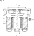
- FIG. 1 is a view illustrating a motor according to an embodiment.
- a motor 1 may include a shaft 100, a rotor 200, a stator 300, a housing 400, a busbar 500, a sensing unit 600, and a substrate 700.
- inside is referred to as a direction from the housing 400 toward the shaft 100 which is a center of the motor
- outside is referred to as a direction opposite to “inside” which is the direction from the shaft 100 toward the housing 400.
- the shaft 100 may be coupled to the rotor 200.
- the shaft 100 When an electromagnetic interaction occurs between the rotor 200 and the stator 300 due to the supply of a current, the rotor 200 rotates, and the shaft 100 rotates in conjunction with the rotor 200.
- the shaft 100 is rotatably supported by bearings 10.
- the shaft 100 may be connected to a vehicle's steering system, and power may be transmitted to the vehicle's steering system through the shaft 100.
- the rotor 200 rotates through the electrical interaction with the stator 300.
- the rotor 200 may be disposed inside the stator 300.
- the rotor 200 may include a rotor core 210 (see FIG. 2 ) and magnets 220 (see FIG. 2 ) disposed on the rotor core 210.
- the rotor 200 may be a surface permanent magnet (SPM) type rotor in which the magnets 220 are disposed on an outer circumferential surface of the rotor core 210.
- SPM surface permanent magnet
- the stator 300 is disposed outside the rotor 200.
- the stator 300 may include a stator core 300A, coils 300B, and an insulator 300C installed on the stator core 300A.
- the coil 300B may be wound around the insulator 300C.
- the insulator 300C is disposed between the coil 300B and the stator core 300A to serve to electrically insulate the stator core 300A from the coil 300B.
- the coil 300B induces an electrical interaction with the magnets 220 (see FIG. 2 ).
- the busbar 500 is disposed on the stator 300.
- the busbar 500 includes a busbar holder (not shown) formed of an insulating material and a plurality of terminals (not shown) coupled to the busbar holder.
- the busbar holder is formed of an insulating material to prevent the plurality of terminals from being connected to each other.
- the plurality of terminals serve to connect the coils 300B wound around the stator core 300A to apply a current to the coils.
- the sensing unit 600 may be coupled to the shaft 100.
- the sensing unit 600 includes a sensing plate (not shown) and a sensing magnet (not shown) disposed on the sensing plate.
- a sensor which detects a magnetic force of the sensing magnet (not shown), may be disposed on the substrate 700.
- the sensor may be a Hall integrated circuit (IC) and serve to detect a magnetic flux of the sensing magnet of the sensing unit 600 coupled to the shaft 100.
- the sensing unit 600 and the substrate 700 serve to detect a position of the rotor 200 by detecting the magnetic flux changed according to rotation.
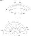
- FIG. 2 is an enlarged view illustrating a rotor core on which a first type magnet 220 and a groove are disposed.
- the stator core 300A may include a yoke 310 and a tooth 320.
- the tooth 320 may protrude from an inner circumferential surface of the yoke 310.
- the tooth 320 may include a plurality of teeth 320.
- the number of the teeth 320 may be variously changed according to the number of magnets 220.
- the stator core 300A may be formed by combining a plurality of divided cores each including the yoke 310 and the teeth 320.
- a cogging torque is generated as a wave having an amplitude and a frequency
- a cogging main degree is the number of vibration times of a cogging torque waveform per unit rotation (one rotation) of a motor.
- the cogging main degree may be determined by the number of the magnets 220 and the number of the teeth 320.
- the cogging torque may be reduced, but since the number of the magnets 220 and the number of the teeth 320 are fixed, the cogging main degree is also fixed.
- the cogging torque may be reduced using two methods.
- a shape of the rotor core 210 is changed (using a groove) to increase a cogging main degree so as to increase a frequency so that a magnitude of a cogging torque is reduced.
- a region in which a shape of the rotor core 210 is changed (using a groove) and a region in which the shape thereof is not changed are combined to induce interference between a cogging torque waveform with a normal phase and a cogging torque waveform with a reverse phase so as to reduce a magnitude of a cogging torque.
- the rotor core 210 includes a first region in which the magnet 220 is disposed.
- the first region is a region, on which the magnet 220 is seated or coupled thereto, of an outer surface of the rotor core 210.
- a first region A of the rotor core 210 may have a flat surface.
- a cross section of the rotor core 210 perpendicular to a longitudinal direction of the shaft 100 may have a polygonal shape.
- the first region A is an outer surface, which is disposed in an axial direction, of an outer surface of the rotor core 210, and when the rotor core 210 includes guide protrusions 212, the first region A may be a region between the guide protrusions 212 in a circumferential direction.
- the first region A may be a region between angled corners of the rotor core 210 in the circumferential direction.
- the first type magnet 220 may have a shape including an outer surface 221 having a curved shape and an inner surface 222 having a flat shape corresponding to the rotor core 210.
- the outer surface 221 of the magnet 220 is a surface facing the tooth 320 of the stator 300, and the inner surface 222 is a surface facing the rotor core 210 of the magnet 220.
- the outer surface 221 of the magnet 220 may have a shape of which a vicinity of a center protrudes further than both end portions thereof in the circumferential direction from the inner surface 222 of the magnet 220, and a curvature of the vicinity of the center of the curved-shaped outer surface 221 may be smaller than or equal to curvatures of the both end portions thereof.
- FIG. 3 is an enlarged view illustrating a rotor core on which a second type magnet 220 and a groove are disposed.
- a first region A of a rotor core 210 may have a curved surface.
- a cross section of the rotor core 210 perpendicular to the longitudinal direction of the shaft 100 may have a circular shape.
- the first region A is an outer surface, which is disposed in the axial direction, of an outer surface of the rotor core 210, and when the rotor core 210 includes guide protrusions 212, the first region A is a region between the guide protrusions 212 in the circumferential direction.
- the first region A may be an outer circumferential surface of the rotor core 210 corresponding to an inner surface 222 of the magnet 220 in the circumferential direction.
- the second type magnet 220 may have an outer surface 221 and the inner surface 222 each having a curved shape corresponding to the rotor core 210.
- a curvature radius of the inner surface 222 may be greater than a curvature radius of the outer surface 221.
- a curvature of the curved-shaped inner surface 222 may be constant along an outer circumferential surface of the first region A of the rotor core 210, and a curvature of a vicinity of a center of the curved-shaped outer surface 221 may be less than or equal to a curvature of each of both end portions thereof.
- two grooves 211 may be disposed in the first region A of the rotor core 210. Any one of two grooves 211 may be disposed at a position corresponding to one end region M1 of the magnet 220. The other one of two grooves 211 may be disposed at a position corresponding to the other end region M2 of the magnet 220. That is, one end region M1 and the other end region M2 of the magnet 220 may be both side surfaces of the magnet 220 or may be portions adjacent to the guide protrusions 212 when the rotor core 210 includes the guide protrusions 212. For example, in a radius direction from a center C of the rotor core 210, any one of two grooves 211 may be disposed to overlap one end region M1, and the other one of two grooves 211 may be disposed to overlap the other end region M2.
- a plurality of first regions A may be disposed.
- the number of the magnets 220 may be the same as the number of the first regions A.
- Two grooves 211 may be formed in at least two first regions A among the plurality of first regions A.
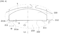
- FIG. 4 is an enlarged view illustrating the magnet 220 and the groove 211 illustrated in FIG. 2 .
- two grooves 211 may be symmetrically disposed with respect to a reference line L1 passing through a center C1 of a width, which is based on the circumferential direction, of the inner surface 222 of the magnet 220.
- the rotor core 210 may include a bottom surface 211a and a plurality of side surface 211b which constitute the groove 211.
- the bottom surface 211a is not in contact with the inner surface 222 of the magnet 220.
- the bottom surface 211a and the side surfaces 211b may be formed to extend in the axial direction.
- one side surface of the magnet 220 may be aligned with one of the plurality of side surfaces 211b constituting the groove 211, and in the groove 211 of the rotor core 220 corresponding to the other end region M2, the other side surface of the magnet 220 may be aligned with one of the plurality of side surfaces 211b constituting the groove 211.
- Two grooves 211 constitute air gaps between the magnet 220 and the rotor core 210 at both end regions M1 and M2 of the magnet 220.
- a magnitude of a magnetic flux may be reduced at each of both end regions M1 and M2 of the magnet 220 to reduce a cogging torque.
- the groove 211 is disposed in the outer surface of the rotor core 210 having an area which is relatively greater than an area of the tooth 320 of the stator 300, there advantages in that a design of the groove 211 is facilitated and dimensional accuracy of the groove 211 is high.
- FIG. 5 is a picture showing a magnitude of a magnetic flux around both end regions of magnets of a comparative example and a magnitude of a magnetic flux around both end regions M1 and M2 of the magnets 220 of an example.
- a left picture of FIG. 5 shows the magnitude of the magnetic flux of the comparative example which does not have a groove.
- a right picture of FIG. 5 shows the magnitude of the magnetic flux of the example having the groove 211.
- a portion G of FIG. 5 is a vicinity of both end regions M1 and M2 of the magnets 220. Based on the portion G of FIG. 5 , it may be seen that the magnitude of the magnetic flux of the example shown in the right picture of FIG. 5 is significantly reduced when compared to the magnitude of the magnetic flux of the comparative example shown in the left picture of FIG. 5 . This is due to the air gaps, which are formed by the grooves 211, between the magnets 220 and the rotor core 210.
- the cogging torque is greatly generated due to magnetic influence of both end regions M1 and M2 of the magnet 220 and the stator tooth 320, but when the magnitude of the magnetic flux of both end regions M1 and M2 of the magnets 220 is reduced as described, the magnetic influence is reduced, and accordingly, the cogging torque may be significantly reduced.
- FIG. 6 is a graph showing a first cogging torque waveform of the comparative example and a second cogging torque waveform of the example.
- a magnitude of a cogging torque of a first cogging torque waveform T1 of the comparative example, which does not have the groove 211 is 44 mNm, but a magnitude of a cogging torque of a second cogging torque waveform T2 of the example, in which the groove 211 is disposed, is 8 mNm which is reduced by 82% of the cogging torque measured in the comparative example.
- FIG. 7 is a view illustrating a rotor core 210 including a first rotor core 210A and a second rotor core 210B
- FIG. 8 is an enlarged view illustrating grooves 211 disposed in the first rotor core 210A illustrated in FIG. 7 .
- the rotor core 210 may include the first rotor core 210A and the second rotor core 210B.
- the first rotor core 210A and the second rotor core 210B are to reduce a magnitude of a cogging torque by inducing interference between a cogging torque waveform with a normal phase and a cogging torque waveform with a reverse phase.
- the first rotor core 210A and the second rotor core 210B may be coaxially stacked in the axial direction.
- the first rotor core 210A may include a first region A in which a part of a magnet 220 is disposed.
- the second rotor core 210B may include a second region B in which a part of the magnet 220 is disposed.
- Two grooves 211 may be disposed in the first region A. In the second region B, the grooves 211 may not be disposed in a region corresponding to two grooves 211 formed in the first region A in the axial direction.
- Two grooves 211 may be disposed at positions which do not correspond to both end regions M1 and M2 of the magnet 220. For example, in the radius direction based on the center C of the rotor core 210, two grooves 211 may be disposed not to overlap both end regions M1 and M2 of the magnet 220.
- Two grooves 211 may be symmetrically disposed with respect to a reference line L2 passing through a center C2 of a width of an inner surface 222 of the magnet 220 in the circumferential direction.
- FIG. 9 is a graph showing a third cogging torque waveform T3 generated due to the first rotor core 210A having the first region A, a fourth cogging torque waveform T4 generated due to the second rotor core 210B having the second region B, and a fifth cogging torque waveform generated due to cancellation between the third cogging torque waveform and the fourth cogging torque waveform.
- a phase of the third cogging torque waveform T3 and a phase of the fourth cogging torque waveform T4 are opposite to each other. Accordingly, the rotor core 210, in which the first rotor core 210A and the second rotor core 210B are stacked in the axial direction, generates the fifth cogging torque waveform T5 generated due to interference between the third cogging torque waveform T3 generated due to the first rotor core 210A and the fourth cogging torque waveform T4 generated due to the second rotor core 210B.
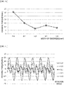
- FIG. 10 is a graph showing a magnitude of a cogging torque according to a width W of the groove 211
- FIG. 11 is a graph showing a cogging torque waveform according to the width W of the groove 211.
- a measured cogging torque is lower than a reference cogging torque.
- the reference cogging torque may have a reference value of a cogging torque desired in a product.
- the reference cogging torque may be 15 mNm.
- the width W of the groove 211 may be a width of the bottom surface 211a.
- an effect of reducing a measured cogging torque is higher than that in the section 1.
- the width W of the groove 211 is in the range of 7.5% to 10% of the length L of the inner surface 222 of the magnet 220 (hereinafter, referred to as a "section 2")
- an effect of reducing a measured cogging torque is higher than that in the section 1.
- the cogging torque is 10 mNm or less, and it is seen that an effect of reducing a cogging torque is the highest among those in the section 1 and the section 2.
- FIG. 12 is a graph showing a cogging torque according to a depth D of the groove 211
- FIG. 13 is a graph showing a cogging torque waveform according to the depth D of the groove 211.
- a measured cogging torque is lower than the reference cogging torque (for example, 20 mNm).
- the reference cogging torque for example, 20 mNm.
- the depth D of the groove 211 may be a length of the side surface 211b in the radius direction.
- section 4" In a section in which the depth of the groove 211 is in the range of 1.4% to 2.8% of the length L of the inner surface 222 of the magnet 220 (hereinafter, referred to as a "section 4"), it is seen that an effect of reducing a measured cogging torque is higher than that in the section 3.
- the length L of the inner surface 222 of the magnet 220 is 14 mm and the width W of the groove 211 is in the range of 0.2 mm to 0.39 mm, an effect of reducing a cogging torque is higher than that in the section 3.
- the cogging torque is 10 mNm or less, and it is seen that an effect of reducing a cogging torque is highest in comparison to those in the section 3 and the section 4.
- a reference point of the separation distance X may be a center of the width of the groove 211.
Landscapes
- Engineering & Computer Science (AREA)
- Power Engineering (AREA)
- Chemical & Material Sciences (AREA)
- Combustion & Propulsion (AREA)
- Transportation (AREA)
- Mechanical Engineering (AREA)
- Permanent Field Magnets Of Synchronous Machinery (AREA)
- Iron Core Of Rotating Electric Machines (AREA)
Abstract
Description
- The present invention relates to a motor.
- An electric power steering (EPS) system is an apparatus which secures turning stability of a vehicle and rapidly provides a restoring force so that a driver can safely drive the vehicle. The EPS system controls a vehicle's steering shaft to be driven by driving a motor using an electronic control unit (ECU) according to driving conditions detected by a vehicle speed sensor, a torque angle sensor, a torque sensor, and the like.
- The motor includes a stator and a rotor. The stator may include teeth constituting a plurality of slots, and the rotor may include a plurality of magnets facing the teeth. The adjacent teeth are disposed to be spaced apart from each other to constitute slot opens. In this case, a cogging torque may be generated due to a difference in magnetic permeability between the stator formed of a metal material and the slot open, which is an empty space, when the rotor rotates. The cogging torque affects sensitivity and output of steering, and accordingly, in order to reduce the cogging torque, grooves (notches) are formed in the tooth of the stator. However, when the grooves are formed in the tooth of the stator, due to errors in positions of the teeth, there is a problem in that deviation in position and shape between grooves occurs. In addition, since an area, in which the grooves are formed, of the tooth is limited, there is a problem of many limitations in determining the number, sizes, and shapes of the grooves.
- The present invention is directed to providing a motor of which a cogging torque is reducible.
- Objectives that have to be solved according to the embodiments are not limited to the above-described objectives, and other objectives which are not described above will be clearly understood by those skilled in the art from the following specification.
- One aspect of the present invention provides a motor including a rotor and a stator disposed to correspond to the rotor, wherein the rotor includes a rotor core and a magnet disposed on the rotor core, the rotor core includes a first region in which the magnet is disposed, the first region of the rotor core includes two grooves, one of the two grooves is disposed at a position corresponding to one end region of the magnet, and the other one of the two grooves is disposed at a position corresponding to the other end region of the magnet.
- The two grooves may overlap both end regions of the magnet in a radius direction from a center of the rotor core.
- Another aspect of the present invention provides a motor including a rotor, and a stator disposed to correspond to the rotor, wherein the rotor includes a rotor core and a magnet disposed on the rotor core, the rotor core includes a first rotor core and a second rotor core disposed on the first rotor core, the first rotor core includes a first region in which one part of the magnet is disposed, the second rotor core includes a second region in which another part of the magnet is disposed, one of the first region and the second region includes two grooves, and in the other one of the regions, a groove is not formed in a region corresponding to the two grooves in an axial direction.
- The magnet may include a plurality of magnets, the first region may include a plurality of first regions, and the two grooves may be formed in at least two first regions among the plurality of first regions.
- The number of the plurality of magnets may be the same as the number of the plurality of first regions.
- A cogging torque generated due to the stator and the magnet may be 10 mNm or less.
- The two grooves formed in the another of the regions may be formed so that each of the two grooves is formed at a position corresponding to one of both end regions of the magnet.
- The two grooves may not overlap both end regions of the magnet in a radius direction from a center of the rotor core.
- The two grooves may be symmetrically disposed with respect to a center of a width of an inner surface of the magnet in a circumferential direction.
- A distance between centers of the two grooves may be in the range of 10% to 30% of a length of the inner surface of the magnet.
- Still another aspect of the present invention provides a motor including a rotor and a stator disposed to correspond to the rotor, wherein the rotor includes a rotor core and a magnet disposed on the rotor core, the rotor core includes a first region in which the magnet is disposed, the first region of the rotor core includes a groove, and a cogging torque generated due to the stator and the magnet is 10 mNm or less.
- A width of the groove may be in the range of 6.5% to 13% of a length of an inner surface of the magnet.
- A depth of the groove may be in the range of 1% to 3.5% of the length of the inner surface of the magnet.
- The rotor core may include a bottom surface and a plurality of side surfaces which constitute the groove, and the bottom surface of the groove may not be in contact with the inner surface of the magnet.
- The bottom surface and the plurality of side surfaces may be formed to extend in an axial direction.
- According to an embodiment, an advantageous effect of significantly reducing a cogging torque is provided by reducing magnetic fluxes at both end portions of a magnet.
- According to an embodiment, since a cogging torque waveform due to a partial region, in which a groove is disposed, of a rotor and a cogging torque waveform due to the other region, in which a groove is not disposed, of the rotor cancel each other, an advantageous effect of reducing the cogging torque is provided.
-
-
FIG. 1 is a view illustrating a motor according to an embodiment. -
FIG. 2 is an enlarged view illustrating a rotor core on which a first type magnet and a groove are disposed. -
FIG. 3 is an enlarged view illustrating a rotor core on which a second type magnet and a groove are disposed. -
FIG. 4 is an enlarged view illustrating the magnet and the groove illustrated inFIG. 2 . -
FIG. 5 is a picture showing a magnitude of a magnetic flux around both end regions of magnets of a comparative example and a magnitude of a magnetic flux around both end regions of magnets of an example. -
FIG. 6 is a graph showing a first cogging torque waveform of the comparative example and a second cogging torque waveform of the example. -
FIG. 7 is a view illustrating a rotor core including a first rotor core and a second rotor core. -
FIG. 8 is an enlarged view illustrating a groove disposed in the rotor core illustrated inFIG. 7 . -
FIG. 9 is a graph showing a third cogging torque waveform generated due to a first region, a fourth cogging torque waveform generated due to a second region, and a fifth cogging torque waveform generated due to cancellation between the third cogging torque waveform and the fourth cogging torque waveform. -
FIG. 10 is a graph showing a cogging torque according to a width of the groove. -
FIG. 11 is a graph showing a cogging torque waveform according to the width of the groove. -
FIG. 12 is a graph showing a cogging torque according to a depth of the groove. -
FIG. 13 is a graph showing a cogging torque waveform according to the depth of the groove. - Hereinafter, exemplary embodiments of the present invention will be described with reference to the accompanying drawings in detail. Purposes, specific advantages, and novel features of the invention will be made clear from the exemplary embodiments and the following detailed description in connection with the accompanying drawings. In addition, in the description of the present invention, detailed descriptions of related well-known functions, which unnecessarily obscure the gist of the invention, will be omitted.
-
FIG. 1 is a view illustrating a motor according to an embodiment. - Referring to
FIG. 1 , a motor 1 according to the embodiment may include ashaft 100, arotor 200, astator 300, ahousing 400, abusbar 500, asensing unit 600, and asubstrate 700. Hereinafter, the term "inside" is referred to as a direction from thehousing 400 toward theshaft 100 which is a center of the motor, and the term "outside" is referred to as a direction opposite to "inside" which is the direction from theshaft 100 toward thehousing 400. - The
shaft 100 may be coupled to therotor 200. When an electromagnetic interaction occurs between therotor 200 and thestator 300 due to the supply of a current, therotor 200 rotates, and theshaft 100 rotates in conjunction with therotor 200. Theshaft 100 is rotatably supported bybearings 10. Theshaft 100 may be connected to a vehicle's steering system, and power may be transmitted to the vehicle's steering system through theshaft 100. - The
rotor 200 rotates through the electrical interaction with thestator 300. Therotor 200 may be disposed inside thestator 300. Therotor 200 may include a rotor core 210 (seeFIG. 2 ) and magnets 220 (seeFIG. 2 ) disposed on therotor core 210. In this case, therotor 200 may be a surface permanent magnet (SPM) type rotor in which themagnets 220 are disposed on an outer circumferential surface of therotor core 210. - The
stator 300 is disposed outside therotor 200. Thestator 300 may include astator core 300A,coils 300B, and aninsulator 300C installed on thestator core 300A. Thecoil 300B may be wound around theinsulator 300C. Theinsulator 300C is disposed between thecoil 300B and thestator core 300A to serve to electrically insulate thestator core 300A from thecoil 300B. Thecoil 300B induces an electrical interaction with the magnets 220 (seeFIG. 2 ). - The
busbar 500 is disposed on thestator 300. Thebusbar 500 includes a busbar holder (not shown) formed of an insulating material and a plurality of terminals (not shown) coupled to the busbar holder. In this case, the busbar holder is formed of an insulating material to prevent the plurality of terminals from being connected to each other. In addition, the plurality of terminals serve to connect thecoils 300B wound around thestator core 300A to apply a current to the coils. - The
sensing unit 600 may be coupled to theshaft 100. Thesensing unit 600 includes a sensing plate (not shown) and a sensing magnet (not shown) disposed on the sensing plate. - A sensor, which detects a magnetic force of the sensing magnet (not shown), may be disposed on the
substrate 700. In this case, the sensor may be a Hall integrated circuit (IC) and serve to detect a magnetic flux of the sensing magnet of thesensing unit 600 coupled to theshaft 100. Thesensing unit 600 and thesubstrate 700 serve to detect a position of therotor 200 by detecting the magnetic flux changed according to rotation. -
FIG. 2 is an enlarged view illustrating a rotor core on which afirst type magnet 220 and a groove are disposed. - Referring to
FIG. 2 , thestator core 300A may include ayoke 310 and atooth 320. Thetooth 320 may protrude from an inner circumferential surface of theyoke 310. Thetooth 320 may include a plurality ofteeth 320. The number of theteeth 320 may be variously changed according to the number ofmagnets 220. Thestator core 300A may be formed by combining a plurality of divided cores each including theyoke 310 and theteeth 320. - A cogging torque is generated as a wave having an amplitude and a frequency, and a cogging main degree is the number of vibration times of a cogging torque waveform per unit rotation (one rotation) of a motor. When the cogging main degree increases, since the number of the vibration times of the cogging torque waveform also increases, the cogging torque may be significantly reduced. The cogging main degree may be determined by the number of the
magnets 220 and the number of theteeth 320. When the cogging main degree increases, the cogging torque may be reduced, but since the number of themagnets 220 and the number of theteeth 320 are fixed, the cogging main degree is also fixed. - However, in the motor 1 according to the embodiment, the cogging torque may be reduced using two methods. In one method, a shape of the
rotor core 210 is changed (using a groove) to increase a cogging main degree so as to increase a frequency so that a magnitude of a cogging torque is reduced. In the other method, a region in which a shape of therotor core 210 is changed (using a groove) and a region in which the shape thereof is not changed are combined to induce interference between a cogging torque waveform with a normal phase and a cogging torque waveform with a reverse phase so as to reduce a magnitude of a cogging torque. - The
rotor core 210 includes a first region in which themagnet 220 is disposed. The first region is a region, on which themagnet 220 is seated or coupled thereto, of an outer surface of therotor core 210. - In
FIG. 2 , a first region A of therotor core 210 may have a flat surface. For example, a cross section of therotor core 210 perpendicular to a longitudinal direction of theshaft 100 may have a polygonal shape. The first region A is an outer surface, which is disposed in an axial direction, of an outer surface of therotor core 210, and when therotor core 210 includes guideprotrusions 212, the first region A may be a region between theguide protrusions 212 in a circumferential direction. When therotor core 210 does not include theguide protrusions 212, the first region A may be a region between angled corners of therotor core 210 in the circumferential direction. - The
first type magnet 220 may have a shape including anouter surface 221 having a curved shape and aninner surface 222 having a flat shape corresponding to therotor core 210. Theouter surface 221 of themagnet 220 is a surface facing thetooth 320 of thestator 300, and theinner surface 222 is a surface facing therotor core 210 of themagnet 220. Theouter surface 221 of themagnet 220 may have a shape of which a vicinity of a center protrudes further than both end portions thereof in the circumferential direction from theinner surface 222 of themagnet 220, and a curvature of the vicinity of the center of the curved-shapedouter surface 221 may be smaller than or equal to curvatures of the both end portions thereof. -
FIG. 3 is an enlarged view illustrating a rotor core on which asecond type magnet 220 and a groove are disposed. - In
FIG. 3 , a first region A of arotor core 210 may have a curved surface. For example, a cross section of therotor core 210 perpendicular to the longitudinal direction of theshaft 100 may have a circular shape. The first region A is an outer surface, which is disposed in the axial direction, of an outer surface of therotor core 210, and when therotor core 210 includes guideprotrusions 212, the first region A is a region between theguide protrusions 212 in the circumferential direction. When therotor core 210 does not include theguide protrusions 212 like portions P ofFIG. 3 , the first region A may be an outer circumferential surface of therotor core 210 corresponding to aninner surface 222 of themagnet 220 in the circumferential direction. - The
second type magnet 220 may have anouter surface 221 and theinner surface 222 each having a curved shape corresponding to therotor core 210. In the shape of themagnet 220, for example, a curvature radius of theinner surface 222 may be greater than a curvature radius of theouter surface 221. In this case, a curvature of the curved-shapedinner surface 222 may be constant along an outer circumferential surface of the first region A of therotor core 210, and a curvature of a vicinity of a center of the curved-shapedouter surface 221 may be less than or equal to a curvature of each of both end portions thereof. - Referring to
FIGS. 2 and3 , twogrooves 211 may be disposed in the first region A of therotor core 210. Any one of twogrooves 211 may be disposed at a position corresponding to one end region M1 of themagnet 220. The other one of twogrooves 211 may be disposed at a position corresponding to the other end region M2 of themagnet 220. That is, one end region M1 and the other end region M2 of themagnet 220 may be both side surfaces of themagnet 220 or may be portions adjacent to theguide protrusions 212 when therotor core 210 includes theguide protrusions 212. For example, in a radius direction from a center C of therotor core 210, any one of twogrooves 211 may be disposed to overlap one end region M1, and the other one of twogrooves 211 may be disposed to overlap the other end region M2. - A plurality of first regions A may be disposed. The number of the
magnets 220 may be the same as the number of the first regions A. Twogrooves 211 may be formed in at least two first regions A among the plurality of first regions A. -
FIG. 4 is an enlarged view illustrating themagnet 220 and thegroove 211 illustrated inFIG. 2 . - Referring to
FIG. 4 , twogrooves 211 may be symmetrically disposed with respect to a reference line L1 passing through a center C1 of a width, which is based on the circumferential direction, of theinner surface 222 of themagnet 220. - The
rotor core 210 may include abottom surface 211a and a plurality ofside surface 211b which constitute thegroove 211. In this case, thebottom surface 211a is not in contact with theinner surface 222 of themagnet 220. Thebottom surface 211a and the side surfaces 211b may be formed to extend in the axial direction. In addition, in thegroove 211 of therotor core 220 corresponding to one end region M1 of themagnet 220, one side surface of themagnet 220 may be aligned with one of the plurality of side surfaces 211b constituting thegroove 211, and in thegroove 211 of therotor core 220 corresponding to the other end region M2, the other side surface of themagnet 220 may be aligned with one of the plurality of side surfaces 211b constituting thegroove 211. - Two
grooves 211 constitute air gaps between themagnet 220 and therotor core 210 at both end regions M1 and M2 of themagnet 220. Thus, a magnitude of a magnetic flux may be reduced at each of both end regions M1 and M2 of themagnet 220 to reduce a cogging torque. In addition, since thegroove 211 is disposed in the outer surface of therotor core 210 having an area which is relatively greater than an area of thetooth 320 of thestator 300, there advantages in that a design of thegroove 211 is facilitated and dimensional accuracy of thegroove 211 is high. -
FIG. 5 is a picture showing a magnitude of a magnetic flux around both end regions of magnets of a comparative example and a magnitude of a magnetic flux around both end regions M1 and M2 of themagnets 220 of an example. - A left picture of
FIG. 5 shows the magnitude of the magnetic flux of the comparative example which does not have a groove. - A right picture of
FIG. 5 shows the magnitude of the magnetic flux of the example having thegroove 211. - A portion G of
FIG. 5 is a vicinity of both end regions M1 and M2 of themagnets 220. Based on the portion G ofFIG. 5 , it may be seen that the magnitude of the magnetic flux of the example shown in the right picture ofFIG. 5 is significantly reduced when compared to the magnitude of the magnetic flux of the comparative example shown in the left picture ofFIG. 5 . This is due to the air gaps, which are formed by thegrooves 211, between themagnets 220 and therotor core 210. - The cogging torque is greatly generated due to magnetic influence of both end regions M1 and M2 of the
magnet 220 and thestator tooth 320, but when the magnitude of the magnetic flux of both end regions M1 and M2 of themagnets 220 is reduced as described, the magnetic influence is reduced, and accordingly, the cogging torque may be significantly reduced. -
FIG. 6 is a graph showing a first cogging torque waveform of the comparative example and a second cogging torque waveform of the example. - Referring to
FIG. 6 , it may be seen that a magnitude of a cogging torque of a first cogging torque waveform T1 of the comparative example, which does not have thegroove 211, is 44 mNm, but a magnitude of a cogging torque of a second cogging torque waveform T2 of the example, in which thegroove 211 is disposed, is 8 mNm which is reduced by 82% of the cogging torque measured in the comparative example. -
FIG. 7 is a view illustrating arotor core 210 including afirst rotor core 210A and asecond rotor core 210B, andFIG. 8 is an enlargedview illustrating grooves 211 disposed in thefirst rotor core 210A illustrated inFIG. 7 . - Referring to
FIG. 7 , therotor core 210 may include thefirst rotor core 210A and thesecond rotor core 210B. Thefirst rotor core 210A and thesecond rotor core 210B are to reduce a magnitude of a cogging torque by inducing interference between a cogging torque waveform with a normal phase and a cogging torque waveform with a reverse phase. - The
first rotor core 210A and thesecond rotor core 210B may be coaxially stacked in the axial direction. - The
first rotor core 210A may include a first region A in which a part of amagnet 220 is disposed. - The
second rotor core 210B may include a second region B in which a part of themagnet 220 is disposed. - Two
grooves 211 may be disposed in the first region A. In the second region B, thegrooves 211 may not be disposed in a region corresponding to twogrooves 211 formed in the first region A in the axial direction. - Two
grooves 211 may be disposed at positions which do not correspond to both end regions M1 and M2 of themagnet 220. For example, in the radius direction based on the center C of therotor core 210, twogrooves 211 may be disposed not to overlap both end regions M1 and M2 of themagnet 220. - Two
grooves 211 may be symmetrically disposed with respect to a reference line L2 passing through a center C2 of a width of aninner surface 222 of themagnet 220 in the circumferential direction. -
FIG. 9 is a graph showing a third cogging torque waveform T3 generated due to thefirst rotor core 210A having the first region A, a fourth cogging torque waveform T4 generated due to thesecond rotor core 210B having the second region B, and a fifth cogging torque waveform generated due to cancellation between the third cogging torque waveform and the fourth cogging torque waveform. - A phase of the third cogging torque waveform T3 and a phase of the fourth cogging torque waveform T4 are opposite to each other. Accordingly, the
rotor core 210, in which thefirst rotor core 210A and thesecond rotor core 210B are stacked in the axial direction, generates the fifth cogging torque waveform T5 generated due to interference between the third cogging torque waveform T3 generated due to thefirst rotor core 210A and the fourth cogging torque waveform T4 generated due to thesecond rotor core 210B. - In the fifth cogging torque waveform T5, it may be seen that the cogging torque is significantly reduced.
-
FIG. 10 is a graph showing a magnitude of a cogging torque according to a width W of thegroove 211, andFIG. 11 is a graph showing a cogging torque waveform according to the width W of thegroove 211. - Referring to
FIGS. 4 ,10, and 11 , in a section in which the width W of thegroove 211 is in the range of 6.5% to 13% of a length L of theinner surface 222 of the magnet 220 (hereinafter, referred to as a "section 1"), a measured cogging torque is lower than a reference cogging torque. For example, when the length L of theinner surface 222 of themagnet 220 is 14 mm, and the width W of thegroove 211 is in the range of 0.9 to 1.8 mm, it may be seen that the measured cogging torque is lower than the reference cogging torque. The reference cogging torque may have a reference value of a cogging torque desired in a product. For example, the reference cogging torque may be 15 mNm. In this case, the width W of thegroove 211 may be a width of thebottom surface 211a. - In a section in which the width W of the
groove 211 is in the range of 7.5% to 10% of the length L of theinner surface 222 of the magnet 220 (hereinafter, referred to as a "section 2"), an effect of reducing a measured cogging torque is higher than that in the section 1. For example, when the length L of theinner surface 222 of themagnet 220 is 14 mm, and the width W of thegroove 211 is in the range of 1.05 mm to 1.4 mm, it is seen that an effect of reducing a measured cogging torque is higher than that in the section 1. - When the width W of the
groove 211 is 8.0% of the length L of theinner surface 222 of themagnet 220, for example, when the width W of thegroove 211 is 1.2 mm, the cogging torque is 10 mNm or less, and it is seen that an effect of reducing a cogging torque is the highest among those in the section 1 and thesection 2. -
FIG. 12 is a graph showing a cogging torque according to a depth D of thegroove 211, andFIG. 13 is a graph showing a cogging torque waveform according to the depth D of thegroove 211. - Referring to
FIGS. 4 ,12, and 13 , in a section in which the depth D of thegroove 211 is 1% to 3.5% of the length L of theinner surface 222 of the magnet 220 (hereinafter, referred to as a "section 3"), a measured cogging torque is lower than the reference cogging torque (for example, 20 mNm). For example, when the length L of theinner surface 222 of themagnet 220 is 14 mm and the depth of thegroove 211 is in the range of 0.15 to 0.5 mm, it may be seen that a measured cogging torque is lower than the reference cogging torque. In this case, the depth D of thegroove 211 may be a length of theside surface 211b in the radius direction. - In a section in which the depth of the
groove 211 is in the range of 1.4% to 2.8% of the length L of theinner surface 222 of the magnet 220 (hereinafter, referred to as a "section 4"), it is seen that an effect of reducing a measured cogging torque is higher than that in thesection 3. For example, when the length L of theinner surface 222 of themagnet 220 is 14 mm and the width W of thegroove 211 is in the range of 0.2 mm to 0.39 mm, an effect of reducing a cogging torque is higher than that in thesection 3. - When the depth of the
groove 211 is 2.1% of the length L of theinner surface 222 of themagnet 220, for example, when the depth of thegroove 211 is 0.3 mm, the cogging torque is 10 mNm or less, and it is seen that an effect of reducing a cogging torque is highest in comparison to those in thesection 3 and the section 4. - Meanwhile, when a separation distance X (see
FIG. 8 ) between twogrooves 211 disposed in the first region A is in the range of 10% to 30% of the length L of themagnet 220 of theinner surface 222, a cogging torque is significantly reduced. A reference point of the separation distance X (seeFIG. 8 ) may be a center of the width of thegroove 211. - Particularly, when the separation distance X between two
grooves 211 disposed in the first region A is 20% of the length L of theinner surface 222 of themagnet 220, an effect of reducing a cogging torque is highest. - As described above, the motor according to one exemplary embodiment of the present invention has been specifically described with reference to the accompanying drawings.
- The above description is only an example describing a technological scope of the present invention. Various changes, modifications, and replacements may be made by those skilled in the art without departing from the spirit and scope of the present invention. Therefore, the embodiments disclosed above and in the accompanying drawings should be considered in a descriptive sense only and not for limiting the technological scope. The technological scope of the present invention is not limited by the embodiments and the accompanying drawings. The scope of the present invention should be interpreted by the appended claims and encompass all equivalents falling within the scope of the appended claims.
Claims (15)
- A motor comprising:a rotor; anda stator disposed to correspond to the rotor,wherein the rotor includes a rotor core and a magnet disposed on the rotor core,the rotor core includes a first region in which the magnet is disposed,the first region of the rotor core includes two grooves,one of the two grooves is disposed at a position corresponding to one end region of the magnet, andthe other one of the two grooves is disposed at a position corresponding to the other end region of the magnet.
- The motor of claim 1, wherein the two grooves overlap both end regions of the magnet in a radius direction from a center of the rotor core.
- A motor comprising:a rotor; anda stator disposed to correspond to the rotor,wherein the rotor includes a rotor core and a magnet disposed on the rotor core,the rotor core includes a first rotor core and a second rotor core disposed on the first rotor core,the first rotor core includes a first region in which one part of the magnet is disposed,the second rotor core includes a second region in which another part of the magnet is disposed,one of the first region and the second region includes two grooves, andin the other one of the regions, a groove is not formed in a region corresponding to the two grooves in an axial direction.
- The motor of claim 1 or 3, wherein:the magnet includes a plurality of magnets;the first region includes a plurality of first regions; andthe two grooves are formed in at least two first regions among the plurality of first regions.
- The motor of claim 4, wherein the number of the plurality of magnets is the same as the number of the plurality of first regions.
- The motor of claim 1 or 3, wherein a cogging torque generated due to the stator and the magnet is 10 mNm or less.
- The motor of claim 3, wherein the two grooves formed in the another of the regions are formed so that each of the two grooves is formed at a position corresponding to one of both end regions of the magnet.
- The motor of claim 3, wherein the two grooves do not overlap both end regions of the magnet in a radius direction from a center of the rotor core.
- The motor of claim 8, wherein the two grooves are symmetrically disposed with respect to a center of a width of an inner surface of the magnet in a circumferential direction.
- The motor of claim 9, wherein a distance between centers of the two grooves is in the range of 10% to 30% of a length of the inner surface of the magnet.
- A motor comprising:a rotor; anda stator disposed to correspond to the rotor,wherein the rotor includes a rotor core and a magnet disposed on the rotor core,the rotor core includes a first region in which the magnet is disposed,the first region of the rotor core includes a groove, anda cogging torque generated due to the stator and the magnet is 10 mNm or less.
- The motor of claim 1, 10, or 11, wherein a width of the groove is in the range of 6.5% to 13% of a length of an inner surface of the magnet.
- The motor of claim 12, wherein a depth of the groove is in the range of 1% to 3.5% of the length of the inner surface of the magnet.
- The motor of claim 1, 3, or 11, wherein:the rotor core includes a bottom surface and a plurality of side surfaces which constitute the groove; andthe bottom surface of the groove is not in contact with the inner surface of the magnet.
- The motor of claim 14, wherein the bottom surface and the plurality of side surfaces are formed to extend in an axial direction.
Applications Claiming Priority (2)
| Application Number | Priority Date | Filing Date | Title |
|---|---|---|---|
| KR1020190090881A KR102875013B1 (en) | 2019-07-26 | 2019-07-26 | Motor |
| PCT/KR2020/009293 WO2021020772A1 (en) | 2019-07-26 | 2020-07-15 | Motor |
Publications (2)
| Publication Number | Publication Date |
|---|---|
| EP4007126A1 true EP4007126A1 (en) | 2022-06-01 |
| EP4007126A4 EP4007126A4 (en) | 2022-10-05 |
Family
ID=74228647
Family Applications (1)
| Application Number | Title | Priority Date | Filing Date |
|---|---|---|---|
| EP20846483.4A Pending EP4007126A4 (en) | 2019-07-26 | 2020-07-15 | ENGINE |
Country Status (6)
| Country | Link |
|---|---|
| US (1) | US12328035B2 (en) |
| EP (1) | EP4007126A4 (en) |
| JP (1) | JP7515566B2 (en) |
| KR (1) | KR102875013B1 (en) |
| CN (1) | CN114175474B (en) |
| WO (1) | WO2021020772A1 (en) |
Family Cites Families (21)
| Publication number | Priority date | Publication date | Assignee | Title |
|---|---|---|---|---|
| JP3855318B2 (en) | 1996-10-07 | 2006-12-06 | 松下電器産業株式会社 | Permanent magnet rotor and manufacturing method thereof |
| JPH1189141A (en) * | 1997-09-09 | 1999-03-30 | Mitsubishi Electric Corp | Permanent magnet rotor and manufacturing method thereof |
| JP4267309B2 (en) * | 2002-12-03 | 2009-05-27 | 株式会社ジェイテクト | Adhesive structure |
| JP2004260960A (en) * | 2003-02-27 | 2004-09-16 | Toyoda Mach Works Ltd | Electric motor |
| KR100905902B1 (en) * | 2007-04-25 | 2009-07-02 | 주식회사 캐프스 | Rotor structure of a XLC motor for automobile fuel pump |
| JP5611656B2 (en) * | 2009-05-29 | 2014-10-22 | アスモ株式会社 | Rotor and motor |
| US8242654B2 (en) | 2009-05-20 | 2012-08-14 | Asmo Co., Ltd. | Rotor and motor |
| JP5481160B2 (en) | 2009-10-30 | 2014-04-23 | ミネベア株式会社 | Motor and magnet |
| WO2012032591A1 (en) | 2010-09-06 | 2012-03-15 | 三菱電機株式会社 | Permanent magnet type rotating electrical machine and electrical power steering device using same |
| JP2014155372A (en) | 2013-02-12 | 2014-08-25 | Mitsubishi Electric Corp | Surface magnet rotor and manufacturing method therefor and permanent magnet dynamo-electric machine with surface magnet rotor and electric power steering device using permanent magnet dynamo-electric machine |
| JP2014197948A (en) | 2013-03-29 | 2014-10-16 | 株式会社富士通ゼネラル | Permanent magnet motor |
| JP5958502B2 (en) * | 2013-12-06 | 2016-08-02 | 株式会社デンソー | Rotor and rotating electric machine using the same |
| JP6565228B2 (en) | 2015-03-06 | 2019-08-28 | アイシン精機株式会社 | Electric motor |
| US11431214B2 (en) * | 2016-07-12 | 2022-08-30 | Lg Innotek Co., Ltd. | Rotor and motor comprising same |
| KR101908122B1 (en) * | 2016-08-17 | 2018-10-15 | 효성전기주식회사 | Rotor of spoke type motor |
| CN109643915B (en) * | 2016-09-05 | 2021-09-03 | Lg伊诺特有限公司 | Stator and motor including the same |
| DE202017100697U1 (en) * | 2017-02-09 | 2017-02-20 | Wittur Holding Gmbh | Electric motor with defined bonded permanent magnets |
| JPWO2019069547A1 (en) | 2017-10-06 | 2020-10-22 | 日本電産株式会社 | Rotor, motor and electric power steering device |
| JP2019083650A (en) * | 2017-10-31 | 2019-05-30 | 三菱電機株式会社 | Rotor, manufacturing method of rotor, and rotary electric machine |
| JP2018043026A (en) | 2017-11-16 | 2018-03-22 | 株式会社大一商会 | Game machine |
| KR102510261B1 (en) * | 2017-11-30 | 2023-03-15 | 엘지이노텍 주식회사 | Rotor and motor having the same |
-
2019
- 2019-07-26 KR KR1020190090881A patent/KR102875013B1/en active Active
-
2020
- 2020-07-15 JP JP2022505505A patent/JP7515566B2/en active Active
- 2020-07-15 EP EP20846483.4A patent/EP4007126A4/en active Pending
- 2020-07-15 WO PCT/KR2020/009293 patent/WO2021020772A1/en not_active Ceased
- 2020-07-15 CN CN202080054013.0A patent/CN114175474B/en active Active
- 2020-07-15 US US17/630,428 patent/US12328035B2/en active Active
Also Published As
| Publication number | Publication date |
|---|---|
| EP4007126A4 (en) | 2022-10-05 |
| KR20210012707A (en) | 2021-02-03 |
| US12328035B2 (en) | 2025-06-10 |
| JP2022542933A (en) | 2022-10-07 |
| KR102875013B1 (en) | 2025-10-22 |
| JP7515566B2 (en) | 2024-07-12 |
| WO2021020772A1 (en) | 2021-02-04 |
| US20220286003A1 (en) | 2022-09-08 |
| CN114175474B (en) | 2024-01-30 |
| CN114175474A (en) | 2022-03-11 |
Similar Documents
| Publication | Publication Date | Title |
|---|---|---|
| EP3509187B1 (en) | Stator, and motor comprising same | |
| EP2905876B1 (en) | Electric drive apparatus | |
| JP4296486B2 (en) | Variable reluctance resolver | |
| US11888355B2 (en) | Rotor and motor including same | |
| US10753771B2 (en) | Brushless resolver and rotation-angle detection device | |
| US11398759B2 (en) | Motor | |
| US11431214B2 (en) | Rotor and motor comprising same | |
| US12328035B2 (en) | Motor having rotor structure with grooves to reduce cogging torque | |
| US20210119497A1 (en) | Electric motor | |
| US12261480B2 (en) | Motor | |
| JP2006230125A (en) | Rotating electric machine | |
| KR102858700B1 (en) | Motor | |
| KR102566475B1 (en) | Motor | |
| EP4184757A1 (en) | Motor | |
| KR102491351B1 (en) | Motor | |
| KR20180068014A (en) | Rotor and Motor having the same | |
| KR20180007089A (en) | Rotor and Motor having the same | |
| KR20210138934A (en) | Motor | |
| KR20190033823A (en) | Motor | |
| JP2006300599A (en) | Rotation detector |
Legal Events
| Date | Code | Title | Description |
|---|---|---|---|
| STAA | Information on the status of an ep patent application or granted ep patent |
Free format text: STATUS: THE INTERNATIONAL PUBLICATION HAS BEEN MADE |
|
| PUAI | Public reference made under article 153(3) epc to a published international application that has entered the european phase |
Free format text: ORIGINAL CODE: 0009012 |
|
| STAA | Information on the status of an ep patent application or granted ep patent |
Free format text: STATUS: REQUEST FOR EXAMINATION WAS MADE |
|
| 17P | Request for examination filed |
Effective date: 20220221 |
|
| AK | Designated contracting states |
Kind code of ref document: A1 Designated state(s): AL AT BE BG CH CY CZ DE DK EE ES FI FR GB GR HR HU IE IS IT LI LT LU LV MC MK MT NL NO PL PT RO RS SE SI SK SM TR |
|
| REG | Reference to a national code |
Ref country code: DE Ref legal event code: R079 Free format text: PREVIOUS MAIN CLASS: H02K0001270000 Ipc: H02K0001278100 |
|
| A4 | Supplementary search report drawn up and despatched |
Effective date: 20220905 |
|
| RIC1 | Information provided on ipc code assigned before grant |
Ipc: H02K 29/03 20060101ALI20220830BHEP Ipc: B62D 5/04 20060101ALI20220830BHEP Ipc: H02K 21/14 20060101ALI20220830BHEP Ipc: H02K 1/2781 20220101AFI20220830BHEP |
|
| DAV | Request for validation of the european patent (deleted) | ||
| DAX | Request for extension of the european patent (deleted) | ||
| STAA | Information on the status of an ep patent application or granted ep patent |
Free format text: STATUS: EXAMINATION IS IN PROGRESS |
|
| 17Q | First examination report despatched |
Effective date: 20251020 |