EP3509187B1 - Stator, and motor comprising same - Google Patents
Stator, and motor comprising same Download PDFInfo
- Publication number
- EP3509187B1 EP3509187B1 EP17846952.4A EP17846952A EP3509187B1 EP 3509187 B1 EP3509187 B1 EP 3509187B1 EP 17846952 A EP17846952 A EP 17846952A EP 3509187 B1 EP3509187 B1 EP 3509187B1
- Authority
- EP
- European Patent Office
- Prior art keywords
- motor
- shoe
- groove
- grooves
- rotor
- Prior art date
- Legal status (The legal status is an assumption and is not a legal conclusion. Google has not performed a legal analysis and makes no representation as to the accuracy of the status listed.)
- Active
Links
- 230000008859 change Effects 0.000 description 11
- 230000010349 pulsation Effects 0.000 description 8
- 230000007423 decrease Effects 0.000 description 4
- 230000000694 effects Effects 0.000 description 4
- 230000004907 flux Effects 0.000 description 4
- 239000012212 insulator Substances 0.000 description 4
- 238000004804 winding Methods 0.000 description 4
- 230000003993 interaction Effects 0.000 description 3
- 230000004048 modification Effects 0.000 description 3
- 238000012986 modification Methods 0.000 description 3
- 230000035699 permeability Effects 0.000 description 3
- 229910000831 Steel Inorganic materials 0.000 description 2
- 230000004308 accommodation Effects 0.000 description 2
- 230000014509 gene expression Effects 0.000 description 2
- 238000000034 method Methods 0.000 description 2
- 239000010959 steel Substances 0.000 description 2
- 230000001419 dependent effect Effects 0.000 description 1
- 239000012530 fluid Substances 0.000 description 1
- 239000007769 metal material Substances 0.000 description 1
- 230000008569 process Effects 0.000 description 1
- 230000009467 reduction Effects 0.000 description 1
- 238000000926 separation method Methods 0.000 description 1
- 230000003068 static effect Effects 0.000 description 1
Images


Classifications
-
- H—ELECTRICITY
- H02—GENERATION; CONVERSION OR DISTRIBUTION OF ELECTRIC POWER
- H02K—DYNAMO-ELECTRIC MACHINES
- H02K1/00—Details of the magnetic circuit
- H02K1/06—Details of the magnetic circuit characterised by the shape, form or construction
- H02K1/12—Stationary parts of the magnetic circuit
- H02K1/14—Stator cores with salient poles
- H02K1/145—Stator cores with salient poles having an annular coil, e.g. of the claw-pole type
-
- H—ELECTRICITY
- H02—GENERATION; CONVERSION OR DISTRIBUTION OF ELECTRIC POWER
- H02K—DYNAMO-ELECTRIC MACHINES
- H02K21/00—Synchronous motors having permanent magnets; Synchronous generators having permanent magnets
- H02K21/12—Synchronous motors having permanent magnets; Synchronous generators having permanent magnets with stationary armatures and rotating magnets
- H02K21/14—Synchronous motors having permanent magnets; Synchronous generators having permanent magnets with stationary armatures and rotating magnets with magnets rotating within the armatures
- H02K21/16—Synchronous motors having permanent magnets; Synchronous generators having permanent magnets with stationary armatures and rotating magnets with magnets rotating within the armatures having annular armature cores with salient poles
-
- B—PERFORMING OPERATIONS; TRANSPORTING
- B62—LAND VEHICLES FOR TRAVELLING OTHERWISE THAN ON RAILS
- B62D—MOTOR VEHICLES; TRAILERS
- B62D5/00—Power-assisted or power-driven steering
- B62D5/04—Power-assisted or power-driven steering electrical, e.g. using an electric servo-motor connected to, or forming part of, the steering gear
-
- H—ELECTRICITY
- H02—GENERATION; CONVERSION OR DISTRIBUTION OF ELECTRIC POWER
- H02K—DYNAMO-ELECTRIC MACHINES
- H02K1/00—Details of the magnetic circuit
- H02K1/06—Details of the magnetic circuit characterised by the shape, form or construction
- H02K1/12—Stationary parts of the magnetic circuit
- H02K1/14—Stator cores with salient poles
- H02K1/146—Stator cores with salient poles consisting of a generally annular yoke with salient poles
-
- H—ELECTRICITY
- H02—GENERATION; CONVERSION OR DISTRIBUTION OF ELECTRIC POWER
- H02K—DYNAMO-ELECTRIC MACHINES
- H02K1/00—Details of the magnetic circuit
- H02K1/06—Details of the magnetic circuit characterised by the shape, form or construction
- H02K1/22—Rotating parts of the magnetic circuit
- H02K1/27—Rotor cores with permanent magnets
- H02K1/2706—Inner rotors
-
- H—ELECTRICITY
- H02—GENERATION; CONVERSION OR DISTRIBUTION OF ELECTRIC POWER
- H02K—DYNAMO-ELECTRIC MACHINES
- H02K29/00—Motors or generators having non-mechanical commutating devices, e.g. discharge tubes or semiconductor devices
- H02K29/03—Motors or generators having non-mechanical commutating devices, e.g. discharge tubes or semiconductor devices with a magnetic circuit specially adapted for avoiding torque ripples or self-starting problems
-
- H—ELECTRICITY
- H02—GENERATION; CONVERSION OR DISTRIBUTION OF ELECTRIC POWER
- H02K—DYNAMO-ELECTRIC MACHINES
- H02K3/00—Details of windings
- H02K3/46—Fastening of windings on the stator or rotor structure
- H02K3/52—Fastening salient pole windings or connections thereto
- H02K3/521—Fastening salient pole windings or connections thereto applicable to stators only
- H02K3/525—Annular coils, e.g. for cores of the claw-pole type
-
- H—ELECTRICITY
- H02—GENERATION; CONVERSION OR DISTRIBUTION OF ELECTRIC POWER
- H02K—DYNAMO-ELECTRIC MACHINES
- H02K7/00—Arrangements for handling mechanical energy structurally associated with dynamo-electric machines, e.g. structural association with mechanical driving motors or auxiliary dynamo-electric machines
- H02K7/003—Couplings; Details of shafts
-
- H—ELECTRICITY
- H02—GENERATION; CONVERSION OR DISTRIBUTION OF ELECTRIC POWER
- H02K—DYNAMO-ELECTRIC MACHINES
- H02K2213/00—Specific aspects, not otherwise provided for and not covered by codes H02K2201/00 - H02K2211/00
- H02K2213/03—Machines characterised by numerical values, ranges, mathematical expressions or similar information
Definitions
- Embodiments relate to a motor.
- a motor is a device which obtains torque by converting electrical energy into mechanical energy and is generally used for a vehicle, home appliances, industrial apparatuses, and the like.
- the motor may include a housing, a rotating shaft, a stator disposed on an inner circumferential surface of the housing, a rotor installed on an outer circumferential surface of the rotating shaft, and the like.
- the stator of the motor causes an electrical interaction with the rotor and induces the rotor to rotate.
- the motor may be used for a device for securing stability in steering of a vehicle.
- the motor may be used for an auxiliary steering system using separate power.
- the EPS system is an apparatus capable of allowing a driver to safely drive a vehicle by securing stability in turning of the vehicle and providing a quick restoring force.
- the EPS system controls driving of a steering shaft of the vehicle by driving the motor through an electronic control unit (ECU) according to driving conditions sensed by a vehicle speed sensor, a torque angle sensor, a torque sensor, and the like.
- ECU electronice control unit
- the motor includes a stator and a rotor.
- the stator may include a plurality of teeth which form a plurality of slots.
- the rotor may include a plurality of magnets arranged to face the teeth.
- adjacent teeth are arranged to be spaced apart and form a slot opening. That is, the slot opening may be formed to prevent a leakage of flux between the adjacent teeth.
- cogging torque may occur due to a difference in permeability between a stator core of a metal material and air in the slot opening which is an empty space. Since the cogging torque is a cause of noise and vibration, a reduction in cogging torque is more important to increase quality of the motor.
- the present invention is directed to providing a motor capable of improving quality by reducing cogging torque and torque ripple.
- One aspect of the present invention provides a motor according to claim 1. Further aspects of the present invention are provided by the motor according to the dependent claims 2-5.
- a motor according to the invention provides an advantageous effect of greatly reducing cogging torque by increasing a main cogging degree using grooves formed on teeth of a stator.
- the motor may increase motor quality by reducing cogging torque and torque ripple using grooves having a semicircular shape.
- the quality may be further improved, while maintaining motor performance, by limiting a position of the groove on the basis of a slot opening and limiting a radius of the groove on the basis of an air gap.
- ordinal numbers such as "second,” “first,” and the like may be used for describing a variety of components. However, the components are not limited by the terms. The terms are used only for distinguishing one component from another component. For example, without departing from the scope of the present invention, a second component may be referred to as a first component, and similarly, a first component may be referred to as a second component.
- the term "and/or" includes any and all combinations of one or a plurality of associated listed items.
- one component is “connected” or “joined” to another component, it should be understood that the one component may be directly connected or joined to the other component but another component may be present therebetween.
- one component is “directly connected” or “directly joined” to another component, it should be understood that no other component is present therebetween.
- any one component when any one component is described as being “on or under” another component, the two components may come into direct contact with each other or may come into indirect contact with each other with another component interposed therebetween.
- the term "on or under” may include not only an upward direction but also a downward direction on the basis of one component.
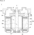
- FIG. 1 is a longitudinal cross-sectional view of a motor according to an embodiment.
- a motor 1 may include a housing 100, a bracket 200, a stator 300, a rotor 400, and a rotating shaft 500.
- the bracket 200 may be disposed to cover an open top of the housing 100.
- the housing 100 and the bracket 200 may form an outward form of the motor 1.
- the housing 100 may have a cylindrical shape with an opening on top.
- an accommodation space may be formed therein by a combination between the housing 100 and the bracket 200. Also, in the accommodation space, as shown in FIG. 1 , the stator 300, the rotor 400, the rotating shaft 500, and the like may be arranged.
- the housing 100 has a cylindrical shape such that the stator 300 may be disposed on an inner circumferential surface thereof to be supported.
- a pocket portion which accommodates a bearing 10 supporting a bottom of the rotating shaft, may be provided on a bottom of the housing 100.
- a pocket portion supporting a top of the rotating shaft 500 may be provided in the bracket 200 disposed above the housing 100.
- the bracket 200 may include a hole or a groove into which a connector, to which an external cable is connected, is inserted.
- the stator 300 may be supported by the inner circumferential surface of the housing 100. Also, the stator 300 is disposed outside the rotor 400.
- the stator 300 causes an electrical interaction with the rotor 400 and induces the rotor 400 to rotate.
- the rotor 400 is disposed inside the stator 300.
- the rotor 400 may include a rotor core and a magnet combined with the rotor core.
- the rotor 400 may have the following forms which are classified according to a method of combining the rotor core with the magnet.
- the rotor 400 may be embodied such that a magnet is combined with an outer circumferential surface of a rotor core.
- This type of rotor may include an additional can member 20 combined with the rotor core to prevent a separation of the magnet and to increase a combinational force therebetween. Otherwise, the magnet and the rotor core may be doubly injected to be integrally formed.
- the rotor 400 may be embodied such that a magnet is combined with an inside of a rotor core.
- This type of rotor may include a pocket, into which the magnet is inserted, in the rotor core.
- the rotor core may be formed by stacking a plurality of plates having a thin steel plate shape. Otherwise, the rotor core may be embodied to have one cylindrical shape so as to not form a skew angle, and the magnet may be attached to the rotor core so as to not form a skew angle. Meanwhile, the rotor core may be formed by stacking a plurality of pucks (unit core) which form a skew angle.
- the rotating shaft 500 may be combined with the rotor 400. When an electromagnetic interaction occurs between the stator 300 and the rotor 400 due to current supply, the rotor 400 rotates, and in connection therewith, the rotating shaft 500 rotates.
- the rotating shaft 500 may be connected to a steering shaft of a vehicle and may transfer power to the steering shaft.
- the rotating shaft 500 may be supported by the bearing 10 as shown in FIG. 1 .
- a sensing magnet assembly 600 is an apparatus which is combined with the rotating shaft 500 to be in connection with the rotor 400 so as to detect a position of the rotor 400.
- the sensing magnet assembly 600 may include a sensing magnet and a sensing plate.
- the sensing magnet and the sensing plate may be combined with each other to be coaxial.
- the sensing magnet may include a main magnet disposed in a circumferential direction to be adjacent to a hole forming an inner circumferential surface and a sub magnet formed on an edge.
- the main magnet may be disposed to be equal to a drive magnet which is inserted into the rotor 400 of the motor.
- the sub magnet is segmented more than the main magnet and includes a plurality of magnetic poles. Accordingly, it is possible to segment a magnet more, measure a rotation angle, and more easily drive the motor.
- the sensing plate may be formed as a metallic circular-plate-shape.
- the sensing magnet may be combined with a top surface of the sensing plate.
- the sensing plate may be combined with the rotating shaft 500.
- a hole, through which the rotating shaft 500 passes, is formed in the sensing plate.
- a sensor which senses a magnetic force of the sensing magnet may be disposed on a printed circuit board (PCB) 700.
- PCB printed circuit board
- the senor may be a hall integrated chip (IC).
- the sensor senses changes in the N pole and the S pole of the main magnet or the sub magnet and generates a sensing signal. Since at least three sensing signals for obtaining information on U, V, and W phases are necessary in the case of a three-phased brushless motor, at least three sensors may be arranged.
- the PCB 700 may be combined with a bottom surface of the bracket 200 and be disposed on the sensing magnet assembly 600 such that the sensor faces the sensing magnet.
- FIG. 2 is a view illustrating the stator and the rotor not forming part of the present invention
- FIG. 3 is a view illustrating a groove of a tooth not forming part of the present invention
- FIG. 4 is a table illustrating a main cogging degree increased by the motor according to the embodiment
- FIG. 5 is a view illustrating a width of the groove not forming part of the present invention
- FIG. 6 is a table illustrating a change in a cogging torque waveform according to the width of the groove
- FIG. 7 is a view illustrating an angle between a body and a shoe of the tooth not forming part of the present invention
- FIG. 1 is a view illustrating the stator and the rotor not forming part of the present invention
- FIG. 3 is a view illustrating a groove of a tooth not forming part of the present invention
- FIG. 4 is a table illustrating a main cogging degree increased by the motor according to the embodiment
- FIG. 5 is a view illustrating
- FIG. 8 is a graph illustrating a change in cogging torque according to an angle between the body and the shoe of the tooth
- FIG. 9 is a graph illustrating a change in cogging ripple according to an angle between the body and the shoe of the tooth
- FIG. 10 is a graph illustrating a change in a cogging torque wave according to an angle between the body and the shoe of the tooth.
- the stator 300 may include a stator core 310 and a coil 320. Also, in the stator 300, an insulator 330 may be disposed between the stator core 310 and the coil 320.
- the stator core 310 may be formed by stacking a plurality of plates having a thin steel plate shape. Also, the stator core 310 may be formed by combining and connecting a plurality of divided cores with or to one another.
- the stator core 310 may include a yoke 311, a plurality of teeth 312, and grooves 315 formed in the teeth 312.
- the groove 315 may be referred to as a notch.
- the teeth 312 protruding toward a center C may be arranged on the yoke 311.
- the yoke 311 may have an annular shape.
- the coil 320 is wound on the tooth 312.
- the plurality of teeth 312 may be arranged at certain intervals along an inner circumferential surface of the annular yoke. Although twelve teeth 312 are shown in FIG. 2 totally, the present invention is not limited thereto and a variety of modifications may be made according to the number of poles of magnets 420.
- the magnets 420 may be attached to an outer circumferential surface of a rotor core 410. An end of the tooth 312 is disposed to face the magnet 420.
- the rotor 400 may include the rotor core 410 and a plurality of such magnets 420 arranged on the rotor core 410.
- the tooth 312 may include a body 313 and a shoe 314.
- the body 313 may be referred to as a coil-wound portion.
- the shoe 314 may be referred to as a protrusion portion.
- the body 313 is a place where the coil 320 is wound.
- the shoe 314 is disposed on an end of the body 313.
- An end surface of the shoe 314 is disposed to face the magnet 420.
- a gap between the adjacent teeth 312 is formed as a space for winding the coil 320.
- the winding space S means a slot S.
- the shoes 314 of the adjacent teeth 312 are arranged to be separated from each other such that a slot opening O is formed.
- the slot opening O is an inlet of the winding space, into which a nozzle for winding the coil 320 is inserted.
- the end surface of the shoe 314 may include the grooves 315.
- the grooves 315 may be concavely formed on the end surface of the shoe 314. Although the grooves 315 have an angular shape, the present invention is not limited thereto.
- the groove 315 may be arranged along an axial direction of the stator core 310. In other words, the grooves 315 may be arranged lengthwise along a height direction (axial direction) of the stator core 310 from a top end to a bottom end of the stator core 310.
- Two such grooves 315 may be arranged. Referring to FIGS. 2 and 3 , the two grooves 315 may be arranged to be symmetrical to each other on the basis of a reference line L which passes a center of a width of the tooth 312 and the center C of the stator core 310.
- the grooves 315 increase a frequency of cogging torque waveforms per unit period by performing a function corresponding to that of the slot opening O, which causes a change in magnetic flux density, so as to greatly reduce the cogging torque.
- a main cogging degree corresponds to 24, which is a least common multiple of 8 which is the number of the magnets 420, and 12, which is the number of the slots.
- a main cogging degree corresponds to 18 which is a least common multiple of 8 which is the number of magnets and 9 which is the number of slots.
- the main cogging degree means a frequency of cogging torque waveforms per unit rotation (one rotation) of the motor.
- the frequency refers to the number of repeated cogging torque waveforms which form peaks.
- the number of slots corresponds to the number of the teeth 312.
- a width W1 of the groove 315 is set within a range of 90% to 110% of a width W2 of the slot opening O.
- the width W1 of the groove 315 means a distance from one side end to the other side end of an inlet of the groove 315 on the basis of a circumferential direction of the stator core 310.
- the width W2 of the slot opening O means a distance from one side end to the other side end of an inlet of the slot opening O on the basis of the circumferential direction of the stator core 310.
- an angle ⁇ formed by the body 313 and the shoe 314 of the tooth 312 may be 145° to 155°.
- an angle ⁇ formed by a side surface 313a of the body 313 and a side surface 314a of the shoe 314 connected to the side surface 313a of the body 313 may be 145° to 155°.
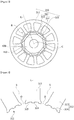
- FIG. 11 is a lateral cross-sectional view of the motor taken along a line A-A of FIG. 1 not forming part of the present invention
- FIG. 12 is a view illustrating an arrangement relationship between the stator core and the rotor of the motor according to the present invention
- FIG. 13 is a view illustrating the stator and the rotor in an area B1 of FIG. 12
- FIG. 14 is a view illustrating the tooth and the grooves of the motor according to the present invention
- FIG. 15 is a view illustrating comparison between torques of the motor according to the embodiment and a motor without grooves
- FIG. 16 is a view illustrating cogging torque and torque ripple according to a radius of the groove and a distance of an air gap formed in the motor according to the embodiment
- FIG. 17 is a view illustrating comparison between torques according to a radius of the groove and a distance of an air gap formed in the motor according to the embodiment
- FIG. 18 is a view illustrating cogging torque and torque ripple according to a position of a center C1 of the groove formed in the motor according to the embodiment
- FIG. 19 is a table illustrating performance of the motor according to the embodiment and a motor without grooves
- FIG. 20 is a view illustrating performance of the motor according to the embodiment and a motor without grooves at a room temperature
- FIG. 21 is a table illustrating performance of the motor according to the embodiment and a motor with a square notch formed therein
- FIG. 22 is a view illustrating performance of the motor according to the embodiment and a motor with a square notch formed therein.
- the stator 300 of the motor 1 may include the stator core 310, the coil 320, and the insulator 330.
- the stator core 310 may include the yoke 311, the plurality of teeth 312, and a plurality of the grooves 315 formed in the teeth 312.
- nine teeth 312 may be formed on the yoke 311.
- six magnets 420 may be arranged on the rotor core 410.
- each of the teeth 312 may include the body 313, on which the coil 320 is wound, and the shoe 314 formed to extend from the body 313.
- the yoke 311 may have a cylindrical shape.
- the plurality of teeth 312 may be arranged to protrude from the yoke 311 toward the center C.
- the teeth 312 may be arranged at certain intervals along an inner circumferential surface of the yoke 311 to protrude toward the center C.
- the plurality of teeth 312 may be arranged on the inner circumferential surface of the yoke 311 to be spaced at certain intervals apart.
- a space where the coil 320 is wound may be formed between one tooth 312 and another tooth 312 which are arranged to be adjacent to each other.
- the space means a slot S.
- an opening portion of the slot S may be formed.
- the opening portion means a slot opening O.
- the slot opening O means a space between an end point P of any one shoe 314 and an end point P of another shoe 314 adjacent thereto, and the slot opening O forms a certain angle ⁇ 1 on the basis of the center C of the rotating shaft 500.
- the angle ⁇ 1 may be four degrees on the basis of the center C of the rotating shaft 500.
- the angle ⁇ 1 refers to a width W2 of the slot opening O, and the width W2 means a distance between one side and the other side of the slot opening O.
- the coil 320 may be wound on the body 313.
- the insulator 330 may be disposed on the body 313.
- the insulator 330 insulates the body 313 from the coil 320.
- the body 313 may be disposed to protrude from the yoke 311 toward the center C.
- the shoe 314 may be formed to extend from an end part of the body 313. Also, the shoes 314 may be arranged to face the magnets 420.
- the plurality of grooves 315 may be arranged on the shoe 314.
- the groove 315 may have a semicircular shape.
- the shoes 314 may be arranged to face the magnets 420 while being spaced at a certain interval apart from the magnets 420. Accordingly, an air gap G may be formed between an inner surface of the shoe 314 and an outer surface of the magnet 420.
- the air gap G may mean a distance between the shoes 314 and the rotor 400.
- the air gap G may mean a distance between the shoes 314 and the magnets 420.
- an inside may mean a direction of being arranged to face the center C on the basis of the center C, and an outside may mean a direction opposite to the inside.
- the two grooves 315 may be on the shoe 314.
- the two grooves 315 may be arranged to be symmetrical to each other on the basis of a reference line L which passes a center of a width of the shoe 314 and the center C of the stator core 310.
- the grooves 315 perform a function of reducing a change in static magnetic energy (variation) by performing a function corresponding to the slot openings O which cause a change in magnetic flux density. Accordingly, the grooves 315 greatly reduce cogging torque by increasing a frequency of cogging torque waveforms per unit period.
- FIG. 15 is a view illustrating comparison between torques of the motor according to the embodiment and a motor without grooves.
- FIG. 15(a) illustrates pulsation of the motor without grooves
- FIG. 15(b) illustrates pulsation of the motor according to the embodiment.
- torque pulsation with respect to cogging torque and torque ripple may be calculated as a least common multiple of the number of poles (magnets) and the number of slots, in the case of a motor including 6 poles and 9 slots without the groove 315 as shown in FIG. 15(a) , 18, which is a least common multiple, corresponds to pulsation.
- the pulsation may mean the number of repeated waveforms which form peaks.
- the motor 1 may greatly reduce cogging torque.
- the grooves 315 may be formed toward the rotating shaft 500. As shown in FIG. 14 , the grooves 315 may be arranged lengthwise along a height direction (axial direction) from a top end to a bottom end of the stator core 310. Here, the grooves 315 may have a semicylindrical shape.
- a lateral cross section of the groove 315 may have a semicircular shape. Accordingly, the groove 315 may be formed to have a certain radius R on the basis of the center C1 of the groove 315.
- the semicircular groove 315 is advantageous for reducing cogging torque.
- the lateral direction may be perpendicular to the axial direction.
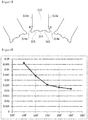
- FIG. 16 is a view illustrating cogging torque and torque ripple according to a radius of the groove and a distance of an air gap formed in the motor according to the embodiment.
- FIG. 16(a) is a view illustrating cogging torque according the radius of the groove and the distance of the air gap
- FIG. 16(b) is a view illustrating torque ripple according to the radius of the groove and the distance of the air gap.
- FIG. 17 is a view illustrating comparison between torques according to the radius of the groove and the distance of the air gap formed in the motor according to the embodiment.
- FIG. 17(a) is a view illustrating torque of the motor when the radius of the groove is different from the distance of the air gap
- FIG. 17(b) is a view illustrating torque of the motor when the radius of the groove is from the same as the distance of the air gap.
- a radius R of the groove 315 may be formed corresponding to a distance D of the air gap G.
- the distance D of the air gap G may be a distance between the shoe 314 and the center of the width of the magnet 420.
- the radius R of the groove 315 may be formed within a range of 0.9 to 1.1 in proportion to the distance D of the air gap G. That is, the radius R of the groove 315 may be determined within a range of ⁇ 10% of the distance D of the air gap G. Preferably, the radius R of the groove 315 may be formed to be equal to the distance D of the air gap G.
- cogging torque rapidly decreases when the radius R of the groove 315 is 0.45 mm and is located in a lowest position when the radius R of the groove 315 is 0.5 mm which is equal to the distance D of the air gap G. Then, an increase of the radius R of the groove 315 to 0.55 mm may be seen.
- the cogging torque has a lowest value when the radius R of the groove 315 is equal to the distance D of the air gap G.
- torque ripple maintains a low value when the radius R of the groove 315 is 0.45 mm to 0.55 mm. That is, it may be seen that the torque ripple rapidly decreases when the radius R of the groove 315 is 0.4 mm and is smoothly maintained when the radius R of the groove 315 is 0.45 mm to 0.55 mm.
- the torque ripple is located in a lowest position when the radius of the groove 315 is equal to the distance D of the air gap G. That is, the cogging ripple has a lowest value when the radius R of the groove 315 is 0.5 mm, which is equal to the distance D of the air gap G.
- the torque ripple maintains a low value when the radius R of the groove 315 is 0.9 to 1.1 in proportion to the distance D of the air gap G. That is, it may be seen that the torque ripple rapidly decreases when the radius R of the groove 315 is 0.8 in proportion to the distance D of the air gap and the torque ripple is smoothly maintained when the radius R of the groove 315 is 0.9 to 1.1 in proportion to the distance D of the air gap.
- the torque ripple has a lowest value when the radius R of the groove 315 is equal to the distance D of the air gap G.
- the torque of the motor 1 is improved 22% when the radius R of the groove 315 is equal to the distance D of the air gap G.
- cogging torque may be reduced by designing the radius R of the groove 315 to be equal to the distance D of the air gap G.
- the center C1 of the groove 315 may be disposed to be spaced at a certain angle ⁇ 2 in a circumferential direction apart from one side end point P of the shoe 314.
- the angle ⁇ 2 means a distance between the one side end point P of the shoe 314 and the center C1 of the groove 315.
- the angle ⁇ 2 refers to a position of the center C1 of the groove 315 in relation to the angle ⁇ 1 of the slot opening O.
- the angle ⁇ 2 may be referred to as a second angle ⁇ 2
- the angle ⁇ 1 may be referred to as a first angle ⁇ 1.
- the second angle ⁇ 2 may be formed within a range of 0.45 to 0.55 in proportion to the first angle ⁇ 1.
- the second angle ⁇ 2 may be formed within a range of 1.8 degrees to 2.2 degrees.
- the second angle ⁇ 2 may be formed to be 2.0 degrees.
- the center C1 of the groove 315 may be formed to be 0.45 to 0.55 from the one side end point P in proportion to the first angle ⁇ 1.
- the center C1 of the groove 315 may be formed to be 0.5 from the one side end point P of the shoe 314 in proportion to the first angle ⁇ 1.
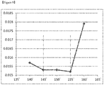
- FIG. 18 is a view illustrating cogging torque and torque ripple according to the position of the center C1 of the groove formed in the motor according to the embodiment.
- the number of the grooves 315 is 2
- the radius R of the groove 315 and the distance D of the air gap G are the same as 0.5 mm
- the first angle ⁇ 1 of the slot opening O is four degrees.
- cogging torque increases at an inflection point when a position of the center C1 of the groove 315 is located at an angle of 2.0 degrees from the one side end point P of the shoe 314.
- the motor 1 may perform effective performance.
- the position of the center C1 of the groove is located at 2.0 degrees from the one side end point P of the shoe 314, the cogging torque has a lowest value such that the motor 1 may perform optimum performance.
- a torque ripple value is maintained at about 100 mNm when a position of the center C1 of the groove 315 is located within a range of 1.8 degrees to 2.5 degrees from the one side end point P of the shoe 314.
- a range of the center C1 of the groove 315 located at 1.8 degrees to 2.2 degrees from the one side end point P of the shoe 314 may be checked as an optimum range.
- the cogging torque has a lowest value such that the motor 1 may perform optimum performance.
- the square notch has a difference between a length of one side and a length of a diagonal line. Particularly, based on a center of the square notch, a difference is present between a length of a side in a semidiameter direction (radial direction) and a diagonal line.
- the semicircular grooves 315 of the motor 1 are more effective in an aspect of cogging torque.
Description
- Embodiments relate to a motor.
- Documents
EP 2 378 627 A1 ,US 6 104 117 A ,JP 2010 172063 A JP 2009 189163 A WO 2011/149245 A2 ,DE 10 2015 210198 A1 ,WO 2008/050637 A1 ,KR 100 589 817 B1 US 2010/156226 A1 relate to a motor. - A motor is a device which obtains torque by converting electrical energy into mechanical energy and is generally used for a vehicle, home appliances, industrial apparatuses, and the like.
- The motor may include a housing, a rotating shaft, a stator disposed on an inner circumferential surface of the housing, a rotor installed on an outer circumferential surface of the rotating shaft, and the like. Here, the stator of the motor causes an electrical interaction with the rotor and induces the rotor to rotate.
- Particularly, the motor may be used for a device for securing stability in steering of a vehicle. For example, the motor may be used for an auxiliary steering system using separate power.
- Although auxiliary steering devices using fluid pressure were previously used, recently, electronic power steering systems (EPS) with low power loss and having high accuracy have been used.
- The EPS system is an apparatus capable of allowing a driver to safely drive a vehicle by securing stability in turning of the vehicle and providing a quick restoring force. The EPS system controls driving of a steering shaft of the vehicle by driving the motor through an electronic control unit (ECU) according to driving conditions sensed by a vehicle speed sensor, a torque angle sensor, a torque sensor, and the like.
- The motor includes a stator and a rotor.
- The stator may include a plurality of teeth which form a plurality of slots. The rotor may include a plurality of magnets arranged to face the teeth. Here, adjacent teeth are arranged to be spaced apart and form a slot opening. That is, the slot opening may be formed to prevent a leakage of flux between the adjacent teeth.
- Accordingly, although the flux moves through a tooth side having high permeability while the rotor rotates, torque pulsation may occur due to a difference in permeability in a slot opening area.
- Accordingly, while the rotor rotates, cogging torque may occur due to a difference in permeability between a stator core of a metal material and air in the slot opening which is an empty space. Since the cogging torque is a cause of noise and vibration, a reduction in cogging torque is more important to increase quality of the motor.
- The present invention is directed to providing a motor capable of improving quality by reducing cogging torque and torque ripple.
- Aspects of the embodiment are not limited to the above-stated aspect and other unstated aspects can be clearly understood by those skilled in the art from the following description.
- One aspect of the present invention provides a motor according to
claim 1. Further aspects of the present invention are provided by the motor according to the dependent claims 2-5. - A motor according to the invention provides an advantageous effect of greatly reducing cogging torque by increasing a main cogging degree using grooves formed on teeth of a stator.
- Also, the motor may increase motor quality by reducing cogging torque and torque ripple using grooves having a semicircular shape.
- Here, the quality may be further improved, while maintaining motor performance, by limiting a position of the groove on the basis of a slot opening and limiting a radius of the groove on the basis of an air gap.
- A variety of advantages and effects of the present invention are not limited to the above description and will be more easily understood in a process of describing detailed embodiments of the present invention. In the following detailed embodiments of motors not forming part of the present invention -namely with no grooves or square grooves arranged on the shoe- are described in order to outline the inventive effects of the invention. They are presented in comparison with embodiments according to the invention which comprise a shoe with semi-circular grooves.
-
-
FIG. 1 is a view of a motor according to an embodiment; -
FIG. 2 is a view illustrating a stator and a rotor not forming part of the present invention; -
FIG. 3 is a view illustrating a groove of a tooth not forming part of the present invention; -
FIG. 4 is a table illustrating a main cogging degree increased by the motor according to the embodiment; -
FIG. 5 is a view illustrating a width of the groove not forming part of the present invention; -
FIG. 6 is a table illustrating a change in a cogging torque waveform according to the width of the groove; -
FIG. 7 is a view illustrating an angle between a body and a shoe of the tooth not forming part of the present invention; -
FIG. 8 is a graph illustrating a change in cogging torque according to an angle between the body and the shoe of the tooth; -
FIG. 9 is a graph illustrating a change in cogging ripple according to an angle between the body and the shoe of the tooth; -
FIG. 10 is a graph illustrating a change in a cogging torque waveform according to an angle between the body and the shoe of the tooth; -
FIG. 11 is a lateral cross-sectional view of the motor taken along a line A-A ofFIG. 1 not forming part of the present invention; -
FIG. 12 is a view illustrating an arrangement relationship between a stator core and the rotor of the motor according to the present invention; -
FIG. 13 is a view illustrating the stator and the rotor in an area B1 ofFIG. 12 according to the present invention; -
FIG. 14 is a view illustrating the tooth and the grooves of the motor according to the present invention; -
FIG. 15 is a view illustrating comparison between torques of the motor according to the embodiment and a motor without grooves; -
FIG. 16 is a view illustrating cogging torque and torque ripple according to a radius of the groove and a distance of an air gap formed in the motor according to the embodiment; -
FIG. 17 is a view illustrating a comparison between torques according to a radius of the groove and a distance of an air gap formed in the motor according to the embodiment; -
FIG. 18 is a view illustrating cogging torque and torque ripple according to a position of a center C1 of the groove formed in the motor according to the embodiment; -
FIG. 19 is a table illustrating performance of the motor according to the embodiment and a motor without grooves; -
FIG. 20 is a view illustrating performance of the motor according to the embodiment and a motor without grooves at a room temperature; -
FIG. 21 is a table illustrating performance of the motor according to the embodiment and a motor with square notches formed therein; and -
FIG. 22 is a view illustrating performance of the motor according to the embodiment and a motor with square notches formed therein. - Although a variety of modifications and several embodiments of the present invention may be made, exemplary embodiments will be illustrated in the drawings and will be described. However, it should be understood that the present invention is not limited to the exemplary embodiments.
- The terms including ordinal numbers such as "second," "first," and the like may be used for describing a variety of components. However, the components are not limited by the terms. The terms are used only for distinguishing one component from another component. For example, without departing from the scope of the present invention, a second component may be referred to as a first component, and similarly, a first component may be referred to as a second component. The term "and/or" includes any and all combinations of one or a plurality of associated listed items.
- When it is stated that one component is "connected" or "joined" to another component, it should be understood that the one component may be directly connected or joined to the other component but another component may be present therebetween. On the other hand, when it is described that one component is "directly connected" or "directly joined" to another component, it should be understood that no other component is present therebetween.
- While the embodiments are described, when any one component is described as being "on or under" another component, the two components may come into direct contact with each other or may come into indirect contact with each other with another component interposed therebetween. Also, the term "on or under" may include not only an upward direction but also a downward direction on the basis of one component.
- Terms used herein are used merely for describing exemplary embodiments and are not intended to limit the present invention. Singular expressions, unless clearly defined otherwise in context, include plural expressions. Throughout the application, it should be understood that the terms "comprise," "have," and the like are used herein to specify the presence of stated features, numbers, steps, operations, elements, components or combinations thereof but do not preclude the presence or addition of one or more other features, numbers, steps, operations, elements, components, or combinations thereof.
- Unless defined otherwise, the terms used herein including technical or scientific terms have the same meanings as those which are generally understood by one of ordinary skill in the art. Terms such as those defined in commonly used dictionaries should be construed as having meanings equal to contextual meanings of related art and should not be interpreted in an idealized or excessively formal sense unless defined otherwise herein.
- Hereinafter, embodiments will be described in detail with reference to the attached drawings. Regardless of drawing signs, equal or corresponding elements will be referred to as like reference numerals and an overlapping description thereof will be omitted.
-
FIG. 1 is a longitudinal cross-sectional view of a motor according to an embodiment. - Referring to
FIG. 1 , amotor 1 according to the embodiment may include ahousing 100, abracket 200, astator 300, arotor 400, and arotating shaft 500. Here, thebracket 200 may be disposed to cover an open top of thehousing 100. - The
housing 100 and thebracket 200 may form an outward form of themotor 1. Here, thehousing 100 may have a cylindrical shape with an opening on top. - Accordingly, an accommodation space may be formed therein by a combination between the
housing 100 and thebracket 200. Also, in the accommodation space, as shown inFIG. 1 , thestator 300, therotor 400, therotating shaft 500, and the like may be arranged. - The
housing 100 has a cylindrical shape such that thestator 300 may be disposed on an inner circumferential surface thereof to be supported. A pocket portion, which accommodates abearing 10 supporting a bottom of the rotating shaft, may be provided on a bottom of thehousing 100. - Also, a pocket portion supporting a top of the
rotating shaft 500 may be provided in thebracket 200 disposed above thehousing 100. Also, thebracket 200 may include a hole or a groove into which a connector, to which an external cable is connected, is inserted. - The
stator 300 may be supported by the inner circumferential surface of thehousing 100. Also, thestator 300 is disposed outside therotor 400. - The
stator 300 causes an electrical interaction with therotor 400 and induces therotor 400 to rotate. - The
rotor 400 is disposed inside thestator 300. Therotor 400 may include a rotor core and a magnet combined with the rotor core. Therotor 400 may have the following forms which are classified according to a method of combining the rotor core with the magnet. - The
rotor 400 may be embodied such that a magnet is combined with an outer circumferential surface of a rotor core. This type of rotor may include anadditional can member 20 combined with the rotor core to prevent a separation of the magnet and to increase a combinational force therebetween. Otherwise, the magnet and the rotor core may be doubly injected to be integrally formed. - The
rotor 400 may be embodied such that a magnet is combined with an inside of a rotor core. This type of rotor may include a pocket, into which the magnet is inserted, in the rotor core. - Meanwhile, the rotor core may be formed by stacking a plurality of plates having a thin steel plate shape. Otherwise, the rotor core may be embodied to have one cylindrical shape so as to not form a skew angle, and the magnet may be attached to the rotor core so as to not form a skew angle. Meanwhile, the rotor core may be formed by stacking a plurality of pucks (unit core) which form a skew angle.
- The
rotating shaft 500 may be combined with therotor 400. When an electromagnetic interaction occurs between thestator 300 and therotor 400 due to current supply, therotor 400 rotates, and in connection therewith, therotating shaft 500 rotates. Therotating shaft 500 may be connected to a steering shaft of a vehicle and may transfer power to the steering shaft. Therotating shaft 500 may be supported by the bearing 10 as shown inFIG. 1 . - A
sensing magnet assembly 600 is an apparatus which is combined with therotating shaft 500 to be in connection with therotor 400 so as to detect a position of therotor 400. - The
sensing magnet assembly 600 may include a sensing magnet and a sensing plate. The sensing magnet and the sensing plate may be combined with each other to be coaxial. - The sensing magnet may include a main magnet disposed in a circumferential direction to be adjacent to a hole forming an inner circumferential surface and a sub magnet formed on an edge. The main magnet may be disposed to be equal to a drive magnet which is inserted into the
rotor 400 of the motor. The sub magnet is segmented more than the main magnet and includes a plurality of magnetic poles. Accordingly, it is possible to segment a magnet more, measure a rotation angle, and more easily drive the motor. - The sensing plate may be formed as a metallic circular-plate-shape. The sensing magnet may be combined with a top surface of the sensing plate. Also, the sensing plate may be combined with the
rotating shaft 500. Here, a hole, through which therotating shaft 500 passes, is formed in the sensing plate. - A sensor which senses a magnetic force of the sensing magnet may be disposed on a printed circuit board (PCB) 700.
- Here, the sensor may be a hall integrated chip (IC). The sensor senses changes in the N pole and the S pole of the main magnet or the sub magnet and generates a sensing signal. Since at least three sensing signals for obtaining information on U, V, and W phases are necessary in the case of a three-phased brushless motor, at least three sensors may be arranged.
- The
PCB 700 may be combined with a bottom surface of thebracket 200 and be disposed on thesensing magnet assembly 600 such that the sensor faces the sensing magnet. -
FIG. 2 is a view illustrating the stator and the rotor not forming part of the present invention,FIG. 3 is a view illustrating a groove of a tooth not forming part of the present invention,FIG. 4 is a table illustrating a main cogging degree increased by the motor according to the embodiment,FIG. 5 is a view illustrating a width of the groove not forming part of the present invention,FIG. 6 is a table illustrating a change in a cogging torque waveform according to the width of the groove,FIG. 7 is a view illustrating an angle between a body and a shoe of the tooth not forming part of the present invention,FIG. 8 is a graph illustrating a change in cogging torque according to an angle between the body and the shoe of the tooth,FIG. 9 is a graph illustrating a change in cogging ripple according to an angle between the body and the shoe of the tooth, andFIG. 10 is a graph illustrating a change in a cogging torque wave according to an angle between the body and the shoe of the tooth. - Referring to
FIGS. 2 to 10 , changes in cogging torque and torque ripple caused by the groove and shoe disposed on the tooth of the stator will be described. - Referring to
FIGS. 1 and2 , thestator 300 may include astator core 310 and acoil 320. Also, in thestator 300, aninsulator 330 may be disposed between thestator core 310 and thecoil 320. - The
stator core 310 may be formed by stacking a plurality of plates having a thin steel plate shape. Also, thestator core 310 may be formed by combining and connecting a plurality of divided cores with or to one another. - The
stator core 310 may include ayoke 311, a plurality ofteeth 312, andgrooves 315 formed in theteeth 312. Here, thegroove 315 may be referred to as a notch. - The
teeth 312 protruding toward a center C may be arranged on theyoke 311. Here, when viewed in an axial view (C), theyoke 311 may have an annular shape. Thecoil 320 is wound on thetooth 312. The plurality ofteeth 312 may be arranged at certain intervals along an inner circumferential surface of the annular yoke. Although twelveteeth 312 are shown inFIG. 2 totally, the present invention is not limited thereto and a variety of modifications may be made according to the number of poles ofmagnets 420. - The
magnets 420 may be attached to an outer circumferential surface of arotor core 410. An end of thetooth 312 is disposed to face themagnet 420. Here, therotor 400 may include therotor core 410 and a plurality ofsuch magnets 420 arranged on therotor core 410. - Referring to
FIG. 3 which illustrates an area B ofFIG. 2 , thetooth 312 may include abody 313 and ashoe 314. Here, thebody 313 may be referred to as a coil-wound portion. Also, theshoe 314 may be referred to as a protrusion portion. - The
body 313 is a place where thecoil 320 is wound. Theshoe 314 is disposed on an end of thebody 313. An end surface of theshoe 314 is disposed to face themagnet 420. A gap between theadjacent teeth 312 is formed as a space for winding thecoil 320. Here, the winding space S means a slot S. - The
shoes 314 of theadjacent teeth 312 are arranged to be separated from each other such that a slot opening O is formed. The slot opening O is an inlet of the winding space, into which a nozzle for winding thecoil 320 is inserted. - The end surface of the
shoe 314 may include thegrooves 315. Thegrooves 315 may be concavely formed on the end surface of theshoe 314. Although thegrooves 315 have an angular shape, the present invention is not limited thereto. Also, thegroove 315 may be arranged along an axial direction of thestator core 310. In other words, thegrooves 315 may be arranged lengthwise along a height direction (axial direction) of thestator core 310 from a top end to a bottom end of thestator core 310. - Two
such grooves 315 may be arranged. Referring toFIGS. 2 and 3 , the twogrooves 315 may be arranged to be symmetrical to each other on the basis of a reference line L which passes a center of a width of thetooth 312 and the center C of thestator core 310. Thegrooves 315 increase a frequency of cogging torque waveforms per unit period by performing a function corresponding to that of the slot opening O, which causes a change in magnetic flux density, so as to greatly reduce the cogging torque. - Referring to
FIG. 4 , in the case of a motor including eight poles and twelve slots without thegrooves 315, a main cogging degree corresponds to 24, which is a least common multiple of 8 which is the number of themagnets teeth 312. - In the case of a motor including 8 poles and 12 slots with two
grooves 315, since the number of slots is regarded as being increased from 12 to 36 by thegrooves 315, a main cogging degree increases three times from 24 to 72. Since increasing the main cogging degree three times using the twogrooves 315 as described above means increasing the frequency of cogging torque waveforms, cogging torque may be greatly reduced. - Referring to
FIGS. 5 and6 , a width W1 of thegroove 315 is set within a range of 90% to 110% of a width W2 of the slot opening O. Here, the width W1 of thegroove 315 means a distance from one side end to the other side end of an inlet of thegroove 315 on the basis of a circumferential direction of thestator core 310. Also, the width W2 of the slot opening O means a distance from one side end to the other side end of an inlet of the slot opening O on the basis of the circumferential direction of thestator core 310. - As shown in
FIG. 6(a) , when the width W1 of thegroove 315 deviates from the range of 90% to 110% of the width W2 of the slot opening O, a problem occurs in which a component of the stator, that is, a main cogging degree which is the same as the number of poles of themagnets 420, is included in a cogging torque waveform. - However, as shown in
FIG. 6(b) , it may be seen that when the width W1 of thegroove 315 is within the range of 90% to 110% of the width W2 of the slot opening O, only cogging torque waveforms corresponding to a main cogging degree of 72 are detected. - Referring to
FIG. 7 , an angle θ formed by thebody 313 and theshoe 314 of thetooth 312 may be 145° to 155°. In detail, an angle θ formed by aside surface 313a of thebody 313 and aside surface 314a of theshoe 314 connected to theside surface 313a of thebody 313 may be 145° to 155°. - Referring to
FIG. 8 , it may be seen that cogging torque is greatly reduced when the angle θ formed by thebody 313 and theshoe 314 is within a range from 145° to 155°. Simultaneously, referring toFIG. 9 , it may be seen that torque ripple is low when the angle θ formed by thebody 313 and theshoe 314 is within the range from 145° to 155° and greatly increases when the angle θ deviates from the range from 145° to 155°. Particularly, it may be seen that the torque ripple rapidly increases when the angle θ is greater than 155°. - Referring to
FIG. 10 , it may be checked that an amplitude of cogging torque waveforms is gradually reduced as the angle θ formed by aside surface 314a of theshoe 314 goes farther from 145° toward 155°. -
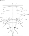
FIG. 11 is a lateral cross-sectional view of the motor taken along a line A-A ofFIG. 1 not forming part of the present invention,FIG. 12 is a view illustrating an arrangement relationship between the stator core and the rotor of the motor according to the present invention,FIG. 13 is a view illustrating the stator and the rotor in an area B1 ofFIG. 12 ,FIG. 14 is a view illustrating the tooth and the grooves of the motor according to the present invention,FIG. 15 is a view illustrating comparison between torques of the motor according to the embodiment and a motor without grooves,FIG. 16 is a view illustrating cogging torque and torque ripple according to a radius of the groove and a distance of an air gap formed in the motor according to the embodiment,FIG. 17 is a view illustrating comparison between torques according to a radius of the groove and a distance of an air gap formed in the motor according to the embodiment,FIG. 18 is a view illustrating cogging torque and torque ripple according to a position of a center C1 of the groove formed in the motor according to the embodiment,FIG. 19 is a table illustrating performance of the motor according to the embodiment and a motor without grooves,FIG. 20 is a view illustrating performance of the motor according to the embodiment and a motor without grooves at a room temperature,FIG. 21 is a table illustrating performance of the motor according to the embodiment and a motor with a square notch formed therein, andFIG. 22 is a view illustrating performance of the motor according to the embodiment and a motor with a square notch formed therein. - Referring to
FIGS. 11 to 22 , changes in torque, cogging torque and torque ripple caused by an air gap and grooves arranged on the tooth of the stator will be described. - Referring to
FIG. 11 , thestator 300 of themotor 1 may include thestator core 310, thecoil 320, and theinsulator 330. Also, thestator core 310 may include theyoke 311, the plurality ofteeth 312, and a plurality of thegrooves 315 formed in theteeth 312. Here, nineteeth 312 may be formed on theyoke 311. Also, corresponding to theteeth 312, sixmagnets 420 may be arranged on therotor core 410. - Also, each of the
teeth 312 may include thebody 313, on which thecoil 320 is wound, and theshoe 314 formed to extend from thebody 313. - The
yoke 311 may have a cylindrical shape. - The plurality of
teeth 312 may be arranged to protrude from theyoke 311 toward the center C. - As shown in
FIG. 12 , theteeth 312 may be arranged at certain intervals along an inner circumferential surface of theyoke 311 to protrude toward the center C. Here, the plurality ofteeth 312 may be arranged on the inner circumferential surface of theyoke 311 to be spaced at certain intervals apart. - Accordingly, a space where the
coil 320 is wound may be formed between onetooth 312 and anothertooth 312 which are arranged to be adjacent to each other. Here, the space means a slot S. - Also, as the
shoes 314 are arranged to be spaced apart, an opening portion of the slot S may be formed. Here, the opening portion means a slot opening O. - Accordingly, the slot opening O means a space between an end point P of any one
shoe 314 and an end point P of anothershoe 314 adjacent thereto, and the slot opening O forms a certain angle θ1 on the basis of the center C of therotating shaft 500. Here, the angle θ1 may be four degrees on the basis of the center C of therotating shaft 500. - As shown in
FIG. 13 , the angle θ1 refers to a width W2 of the slot opening O, and the width W2 means a distance between one side and the other side of the slot opening O. - The
coil 320 may be wound on thebody 313. Here, theinsulator 330 may be disposed on thebody 313. Theinsulator 330 insulates thebody 313 from thecoil 320. - Also, the
body 313 may be disposed to protrude from theyoke 311 toward the center C. - The
shoe 314 may be formed to extend from an end part of thebody 313. Also, theshoes 314 may be arranged to face themagnets 420. - Also, the plurality of
grooves 315 may be arranged on theshoe 314. When viewed in an axial view, thegroove 315 may have a semicircular shape. As shown inFIG. 12 , theshoes 314 may be arranged to face themagnets 420 while being spaced at a certain interval apart from themagnets 420. Accordingly, an air gap G may be formed between an inner surface of theshoe 314 and an outer surface of themagnet 420. - Here, the air gap G may mean a distance between the
shoes 314 and therotor 400. Preferably, the air gap G may mean a distance between theshoes 314 and themagnets 420. Here, an inside may mean a direction of being arranged to face the center C on the basis of the center C, and an outside may mean a direction opposite to the inside. - The two
grooves 315 may be on theshoe 314. Here, the twogrooves 315 may be arranged to be symmetrical to each other on the basis of a reference line L which passes a center of a width of theshoe 314 and the center C of thestator core 310. - The
grooves 315 perform a function of reducing a change in static magnetic energy (variation) by performing a function corresponding to the slot openings O which cause a change in magnetic flux density. Accordingly, thegrooves 315 greatly reduce cogging torque by increasing a frequency of cogging torque waveforms per unit period. -
FIG. 15 is a view illustrating comparison between torques of the motor according to the embodiment and a motor without grooves.FIG. 15(a) illustrates pulsation of the motor without grooves, andFIG. 15(b) illustrates pulsation of the motor according to the embodiment. - Referring to
FIG. 15 , since torque pulsation (repeated torque waveforms) with respect to cogging torque and torque ripple may be calculated as a least common multiple of the number of poles (magnets) and the number of slots, in the case of a motor including 6 poles and 9 slots without thegroove 315 as shown inFIG. 15(a) , 18, which is a least common multiple, corresponds to pulsation. Here, the pulsation may mean the number of repeated waveforms which form peaks. - Also, in the case of the
motor 1 according to the embodiment as shown inFIG. 15(b) , since the twogrooves 315 are formed on each of theshoes 314, 54, which is a least common multiple of 6 poles and 27 slots, may correspond to pulsation. - Accordingly, since a frequency of pulsation increases three times, the
motor 1 may greatly reduce cogging torque. - Meanwhile, the
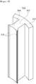
grooves 315 may be formed toward therotating shaft 500. As shown inFIG. 14 , thegrooves 315 may be arranged lengthwise along a height direction (axial direction) from a top end to a bottom end of thestator core 310. Here, thegrooves 315 may have a semicylindrical shape. - Accordingly, as shown in
FIGS. 12 and13 , a lateral cross section of thegroove 315 may have a semicircular shape. Accordingly, thegroove 315 may be formed to have a certain radius R on the basis of the center C1 of thegroove 315. - Accordingly, since a length of a magnetic path is equal in a lateral direction (a radial direction), the
semicircular groove 315 is advantageous for reducing cogging torque. Here, the lateral direction may be perpendicular to the axial direction. -
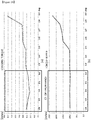
FIG. 16 is a view illustrating cogging torque and torque ripple according to a radius of the groove and a distance of an air gap formed in the motor according to the embodiment.FIG. 16(a) is a view illustrating cogging torque according the radius of the groove and the distance of the air gap, andFIG. 16(b) is a view illustrating torque ripple according to the radius of the groove and the distance of the air gap. -
FIG. 17 is a view illustrating comparison between torques according to the radius of the groove and the distance of the air gap formed in the motor according to the embodiment.FIG. 17(a) is a view illustrating torque of the motor when the radius of the groove is different from the distance of the air gap, andFIG. 17(b) is a view illustrating torque of the motor when the radius of the groove is from the same as the distance of the air gap. - Meanwhile, a radius R of the
groove 315 may be formed corresponding to a distance D of the air gap G. Here, the distance D of the air gap G may be a distance between theshoe 314 and the center of the width of themagnet 420. - Meanwhile, the radius R of the
groove 315 may be formed within a range of 0.9 to 1.1 in proportion to the distance D of the air gap G. That is, the radius R of thegroove 315 may be determined within a range of ±10% of the distance D of the air gap G. Preferably, the radius R of thegroove 315 may be formed to be equal to the distance D of the air gap G. - As shown in
FIG. 16(a) , cogging torque rapidly decreases when the radius R of thegroove 315 is 0.45 mm and is located in a lowest position when the radius R of thegroove 315 is 0.5 mm which is equal to the distance D of the air gap G. Then, an increase of the radius R of thegroove 315 to 0.55 mm may be seen. - That is, cogging torque rapidly decreases when the radius R of the
groove 315 is 0.9 in proportion to the distance D of the air gap G and is located in a lowest position when the radius R of thegroove 315 is equal to the distance D of the air gap G. Then, an increase of the radius R of thegroove 315 to 1.1 in proportion to the distance D of the air gap G may be seen. - Accordingly, the cogging torque has a lowest value when the radius R of the
groove 315 is equal to the distance D of the air gap G. - As shown in
FIG. 16(b) , it may be seen that torque ripple maintains a low value when the radius R of thegroove 315 is 0.45 mm to 0.55 mm. That is, it may be seen that the torque ripple rapidly decreases when the radius R of thegroove 315 is 0.4 mm and is smoothly maintained when the radius R of thegroove 315 is 0.45 mm to 0.55 mm. - Here, the torque ripple is located in a lowest position when the radius of the
groove 315 is equal to the distance D of the air gap G. That is, the cogging ripple has a lowest value when the radius R of thegroove 315 is 0.5 mm, which is equal to the distance D of the air gap G. - Accordingly, it may be seen that the torque ripple maintains a low value when the radius R of the
groove 315 is 0.9 to 1.1 in proportion to the distance D of the air gap G. That is, it may be seen that the torque ripple rapidly decreases when the radius R of thegroove 315 is 0.8 in proportion to the distance D of the air gap and the torque ripple is smoothly maintained when the radius R of thegroove 315 is 0.9 to 1.1 in proportion to the distance D of the air gap. - Accordingly, the torque ripple has a lowest value when the radius R of the
groove 315 is equal to the distance D of the air gap G. - Referring to
FIG. 17 , it may be seen that in comparison to a case in which the radius R of thegroove 315 is different from the distance D of the air gap G, the torque of themotor 1 is improved 22% when the radius R of thegroove 315 is equal to the distance D of the air gap G. - That is, cogging torque may be reduced by designing the radius R of the
groove 315 to be equal to the distance D of the air gap G. - Meanwhile, referring to
FIGS. 12 and13 , the center C1 of thegroove 315 may be disposed to be spaced at a certain angle θ2 in a circumferential direction apart from one side end point P of theshoe 314. Here, the angle θ2 means a distance between the one side end point P of theshoe 314 and the center C1 of thegroove 315. Additionally, the angle θ2 refers to a position of the center C1 of thegroove 315 in relation to the angle θ1 of the slot opening O. Here, for clarity, the angle θ2 may be referred to as a second angle θ2, and the angle θ1 may be referred to as a first angle θ1. - The second angle θ2 may be formed within a range of 0.45 to 0.55 in proportion to the first angle θ1. For example, when the first angle θ1 is 4 degrees, the second angle θ2 may be formed within a range of 1.8 degrees to 2.2 degrees. Preferably, the second angle θ2 may be formed to be 2.0 degrees.
- Accordingly, the center C1 of the
groove 315 may be formed to be 0.45 to 0.55 from the one side end point P in proportion to the first angle θ1. Preferably, the center C1 of thegroove 315 may be formed to be 0.5 from the one side end point P of theshoe 314 in proportion to the first angle θ1. -
FIG. 18 is a view illustrating cogging torque and torque ripple according to the position of the center C1 of the groove formed in the motor according to the embodiment. Here, the number of thegrooves 315 is 2, the radius R of thegroove 315 and the distance D of the air gap G are the same as 0.5 mm, and the first angle θ1 of the slot opening O is four degrees. - As shown in
FIG. 18(a) , cogging torque increases at an inflection point when a position of the center C1 of thegroove 315 is located at an angle of 2.0 degrees from the one side end point P of theshoe 314. - Accordingly, when the position of the center C1 of the
groove 315 is present within a range of 1.8 degrees to 2.2 degrees from the one side end point P of theshoe 314, themotor 1 may perform effective performance. Preferably, when the position of the center C1 of the groove is located at 2.0 degrees from the one side end point P of theshoe 314, the cogging torque has a lowest value such that themotor 1 may perform optimum performance. - As shown in
FIG. 18(b) , a torque ripple value is maintained at about 100 mNm when a position of the center C1 of thegroove 315 is located within a range of 1.8 degrees to 2.5 degrees from the one side end point P of theshoe 314. - Accordingly, in consideration of cogging torque and torque ripple of the
motor 1, a range of the center C1 of thegroove 315 located at 1.8 degrees to 2.2 degrees from the one side end point P of theshoe 314 may be checked as an optimum range. Particularly, when the position of the center C1 of thegroove 315 is located at 2.0 degrees from the one side end point P of theshoe 314, the cogging torque has a lowest value such that themotor 1 may perform optimum performance. - Hereinafter, referring to
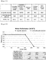
FIGS. 19 to 22 , performance of themotor 1 will be described. - Referring to
FIGS. 19 and 20 , it may be seen that in comparison to a motor without grooves, when thegrooves 315 are included as in themotor 1, cogging torque is reduced 79% and torque ripple is reduced 39.7%. Also, it may be seen that variation of values other than the cogging torque and the torque ripple are insignificant. - Accordingly, in the case of the
motor 1, in comparison with a motor without grooves, quality may be increased by reducing cogging torque and torque ripple while performance is indifferent from that of the motor without grooves. - Referring to
FIGS. 21 and 22 , it may be seen that in comparison to a motor with square notches, when the above-describedsemicircular grooves 315 are included as in themotor 1, cogging torque is reduced 67.4% and torque ripple is increased 2.5%. Also, it may be seen that variation of values other than the cogging torque and the torque ripple are insignificant. - Here, the square notch has a difference between a length of one side and a length of a diagonal line. Particularly, based on a center of the square notch, a difference is present between a length of a side in a semidiameter direction (radial direction) and a diagonal line.
- That is, since the square notches have a difference in directional lengths of a magnetic path, the
semicircular grooves 315 of themotor 1 are more effective in an aspect of cogging torque. - Accordingly, in the case of the
motor 1, in comparison with the motor with square notches, quality may be increased by reducing cogging torque while performance is indifferent from that of the motor without a groove. - Although an exemplary embodiment of the present invention has been described above, it should be understood by one of ordinary skill in the art that a variety of modifications and a variety of changes may be made without departing from the scope of the present invention which is defined in the following claims.
- 1: motor, 10: bearing, 100: housing, 200: bracket, 300: stator, 310: stator core, 311: yoke, 312: tooth, 313: body, 314: shoe, 315: groove, 320: coil, 400: rotor, 410: rotor core, 420: magnet, 500: rotating shaft, 600: sensing magnet assembly, 700: PCB.
Claims (5)
- A motor comprising:a rotating shaft (500);a rotor (400) comprising a rotor core (410) and magnets (420) arranged on an outer circumferential surface of the rotor core and a hole into which the rotating shaft (500) is inserted; anda stator (300) disposed outside the rotor (400),wherein the stator (300) comprises:a stator core (310) which comprises a plurality of teeth (312); anda coil (320) wound on each of the plurality of teeth (312),wherein each of the plurality of teeth (312) comprises a body (313), on which the coil (320) is wound, and a shoe (314) connected to the body (313),wherein the shoe (314) comprises a plurality of semicircular grooves (315), the grooves (315) being formed toward the rotating shaft (500), the grooves (315) being arranged lengthwise along an axial direction from a top end to a bottom end of the stator core (310), the grooves (315) having a semicylindrical shape, a lateral cross section of the grooves (315) having a semicircular shape,wherein the shoe (314) is arranged to face a magnet (420) of the rotor (400), an air gap (G) being formed between an inner surface of the shoe (314) and an outer surface of the magnet (420),wherein the number of the grooves (315) is two, and wherein the two grooves (315) are arranged to be symmetrical to each other on the basis of a reference line (L) which passes a center of a width of the shoe (314) based on a circumferential direction and a center of the stator core (310),characterized in thata center (C1) of a lateral cross section of the groove (315) is disposed to be spaced at a certain angle θ2 apart from one side end point (P) of the shoe (314) in a circumferential direction, on the basis of the center (C) of the rotating shaft,wherein the angle θ2 is 0.45 to 0.55 of an angle θ1 formed by a slot opening (O) being a space between an end point of the shoe (314) and an end point of another shoe (314) adjacent thereto, on the basis of the center (C) of the rotating shaft,wherein the radius (R) of the groove (315) is 0.9 to 1.1 of a distance (D) of the air gap (G) between the inner surface of the shoe (314) and the outer surface of the magnet (420) at the center of the width of the magnet (420).
- The motor of claim 1, wherein the angle θ2 is 0.5 of the angle θ1.
- The motor of any one of claims 1 to 2, wherein the radius (R) of the groove (315) is equal to the distance (D) of the air gap (G) between the inner surface of the shoe (314) and the outer surface of the magnet (420) at the center of the width of the magnet (420).
- The motor of any one of claims 1 to 3, wherein an angle formed by a side surface (313a) of the body (313) and a side surface (314a) of the shoe (314), which is connected to the side surface (313a) of the body (313), is 145° to 155°.
- The motor of claim 1, wherein nine teeth (312) are formed on a yoke (311) of the stator core (310), and
wherein six magnets (420) are arranged on the rotor core (410) of the rotor (400).
Applications Claiming Priority (3)
| Application Number | Priority Date | Filing Date | Title |
|---|---|---|---|
| KR1020160114086A KR20180027021A (en) | 2016-09-05 | 2016-09-05 | Stator and motor having the same |
| KR1020170013935A KR20180089173A (en) | 2017-01-31 | 2017-01-31 | Motor |
| PCT/KR2017/009410 WO2018044027A1 (en) | 2016-09-05 | 2017-08-29 | Stator, and motor comprising same |
Publications (3)
| Publication Number | Publication Date |
|---|---|
| EP3509187A1 EP3509187A1 (en) | 2019-07-10 |
| EP3509187A4 EP3509187A4 (en) | 2019-09-11 |
| EP3509187B1 true EP3509187B1 (en) | 2021-12-15 |
Family
ID=61301054
Family Applications (1)
| Application Number | Title | Priority Date | Filing Date |
|---|---|---|---|
| EP17846952.4A Active EP3509187B1 (en) | 2016-09-05 | 2017-08-29 | Stator, and motor comprising same |
Country Status (5)
| Country | Link |
|---|---|
| US (1) | US20190199147A1 (en) |
| EP (1) | EP3509187B1 (en) |
| JP (1) | JP6982612B2 (en) |
| CN (1) | CN109643915B (en) |
| WO (1) | WO2018044027A1 (en) |
Families Citing this family (12)
| Publication number | Priority date | Publication date | Assignee | Title |
|---|---|---|---|---|
| CA3024781A1 (en) * | 2017-11-21 | 2019-05-21 | Mcmaster University | Multi-teeth switched reluctance motor with short flux path |
| KR102633273B1 (en) * | 2018-08-30 | 2024-02-05 | 엘지이노텍 주식회사 | Motor |
| KR20200086087A (en) * | 2019-01-08 | 2020-07-16 | 엘지이노텍 주식회사 | Motor |
| KR20210012707A (en) * | 2019-07-26 | 2021-02-03 | 엘지이노텍 주식회사 | Motor |
| TWI723493B (en) | 2019-08-14 | 2021-04-01 | 財團法人工業技術研究院 | Combined motor stator |
| DE102019122271A1 (en) * | 2019-08-20 | 2021-02-25 | Schaeffler Technologies AG & Co. KG | Electric motor with a recess in a radial pole edge area |
| KR20210043079A (en) * | 2019-10-11 | 2021-04-21 | 현대자동차주식회사 | Motor having asymmetry rotor core |
| EP3863152A1 (en) | 2020-02-07 | 2021-08-11 | Sicor S.p.A. | Stator for an electric motor or generator and motor or generator comprising such a stator |
| CN112366845A (en) * | 2020-12-17 | 2021-02-12 | 哈尔滨理工大学 | High-efficiency back-wound winding tooth-groove-free permanent magnet synchronous motor |
| FR3128073A1 (en) | 2021-10-12 | 2023-04-14 | Nidec Psa Emotors | Stator of rotating electric machine |
| CN114614611B (en) * | 2021-12-14 | 2023-09-08 | 苏州长风航空电子有限公司 | Angular displacement sensor sensitive assembly |
| JP7310971B1 (en) * | 2022-04-28 | 2023-07-19 | 株式会社明電舎 | stator and rotating machine |
Citations (3)
| Publication number | Priority date | Publication date | Assignee | Title |
|---|---|---|---|---|
| EP0709947A2 (en) * | 1994-10-28 | 1996-05-01 | Hewlett-Packard Company | Balancing of radial reluctance forces in a DC motor |
| US20120025665A1 (en) * | 2010-07-27 | 2012-02-02 | Minebea Co., Ltd. | Single-phase brushless motor |
| EP2378627B9 (en) * | 2010-04-13 | 2014-02-26 | ebm-papst Mulfingen GmbH & Co. KG | Electric motor |
Family Cites Families (25)
| Publication number | Priority date | Publication date | Assignee | Title |
|---|---|---|---|---|
| JPH08308198A (en) * | 1995-05-08 | 1996-11-22 | Nippon Seiko Kk | Brushless motor |
| JPH1042531A (en) * | 1996-05-24 | 1998-02-13 | Matsushita Electric Ind Co Ltd | Motor |
| WO2001057987A1 (en) * | 2000-02-01 | 2001-08-09 | Pacsci Motion Control, Inc. | Brushless dc motor having reduced cogging torque |
| JP3691345B2 (en) * | 2000-05-25 | 2005-09-07 | 三菱電機株式会社 | Permanent magnet type motor |
| JP2003018773A (en) * | 2001-06-28 | 2003-01-17 | Sankyo Seiki Mfg Co Ltd | Motor with core |
| EP1492216A4 (en) * | 2002-03-29 | 2011-03-23 | Panasonic Corp | Motor |
| JP4244299B2 (en) * | 2003-03-12 | 2009-03-25 | 三菱電機株式会社 | Permanent magnet type motor for electric power steering system |
| JP4566590B2 (en) * | 2004-03-19 | 2010-10-20 | 三菱電機株式会社 | Permanent magnet type motor |
| JPWO2008050637A1 (en) * | 2006-10-25 | 2010-02-25 | 株式会社ミツバ | Brushless motor |
| CN101330231A (en) * | 2007-06-19 | 2008-12-24 | 上海海立(集团)股份有限公司 | Permanent magnet motor stator and rotor for compressor |
| JP2009189163A (en) * | 2008-02-06 | 2009-08-20 | Nippon Densan Corp | Electric motor |
| US20090236920A1 (en) * | 2008-03-18 | 2009-09-24 | Delphi Technologies Inc. | Systems and methods involving opitmized motors |
| US20100156226A1 (en) * | 2008-12-19 | 2010-06-24 | Gm Global Technology Operations, Inc. | Brush type motor |
| JP2010172063A (en) * | 2009-01-20 | 2010-08-05 | Mitsuba Corp | Outer rotor brushless motor |
| WO2011149245A2 (en) * | 2010-05-24 | 2011-12-01 | 학교법인 두원학원 | Structure of electric compressor motor |
| JP5073805B2 (en) * | 2010-11-22 | 2012-11-14 | 三菱電機株式会社 | Permanent magnet type motor and permanent magnet type linear motor |
| CN103683562B (en) * | 2012-09-17 | 2016-08-31 | 美的集团股份有限公司 | A kind of direct current generator, frequency-changeable compressor and full DC frequency converting air-conditioner off-premises station |
| US10186916B2 (en) * | 2012-12-28 | 2019-01-22 | Top Co., Ltd | Rotary machine and electric vehicle |
| JP2015070663A (en) * | 2013-09-27 | 2015-04-13 | アスモ株式会社 | Motor |
| CN103746473A (en) * | 2014-01-13 | 2014-04-23 | 广东美芝精密制造有限公司 | Motor for compressor and compressor with motor |
| KR20150104240A (en) * | 2014-03-04 | 2015-09-15 | 주식회사 시스웍 | Electromotion grinder using remote control BLDC motor |
| CN103956838A (en) * | 2014-05-21 | 2014-07-30 | 黄石东贝电器股份有限公司 | Stator used in brushless direct current motor and used for reducing fundamental wave cogging torque |
| US20160149444A1 (en) * | 2014-11-24 | 2016-05-26 | Hyundai Motor Company | Stator of interior permanent magnet synchronous motor |
| CN204465165U (en) * | 2015-04-02 | 2015-07-08 | 台州宝达机电有限公司 | The stator punching of magneto |
| JP2018061392A (en) * | 2016-10-07 | 2018-04-12 | 株式会社デンソー | Armature and rotary electric machine |
-
2017
- 2017-08-29 EP EP17846952.4A patent/EP3509187B1/en active Active
- 2017-08-29 JP JP2019511691A patent/JP6982612B2/en active Active
- 2017-08-29 US US16/329,641 patent/US20190199147A1/en not_active Abandoned
- 2017-08-29 CN CN201780053434.XA patent/CN109643915B/en active Active
- 2017-08-29 WO PCT/KR2017/009410 patent/WO2018044027A1/en active Application Filing
Patent Citations (3)
| Publication number | Priority date | Publication date | Assignee | Title |
|---|---|---|---|---|
| EP0709947A2 (en) * | 1994-10-28 | 1996-05-01 | Hewlett-Packard Company | Balancing of radial reluctance forces in a DC motor |
| EP2378627B9 (en) * | 2010-04-13 | 2014-02-26 | ebm-papst Mulfingen GmbH & Co. KG | Electric motor |
| US20120025665A1 (en) * | 2010-07-27 | 2012-02-02 | Minebea Co., Ltd. | Single-phase brushless motor |
Also Published As
| Publication number | Publication date |
|---|---|
| CN109643915A (en) | 2019-04-16 |
| US20190199147A1 (en) | 2019-06-27 |
| EP3509187A1 (en) | 2019-07-10 |
| WO2018044027A1 (en) | 2018-03-08 |
| JP6982612B2 (en) | 2021-12-17 |
| JP2019527016A (en) | 2019-09-19 |
| EP3509187A4 (en) | 2019-09-11 |
| CN109643915B (en) | 2021-09-03 |
Similar Documents
| Publication | Publication Date | Title |
|---|---|---|
| EP3509187B1 (en) | Stator, and motor comprising same | |
| US11876403B2 (en) | Stator and motor including same | |
| EP3550701A1 (en) | Cover assembly, motor and electric steering device including same | |
| KR20230127182A (en) | Motor | |
| KR20180089173A (en) | Motor | |
| CN111670529B (en) | Rotor and motor including the same | |
| KR20190023243A (en) | Stator and motor having the same | |
| KR20180027021A (en) | Stator and motor having the same | |
| JP2022516269A (en) | motor | |
| US20220286003A1 (en) | Motor | |
| KR20200021372A (en) | Motor | |
| KR20190063361A (en) | Motor | |
| KR20180068014A (en) | Rotor and Motor having the same | |
| US11398759B2 (en) | Motor | |
| KR20200064530A (en) | Motor | |
| KR20180007089A (en) | Rotor and Motor having the same |
Legal Events
| Date | Code | Title | Description |
|---|---|---|---|
| STAA | Information on the status of an ep patent application or granted ep patent |
Free format text: STATUS: THE INTERNATIONAL PUBLICATION HAS BEEN MADE |
|
| PUAI | Public reference made under article 153(3) epc to a published international application that has entered the european phase |
Free format text: ORIGINAL CODE: 0009012 |
|
| STAA | Information on the status of an ep patent application or granted ep patent |
Free format text: STATUS: REQUEST FOR EXAMINATION WAS MADE |
|
| 17P | Request for examination filed |
Effective date: 20190220 |
|
| AK | Designated contracting states |
Kind code of ref document: A1 Designated state(s): AL AT BE BG CH CY CZ DE DK EE ES FI FR GB GR HR HU IE IS IT LI LT LU LV MC MK MT NL NO PL PT RO RS SE SI SK SM TR |
|
| AX | Request for extension of the european patent |
Extension state: BA ME |
|
| A4 | Supplementary search report drawn up and despatched |
Effective date: 20190814 |
|
| RIC1 | Information provided on ipc code assigned before grant |
Ipc: H02K 21/16 20060101ALI20190808BHEP Ipc: H02K 29/03 20060101ALI20190808BHEP Ipc: H02K 1/14 20060101AFI20190808BHEP Ipc: B62D 5/04 20060101ALI20190808BHEP |
|
| DAV | Request for validation of the european patent (deleted) | ||
| DAX | Request for extension of the european patent (deleted) | ||
| STAA | Information on the status of an ep patent application or granted ep patent |
Free format text: STATUS: EXAMINATION IS IN PROGRESS |
|
| STAA | Information on the status of an ep patent application or granted ep patent |
Free format text: STATUS: EXAMINATION IS IN PROGRESS |
|
| 17Q | First examination report despatched |
Effective date: 20201005 |
|
| GRAP | Despatch of communication of intention to grant a patent |
Free format text: ORIGINAL CODE: EPIDOSNIGR1 |
|
| STAA | Information on the status of an ep patent application or granted ep patent |
Free format text: STATUS: GRANT OF PATENT IS INTENDED |
|
| INTG | Intention to grant announced |
Effective date: 20210729 |
|
| GRAS | Grant fee paid |
Free format text: ORIGINAL CODE: EPIDOSNIGR3 |
|
| GRAA | (expected) grant |
Free format text: ORIGINAL CODE: 0009210 |
|
| STAA | Information on the status of an ep patent application or granted ep patent |
Free format text: STATUS: THE PATENT HAS BEEN GRANTED |
|
| AK | Designated contracting states |
Kind code of ref document: B1 Designated state(s): AL AT BE BG CH CY CZ DE DK EE ES FI FR GB GR HR HU IE IS IT LI LT LU LV MC MK MT NL NO PL PT RO RS SE SI SK SM TR |
|
| REG | Reference to a national code |
Ref country code: GB Ref legal event code: FG4D Ref country code: CH Ref legal event code: EP |
|
| REG | Reference to a national code |
Ref country code: IE Ref legal event code: FG4D Ref country code: DE Ref legal event code: R096 Ref document number: 602017051074 Country of ref document: DE |
|
| REG | Reference to a national code |
Ref country code: AT Ref legal event code: REF Ref document number: 1456211 Country of ref document: AT Kind code of ref document: T Effective date: 20220115 |
|
| REG | Reference to a national code |
Ref country code: NL Ref legal event code: FP |
|
| REG | Reference to a national code |
Ref country code: LT Ref legal event code: MG9D |
|
| PG25 | Lapsed in a contracting state [announced via postgrant information from national office to epo] |
Ref country code: RS Free format text: LAPSE BECAUSE OF FAILURE TO SUBMIT A TRANSLATION OF THE DESCRIPTION OR TO PAY THE FEE WITHIN THE PRESCRIBED TIME-LIMIT Effective date: 20211215 Ref country code: LT Free format text: LAPSE BECAUSE OF FAILURE TO SUBMIT A TRANSLATION OF THE DESCRIPTION OR TO PAY THE FEE WITHIN THE PRESCRIBED TIME-LIMIT Effective date: 20211215 Ref country code: FI Free format text: LAPSE BECAUSE OF FAILURE TO SUBMIT A TRANSLATION OF THE DESCRIPTION OR TO PAY THE FEE WITHIN THE PRESCRIBED TIME-LIMIT Effective date: 20211215 Ref country code: BG Free format text: LAPSE BECAUSE OF FAILURE TO SUBMIT A TRANSLATION OF THE DESCRIPTION OR TO PAY THE FEE WITHIN THE PRESCRIBED TIME-LIMIT Effective date: 20220315 |
|
| REG | Reference to a national code |
Ref country code: AT Ref legal event code: MK05 Ref document number: 1456211 Country of ref document: AT Kind code of ref document: T Effective date: 20211215 |
|
| PG25 | Lapsed in a contracting state [announced via postgrant information from national office to epo] |
Ref country code: SE Free format text: LAPSE BECAUSE OF FAILURE TO SUBMIT A TRANSLATION OF THE DESCRIPTION OR TO PAY THE FEE WITHIN THE PRESCRIBED TIME-LIMIT Effective date: 20211215 Ref country code: NO Free format text: LAPSE BECAUSE OF FAILURE TO SUBMIT A TRANSLATION OF THE DESCRIPTION OR TO PAY THE FEE WITHIN THE PRESCRIBED TIME-LIMIT Effective date: 20220315 Ref country code: LV Free format text: LAPSE BECAUSE OF FAILURE TO SUBMIT A TRANSLATION OF THE DESCRIPTION OR TO PAY THE FEE WITHIN THE PRESCRIBED TIME-LIMIT Effective date: 20211215 Ref country code: HR Free format text: LAPSE BECAUSE OF FAILURE TO SUBMIT A TRANSLATION OF THE DESCRIPTION OR TO PAY THE FEE WITHIN THE PRESCRIBED TIME-LIMIT Effective date: 20211215 Ref country code: GR Free format text: LAPSE BECAUSE OF FAILURE TO SUBMIT A TRANSLATION OF THE DESCRIPTION OR TO PAY THE FEE WITHIN THE PRESCRIBED TIME-LIMIT Effective date: 20220316 |
|
| PG25 | Lapsed in a contracting state [announced via postgrant information from national office to epo] |
Ref country code: SM Free format text: LAPSE BECAUSE OF FAILURE TO SUBMIT A TRANSLATION OF THE DESCRIPTION OR TO PAY THE FEE WITHIN THE PRESCRIBED TIME-LIMIT Effective date: 20211215 Ref country code: SK Free format text: LAPSE BECAUSE OF FAILURE TO SUBMIT A TRANSLATION OF THE DESCRIPTION OR TO PAY THE FEE WITHIN THE PRESCRIBED TIME-LIMIT Effective date: 20211215 Ref country code: RO Free format text: LAPSE BECAUSE OF FAILURE TO SUBMIT A TRANSLATION OF THE DESCRIPTION OR TO PAY THE FEE WITHIN THE PRESCRIBED TIME-LIMIT Effective date: 20211215 Ref country code: PT Free format text: LAPSE BECAUSE OF FAILURE TO SUBMIT A TRANSLATION OF THE DESCRIPTION OR TO PAY THE FEE WITHIN THE PRESCRIBED TIME-LIMIT Effective date: 20220418 Ref country code: ES Free format text: LAPSE BECAUSE OF FAILURE TO SUBMIT A TRANSLATION OF THE DESCRIPTION OR TO PAY THE FEE WITHIN THE PRESCRIBED TIME-LIMIT Effective date: 20211215 Ref country code: EE Free format text: LAPSE BECAUSE OF FAILURE TO SUBMIT A TRANSLATION OF THE DESCRIPTION OR TO PAY THE FEE WITHIN THE PRESCRIBED TIME-LIMIT Effective date: 20211215 Ref country code: CZ Free format text: LAPSE BECAUSE OF FAILURE TO SUBMIT A TRANSLATION OF THE DESCRIPTION OR TO PAY THE FEE WITHIN THE PRESCRIBED TIME-LIMIT Effective date: 20211215 |
|
| PG25 | Lapsed in a contracting state [announced via postgrant information from national office to epo] |
Ref country code: PL Free format text: LAPSE BECAUSE OF FAILURE TO SUBMIT A TRANSLATION OF THE DESCRIPTION OR TO PAY THE FEE WITHIN THE PRESCRIBED TIME-LIMIT Effective date: 20211215 Ref country code: AT Free format text: LAPSE BECAUSE OF FAILURE TO SUBMIT A TRANSLATION OF THE DESCRIPTION OR TO PAY THE FEE WITHIN THE PRESCRIBED TIME-LIMIT Effective date: 20211215 |
|
| REG | Reference to a national code |
Ref country code: DE Ref legal event code: R097 Ref document number: 602017051074 Country of ref document: DE |
|
| PG25 | Lapsed in a contracting state [announced via postgrant information from national office to epo] |
Ref country code: IS Free format text: LAPSE BECAUSE OF FAILURE TO SUBMIT A TRANSLATION OF THE DESCRIPTION OR TO PAY THE FEE WITHIN THE PRESCRIBED TIME-LIMIT Effective date: 20220415 |
|
| PLBE | No opposition filed within time limit |
Free format text: ORIGINAL CODE: 0009261 |
|
| STAA | Information on the status of an ep patent application or granted ep patent |
Free format text: STATUS: NO OPPOSITION FILED WITHIN TIME LIMIT |
|
| PG25 | Lapsed in a contracting state [announced via postgrant information from national office to epo] |
Ref country code: DK Free format text: LAPSE BECAUSE OF FAILURE TO SUBMIT A TRANSLATION OF THE DESCRIPTION OR TO PAY THE FEE WITHIN THE PRESCRIBED TIME-LIMIT Effective date: 20211215 Ref country code: AL Free format text: LAPSE BECAUSE OF FAILURE TO SUBMIT A TRANSLATION OF THE DESCRIPTION OR TO PAY THE FEE WITHIN THE PRESCRIBED TIME-LIMIT Effective date: 20211215 |
|
| 26N | No opposition filed |
Effective date: 20220916 |
|
| PG25 | Lapsed in a contracting state [announced via postgrant information from national office to epo] |
Ref country code: SI Free format text: LAPSE BECAUSE OF FAILURE TO SUBMIT A TRANSLATION OF THE DESCRIPTION OR TO PAY THE FEE WITHIN THE PRESCRIBED TIME-LIMIT Effective date: 20211215 |
|
| PG25 | Lapsed in a contracting state [announced via postgrant information from national office to epo] |
Ref country code: MC Free format text: LAPSE BECAUSE OF FAILURE TO SUBMIT A TRANSLATION OF THE DESCRIPTION OR TO PAY THE FEE WITHIN THE PRESCRIBED TIME-LIMIT Effective date: 20211215 |
|
| REG | Reference to a national code |
Ref country code: CH Ref legal event code: PL |
|
| GBPC | Gb: european patent ceased through non-payment of renewal fee |
Effective date: 20220829 |
|
| PG25 | Lapsed in a contracting state [announced via postgrant information from national office to epo] |
Ref country code: LU Free format text: LAPSE BECAUSE OF NON-PAYMENT OF DUE FEES Effective date: 20220829 Ref country code: LI Free format text: LAPSE BECAUSE OF NON-PAYMENT OF DUE FEES Effective date: 20220831 Ref country code: CH Free format text: LAPSE BECAUSE OF NON-PAYMENT OF DUE FEES Effective date: 20220831 |
|
| REG | Reference to a national code |
Ref country code: BE Ref legal event code: MM Effective date: 20220831 |
|
| PG25 | Lapsed in a contracting state [announced via postgrant information from national office to epo] |
Ref country code: IT Free format text: LAPSE BECAUSE OF FAILURE TO SUBMIT A TRANSLATION OF THE DESCRIPTION OR TO PAY THE FEE WITHIN THE PRESCRIBED TIME-LIMIT Effective date: 20211215 |
|
| PG25 | Lapsed in a contracting state [announced via postgrant information from national office to epo] |
Ref country code: IE Free format text: LAPSE BECAUSE OF NON-PAYMENT OF DUE FEES Effective date: 20220829 |
|
| PGFP | Annual fee paid to national office [announced via postgrant information from national office to epo] |
Ref country code: NL Payment date: 20230721 Year of fee payment: 7 |
|
| PG25 | Lapsed in a contracting state [announced via postgrant information from national office to epo] |
Ref country code: BE Free format text: LAPSE BECAUSE OF NON-PAYMENT OF DUE FEES Effective date: 20220831 |
|
| PG25 | Lapsed in a contracting state [announced via postgrant information from national office to epo] |
Ref country code: GB Free format text: LAPSE BECAUSE OF NON-PAYMENT OF DUE FEES Effective date: 20220829 |
|
| PGFP | Annual fee paid to national office [announced via postgrant information from national office to epo] |
Ref country code: FR Payment date: 20230725 Year of fee payment: 7 Ref country code: DE Payment date: 20230720 Year of fee payment: 7 |
|
| PG25 | Lapsed in a contracting state [announced via postgrant information from national office to epo] |
Ref country code: HU Free format text: LAPSE BECAUSE OF FAILURE TO SUBMIT A TRANSLATION OF THE DESCRIPTION OR TO PAY THE FEE WITHIN THE PRESCRIBED TIME-LIMIT; INVALID AB INITIO Effective date: 20170829 |