KR20200086087A - Motor - Google Patents
Motor Download PDFInfo
- Publication number
- KR20200086087A KR20200086087A KR1020190002261A KR20190002261A KR20200086087A KR 20200086087 A KR20200086087 A KR 20200086087A KR 1020190002261 A KR1020190002261 A KR 1020190002261A KR 20190002261 A KR20190002261 A KR 20190002261A KR 20200086087 A KR20200086087 A KR 20200086087A
- Authority
- KR
- South Korea
- Prior art keywords
- angle
- groove
- tooth
- motor
- shaft
- Prior art date
Links
- 238000000034 method Methods 0.000 claims description 19
- 238000000926 separation method Methods 0.000 claims description 9
- 230000000052 comparative effect Effects 0.000 description 18
- 238000010586 diagram Methods 0.000 description 9
- 230000008859 change Effects 0.000 description 8
- 230000007423 decrease Effects 0.000 description 6
- 239000012212 insulator Substances 0.000 description 4
- 229910000831 Steel Inorganic materials 0.000 description 2
- 230000004308 accommodation Effects 0.000 description 2
- 230000014509 gene expression Effects 0.000 description 2
- 238000001746 injection moulding Methods 0.000 description 2
- 238000012986 modification Methods 0.000 description 2
- 230000004048 modification Effects 0.000 description 2
- 230000008569 process Effects 0.000 description 2
- 239000010959 steel Substances 0.000 description 2
- 230000009286 beneficial effect Effects 0.000 description 1
- 230000000694 effects Effects 0.000 description 1
- 238000005516 engineering process Methods 0.000 description 1
- 238000002347 injection Methods 0.000 description 1
- 239000007924 injection Substances 0.000 description 1
- 230000003993 interaction Effects 0.000 description 1
- 239000002184 metal Substances 0.000 description 1
- 239000007769 metal material Substances 0.000 description 1
- 230000035699 permeability Effects 0.000 description 1
Images


Classifications
-
- H—ELECTRICITY
- H02—GENERATION; CONVERSION OR DISTRIBUTION OF ELECTRIC POWER
- H02K—DYNAMO-ELECTRIC MACHINES
- H02K1/00—Details of the magnetic circuit
- H02K1/06—Details of the magnetic circuit characterised by the shape, form or construction
- H02K1/12—Stationary parts of the magnetic circuit
- H02K1/14—Stator cores with salient poles
- H02K1/146—Stator cores with salient poles consisting of a generally annular yoke with salient poles
- H02K1/148—Sectional cores
-
- H—ELECTRICITY
- H02—GENERATION; CONVERSION OR DISTRIBUTION OF ELECTRIC POWER
- H02K—DYNAMO-ELECTRIC MACHINES
- H02K1/00—Details of the magnetic circuit
- H02K1/06—Details of the magnetic circuit characterised by the shape, form or construction
- H02K1/22—Rotating parts of the magnetic circuit
- H02K1/27—Rotor cores with permanent magnets
- H02K1/2706—Inner rotors
- H02K1/272—Inner rotors the magnetisation axis of the magnets being perpendicular to the rotor axis
- H02K1/274—Inner rotors the magnetisation axis of the magnets being perpendicular to the rotor axis the rotor consisting of two or more circumferentially positioned magnets
- H02K1/2753—Inner rotors the magnetisation axis of the magnets being perpendicular to the rotor axis the rotor consisting of two or more circumferentially positioned magnets the rotor consisting of magnets or groups of magnets arranged with alternating polarity
- H02K1/278—Surface mounted magnets; Inset magnets
-
- H—ELECTRICITY
- H02—GENERATION; CONVERSION OR DISTRIBUTION OF ELECTRIC POWER
- H02K—DYNAMO-ELECTRIC MACHINES
- H02K21/00—Synchronous motors having permanent magnets; Synchronous generators having permanent magnets
- H02K21/12—Synchronous motors having permanent magnets; Synchronous generators having permanent magnets with stationary armatures and rotating magnets
- H02K21/14—Synchronous motors having permanent magnets; Synchronous generators having permanent magnets with stationary armatures and rotating magnets with magnets rotating within the armatures
- H02K21/16—Synchronous motors having permanent magnets; Synchronous generators having permanent magnets with stationary armatures and rotating magnets with magnets rotating within the armatures having annular armature cores with salient poles
-
- H—ELECTRICITY
- H02—GENERATION; CONVERSION OR DISTRIBUTION OF ELECTRIC POWER
- H02K—DYNAMO-ELECTRIC MACHINES
- H02K29/00—Motors or generators having non-mechanical commutating devices, e.g. discharge tubes or semiconductor devices
- H02K29/03—Motors or generators having non-mechanical commutating devices, e.g. discharge tubes or semiconductor devices with a magnetic circuit specially adapted for avoiding torque ripples or self-starting problems
-
- H—ELECTRICITY
- H02—GENERATION; CONVERSION OR DISTRIBUTION OF ELECTRIC POWER
- H02K—DYNAMO-ELECTRIC MACHINES
- H02K3/00—Details of windings
- H02K3/04—Windings characterised by the conductor shape, form or construction, e.g. with bar conductors
- H02K3/28—Layout of windings or of connections between windings
-
- H—ELECTRICITY
- H02—GENERATION; CONVERSION OR DISTRIBUTION OF ELECTRIC POWER
- H02K—DYNAMO-ELECTRIC MACHINES
- H02K7/00—Arrangements for handling mechanical energy structurally associated with dynamo-electric machines, e.g. structural association with mechanical driving motors or auxiliary dynamo-electric machines
- H02K7/003—Couplings; Details of shafts
-
- H—ELECTRICITY
- H02—GENERATION; CONVERSION OR DISTRIBUTION OF ELECTRIC POWER
- H02K—DYNAMO-ELECTRIC MACHINES
- H02K2213/00—Specific aspects, not otherwise provided for and not covered by codes H02K2201/00 - H02K2211/00
- H02K2213/03—Machines characterised by numerical values, ranges, mathematical expressions or similar information
Abstract
Description
실시예는 모터에 관한 것이다. The embodiment relates to a motor.
모터는 전기적 에너지를 기계적 에너지로 변환시켜서 회전력을 얻는 장치로서, 차량, 가정용 전자제품, 산업용 기기 등에 광범위하게 사용된다.A motor is a device that converts electrical energy into mechanical energy to obtain rotational force, and is widely used in vehicles, home electronics, and industrial equipment.
특히, 상기 모터가 사용되는 전자식 파워 스티어링 시스템(Electronic Power Steering System 이하, EPS라 한다.)은 운행조건에 따라 전자제어장치(Electronic Control Unit)에서 모터를 구동하여 선회 안정성을 보장하고 신속한 복원력을 제공한다. 그에 따라, 차량의 운전자는 안전한 주행을 할 수 있다. In particular, the electronic power steering system (hereinafter referred to as EPS), in which the motor is used, drives the motor in an electronic control unit according to the operating conditions to ensure turning stability and provides quick resilience. do. Accordingly, the driver of the vehicle can drive safely.
모터는 스테이터와 로터를 포함한다. 스테이터는 복수 개의 슬롯을 형성하는 티스를 포함할 수 있으며, 로터는 티스와 마주보게 배치되는 복수 개의 마그넷을 포함할 수 있다. 상기 티스 중 인접하게 배치되는 투스는 상호 떨어져 배치되어 슬롯 오픈(slot open)을 형성한다.The motor includes a stator and a rotor. The stator may include teeth forming a plurality of slots, and the rotor may include a plurality of magnets facing the teeth. The teeth, which are disposed adjacent to each other, are disposed apart from each other to form a slot open.
이때, 상기 로터가 회전하는 과정에서 금속 재질인 스테이터와 빈 공간인 슬롯 오픈의 공기의 투자율 차이로 인하여 코깅 토크(Cogging Torque)가 발생할 수 있다. 이러한 코깅 토크는 소음과 진동의 원인이 되기 때문에 코깅 토크를 줄이는 것이 모터의 품질을 높이는데 무엇보다 중요하다.At this time, in the process of rotating the rotor, cogging torque may occur due to a difference in permeability between the stator made of metal and the air in the slot opening, which is an empty space. Since this cogging torque causes noise and vibration, reducing the cogging torque is most important to improve the motor quality.
다만, 상기 투스에 형성된 홈의 형상 및 배치위치에 따라 모터의 성능 및 품질이 달라질 수 있기 때문에, 상기 홈의 설계를 통해 코깅 토크를 감소시키면서도 성능을 유지할 수 모터가 요구되고 있는 실정이다. However, since the performance and quality of the motor may vary depending on the shape and arrangement position of the groove formed in the tooth, there is a need for a motor capable of maintaining performance while reducing cogging torque through the design of the groove.
실시예는 투스에 형성된 홈을 이용하여 코깅 토크를 줄일 수 있는 모터를 제공한다. The embodiment provides a motor capable of reducing cogging torque using a groove formed in the tooth.
또한, 투스 각각에 형성된 홈의 배치 위치를 고려한 설계를 통해 코깅 토크를 감소시킴으로써, 품질을 향상시킬 수 있는 모터를 제공한다. In addition, it provides a motor capable of improving the quality by reducing the cogging torque through a design in consideration of the arrangement position of the groove formed in each tooth.
실시예가 해결하고자 하는 과제는 이상에서 언급된 과제에 국한되지 않으며 여기서 언급되지 않은 또 다른 과제들은 아래의 기재로부터 당업자에게 명확하게 이해될 수 있을 것이다.The problems to be solved by the embodiments are not limited to the problems mentioned above, and other problems not mentioned herein will be clearly understood by those skilled in the art from the following description.
상기 과제는 실시예에 따라, 샤프트; 상기 샤프트가 결합되는 로터; 및 상기 로터의 외측에 배치되는 스테이터를 포함하고, 상기 스테이터는 스테이터 코어 및 상기 스테이터 코어에 권선되는 코일을 포함하며, 상기 스테이터 코어는 요크, 상기 요크에서 돌출되어 형성되는 투스 및 상기 투스의 내면에 형성된 제1 홈과 제2 홈을 포함하고, 상기 투스의 원주 방향의 중심을 기준으로 상기 제1 홈과 상기 제2 홈까지의 이격 거리는 서로 상이한 모터에 의해 달성된다.The subject, according to the embodiment, the shaft; A rotor to which the shaft is coupled; And a stator disposed outside the rotor, the stator including a stator core and a coil wound around the stator core, wherein the stator core is formed on a yoke, a tooth formed protruding from the yoke, and an inner surface of the tooth. The formed first groove and the second groove, and the distance between the first groove and the second groove based on the center of the circumferential direction of the tooth is achieved by different motors.
여기서, 상기 샤프트의 축을 기준으로, 상기 투스의 내면의 중심과 상기 샤프트의 축을 연결한 가상의 선(L)에서 상기 제1 홈의 일측까지 상기 투스의 내면이 이루는 제1 각도(θ1)와 상기 선(L)에서 상기 제2 홈의 타측까지 상기 투스의 내면이 이루는 제2 각도(θ2)는 서로 상이할 수 있다.Here, based on the axis of the shaft, the first angle (θ1) formed by the inner surface of the tooth from the virtual line (L) connecting the center of the inner surface of the tooth and the shaft of the shaft to one side of the first groove and the The second angle θ2 formed by the inner surface of the tooth from the line L to the other side of the second groove may be different from each other.
그리고, 상기 제1 홈과 상기 제2 홈은 상기 샤프트의 축 방향으로 형성될 수 있다.In addition, the first groove and the second groove may be formed in the axial direction of the shaft.
또한, 상기 샤프트의 축을 기준으로, 상기 투스의 내면의 일측에서 상기 제2 홈의 일측까지 상기 투스의 내면이 이루는 제4 각도(θ4)는 상기 제2 각도(θ2)의 2배일 수 있다. In addition, the fourth angle θ4 formed by the inner surface of the tooth from one side of the inner surface of the tooth to one side of the second groove based on the axis of the shaft may be twice the second angle θ2.
또한, 상기 투스의 내면의 중심과 상기 샤프트의 축을 연결한 가상의 선(L)에서 상기 제2 홈의 타측까지의 제2 거리(D2)가 상기 제2 홈의 깊이(D)의 1.578배이며, 상기 제1 각도(θ1)와 상기 제2 각도(θ2)의 차이는 상기 제2 각도(θ2) 크기의 10% 이내일 수 있다. 여기서, 상기 제1 각도(θ1)는 상기 제2 각도(θ2)와 상기 제2 각도(θ2)의 10% 이내의 각도의 합이거나, 상기 제1 각도(θ1)는 상기 제2 각도(θ2)와 상기 제2 각도(θ2)의 5% 이내의 각도의 차일 수 있다.In addition, the second distance D2 from the virtual line L connecting the center of the inner surface of the tooth and the shaft of the shaft to the other side of the second groove is 1.578 times the depth D of the second groove, , The difference between the first angle θ1 and the second angle θ2 may be within 10% of the size of the second angle θ2. Here, the first angle θ1 is the sum of angles within 10% of the second angle θ2 and the second angle θ2, or the first angle θ1 is the second angle θ2 And an angle within 5% of the second angle θ2.
또한, 상기 투스의 내면의 중심과 상기 샤프트의 축을 연결한 가상의 선(L)에서 상기 제2 홈의 타측까지의 제2 거리(D2)가 상기 제2 홈의 깊이(D)의 1.315배이며, 상기 제1 각도(θ1)와 상기 제2 각도(θ2)의 차이는 상기 제2 각도(θ2) 크기의 5% 이내일 수 있다. 여기서, 상기 제1 각도(θ1)는 상기 제2 각도(θ2)와 상기 제2 각도(θ2)의 4% 이내의 각도의 합이거나, 상기 제1 각도(θ1)는 상기 제2 각도(θ2)와 상기 제2 각도(θ2)의 5% 이내의 각도의 차일 수 있다. In addition, the second distance D2 from the virtual line L connecting the center of the inner surface of the tooth and the shaft of the shaft to the other side of the second groove is 1.315 times the depth D of the second groove, , The difference between the first angle θ1 and the second angle θ2 may be within 5% of the size of the second angle θ2. Here, the first angle θ1 is the sum of angles within 4% of the second angle θ2 and the second angle θ2, or the first angle θ1 is the second angle θ2 And an angle within 5% of the second angle θ2.
상기 과제는 실시예에 따라, 샤프트; 상기 샤프트가 결합되는 로터; 및 상기 로터의 외측에 배치되는 스테이터를 포함하고, 상기 스테이터는 스테이터 코어 및 상기 스테이터 코어에 권선되는 코일을 포함하며, 상기 스테이터 코어는 요크, 상기 요크에서 돌출되어 형성되는 투스 및 상기 투스의 내면에 형성된 제1 홈과 제2 홈을 포함하고, 상기 샤프트의 축을 기준으로, 상기 제1 홈의 일측에서 상기 제2 홈의 타측까지의 상기 투스의 내면이 이루는 제5 각도(θ5)는 상기 제1 홈의 타측에서 상기 투스의 타측까지의 상기 투스의 내면이 이루는 제3 각도(θ3) 및 상기 제2 홈의 일측에서 상기 투스의 내면의 일측까지의 상기 투스의 내면이 이루는 제4 각도(θ4)와 다른 각도를 갖는 모터에 의해 달성된다.The subject, according to the embodiment, the shaft; A rotor to which the shaft is coupled; And a stator disposed outside the rotor, the stator including a stator core and a coil wound around the stator core, wherein the stator core is formed on a yoke, a tooth formed protruding from the yoke, and an inner surface of the tooth. A fifth angle (θ5) formed by the inner surface of the tooth from one side of the first groove to the other side of the second groove, including the formed first groove and the second groove, based on the axis of the shaft is the first The third angle θ3 formed by the inner surface of the tooth from the other side of the groove to the other side of the tooth, and the fourth angle θ4 formed by the inner surface of the tooth from one side of the second groove to one side of the inner surface of the tooth And is achieved by a motor with a different angle.
여기서, 상기 제3 각도(θ3) 및 상기 제4 각도(θ4)는 서로 상이할 수 있다.Here, the third angle θ3 and the fourth angle θ4 may be different from each other.
그리고, 상기 제5 각도(θ5)는 상기 제4 각도(θ4)보다 크거나 작을 수 있다.In addition, the fifth angle θ5 may be larger or smaller than the fourth angle θ4.
그리고, 상기 제5 각도(θ5)가 상기 제4 각도(θ4)보다 더 큰 경우, 상기 제4 각도(θ4)는 상기 제3 각도(θ3)보다 크고, 상기 제5 각도(θ5)가 상기 제4 각도(θ4)보다 더 작은 경우, 상기 제4 각도(θ4)는 상기 제3 각도(θ3)보다 작을 수 있다. And, when the fifth angle θ5 is greater than the fourth angle θ4, the fourth angle θ4 is greater than the third angle θ3, and the fifth angle θ5 is the first When it is smaller than 4 degrees θ4, the fourth angle θ4 may be smaller than the third angle θ3.
또한, 상기 제5 각도(θ5)는 상기 투스의 내면의 중심과 상기 샤프트의 축을 연결한 가상의 선(L)에서 상기 제1 홈의 일측까지 상기 투스의 내면이 이루는 제1 각도(θ1)와 상기 선(L)에서 상기 제2 홈의 타측까지 상기 투스의 내면이 이루는 제2 각도(θ2)의 합일 수 있다. In addition, the fifth angle θ5 is the first angle θ1 formed by the inner surface of the tooth from the virtual line L connecting the center of the inner surface of the tooth and the shaft of the shaft to one side of the first groove. It may be the sum of the second angle θ2 formed by the inner surface of the tooth from the line L to the other side of the second groove.
여기서, 상기 제1 각도(θ1)와 상기 제2 각도(θ2)는 서로 상이할 수 있다.Here, the first angle θ1 and the second angle θ2 may be different from each other.
또한, 상기 투스의 내면의 중심과 상기 샤프트의 축을 연결한 가상의 선(L)에서 상기 제2 홈의 타측까지의 제2 거리(D2)가 상기 제2 홈의 깊이(D)의 1.578배이며, 상기 제4 각도(θ4)는 상기 제3 각도(θ3)와 상기 제2 각도(θ2)의 10% 이내의 각도의 합이거나, 상기 제4 각도(θ4)는 상기 제3 각도(θ3)와 상기 제2 각도(θ2)의 5% 이내의 각도의 차일 수 있다. In addition, the second distance D2 from the virtual line L connecting the center of the inner surface of the tooth and the shaft of the shaft to the other side of the second groove is 1.578 times the depth D of the second groove, , The fourth angle θ4 is the sum of the third angle θ3 and an angle within 10% of the second angle θ2, or the fourth angle θ4 is the third angle θ3 The difference may be an angle within 5% of the second angle θ2.
또한, 상기 투스의 내면의 중심과 상기 샤프트의 축을 연결한 가상의 선(L)에서 상기 제2 홈의 타측까지의 제2 거리(D2)가 상기 제2 홈의 깊이(D)의 1.315배이며, 상기 제4 각도(θ4)는 상기 제3 각도(θ3)와 상기 제2 각도(θ2)의 4% 이내의 각도의 합이거나, 상기 제4 각도(θ4)는 상기 제3 각도(θ3)와 상기 제2 각도(θ2)의 5% 이내의 각도의 차일 수 있다. In addition, the second distance D2 from the virtual line L connecting the center of the inner surface of the tooth and the shaft of the shaft to the other side of the second groove is 1.315 times the depth D of the second groove, , The fourth angle θ4 is the sum of the third angle θ3 and an angle within 4% of the second angle θ2, or the fourth angle θ4 is the third angle θ3 The difference may be an angle within 5% of the second angle θ2.
또한, 상기 투스의 내면의 중심과 상기 샤프트의 축을 연결한 가상의 선(L)에서 상기 제2 홈의 타측까지의 제2 거리(D2)가 상기 제2 홈의 깊이(D)의 1.578배이며, 상기 제4 각도(θ4)와 상기 제3 각도(θ3)의 차이는 상기 제4 각도(θ4) 크기의 5% 이내일 수 있다. In addition, the second distance D2 from the virtual line L connecting the center of the inner surface of the tooth and the shaft of the shaft to the other side of the second groove is 1.578 times the depth D of the second groove, , The difference between the fourth angle θ4 and the third angle θ3 may be within 5% of the size of the fourth angle θ4.
또한, 상기 투스의 내면의 중심과 상기 샤프트의 축을 연결한 가상의 선(L)에서 상기 제2 홈의 타측까지의 제2 거리(D2)가 상기 제2 홈의 깊이(D)의 1.315배이며, 상기 제4 각도(θ4)와 상기 제3 각도(θ3)의 차이는 상기 제4 각도(θ4) 크기의 2.5% 이내일 수 있다.In addition, the second distance D2 from the virtual line L connecting the center of the inner surface of the tooth and the shaft of the shaft to the other side of the second groove is 1.315 times the depth D of the second groove, , The difference between the fourth angle θ4 and the third angle θ3 may be within 2.5% of the size of the fourth angle θ4.
한편, 상기 제1 홈 및 상기 제2 홈의 크기는 동일할 수 있다.Meanwhile, the sizes of the first groove and the second groove may be the same.
여기서, 상기 제1 홈의 원주 방향의 폭(W)에 대한 깊이(D)의 비율은 0.24~0.29일 수 있다. Here, the ratio of the depth D to the width W of the circumferential direction of the first groove may be 0.24 to 0.29.
또한, 상기 모터의 축을 기준으로 상기 내면은 소정의 곡률(1/R)로 형성될 수 있다.Further, the inner surface may be formed with a predetermined curvature (1/R) based on the axis of the motor.
또한, 상기 모터에 있어서, 상기 로터의 마그넷은 8개이고, 상기 스테이터의 상기 투스는 12개일 수 있다. Further, in the motor, the rotor may have eight magnets, and the stator may have twelve teeth.
또한, 상기 투스의 내면의 중심과 상기 샤프트의 축을 연결한 가상의 선(L)에서 상기 제2 홈의 타측까지의 제2 거리(D2)가 상기 제2 홈의 깊이(D)의 1.315~1.9725배일 수 있다. In addition, the second distance (D2) from the virtual line (L) connecting the center of the inner surface of the tooth and the shaft of the shaft to the other side of the second groove is 1.315 to 1.9725 of the depth (D) of the second groove It can be a ship.
상기와 같은 구성을 갖는 실시예에 따른 모터는 투스의 중심을 기준으로 비대칭되게 배치되는 홈에 대한 설계를 통해 코깅 토크를 감소시킬 수 있다. 그에 따라, 상기 모터의 품질을 향상시킬 수 있다. The motor according to the embodiment having the above-described configuration may reduce cogging torque through a design for a groove disposed asymmetrically based on the center of the tooth. Accordingly, the quality of the motor can be improved.
상기 모터는 비대칭적으로 배치되는 적어도 2개의 홈의 배치 위치 관계를 통해 코깅 토크를 저감할 수 있다. 이때, 상기 모터는 투스의 중심에서 떨어져 배치되는 홈의 이격 거리와의 관계에서 홈의 깊이를 정의함으로써, 코깅 토크에 대한 설계기준을 제시할 수 있다. The motor may reduce cogging torque through a positional relationship of at least two grooves arranged asymmetrically. At this time, the motor can provide a design criterion for cogging torque by defining the depth of the groove in relation to the separation distance of the grooves arranged away from the center of the tooth.
실시예의 다양하면서도 유익한 장점과 효과는 상술한 내용에 한정되지 않으며, 실시예의 구체적인 실시형태를 설명하는 과정에서 보다 쉽게 이해될 수 있을 것이다.Various and beneficial advantages and effects of the embodiments are not limited to the above, and may be more easily understood in the process of describing specific embodiments of the embodiments.
도 1은 실시예에 따른 모터를 나타내는 도면이고,
도 2는 실시예에 따른 모터를 나타내는 단면도이고,
도 3은 실시예에 따른 모터의 스테이터 코어를 나타내는 도면이고,
도 4는 도 3의 A영역을 나타내는 확대도이고,
도 5는 실시예에 따른 모터의 단위 스테이터 코어를 나타내는 도면이고,
도 6은 실시예에 따른 모터의 제2 홈의 깊이 대비 제2 홈의 제2 거리가 1.578배인 경우 모터의 코깅 토크 및 토크의 변화를 나타내는 표이고,
도 7은 실시예에 따른 모터의 제2 홈의 깊이 대비 제2 홈의 제2 거리가 1.578배인 경우 모터의 코깅 토크를 나타내는 그래프이고,
도 8은 비교예인 모터의 코깅 토크 파형을 나타내는 도면이고,
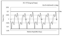
도 9는 실시예에 따른 모터의 제2 홈의 깊이 대비 제2 홈의 제2 거리가 1.578배인 경우 모터의 코깅 토크 파형을 나타내는 도면이고,
도 10은 실시예에 따른 모터의 제2 홈의 깊이 대비 제2 홈의 제2 거리가 1.315배인 경우 모터의 코깅 토크 및 토크의 변화를 나타내는 표이고,
도 11은 실시예에 따른 모터의 제2 홈의 깊이 대비 제2 홈의 제2 거리가 1.315배인 경우 모터의 코깅 토크를 나타내는 그래프이고,
도 12는 비교예인 모터의 코깅 토크 파형을 나타내는 도면이고,
도 13은 실시예에 따른 모터의 제2 홈의 깊이 대비 제2 홈의 제2 거리가 1.315배인 경우 모터의 코깅 토크 파형을 나타내는 도면이고,
도 14는 실시예에 따른 모터의 제2 홈의 깊이 대비 제2 홈의 제2 거리가 1.9725배인 경우 모터의 코깅 토크 및 토크의 변화를 나타내는 표이고,
도 15는 실시예에 따른 모터의 제2 홈의 깊이 대비 제2 홈의 제2 거리가 1.9725배인 경우 모터의 코깅 토크를 나타내는 그래프이고,
도 16은 비교예인 모터의 코깅 토크 파형을 나타내는 도면이고,
도 17은 실시예에 따른 모터의 제2 홈의 깊이 대비 제2 홈의 제2 거리가 1.9725배인 경우 모터의 코깅 토크 파형을 나타내는 도면이다. 1 is a view showing a motor according to an embodiment,
2 is a cross-sectional view showing a motor according to an embodiment,
3 is a view showing a stator core of a motor according to an embodiment,
4 is an enlarged view showing area A of FIG. 3,
5 is a view showing a unit stator core of a motor according to an embodiment,
6 is a table showing a change in the cogging torque and torque of the motor when the second distance of the second groove is 1.578 times the depth of the second groove of the motor according to the embodiment,
7 is a graph showing the cogging torque of the motor when the second distance of the second groove is 1.578 times the depth of the second groove of the motor according to the embodiment,
8 is a view showing a cogging torque waveform of a motor as a comparative example,
9 is a diagram showing a cogging torque waveform of the motor when the second distance of the second groove is 1.578 times the depth of the second groove of the motor according to the embodiment,
10 is a table showing a change in the cogging torque and torque of the motor when the second distance of the second groove is 1.315 times the depth of the second groove of the motor according to the embodiment,
11 is a graph showing the cogging torque of the motor when the second distance of the second groove is 1.315 times the depth of the second groove of the motor according to the embodiment,
12 is a view showing a cogging torque waveform of a motor as a comparative example,
13 is a view showing a cogging torque waveform of the motor when the second distance of the second groove is 1.315 times the depth of the second groove of the motor according to the embodiment,
14 is a table showing changes in cogging torque and torque of the motor when the second distance of the second groove is 1.9725 times compared to the depth of the second groove of the motor according to the embodiment,
15 is a graph showing the cogging torque of the motor when the second distance of the second groove is 1.9725 times the depth of the second groove of the motor according to the embodiment,
16 is a diagram showing a cogging torque waveform of a motor as a comparative example,
FIG. 17 is a diagram showing a cogging torque waveform of a motor when the second distance of the second groove is 1.9725 times the depth of the second groove of the motor according to the embodiment.
본 발명은 다양한 변경을 가할 수 있고 여러 가지 실시예를 가질 수 있는 바, 특정 실시예들을 도면에 예시하고 설명하고자 한다. 그러나, 이는 본 발명을 특정한 실시 형태에 대해 한정하려는 것이 아니며, 본 발명의 사상 및 기술 범위에 포함되는 모든 변경, 균등물 내지 대체물을 포함하는 것으로 이해되어야 한다. The present invention can be applied to various changes and can have various embodiments, and specific embodiments will be illustrated and described in the drawings. However, this is not intended to limit the present invention to specific embodiments, and should be understood to include all modifications, equivalents, and substitutes included in the spirit and scope of the present invention.
제2, 제1 등과 같이 서수를 포함하는 용어는 다양한 구성요소들을 설명하는데 사용될 수 있지만, 상기 구성요소들은 상기 용어들에 의해 한정되지는 않는다. 상기 용어들은 하나의 구성요소를 다른 구성요소로부터 구별하는 목적으로만 사용된다. 예를 들어, 본 발명의 권리 범위를 벗어나지 않으면서 제2 구성요소는 제1 구성요소로 명명될 수 있고, 유사하게 제1 구성요소도 제2 구성요소로 명명될 수 있다. 및/또는 이라는 용어는 복수의 관련된 기재된 항목들의 조합 또는 복수의 관련된 기재된 항목들 중의 어느 항목을 포함한다. Terms including ordinal numbers such as second and first may be used to describe various components, but the components are not limited by the terms. The terms are used only for the purpose of distinguishing one component from other components. For example, the second component may be referred to as a first component without departing from the scope of the present invention, and similarly, the first component may also be referred to as a second component. The term and/or includes a combination of a plurality of related described items or any one of a plurality of related described items.
어떤 구성요소가 다른 구성요소에 "연결되어" 있다거나 "접속되어" 있다고 언급된 때에는, 그 다른 구성요소에 직접적으로 연결되어 있거나 또는 접속되어 있을 수도 있지만, 중간에 다른 구성요소가 존재할 수도 있다고 이해되어야 할 것이다. 반면에, 어떤 구성요소가 다른 구성요소에 "직접 연결되어" 있다거나 "직접 접속되어" 있다고 언급된 때에는, 중간에 다른 구성요소가 존재하지 않는 것으로 이해되어야 할 것이다. When an element is said to be "connected" or "connected" to another component, it is understood that other components may be directly connected to or connected to the other component, but there may be other components in between. It should be. On the other hand, when a component is said to be "directly connected" or "directly connected" to another component, it should be understood that no other component exists in the middle.
실시 예의 설명에 있어서, 어느 한 구성요소가 다른 구성요소의 " 상(위) 또는 하(아래)(on or under)"에 형성되는 것으로 기재되는 경우에 있어, 상(위) 또는 하(아래)(on or under)는 두 개의 구성요소가 서로 직접(directly)접촉되거나 하나 이상의 다른 구성요소가 상기 두 구성요소 사이에 배치되어(indirectly) 형성되는 것을 모두 포함한다. 또한 '상(위) 또는 하(아래)(on or under)'로 표현되는 경우 하나의 구성요소를 기준으로 위쪽 방향뿐만 아니라 아래쪽 방향의 의미도 포함할 수 있다.In the description of the embodiment, when one component is described as being formed on the "on (up) or down (down)" (on or under) of the other component, the top (top) or bottom (bottom) (on or under) includes both two components directly contacting each other or one or more other components formed indirectly between the two components. In addition, when expressed as'on (up) or down (on or under)', it may include the meaning of the downward direction as well as the upward direction based on one component.
본 출원에서 사용한 용어는 단지 특정한 실시예를 설명하기 위해 사용된 것으로, 본 발명을 한정하려는 의도가 아니다. 단수의 표현은 문맥상 명백하게 다르게 뜻하지 않는 한, 복수의 표현을 포함한다. 본 출원에서, "포함하다" 또는 "가지다" 등의 용어는 명세서상에 기재된 특징, 숫자, 단계, 동작, 구성요소, 부품 또는 이들을 조합한 것이 존재함을 지정하려는 것이지, 하나 또는 그 이상의 다른 특징들이나 숫자, 단계, 동작, 구성요소, 부품 또는 이들을 조합한 것들의 존재 또는 부가 가능성을 미리 배제하지 않는 것으로 이해되어야 한다.The terms used in this application are only used to describe specific embodiments, and are not intended to limit the present invention. Singular expressions include plural expressions unless the context clearly indicates otherwise. In this application, terms such as “include” or “have” are intended to indicate that a feature, number, step, operation, component, part, or combination thereof described in the specification exists, and that one or more other features are present. It should be understood that the existence or addition possibilities of fields or numbers, steps, operations, components, parts or combinations thereof are not excluded in advance.
다르게 정의되지 않는 한, 기술적이거나 과학적인 용어를 포함해서 여기서 사용되는 모든 용어들은 본 발명이 속하는 기술 분야에서 통상의 지식을 가진 자에 의해 일반적으로 이해되는 것과 동일한 의미를 가지게 된다. 일반적으로 사용되는 사전에 정의되어 있는 것과 같은 용어들은 관련 기술의 문맥상 가지는 의미와 일치하는 의미를 가지는 것으로 해석되어야 하며, 본 출원에서 명백하게 정의하지 않는 한, 이상적이거나 과도하게 형식적인 의미로 해석되지 않는다.Unless otherwise defined, all terms used herein, including technical or scientific terms, have the same meaning as commonly understood by a person skilled in the art to which the present invention pertains. Terms, such as those defined in a commonly used dictionary, should be interpreted as having meanings consistent with meanings in the context of related technologies, and should not be interpreted as ideal or excessively formal meanings unless explicitly defined in the present application. Does not.
이하, 첨부된 도면을 참조하여 실시예를 상세히 설명하되, 도면 부호에 관계없이 동일하거나 대응하는 구성 요소는 동일한 참조 번호를 부여하고 이에 대한 중복되는 설명은 생략하기로 한다. Hereinafter, exemplary embodiments will be described in detail with reference to the accompanying drawings, but the same or corresponding components are assigned the same reference numbers regardless of reference numerals, and overlapping descriptions thereof will be omitted.
도 1은 실시예에 따른 모터를 나타내는 도면이고, 도 2는 실시예에 따른 모터를 나타내는 단면도이다. 여기서, 도 2는 도 1의 A-A선을 나타내는 단면도이다. 그리고, 도 1에서 y 방향은 축 방향을 의미하며, x 방향은 반경 방향을 의미할 수 있다. 그리고, 축 방향과 반경 방향은 서로 수직할 수 있다. 그리고, 상기 축 방향은 샤프트(500)의 길이 방향일 수 있다. 1 is a view showing a motor according to an embodiment, and FIG. 2 is a cross-sectional view showing a motor according to an embodiment. Here, FIG. 2 is a cross-sectional view showing line A-A in FIG. 1. In addition, in FIG. 1, the y direction means an axial direction, and the x direction may mean a radial direction. And, the axial direction and the radial direction may be perpendicular to each other. In addition, the axial direction may be the longitudinal direction of the
도 1 및 도 2를 참조하면, 실시예에 따른 모터(1)는 일측에 개구가 형성된 하우징(100), 하우징(100)의 상부에 배치되는 커버(200), 하우징(100)의 내부에 배치되는 스테이터(300), 스테이터(300)의 내측에 배치되는 로터(400) 및 로터(400)와 함께 회전하는 샤프트(500), 스테이터(300)의 상측에 배치되는 버스바(600) 및 샤프트(500)의 회전을 감지하는 센서부(700)를 포함할 수 있다. 여기서, 내측이라 함은 상기 반경 방향을 기준으로 중심인 축(C)을 향하여 배치되는 방향을 의미하고, 외측이라 함은 내측과 반대되는 방향을 의미한다.1 and 2, the
하우징(100)과 커버(200)는 상기 모터(1)의 외형을 형성할 수 있다. 여기서, 하우징(100)은 상부에 개구가 형성된 통 형상으로 형성될 수 있다. The
상기 커버(200)는 하우징(100)의 개방된 상부를 덮도록 배치될 수 있다. The
따라서, 하우징(100)과 커버(200)의 결합에 의해 내부에 수용공간이 형성될 수 있다. 그리고, 상기 수용공간에는, 도 1에 도시된 바와 같이, 스테이터(300), 로터(400), 샤프트(500), 버스바(600) 및 센서부(700) 등이 배치될 수 있다.Therefore, an accommodation space may be formed inside by combining the
하우징(100)은 원통형으로 형성될 수 있다. 하우징(100)의 하부에는 샤프트(500)의 하부를 지지하는 베어링(10)을 수용하는 포켓부가 마련될 수 있다. 또한, 하우징(100)의 상부에 배치되는 커버(200)에도 샤프트(500)의 상부를 지지하는 베어링(10)을 수용하는 포켓부가 마련될 수 있다. The
스테이터(300)는 하우징(100)의 내주면에 의해 지지될 수 있다. 그리고, 스테이터(300)는 로터(400)의 외측에 배치된다. 즉, 스테이터(300)의 내측에는 로터(400)가 배치될 수 있다.The
도 3은 실시예에 따른 모터의 스테이터 코어를 나타내는 단면도이고, 도 4는 도 3의 A영역을 나타내는 확대도이고, 도 5는 실시예에 따른 모터의 단위 스테이터 코어를 나타내는 도면이다. 3 is a cross-sectional view showing a stator core of a motor according to an embodiment, FIG. 4 is an enlarged view showing a region A of FIG. 3, and FIG. 5 is a view showing a unit stator core of a motor according to an embodiment.
도 1 내지 4를 참조하면, 스테이터(300)는 스테이터 코어(310), 스테이터 코어(310)에 권선되는 코일(320), 스테이터 코어(310)와 코일(320) 사이에 배치되는 인슐레이터(330)를 포함할 수 있다. 1 to 4, the
스테이터 코어(310)에는 회전 자계를 형성하는 코일(320)이 권선될 수 있다. 여기서, 스테이터 코어(310)는 하나의 코어로 이루어질 수 있다. 또는, 스테이터 코어(310)는 도 5에 도시된 복수 개의 단위 스테이터 코어(310a)를 원주 방향을 따라 배치하여 형성할 수 있다. A
또한, 스테이터 코어(310)는 얇은 강판 형태의 복수 개의 플레이트가 상호 적층된 형태로 이루어질 수 있으나 반드시 이에 한정되는 것은 아니다. 예컨데, 스테이터 코어(310)는 하나의 단일품으로 형성될 수도 있다. In addition, the
스테이터 코어(310)는 요크(311), 요크(311)에서 반경 방향으로 돌출된 투스(312) 및 투스(312)의 내면(313)에 형성된 제1 홈(314)과 제2 홈(315)을 포함할 수 있다. 여기서, 투스(312)의 원주 방향 중심을 기준으로 제1 홈(314)과 제2 홈(315)까지의 이격 거리는 서로 상이할 수 있다. 그에 따라, 제1 홈(314)과 제2 홈(315)은 투스(312)의 내면(313)에 비대칭적으로 배치될 수 있다. The
스테이터 코어(310)의 요크(311)는 원통 형상으로 형성될 수 있다. 그리고, 단위 스테이터 코어(310a)의 요크(311)는 호 형상으로 형성될 수 있다. The
상기 투스(312)는 축(C)을 기준으로 반경 방향(x 방향)을 향해 요크(311)에서 돌출되게 배치될 수 있다. 그리고, 복수 개의 상기 투스(312)는 원주 방향을 따라 스테이터 코어(310)의 요크(311)의 내주면에 서로 이격되게 배치될 수 있다. 그에 따라, 각각의 상기 투스(312) 사이에는 코일(320)이 권선될 수 있는 공간인 슬롯이 형성될 수 있다. 이때, 상기 투스(312)는 12개로 제공될 수 있으나 반드시 이에 한정되지 않는다.The
한편, 상기 투스(312)는 로터(400)의 마그넷(420)을 대향하도록 배치될 수 있다. 이때, 반경 방향을 기준으로 투스(312)의 내면(313)은 마그넷(420)의 외주면과 소정의 간격으로 이격되게 배치된다. 여기서, 상기 내면(313)은 상기 모터(1)의 축(C)을 기준으로 소정의 곡률(1/R)로 형성될 수 있다. 그에 따라, 상기 투스(312)의 상기 내면(313)의 길이는 호의 길이를 구하는 공식에 의해 구해질 수 있다. Meanwhile, the
각각의 상기 투스(312)에는 코일(320)이 감긴다.A
투스(312)는 코일(320)이 권선되는 바디(312a) 및 바디(312a)의 내측 단부에 배치되는 돌기부(312b)를 포함할 수 있다. 여기서, 돌기부(312b)는 슈라 불릴 수 있다.The
바디(312a)는 축(C)을 기준으로 반경 방향(x 방향)을 향해 요크(311)에서 돌출되게 배치될 수 있다. 그리고, 바디(312a)는 원주 방향을 따라 요크(311)의 내주면에 서로 이격되게 배치될 수 있다.The
그리고, 바디(312a)에는 코일(320)이 권선될 수 있다. In addition, the
돌기부(312b)는 바디(312a)의 단부에서 내측으로 돌출되게 연장될 수 있다. 이때, 돌기부(312b)의 원주 방향 폭은 바디(312a)의 원주 방향 폭보다 클 수 있다. The
돌기부(312b)가 원주 방향을 따라 서로 이격되게 배치됨에 따라, 상기 슬롯의 내측에는 개구부가 형성될 수 있다. 여기서, 상기 개구부는 슬롯 오픈을 의미한다. 예컨데, 상기 슬롯 오픈은 복수 개의 투스(312) 중 하나의 투스(312)의 돌기부(312b)의 일단과 인접한 다른 하나의 투스(312)의 돌기부(312b)의 타단 사이를 나타낼 수 있다. As the
따라서, 상기 슬롯 오픈은 어느 하나의 돌기부(312b)의 끝점(P)과 인접하게 배치되는 다른 하나의 돌기부(312b)의 끝점(P) 사이의 공간을 의미할 수 있으며, 상기 슬롯 오픈은 소정의 거리를 갖도록 배치될 수 있다. 여기서, 상기 슬롯 오픈의 거리는 돌기부(312b) 사이의 거리라 불리거나 또는 슬롯 오픈의 폭이라 불릴 수 있다. Accordingly, the slot open may mean a space between the end point P of one of the
투스(312)의 내면(313)은 상기 모터(1)의 축(C)을 기준으로 소정의 곡률(1/R)을 갖도록 형성될 수 있다. 여기서, 투스(312)의 내면(313)은 돌기부(312b)의 내면(313)일 수 있다. The
제1 홈(314)과 제2 홈(315)이 원주 방향으로 서로 이격되게 형성됨에 따라, 상기 내면(313)은 시계 방향을 기준으로 제1 내면(313a), 제2 내면(313b) 및 제3 내면(313c)을 포함할 수 있다. As the
제1 홈(314)과 제2 홈(315)은 내면(313)에 반경 방향으로 오목하게 형성될 수 있다. 그리고, 제1 홈(314)과 제2 홈(315)은 원주 방향으로 상호 이격되게 내면(313)에 배치될 수 있다. 도 5에 도시된 바와 같이, 제1 홈(314)과 제2 홈(315)은 샤프트(500)의 축 방향으로 내면(313)의 상단에서 하단까지 길게 형성될 수 있다. The
도 4를 참조하면, 투스(312)의 원주 방향 중심과 축(C)을 연결한 가상의 선(L)을 기준으로 제1 홈(314)과 제2 홈(315)까지의 이격 거리는 서로 상이할 수 있다. 여기서, 투스(312)의 원주 방향 중심은 내면(313)의 중심(C1)일 수 있다. 그에 따라, 상기 선(L) 상에 내면(313)의 중심(C1)이 배치될 수 있다. Referring to FIG. 4, the separation distances between the
따라서, 상기 투스(312)의 내면(313)의 중심(C1)과 상기 샤프트(500)의 축(C)을 연결한 가상의 선(L)에서 상기 제1 홈(314)의 일측까지의 제1 거리(D1)는 상기 선(L)에서 상기 제2 홈(315)의 타측까지의 제2 거리(D2)와 상이할 수 있다. 여기서, 상기 모터(1)의 코깅 토크를 고려하여 상기 제1 거리(D1)는 제2 거리(D2)보다 크거나 작을 수 있다. 그에 따라, 제1 홈(314)과 제2 홈(315)의 배치 위치는 투스(312)의 원주 방향 중심을 기준으로 비대칭적일 수 있다. Therefore, the virtual line (L) connecting the center (C1) of the inner surface (313) of the tooth (312) and the shaft (C) of the
즉, 상기 샤프트(500)의 축(C)을 기준으로, 상기 투스(312)의 내면(313)의 중심(C1)과 상기 샤프트(500)의 축(C)을 연결한 가상의 선(L)에서 상기 제1 홈(314)의 일측까지 상기 투스(312)의 내면(313)이 이루는 제1 각도(θ1)와 상기 선(L)에서 상기 제2 홈(315)의 타측까지 상기 투스(312)의 내면(313)이 이루는 제2 각도(θ2)는 서로 상이할 수 있다. That is, based on the axis C of the
제1 홈(314)과 제2 홈(315)을 설명함에 있어서, 원주 방향을 기준으로 시계 방향측을 일측이라하고 반시계 방향측을 타측이라 할 수 있다. 예컨데, 상기 제1 각도(θ1)는 상기 선(L)을 기준으로 제1 홈(314)의 일측까지의 거리를 나타내는 각도일 수 있으며, 상기 제2 각도(θ2)는 상기 선(L)을 기준으로 제2 홈(315)의 타측까지의 거리를 나타내는 각도일 수 있다. 여기서, 샤프트(500)의 축(C)은 스테이터 코어(310)의 중심과 동일할 수 있다. 그리고, 제1 각도(θ1)와 제2 각도(θ2)를 나타내는 내면(313)은 상기 제2 내면(313b)일 수 있다. In describing the
또한, 상기 샤프트(500)의 축을 기준으로, 상기 제1 홈(314)의 일측에서 상기 제2 홈(315)의 타측까지의 상기 투스(312)의 내면(313)이 이루는 제5 각도(θ5)는 상기 제1 홈(314)의 타측에서 상기 투스(312)의 타측까지의 상기 투스(312)의 내면(313)이 이루는 제3 각도(θ3) 및 상기 제2 홈(315)의 일측에서 상기 투스(312)의 내면(313)의 일측까지의 상기 투스(312)의 내면(313)이 이루는 제4 각도(θ4)와 다른 각도로 형성될 수 있다. In addition, the fifth angle θ5 formed by the
여기서, 상기 투스(312)의 내면(313)의 일측에서 상기 제2 홈(315)의 일측까지 상기 투스(312)의 내면(313)이 이루는 제4 각도(θ4)는 상기 제2 각도(θ2)의 2배일 수 있다. Here, the fourth angle θ4 formed by the
그리고, 제5 각도(θ5)는 축(C)을 기준으로 제2 내면(313b)의 원주 방향에 대한 일측과 타측이 이루는 각도일 수 있다. 이때, 제5 각도(θ5)는 제1 각도(θ1)와 제2 각도(θ2)를 나타낼 수 있다. 그에 따라, 제5 각도(θ5)는 상기 투스(312)의 내면(313)의 중심(C1)과 상기 샤프트(500)의 축(C)을 연결한 가상의 선(L)에서 상기 제1 홈(314)의 일측까지 상기 투스(312)의 내면(313)이 이루는 제1 각도(θ1)와 상기 선(L)에서 상기 제2 홈(315)의 타측까지 상기 투스(312)의 내면(313)이 이루는 제2 각도(θ2)의 합일 수 있다. 이때, 상기 제1 각도(θ1)와 상기 제2 각도(θ2)는 서로 상이할 수 있다. Further, the fifth angle θ5 may be an angle formed by one side and the other side with respect to the circumferential direction of the second
그리고, 제3 각도(θ3)는 축(C)을 기준으로 제1 내면(313a)의 원주 방향에 대한 일측과 타측이 이루는 각도일 수 있다. 그리고, 제4 각도(θ4)는 축(C)을 기준으로 제3 내면(313c)의 원주 방향에 대한 일측과 타측이 이루는 각도일 수 있다. In addition, the third angle θ3 may be an angle formed by one side and the other side with respect to the circumferential direction of the first
또한, 상기 제3 각도(θ3) 및 상기 제4 각도(θ4)는 서로 상이할 수 있다. Also, the third angle θ3 and the fourth angle θ4 may be different from each other.
또한, 제1 홈(314)이 상기 선(L)에서 이격되는 이격 거리인 제1 거리(D1)가 제2 홈(315)이 상기 선(L)에서 이격되는 이격 거리인 제2 거리(D2)보다 크거나 작을 수 있기 때문에, 상기 제5 각도(θ5)는 상기 제4 각도(θ4)보다 크거나 작을 수 있다. 예를 들어, 상기 제5 각도(θ5)가 상기 제4 각도(θ4)보다 더 큰 경우, 상기 제4 각도(θ4)는 상기 제3 각도(θ3)보다 클 수 있다. 그리고, 상기 제5 각도(θ5)가 상기 제4 각도(θ4)보다 더 작은 경우, 상기 제4 각도(θ4)는 상기 제3 각도(θ3)보다 작을 수 있다. In addition, a first distance D1, which is a separation distance from which the
따라서, 상기 투스(312)의 내면(313)의 타측에서 상기 제1 홈(314)까지의 제3 거리(D3)는 상기 투스(312)의 내면(313)의 일측에서 상기 제2 홈(315)까지의 제4 거리(D4)와 상이하다. Accordingly, the third distance D3 from the other side of the
한편, 제1 홈(314)과 제2 홈(315)의 크기는 동일할 수 있다. 예컨데, 제1 홈(314)과 제2 홈(315)의 반경 방향의 깊이(D) 및 원주 방향의 폭(W)은 동일한 사각형 형상으로 형성될 수 있다. Meanwhile, the sizes of the
여기서, 제1 홈(314)의 원주 방향의 폭(W)을 1이라 할 때, 제1 홈(314)의 원주 방향의 폭(W)에 대한 깊이(D)의 비율은 0.24~0.29일 수 있다. 즉, 제1 홈(314)의 깊이(D)는 제1 홈(314)의 폭(W)의 0.24~0.29배일 수 있다. Here, when the width W in the circumferential direction of the
또한, 상기 투스(312)의 내면(313)의 중심(C1)과 상기 샤프트(500)의 축(C)을 연결한 가상의 선(L)에서 상기 제2 홈(315)의 타측까지의 제2 거리(D2)는 상기 제2 홈(315)의 깊이(D)의 1.315~1.9725배일 수 있다. 상세하게, 상기 모터(1)의 코깅 토크를 고려하여 제2 거리(D2)는 상기 제2 홈(315)의 깊이(D)의 1.315~1.578배일 수 있다. In addition, from the virtual line (L) connecting the center (C1) of the inner surface (313) of the tooth (312) and the axis (C) of the
상기 모터(1)의 제1 홈(314)과 제2 홈(315)은 상기 선(L)에 대해 비대칭되게 상기 투스(312)의 내면(313)에 형성될 수 있으며, 상기 선(L)을 기준으로 제1 홈(314)의 이격된 제1 거리(D1)에 의해 코깅 토크는 감소될 수 있다. The
즉, 상기 모터(1)는 상기 선(L)을 기준으로 제1 홈(314)의 이격 거리인 제1 거리(D1)와 제2 홈(315)의 이격 거리인 제2 거리(D2)를 다르게 설계하여 코깅 토크를 저감시킬 수 있다. 이때, 상기 투스(312)의 내면(313)의 일측에서 상기 제2 홈(315)까지의 제4 거리(D4)는 상기 제2 거리(D2)의 2배일 수 있다.That is, the motor (1) is based on the line (L), the first distance (D1) that is the separation distance of the first groove (314) and the second distance (D2) that is the separation distance of the second groove (315) It can be designed differently to reduce cogging torque. In this case, the fourth distance D4 from one side of the
그에 따라, 상기 샤프트(500)의 축(C)을 기준으로, 상기 제1 각도(θ1)는 상기 제2 각도(θ2)는 서로 상이할 수 있다. Accordingly, based on the axis C of the
따라서, 상기 모터(1)는 상기 제2 각도(θ2)를 설계 기준값으로 제공하고, 이를 기초로 상기 제1 각도(θ1)를 다르게 형성함으로써 코깅 토크를 감소시킬 수 있다. 여기서, 상기 제4 각도(θ4)는 상기 제2 각도(θ2)의 2배일 수 있다. Accordingly, the
예컨데, 상기 모터(1)는 투스(312)의 내면(313)의 중심(C1)에서 떨어져 배치되는 제2 홈(315)의 제2 거리(D2) 또는 제2 각도(θ2)와의 관계에서 홈의 깊이(D)를 제시하고, 이를 기반으로 제1 거리(D1) 또는 제1 각도(θ1)의 배치 위치를 설정하여 상기 모터(1)의 코깅 토크를 감소시킬 수 있다. For example, the
도 6은 실시예에 따른 모터의 제2 홈의 깊이 대비 제2 홈의 제2 거리가 1.578배인 경우 모터의 코깅 토크 및 토크의 변화를 나타내는 표이고, 도 7은 실시예에 따른 모터의 제2 홈의 깊이 대비 제2 홈의 제2 거리가 1.578배인 경우 모터의 코깅 토크를 나타내는 그래프이고, 도 8은 비교예인 모터의 코깅 토크 파형을 나타내는 도면이고, 도 9는 실시예에 따른 모터의 제2 홈의 깊이 대비 제2 홈의 제2 거리가 1.578배인 경우 제1 각도가 2.4deg일 때 모터의 코깅 토크 파형을 나타내는 도면이다. 여기서, 비교예로 제시되는 모터는 제1 홈(314)의 제1 각도(θ2)와 제2 홈(315)의 제2 각도(θ2)가 동일한 경우를 나타낸다. 그리고, 상기 모터(1)에 있어서, 제2 홈(315)의 제2 거리(D2)는 제2 홈(315)의 깊이(D)의 1.578배일 수 있다. 예컨데, 제2 홈(315)의 제2 거리(D2)가 0.789mm일 때, 상기 제2 홈(315)의 깊이(D)는 0.5mm일 수 있다. 이때, 제1 홈(314)의 깊이는 제2 홈(315)의 깊이와 동일하다. 6 is a table showing a change in cogging torque and torque of the motor when the second distance of the second groove is 1.578 times the depth of the second groove of the motor according to the embodiment, and FIG. 7 is the second of the motor according to the embodiment When the second distance of the second groove to the depth of the groove is 1.578 times, it is a graph showing the cogging torque of the motor, FIG. 8 is a diagram showing the waveform of the cogging torque of the motor as a comparative example, and FIG. When the second distance of the second groove to the depth of the groove is 1.578 times, this is a diagram showing the cogging torque waveform of the motor when the first angle is 2.4 deg. Here, the motor presented as a comparative example represents a case where the first angle θ2 of the
상기 모터(1)의 상기 제1 각도(θ1)는 제2 각도(θ2)보다 크거나 작게 형성될 수 있다. The first angle θ1 of the
도 6 및 도 7을 참조하면, 상기 제1 각도(θ1)와 상기 제2 각도(θ2)의 차이는 상기 제2 각도(θ2)의 크기의 10% 이내일 수 있다. 상세하게, 상기 제1 각도(θ1)는 상기 제2 각도(θ2)와 상기 제2 각도(θ2)의 10% 이내의 각도의 합(θ1=θ2+K1, K1≤θ2*10%)이거나, 또는 상기 제1 각도(θ1)는 상기 제2 각도(θ2)와 상기 제2 각도(θ2)의 5% 이내의 각도의 차(θ1=θ2-K2, K2≤θ2*5%)일 수 있다. 6 and 7, the difference between the first angle θ1 and the second angle θ2 may be within 10% of the size of the second angle θ2. Specifically, the first angle θ1 is a sum (θ1=θ2+K1, K1≤θ2*10%) of an angle within 10% of the second angle θ2 and the second angle θ2, or Alternatively, the first angle θ1 may be a difference (θ1=θ2-K2, K2≤θ2*5%) of an angle within 5% of the second angle θ2 and the second angle θ2.
그에 따라, 상기 제4 각도(θ4)는 상기 제3 각도(θ3)와 상기 제2 각도(θ2)의 10% 이내의 각도의 합(θ4=θ3+K1, K1≤θ2*10%)이거나, 또는, 상기 제4 각도(θ4)는 상기 제3 각도(θ3)와 상기 제2 각도(θ2)의 5% 이내의 각도의 차(θ4=θ3-K2, K2≤θ2*5%)일 수 있다. 이에, 상기 제4 각도(θ4)와 상기 제3 각도(θ3)의 차이는 상기 제4 각도(θ4)의 크기의 5% 이내일 수 있다.Accordingly, the fourth angle θ4 is a sum (θ4=θ3+K1, K1≤θ2*10%) of an angle within 10% of the third angle θ3 and the second angle θ2, or Alternatively, the fourth angle θ4 may be a difference (θ4=θ3-K2, K2≤θ2*5%) of an angle within 5% of the third angle θ3 and the second angle θ2. . Accordingly, the difference between the fourth angle θ4 and the third angle θ3 may be within 5% of the size of the fourth angle θ4.
또는, 상기 모터(1)의 상기 제1 거리(D1)는 상기 제2 거리(D2)보다 크거나 작게 형성될 수 있다. 상세하게, 상기 제1 거리(D1)는 상기 제2 거리(D2)와 상기 제2 거리(D2)의 10% 이내의 합(D1=D2+K1, K1≤D2*10%)이거나, 또는 제1 거리(D1)는 상기 제2 거리(D2)와 상기 제2 거리(D2)의 5% 이내의 차(D1=D2-K2, K2≤D2*5%)일 수 있다. Alternatively, the first distance D1 of the
도 6 및 도 7을 참조하면, 실시예에 따른 모터(1)는 비교예인 모터 대비 최대 4.6%(θ1=2.4deg)까지 코깅 토크가 저감될 수 있다. 6 and 7, the
상기 제1 각도(θ1)가 상기 제2 각도(θ2)보다 큰 경우, 상기 모터(1)의 코깅 토크는 제1 각도(θ1)가 2.4deg일 때까지 하락하다가 다시 증가하는 것을 확인할 수 있다. 또한, 상기 제1 각도(θ1)가 상기 제2 각도(θ2)보다 작은 경우, 상기 모터(1)의 코깅 토크는 제1 각도(θ1)가 2.1deg일 때까지 하락하다가 다시 증가하는 것을 확인할 수 있다. 이때, 비교예인 모터의 토크 결과치인 6.01Nm 대비 실시예에 따른 모터(1)의 토크의 변화량이 미미함을 확인할 수 있다. When the first angle θ1 is greater than the second angle θ2, it can be seen that the cogging torque of the
따라서, 상기 제1 각도(θ1)가 상기 제2 각도(θ2)보다 8.6% 크게 형성되는 경우, 상기 모터(1)의 코깅 토크는 최소값을 갖게 된다. 그리고, 상기 제1 각도(θ1)가 상기 제2 각도(θ2)보다 5% 작게 형성되는 경우, 상기 모터(1)의 코깅 토크는 두번째로 작은 값을 갖게 된다. Accordingly, when the first angle θ1 is formed 8.6% larger than the second angle θ2, the cogging torque of the
도 8 및 도 9에 도시된 맥동(반복 토크 파형)을 참조하면, 상기 모터(1)의 코깅 토크의 최대값과 최소값의 진폭은 비교예인 모터의 코깅 토크의 최대값과 최소값의 폭보다 작음을 확인할 수 있다. 그에 따라, 상기 모터(1)의 코깅 토크가 저감되는 것을 확인할 수 있다. 8 and 9, the amplitudes of the maximum and minimum values of the cogging torque of the
도 10은 실시예에 따른 모터의 제2 홈의 깊이 대비 제2 홈의 제2 거리가 1.315배인 경우 모터의 코깅 토크 및 토크의 변화를 나타내는 표이고, 도 11은 실시예에 따른 모터의 제2 홈의 깊이 대비 제2 홈의 제2 거리가 1.315배인 경우 모터의 코깅 토크를 나타내는 그래프이고, 도 12는 비교예인 모터의 코깅 토크 파형을 나타내는 도면이고, 도 13은 실시예에 따른 모터의 제2 홈의 깊이 대비 제2 홈의 제2 거리가 1.315배인 경우 제1 각도가 2.3deg일 때 모터의 코깅 토크 파형을 나타내는 도면이다. 여기서, 비교예로 제시되는 모터는 제1 홈(314)의 제1 각도(θ2)와 제2 홈(315)의 제2 각도(θ2)가 동일한 경우를 나타낸다. 그리고, 상기 모터(1)에 있어서, 제2 홈(315)의 제2 거리(D2)는 제2 홈(315)의 깊이(D)의 1.315배일 수 있다. 예컨데, 제2 홈(315)의 제2 거리(D2)가 0.789mm일 때, 상기 제2 홈(315)의 깊이(D)는 0.6mm일 수 있다. 이때, 제1 홈(314)의 깊이는 제2 홈(315)의 깊이와 동일하다. 10 is a table showing a change in the cogging torque and torque of the motor when the second distance of the second groove is 1.315 times the depth of the second groove of the motor according to the embodiment, and FIG. 11 is the second of the motor according to the embodiment When the second distance of the second groove to the depth of the groove is 1.315 times, it is a graph showing the cogging torque of the motor, FIG. 12 is a diagram showing the waveform of the cogging torque of the motor as a comparative example, and FIG. It is a diagram showing the cogging torque waveform of the motor when the first angle is 2.3 deg when the second distance of the second groove to the depth of the groove is 1.315 times. Here, the motor presented as a comparative example represents a case where the first angle θ2 of the
상기 모터(1)의 상기 제1 각도(θ1)는 제2 각도(θ2)보다 크거나 작게 형성될 수 있다. The first angle θ1 of the
도 10 및 도 11을 참조하면, 상기 제1 각도(θ1)와 상기 제2 각도(θ2)의 차이는 상기 제2 각도(θ2)의 크기의 5% 이내일 수 있다. 상세하게, 상기 제1 각도(θ1)는 상기 제2 각도(θ2)와 상기 제2 각도(θ2)의 4% 이내의 각도의 합(θ1=θ2+K1, K1≤θ2*4%)이거나, 또는 상기 제1 각도(θ1)는 상기 제2 각도(θ2)와 상기 제2 각도(θ2)의 5% 이내의 각도의 차(θ1=θ2-K2, K2≤θ2*5%)일 수 있다. 10 and 11, the difference between the first angle θ1 and the second angle θ2 may be within 5% of the size of the second angle θ2. Specifically, the first angle θ1 is a sum (θ1=θ2+K1, K1≤θ2*4%) of an angle within 4% of the second angle θ2 and the second angle θ2, or Alternatively, the first angle θ1 may be a difference (θ1=θ2-K2, K2≤θ2*5%) of an angle within 5% of the second angle θ2 and the second angle θ2.
그에 따라, 상기 제4 각도(θ4)는 상기 제3 각도(θ3)와 상기 제2 각도(θ2)의 4% 이내의 각도의 합(θ4=θ3+K1, K1≤θ2*4%)이거나, 상기 제4 각도(θ4)는 상기 제3 각도(θ3)와 상기 제2 각도(θ2)의 5% 이내의 각도의 차(θ4=θ3-K2, K2≤θ2*5%)일 수 있다. Accordingly, the fourth angle θ4 is a sum (θ4=θ3+K1, K1≤θ2*4%) of an angle within 4% of the third angle θ3 and the second angle θ2, or The fourth angle θ4 may be a difference (θ4=θ3-K2, K2≤θ2*5%) of an angle within 5% of the third angle θ3 and the second angle θ2.
이에, 상기 제4 각도(θ4)와 상기 제3 각도(θ3)의 차이는 상기 제4 각도(θ4)의 크기의 2.5% 이내일 수 있다. Accordingly, the difference between the fourth angle θ4 and the third angle θ3 may be within 2.5% of the size of the fourth angle θ4.
또는, 상기 모터(1)의 상기 제1 거리(D1)는 상기 제2 거리(D2)보다 크거나 작게 형성될 수 있다. 상세하게, 상기 제1 거리(D1)는 상기 제2 거리(D2)와 상기 제2 거리(D2)의 4% 이내의 합(D1=D2+K1, K1≤D2*4%)이거나, 또는 제1 거리(D1)는 상기 제2 거리(D2)와 상기 제2 거리(D2)의 5% 이내의 차(D1=D2-K2, K2≤D2*5%)일 수 있다. Alternatively, the first distance D1 of the
도 10 및 도 11을 참조하면, 실시예에 따른 모터(1)는 비교예인 모터 대비 최대 17.3%(θ1=2.3deg)까지 코깅 토크가 저감될 수 있다. Referring to FIGS. 10 and 11, the
상기 제1 각도(θ1)가 상기 제2 각도(θ2)보다 큰 경우, 상기 모터(1)의 코깅 토크는 제1 각도(θ1)가 2.3deg일 때까지 하락하다가 다시 증가하는 것을 확인할 수 있다. 또한, 상기 제1 각도(θ1)가 상기 제2 각도(θ2)보다 작은 경우, 상기 모터(1)의 코깅 토크는 제1 각도(θ1)가 2.2deg일 때까지 하락하다가 다시 증가하는 것을 확인할 수 있다. 이때, 비교예인 모터의 토크 결과치인 6.01Nm 대비 실시예에 따른 모터(1)의 토크의 변화량이 없음을 확인할 수 있다. When the first angle θ1 is greater than the second angle θ2, it can be seen that the cogging torque of the
따라서, 상기 제1 각도(θ1)가 상기 제2 각도(θ2)보다 4% 크게 형성되는 경우, 상기 모터(1)의 코깅 토크는 최소값을 갖게 된다. 그리고, 상기 제1 각도(θ1)가 상기 제2 각도(θ2)보다 0.5% 작게 형성되는 경우, 상기 모터(1)의 코깅 토크는 두번째로 작은 값을 갖게 된다. Therefore, when the first angle θ1 is formed 4% larger than the second angle θ2, the cogging torque of the
도 12 및 도 13에 도시된 맥동(반복 토크 파형)을 참조하면, 상기 모터(1)의 코깅 토크의 최대값과 최소값의 진폭은 비교예인 모터의 코깅 토크의 최대값과 최소값의 폭보다 작음을 확인할 수 있다. 그에 따라, 상기 모터(1)의 코깅 토크가 저감되는 것을 확인할 수 있다. 12 and 13, the amplitudes of the maximum and minimum values of the cogging torque of the
도 14는 실시예에 따른 모터의 제2 홈의 깊이 대비 제2 홈의 제2 거리가 1.9725배인 경우 모터의 코깅 토크 및 토크의 변화를 나타내는 표이고, 도 15는 실시예에 따른 모터의 제2 홈의 깊이 대비 제2 홈의 제2 거리가 1.9725배인 경우 모터의 코깅 토크를 나타내는 그래프이고, 도 16은 비교예인 모터의 코깅 토크 파형을 나타내는 도면이고, 도 17은 실시예에 따른 모터의 제2 홈의 깊이 대비 제2 홈의 제2 거리가 1.9725배인 경우 제1 각도가 2.4deg일 때 모터의 코깅 토크 파형을 나타내는 도면이다. 여기서, 비교예로 제시되는 모터는 제1 홈(314)의 제1 각도(θ2)와 제2 홈(315)의 제2 각도(θ2)가 동일한 경우를 나타낸다. 그리고, 상기 모터(1)에 있어서, 제2 홈(315)의 제2 거리(D2)는 제2 홈(315)의 깊이(D)의 1.9725배일 수 있다. 예컨데, 제2 홈(315)의 제2 거리(D2)가 0.789mm일 때, 상기 제2 홈(315)의 깊이(D)는 0.6mm일 수 있다. 이때, 제1 홈(314)의 깊이는 제2 홈(315)의 깊이와 동일하다. 14 is a table showing changes in cogging torque and torque of a motor when the second distance of the second groove is 1.9725 times compared to the depth of the second groove of the motor according to the embodiment, and FIG. 15 is a second view of the motor according to the embodiment When the second distance of the second groove to the depth of the groove is 1.9725 times, it is a graph showing the cogging torque of the motor, FIG. 16 is a diagram showing the waveform of the cogging torque of the motor as a comparative example, and FIG. When the second distance of the second groove to the depth of the groove is 1.9725 times, this is a diagram showing the waveform of the motor's cogging torque when the first angle is 2.4 deg. Here, the motor presented as a comparative example represents a case where the first angle θ2 of the
상기 모터(1)의 상기 제1 각도(θ1)는 제2 각도(θ2)보다 크거나 작게 형성될 수 있다. The first angle θ1 of the
도 14 및 도 15를 참조하면, 상기 제1 각도(θ1)와 상기 제2 각도(θ2)의 차이는 상기 제2 각도(θ2)의 크기의 10% 이내일 수 있다. 상세하게, 상기 제1 각도(θ1)는 상기 제2 각도(θ2)와 상기 제2 각도(θ2)의 10% 이내의 각도의 합(θ1=θ2+K1, K1≤θ2*10%)이거나, 또는 상기 제1 각도(θ1)는 상기 제2 각도(θ2)와 상기 제2 각도(θ2)의 0.5% 이내의 각도의 차(θ1=θ2-K2, K2≤θ2*0.5%)일 수 있다. 14 and 15, a difference between the first angle θ1 and the second angle θ2 may be within 10% of the size of the second angle θ2. Specifically, the first angle θ1 is a sum (θ1=θ2+K1, K1≤θ2*10%) of an angle within 10% of the second angle θ2 and the second angle θ2, or Alternatively, the first angle θ1 may be a difference (θ1=θ2-K2, K2≤θ2*0.5%) of an angle within 0.5% of the second angle θ2 and the second angle θ2.
또는, 상기 모터(1)의 상기 제1 거리(D1)는 상기 제2 거리(D2)보다 크거나 작게 형성될 수 있다. 상세하게, 상기 제1 거리(D1)는 상기 제2 거리(D2)와 상기 제2 거리(D2)의 10% 이내의 합(D1=D2+K1, K1≤D2*10%)이거나, 또는 제1 거리(D1)는 상기 제2 거리(D2)와 상기 제2 거리(D2)의 0.5% 이내의 차(D1=D2-K2, K2≤D2*0.5%)일 수 있다. Alternatively, the first distance D1 of the
도 14 및 도 15를 참조하면, 실시예에 따른 모터(1)는 비교예인 모터 대비 최대 3.5%(θ1=2.4deg)까지 코깅 토크가 저감될 수 있다. 14 and 15, the
상기 제1 각도(θ1)가 상기 제2 각도(θ2)보다 큰 경우, 상기 모터(1)의 코깅 토크는 제1 각도(θ1)가 2.4deg일 때까지 하락하다가 다시 증가하는 것을 확인할 수 있다. 또한, 상기 제1 각도(θ1)가 상기 제2 각도(θ2)보다 작은 경우, 상기 모터(1)의 코깅 토크는 제1 각도(θ1)가 2.2deg일 때까지 하락하다가 다시 증가하는 것을 확인할 수 있다. 이때, 비교예인 모터의 토크 결과치인 6.09Nm 대비 실시예에 따른 모터(1)의 토크의 변화량이 없음을 확인할 수 있다. When the first angle θ1 is greater than the second angle θ2, it can be seen that the cogging torque of the
따라서, 상기 제1 각도(θ1)가 상기 제2 각도(θ2)보다 8.6% 크게 형성되는 경우, 상기 모터(1)의 코깅 토크는 최소값을 갖게 된다. Accordingly, when the first angle θ1 is formed 8.6% larger than the second angle θ2, the cogging torque of the
도 16 및 도 17에 도시된 맥동(반복 토크 파형)을 참조하면, 상기 모터(1)의 코깅 토크의 최대값과 최소값의 진폭은 비교예인 모터의 코깅 토크의 최대값과 최소값의 폭보다 작음을 확인할 수 있다. 그에 따라, 상기 모터(1)의 코깅 토크가 저감되는 것을 확인할 수 있다. 16 and 17, the amplitudes of the maximum and minimum values of the cogging torque of the
인슐레이터(330)는 스테이터 코어(310)와 코일(320)을 절연시킨다. 그에 따라, 인슐레이터(330)는 스테이터 코어(310)와 코일(320) 사이에 배치될 수 있다. The
따라서, 코일(320)은 인슐레이터(330)가 배치된 스테이터 코어(310)의 투스(312)에 권선될 수 있다. Accordingly, the
로터(400)는 스테이터(300)의 내측에 배치된다. 그리고, 로터(400)는 중심부에 샤프트(500)가 삽입되는 홀을 포함할 수 있다. 그에 따라, 로터(400)의 상기 홈에는 샤프트(500)가 결합될 수 있다. The
도 2를 참조하면, 로터(400)는 로터 코어(410), 로터 코어(410)의 외주면에 배치되는 마그넷(420)을 포함할 수 있다. 여기서, 마그넷(420)은 8개로 제공될 수 있으나 반드시 이에 한정되지 않는다. Referring to FIG. 2, the
도 2에 도시된 바와 같이, 로터(400)는 마그넷(420)이 로터 코어(410)의 외주면에 결합되는 타입으로 구현될 수 있다. 이러한 타입의 로터(400)는 마그넷(420)의 이탈을 방지하고 결합력을 높이기 위하여 별도의 캔부재(미도시)가 로터 코어(410)에 결합될 수 있다. 또는 마그넷(420)과 로터 코어(410)가 이중 사출되어 일체로 형성될 수 있다.As illustrated in FIG. 2, the
또는, 로터(400)는 마그넷(420)이 로터 코어(410)의 내부에 결합되는 타입으로 구현될 수도 있다. 이러한 타입의 로터(400)는 로터 코어(410) 내부에 마그넷(420)이 삽입되는 포켓이 마련될 수 있다. Alternatively, the
로터 코어(410)는 얇은 강판 형태의 복수 개의 플레이트가 상호 적층되어 이루어질 수 있다. 물론, 로터 코어(410)는 하나의 통으로 구성되는 단일 코어 형태로 제작될 수도 있다.The
또한, 로터 코어(410)는 스큐(skew)각을 형성하는 복수 개의 퍽(Puck)(단위 코어)이 적층되는 형태로 이루어질 수도 있다.In addition, the
한편, 로터 코어(410)는 샤프트(500)가 삽입되게 형성된 홀을 포함할 수 있다. Meanwhile, the
샤프트(500)는 로터(400)에 결합될 수 있다. 전류 공급을 통해 로터(400)와 스테이터(300)에 전자기적 상호 작용이 발생하면 로터(400)가 회전하고 이에 연동하여 샤프트(500)가 회전한다. 이때, 샤프트(500)는 베어링(10)에 의해 지지될 수 있다.The
샤프트(500)는, 도 1에 도시된 바와 같이, 베어링(10)에 의해 하우징(100)과 커버(200)의 내부에 회전 가능하게 지지될 수 있다.The
샤프트(500)는 차량의 조향축과 연결될 수 있다. 그에 따라, 샤프트(500)의 회전에 의해 상기 조향축은 동력을 전달받을 수 있다. The
버스바(600)는 스테이터(300)의 상부에 배치될 수 있다.The
그리고, 버스바(600)는 스테이터(300)의 코일(320)과 전기적으로 연결될 수 있다.In addition, the
버스바(600)는 버스바 바디(미도시)와 상기 버스바 바디에 배치되는 복수 개의 터미널(미도시)을 포함할 수 있다. The
상기 버스바 바디는 사출 성형을 통해 형성된 링 형상의 몰드물일 수 있다. 그리고, 상기 터미널은 인서트 사출 성형을 통해 상기 버스바 바디에 배치될 수 있다. 여기서, 상기 터미널은 스테이터(300)의 코일(320)과 전기적으로 연결될 수 있다. The bus bar body may be a ring-shaped mold formed through injection molding. In addition, the terminal may be disposed on the busbar body through insert injection molding. Here, the terminal may be electrically connected to the
센서부(700)는 로터(400)와 회전 연동 가능하게 설치된 센싱 마그넷의 자기력을 감지하여 로터(400)의 현재 위치를 파악함으로써 샤프트(500)의 회전을 감지할 수 있게 한다.The
센서부(700)는 센싱 마그넷 조립체(710)와 인쇄회로기판(PCB, 720)을 포함할 수 있다. The
센싱 마그넷 조립체(710)는 로터(400)와 연동하도록 샤프트(500)에 결합되어 로터(400)의 위치를 검출되게 한다. 이때, 센싱 마그넷 조립체(710)는 센싱 마그넷과 센싱 플레이트를 포함할 수 있다. 상기 센싱 마그넷과 상기 센싱 플레이트는 동축을 갖도록 결합될 수 있다. The
상기 센싱 마그넷은 내주면을 형성하는 홀에 인접하여 원주방향으로 배치되는 메인 마그넷과 가장자리에 형성되는 서브 마그넷을 포함할 수 있다. 메인 마그넷은 모터의 로터(400)에 삽입된 드라이브 마그넷과 동일하게 배열될 수 있다. 서브 마그넷은 메인 마그넷보다 세분화되어 많은 극으로 이루어진다. 이에 따라, 회전 각도를 더욱 세밀하게 분할하여 측정하는 것이 가능하며, 모터의 구동을 더 부드럽게 할 수 있다The sensing magnet may include a main magnet disposed in a circumferential direction adjacent to a hole forming an inner circumferential surface and a sub magnet formed at an edge. The main magnet may be arranged in the same manner as the drive magnet inserted in the
상기 센싱 플레이트는 원판 형태의 금속 재질로 형성될 수 있다. 센싱 플레이트의 상면에는 센싱 마그넷이 결합될 수 있다. 그리고 센싱 플레이트는 샤프트(500)에 결합될 수 있다. 여기서, 상기 센싱 플레이트에는 샤프트(500)가 관통하는 홀이 형성된다.The sensing plate may be formed of a disc-shaped metal material. A sensing magnet may be coupled to the upper surface of the sensing plate. And the sensing plate may be coupled to the
인쇄회로기판(720)에는 센싱 마그넷의 자기력을 감지하는 센서가 배치될 수 있다. 이때, 상기 센서는 홀 IC(Hall IC)로 제공될 수 있다. 그리고, 상기 센서는 센싱 마그넷의 N극과 S극의 변화를 감지하여 센싱 시그널을 생성할 수 있다.A sensor sensing the magnetic force of the sensing magnet may be disposed on the printed
상기에서는 본 발명의 실시예를 참조하여 설명하였지만, 해당 기술 분야의 통상의 지식을 가진자는 하기의 특허 청구의 범위에 기재된 본 발명의 사상 및 영역으로부터 벗어나지 않는 범위 내에서 본 발명을 다양하게 수정 및 변경시킬 수 있음을 이해할 수 있을 것이다. 그리고, 이러한 수정과 변경에 관계된 차이점들을 첨부된 청구 범위에서 규정하는 본 발명의 범위에 포함되는 것으로 해석되어야 할 것이다.Although described above with reference to embodiments of the present invention, those skilled in the art variously modify the present invention without departing from the spirit and scope of the present invention as set forth in the claims below. You will understand that you can change it. And, it should be interpreted that the differences related to the modifications and changes are included in the scope of the present invention defined in the appended claims.
1: 모터
100: 하우징
200: 커버
300: 스테이터
310: 스테이터 코어 311: 요크
312: 투스 313: 내면
314: 제1 홈 315: 제2 홈
320: 코일
400: 로터 410: 로터 코어
420: 마그넷
500: 샤프트
600: 버스바
700: 센서부1: motor
100: housing
200: cover
300: stator
310: stator core 311: yoke
312: Tooth 313: Inside
314: first home 315: second home
320: coil
400: rotor 410: rotor core
420: magnet
500: shaft
600: bus bar
700: sensor unit
Claims (24)
상기 샤프트가 결합되는 로터; 및
상기 로터의 외측에 배치되는 스테이터를 포함하고,
상기 스테이터는 스테이터 코어 및 상기 스테이터 코어에 권선되는 코일을 포함하며,
상기 스테이터 코어는 요크, 상기 요크에서 돌출되어 형성되는 투스 및 상기 투스의 내면에 형성된 제1 홈과 제2 홈을 포함하고,
상기 투스의 원주 방향의 중심을 기준으로 상기 제1 홈과 상기 제2 홈까지의 이격 거리는 서로 상이한 모터. shaft;
A rotor to which the shaft is coupled; And
It includes a stator disposed on the outside of the rotor,
The stator includes a stator core and a coil wound around the stator core,
The stator core includes a yoke, a tooth protruding from the yoke, and a first groove and a second groove formed in the inner surface of the tooth,
Motors having different separation distances between the first groove and the second groove based on the center of the circumferential direction of the tooth.
상기 샤프트의 축을 기준으로,
상기 투스의 내면의 중심과 상기 샤프트의 축을 연결한 가상의 선(L)에서 상기 제1 홈의 일측까지 상기 투스의 내면이 이루는 제1 각도(θ1)와 상기 선(L)에서 상기 제2 홈의 타측까지 상기 투스의 내면이 이루는 제2 각도(θ2)는 서로 상이한 모터. According to claim 1,
With respect to the shaft axis,
From the virtual line (L) connecting the center of the inner surface of the tooth and the shaft of the shaft to one side of the first groove, the first angle (θ1) formed by the inner surface of the tooth and the second groove at the line (L) The second angle (θ2) formed by the inner surface of the tooth to the other side of the motor is different from each other.
상기 제1 홈과 상기 제2 홈은 상기 샤프트의 축 방향으로 형성되는 모터. According to claim 2,
The first groove and the second groove are motors formed in the axial direction of the shaft.
상기 샤프트의 축을 기준으로,
상기 투스의 내면의 일측에서 상기 제2 홈의 일측까지 상기 투스의 내면이 이루는 제4 각도(θ4)는 상기 제2 각도(θ2)의 2배인 모터. According to claim 2,
With respect to the shaft axis,
The fourth angle (θ4) formed by the inner surface of the tooth from one side of the inner surface of the tooth to one side of the second groove is twice the motor of the second angle (θ2).
상기 투스의 내면의 중심과 상기 샤프트의 축을 연결한 가상의 선(L)에서 상기 제2 홈의 타측까지의 제2 거리(D2)가 상기 제2 홈의 깊이(D)의 1.578배이며,
상기 제1 각도(θ1)와 상기 제2 각도(θ2)의 차이는 상기 제2 각도(θ2) 크기의 10% 이내인 모터. According to claim 2,
The second distance D2 from the virtual line L connecting the center of the inner surface of the tooth and the shaft of the shaft to the other side of the second groove is 1.578 times the depth D of the second groove,
The difference between the first angle θ1 and the second angle θ2 is a motor within 10% of the size of the second angle θ2.
상기 제1 각도(θ1)는 상기 제2 각도(θ2)와 상기 제2 각도(θ2)의 10% 이내의 각도의 합이거나,
상기 제1 각도(θ1)는 상기 제2 각도(θ2)와 상기 제2 각도(θ2)의 5% 이내의 각도의 차인 모터. The method of claim 5,
The first angle θ1 is the sum of the angles within 10% of the second angle θ2 and the second angle θ2, or
The first angle θ1 is a difference between an angle within 5% of the second angle θ2 and the second angle θ2.
상기 투스의 내면의 중심과 상기 샤프트의 축을 연결한 가상의 선(L)에서 상기 제2 홈의 타측까지의 제2 거리(D2)가 상기 제2 홈의 깊이(D)의 1.315배이며,
상기 제1 각도(θ1)와 상기 제2 각도(θ2)의 차이는 상기 제2 각도(θ2) 크기의 5% 이내인 모터. According to claim 2,
The second distance D2 from the virtual line L connecting the center of the inner surface of the tooth and the shaft of the shaft to the other side of the second groove is 1.315 times the depth D of the second groove,
The difference between the first angle θ1 and the second angle θ2 is a motor within 5% of the size of the second angle θ2.
상기 제1 각도(θ1)는 상기 제2 각도(θ2)와 상기 제2 각도(θ2)의 4% 이내의 각도의 합이거나,
상기 제1 각도(θ1)는 상기 제2 각도(θ2)와 상기 제2 각도(θ2)의 5% 이내의 각도의 차인 모터. The method of claim 7,
The first angle θ1 is the sum of the angles within 4% of the second angle θ2 and the second angle θ2, or
The first angle θ1 is a difference between an angle within 5% of the second angle θ2 and the second angle θ2.
상기 샤프트가 결합되는 로터; 및
상기 로터의 외측에 배치되는 스테이터를 포함하고,
상기 스테이터는 스테이터 코어 및 상기 스테이터 코어에 권선되는 코일을 포함하며,
상기 스테이터 코어는 요크, 상기 요크에서 돌출되어 형성되는 투스 및 상기 투스의 내면에 형성된 제1 홈과 제2 홈을 포함하고,
상기 샤프트의 축을 기준으로, 상기 제1 홈의 일측에서 상기 제2 홈의 타측까지의 상기 투스의 내면이 이루는 제5 각도(θ5)는 상기 제1 홈의 타측에서 상기 투스의 타측까지의 상기 투스의 내면이 이루는 제3 각도(θ3) 및 상기 제2 홈의 일측에서 상기 투스의 내면의 일측까지의 상기 투스의 내면이 이루는 제4 각도(θ4)와 다른 각도를 갖는 모터. shaft;
A rotor to which the shaft is coupled; And
It includes a stator disposed on the outside of the rotor,
The stator includes a stator core and a coil wound around the stator core,
The stator core includes a yoke, a tooth protruding from the yoke, and a first groove and a second groove formed in the inner surface of the tooth,
The fifth angle θ5 formed by the inner surface of the tooth from one side of the first groove to the other side of the second groove, based on the axis of the shaft, is the tooth from the other side of the first groove to the other side of the tooth. Motor having a third angle (θ3) formed by the inner surface of the second angle and a fourth angle (θ4) formed by the inner surface of the tooth from one side of the second groove to one side of the inner surface of the tooth.
상기 제3 각도(θ3) 및 상기 제4 각도(θ4)는 서로 상이한 모터. The method of claim 9,
The third angle θ3 and the fourth angle θ4 are different motors.
상기 제5 각도(θ5)는 상기 제4 각도(θ4)보다 크거나 작은 모터.The method of claim 10,
The fifth angle θ5 is a motor larger or smaller than the fourth angle θ4.
상기 제5 각도(θ5)가 상기 제4 각도(θ4)보다 더 큰 경우, 상기 제4 각도(θ4)는 상기 제3 각도(θ3)보다 크고,
상기 제5 각도(θ5)가 상기 제4 각도(θ4)보다 더 작은 경우, 상기 제4 각도(θ4)는 상기 제3 각도(θ3)보다 작은 모터. The method of claim 11,
When the fifth angle θ5 is greater than the fourth angle θ4, the fourth angle θ4 is greater than the third angle θ3,
When the fifth angle θ5 is smaller than the fourth angle θ4, the fourth angle θ4 is a motor smaller than the third angle θ3.
상기 제5 각도(θ5)는 상기 투스의 내면의 중심과 상기 샤프트의 축을 연결한 가상의 선(L)에서 상기 제1 홈의 일측까지 상기 투스의 내면이 이루는 제1 각도(θ1)와 상기 선(L)에서 상기 제2 홈의 타측까지 상기 투스의 내면이 이루는 제2 각도(θ2)의 합인 모터. The method of claim 9,
The fifth angle θ5 is the first angle θ1 and the line formed by the inner surface of the tooth from a virtual line L connecting the center of the inner surface of the tooth and the shaft of the shaft to one side of the first groove. The motor which is the sum of the second angle (θ2) formed by the inner surface of the tooth from (L) to the other side of the second groove.
상기 제1 각도(θ1)와 상기 제2 각도(θ2)는 서로 상이한 모터. The method of claim 13,
The first angle θ1 and the second angle θ2 are different motors.
상기 투스의 내면의 중심과 상기 샤프트의 축을 연결한 가상의 선(L)에서 상기 제2 홈의 타측까지의 제2 거리(D2)가 상기 제2 홈의 깊이(D)의 1.578배이며,
상기 제4 각도(θ4)는 상기 제3 각도(θ3)와 상기 제2 각도(θ2)의 10% 이내의 각도의 합이거나,
상기 제4 각도(θ4)는 상기 제3 각도(θ3)와 상기 제2 각도(θ2)의 5% 이내의 각도의 차인 모터. The method of claim 13,
The second distance D2 from the virtual line L connecting the center of the inner surface of the tooth and the shaft of the shaft to the other side of the second groove is 1.578 times the depth D of the second groove,
The fourth angle θ4 is the sum of the angles within 10% of the third angle θ3 and the second angle θ2, or
The fourth angle (θ4) is the difference between the third angle (θ3) and the second angle (θ2) within 5% of the motor.
상기 투스의 내면의 중심과 상기 샤프트의 축을 연결한 가상의 선(L)에서 상기 제2 홈의 타측까지의 제2 거리(D2)가 상기 제2 홈의 깊이(D)의 1.315배이며,
상기 제4 각도(θ4)는 상기 제3 각도(θ3)와 상기 제2 각도(θ2)의 4% 이내의 각도의 합이거나,
상기 제4 각도(θ4)는 상기 제3 각도(θ3)와 상기 제2 각도(θ2)의 5% 이내의 각도의 차인 모터. The method of claim 13,
The second distance D2 from the virtual line L connecting the center of the inner surface of the tooth and the shaft of the shaft to the other side of the second groove is 1.315 times the depth D of the second groove,
The fourth angle θ4 is the sum of the angles within 4% of the third angle θ3 and the second angle θ2, or
The fourth angle (θ4) is the difference between the third angle (θ3) and the second angle (θ2) within 5% of the motor.
상기 투스의 내면의 중심과 상기 샤프트의 축을 연결한 가상의 선(L)에서 상기 제2 홈의 타측까지의 제2 거리(D2)가 상기 제2 홈의 깊이(D)의 1.578배이며,
상기 제4 각도(θ4)와 상기 제3 각도(θ3)의 차이는 상기 제4 각도(θ4) 크기의 5% 이내인 모터. The method of claim 9,
The second distance D2 from the virtual line L connecting the center of the inner surface of the tooth and the shaft of the shaft to the other side of the second groove is 1.578 times the depth D of the second groove,
The difference between the fourth angle θ4 and the third angle θ3 is a motor within 5% of the size of the fourth angle θ4.
상기 투스의 내면의 중심과 상기 샤프트의 축을 연결한 가상의 선(L)에서 상기 제2 홈의 타측까지의 제2 거리(D2)가 상기 제2 홈의 깊이(D)의 1.315배이며,
상기 제4 각도(θ4)와 상기 제3 각도(θ3)의 차이는 상기 제4 각도(θ4) 크기의 2.5% 이내인 모터. The method of claim 14,
The second distance D2 from the virtual line L connecting the center of the inner surface of the tooth and the shaft of the shaft to the other side of the second groove is 1.315 times the depth D of the second groove,
The difference between the fourth angle θ4 and the third angle θ3 is a motor within 2.5% of the size of the fourth angle θ4.
상기 제1 홈 및 상기 제2 홈의 크기는 동일한 모터. The method of claim 1 or 9,
The size of the first groove and the second groove are the same motor.
상기 제1 홈의 원주 방향의 폭(W)에 대한 깊이(D)의 비율은 0.24~0.29인 모터. The method of claim 19,
The ratio of the depth (D) to the width (W) of the circumferential direction of the first groove is 0.24 to 0.29.
상기 투스의 내면의 타측에서 상기 제1 홈까지의 제3 거리(D3)는 상기 투스의 내면의 일측에서 상기 제2 홈까지의 제4 거리(D4)와 상이한 모터. The method of claim 19,
The third distance (D3) from the other side of the inner surface of the tooth to the first groove is different from the fourth distance (D4) from one side of the inner surface of the tooth to the second groove.
축을 기준으로 상기 내면은 소정의 곡률(1/R)로 형성되는 모터.The method of claim 1 or 9,
The motor is formed with a predetermined curvature (1/R) of the inner surface based on the axis.
상기 로터의 마그넷은 8개가 제공되고, 상기 스테이터의 상기 투스는 12개로 제공되는 모터.The method of claim 1 or 9,
The rotor is provided with 8 magnets, and the stator has 12 teeth.
상기 투스의 내면의 중심과 상기 샤프트의 축을 연결한 가상의 선(L)에서 상기 제2 홈의 타측까지의 제2 거리(D2)가 상기 제2 홈의 깊이(D)의 1.315~1.9725배인 모터.The method of claim 1 or 9,
The second distance (D2) from the virtual line (L) connecting the center of the inner surface of the tooth and the shaft of the shaft to the other side of the second groove is 1.315 to 1.9725 times the depth (D) of the second groove .
Priority Applications (6)
| Application Number | Priority Date | Filing Date | Title |
|---|---|---|---|
| KR1020190002261A KR20200086087A (en) | 2019-01-08 | 2019-01-08 | Motor |
| EP19909546.4A EP3910758A4 (en) | 2019-01-08 | 2019-12-18 | Motor |
| PCT/KR2019/017930 WO2020145538A1 (en) | 2019-01-08 | 2019-12-18 | Motor |
| JP2021538329A JP2022516269A (en) | 2019-01-08 | 2019-12-18 | motor |
| CN201980088480.2A CN113273054B (en) | 2019-01-08 | 2019-12-18 | motor |
| US17/420,105 US20220060067A1 (en) | 2019-01-08 | 2019-12-18 | Motor |
Applications Claiming Priority (1)
| Application Number | Priority Date | Filing Date | Title |
|---|---|---|---|
| KR1020190002261A KR20200086087A (en) | 2019-01-08 | 2019-01-08 | Motor |
Publications (1)
| Publication Number | Publication Date |
|---|---|
| KR20200086087A true KR20200086087A (en) | 2020-07-16 |
Family
ID=71520765
Family Applications (1)
| Application Number | Title | Priority Date | Filing Date |
|---|---|---|---|
| KR1020190002261A KR20200086087A (en) | 2019-01-08 | 2019-01-08 | Motor |
Country Status (6)
| Country | Link |
|---|---|
| US (1) | US20220060067A1 (en) |
| EP (1) | EP3910758A4 (en) |
| JP (1) | JP2022516269A (en) |
| KR (1) | KR20200086087A (en) |
| CN (1) | CN113273054B (en) |
| WO (1) | WO2020145538A1 (en) |
Cited By (1)
| Publication number | Priority date | Publication date | Assignee | Title |
|---|---|---|---|---|
| KR20230099487A (en) * | 2021-12-27 | 2023-07-04 | 호남대학교 산학협력단 | Hairpin Winding Motor With Stator Notch And Barrier-Gap |
Family Cites Families (41)
| Publication number | Priority date | Publication date | Assignee | Title |
|---|---|---|---|---|
| US1381505A (en) * | 1917-08-08 | 1921-06-14 | Herbert S Mills | Dynamo-electric machine |
| JPS5264610A (en) * | 1975-11-21 | 1977-05-28 | Toshiba Corp | Commutator-less electric motor |
| DE19633209A1 (en) * | 1995-08-28 | 1997-03-06 | Papst Motoren Gmbh & Co Kg | Reducing reluctance moment or cogging of electric motor |
| US5844346A (en) * | 1996-04-18 | 1998-12-01 | Dana Corporation | Low torque ripple switched reluctance motor |
| DE10002485A1 (en) * | 2000-01-21 | 2001-08-02 | Mannesmann Sachs Ag | Winding body for receiving a winding for an electro-magneto-mechanical converter and electro-magneto-mechanical converter |
| US20010048264A1 (en) * | 2000-02-01 | 2001-12-06 | Pacsci Motion Control, Inc. | Brushless DC motor having reduced cogging torque |
| US6548923B2 (en) * | 2000-03-29 | 2003-04-15 | Japan Servo Co., Ltd. | Two-phase hybrid type stepping motor |
| US6545376B2 (en) * | 2000-05-23 | 2003-04-08 | Japan Servo Co., Ltd. | Three-phase hybrid type stepping motor |
| JP3997076B2 (en) * | 2000-12-22 | 2007-10-24 | 日本サーボ株式会社 | Permanent magnet type 12 main pole stepping motor |
| JP2002272081A (en) * | 2001-01-04 | 2002-09-20 | Japan Servo Co Ltd | Hybrid stepping motor |
| JP2003032935A (en) * | 2001-07-11 | 2003-01-31 | Moric Co Ltd | Armature of rotating field type electrical equipment |
| ITTO20020757A1 (en) * | 2002-08-29 | 2004-02-29 | Fiat Ricerche | SYNCHRONOUS TYPE ELECTRIC MACHINE |
| US6903480B2 (en) * | 2003-02-26 | 2005-06-07 | Asmo Co., Ltd. | Core having axially assembled core sub-parts and dynamo-electric machine member having the same |
| US6867525B2 (en) * | 2003-07-24 | 2005-03-15 | A.O. Smith Corporation | Brushless permanent magnet machine with axial modules of rotor magnetization skew and method of producing the same |
| DE10352814A1 (en) * | 2003-11-12 | 2005-06-30 | Siemens Ag | Electric machine |
| JP2007166710A (en) * | 2005-12-09 | 2007-06-28 | Toyota Motor Corp | Rotating electric machine |
| JP5258190B2 (en) * | 2006-12-01 | 2013-08-07 | オリエンタルモーター株式会社 | Laminated iron core structure of stepping motor |
| JP5008462B2 (en) * | 2007-05-31 | 2012-08-22 | 日本電産サーボ株式会社 | Hybrid permanent magnet rotating electric machine |
| JP5253098B2 (en) * | 2008-11-07 | 2013-07-31 | トヨタ自動車株式会社 | Rotating electric machine |
| DE102009047239B4 (en) * | 2008-12-02 | 2015-02-12 | Nidec Servo Corp. | Permanent magnet excited electric machine |
| JP2010172063A (en) * | 2009-01-20 | 2010-08-05 | Mitsuba Corp | Outer rotor brushless motor |
| JP5875746B2 (en) * | 2009-09-09 | 2016-03-02 | 株式会社三井ハイテック | Manufacturing method of stator core |
| JP5179462B2 (en) * | 2009-11-25 | 2013-04-10 | 日本電産サーボ株式会社 | Two-phase hybrid electric rotating machine and method for manufacturing the same |
| JP2011254623A (en) * | 2010-06-02 | 2011-12-15 | Aisin Seiki Co Ltd | Rotary electric machine and stator of rotary electric machine |
| JP2012100518A (en) * | 2010-10-08 | 2012-05-24 | Denso Corp | Rotary electric machine |
| JP5270640B2 (en) * | 2010-11-05 | 2013-08-21 | トヨタ自動車株式会社 | Stator core |
| US9800102B2 (en) * | 2013-03-06 | 2017-10-24 | Asmo Co., Ltd. | Dual rotor core motor with reduced flux leakage |
| JP6352056B2 (en) * | 2013-09-04 | 2018-07-04 | 山洋電気株式会社 | Winding insulation structure of stator for electromagnetic motor |
| KR101940682B1 (en) * | 2015-04-07 | 2019-01-22 | 엘지이노텍 주식회사 | Stator and motor using the same |
| JP6530956B2 (en) * | 2015-04-28 | 2019-06-12 | 株式会社ミツバ | Electric motor |
| DE102016109083A1 (en) * | 2015-05-21 | 2016-11-24 | Johnson Electric S.A. | Single-phase brushless motor and electrical appliance |
| JP6093804B2 (en) * | 2015-06-12 | 2017-03-08 | ミネベアミツミ株式会社 | Brushless DC motor |
| KR20170092882A (en) * | 2016-02-04 | 2017-08-14 | 한국생산기술연구원 | A motor reducing cogging toque |
| CN106160383A (en) * | 2016-07-19 | 2016-11-23 | 中国第汽车股份有限公司 | A kind of concentratred winding internal permanent magnet synchronous motor for new forms of energy car |
| KR20180027021A (en) * | 2016-09-05 | 2018-03-14 | 엘지이노텍 주식회사 | Stator and motor having the same |
| EP3509187B1 (en) * | 2016-09-05 | 2021-12-15 | LG Innotek Co., Ltd. | Stator, and motor comprising same |
| JP2018061392A (en) * | 2016-10-07 | 2018-04-12 | 株式会社デンソー | Armature and rotary electric machine |
| DE202016107187U1 (en) * | 2016-12-20 | 2017-01-19 | Ebm-Papst Mulfingen Gmbh & Co. Kg | cogging |
| CA3024781A1 (en) * | 2017-11-21 | 2019-05-21 | Mcmaster University | Multi-teeth switched reluctance motor with short flux path |
| KR102579646B1 (en) * | 2018-06-27 | 2023-09-15 | 미쓰비시덴키 가부시키가이샤 | Electric motors, blowers and air conditioning units |
| EP3618228B1 (en) * | 2018-08-30 | 2021-06-02 | Etel S.A. | Stator assembly for a rotational synchronous motor |
-
2019
- 2019-01-08 KR KR1020190002261A patent/KR20200086087A/en not_active Application Discontinuation
- 2019-12-18 EP EP19909546.4A patent/EP3910758A4/en active Pending
- 2019-12-18 JP JP2021538329A patent/JP2022516269A/en active Pending
- 2019-12-18 US US17/420,105 patent/US20220060067A1/en active Pending
- 2019-12-18 CN CN201980088480.2A patent/CN113273054B/en active Active
- 2019-12-18 WO PCT/KR2019/017930 patent/WO2020145538A1/en unknown
Cited By (1)
| Publication number | Priority date | Publication date | Assignee | Title |
|---|---|---|---|---|
| KR20230099487A (en) * | 2021-12-27 | 2023-07-04 | 호남대학교 산학협력단 | Hairpin Winding Motor With Stator Notch And Barrier-Gap |
Also Published As
| Publication number | Publication date |
|---|---|
| CN113273054A (en) | 2021-08-17 |
| CN113273054B (en) | 2024-02-13 |
| US20220060067A1 (en) | 2022-02-24 |
| JP2022516269A (en) | 2022-02-25 |
| WO2020145538A1 (en) | 2020-07-16 |
| EP3910758A1 (en) | 2021-11-17 |
| EP3910758A4 (en) | 2022-03-23 |
Similar Documents
| Publication | Publication Date | Title |
|---|---|---|
| EP3509187B1 (en) | Stator, and motor comprising same | |
| US11646610B2 (en) | Stator and motor comprising same | |
| JP2023025295A (en) | Stator and motor including the same | |
| KR20230127182A (en) | Motor | |
| US11942823B2 (en) | Motor | |
| KR20200086087A (en) | Motor | |
| KR20200036616A (en) | Motor | |
| KR20200025406A (en) | Motor | |
| CN111670529B (en) | Rotor and motor including the same | |
| KR20180089173A (en) | Motor | |
| CN113330663B (en) | Rotor and motor including the same | |
| KR20200064531A (en) | Motor | |
| KR102587578B1 (en) | Stator and motor having the same | |
| KR102527782B1 (en) | Rotor and Motor having the same | |
| CN113646993A (en) | Motor | |
| KR20200030296A (en) | Motor | |
| KR20200021372A (en) | Motor | |
| US20230036262A1 (en) | Motor | |
| KR20200103605A (en) | Motor | |
| KR20200064530A (en) | Motor | |
| KR20220086181A (en) | Rotor and motor having the same | |
| KR20200067016A (en) | Motor | |
| KR20200034365A (en) | Stator and motor having the same | |
| KR20200021371A (en) | Motor |
Legal Events
| Date | Code | Title | Description |
|---|---|---|---|
| E902 | Notification of reason for refusal | ||
| E601 | Decision to refuse application |