WO2012032591A1 - Permanent magnet type rotating electrical machine and electrical power steering device using same - Google Patents
Permanent magnet type rotating electrical machine and electrical power steering device using same Download PDFInfo
- Publication number
- WO2012032591A1 WO2012032591A1 PCT/JP2010/065228 JP2010065228W WO2012032591A1 WO 2012032591 A1 WO2012032591 A1 WO 2012032591A1 JP 2010065228 W JP2010065228 W JP 2010065228W WO 2012032591 A1 WO2012032591 A1 WO 2012032591A1
- Authority
- WO
- WIPO (PCT)
- Prior art keywords
- rotor
- region
- permanent magnet
- auxiliary groove
- type rotating
- Prior art date
Links
Images


Classifications
-
- H—ELECTRICITY
- H02—GENERATION; CONVERSION OR DISTRIBUTION OF ELECTRIC POWER
- H02K—DYNAMO-ELECTRIC MACHINES
- H02K1/00—Details of the magnetic circuit
- H02K1/06—Details of the magnetic circuit characterised by the shape, form or construction
- H02K1/12—Stationary parts of the magnetic circuit
- H02K1/16—Stator cores with slots for windings
-
- B—PERFORMING OPERATIONS; TRANSPORTING
- B62—LAND VEHICLES FOR TRAVELLING OTHERWISE THAN ON RAILS
- B62D—MOTOR VEHICLES; TRAILERS
- B62D5/00—Power-assisted or power-driven steering
- B62D5/04—Power-assisted or power-driven steering electrical, e.g. using an electric servo-motor connected to, or forming part of, the steering gear
- B62D5/0457—Power-assisted or power-driven steering electrical, e.g. using an electric servo-motor connected to, or forming part of, the steering gear characterised by control features of the drive means as such
- B62D5/046—Controlling the motor
-
- H—ELECTRICITY
- H02—GENERATION; CONVERSION OR DISTRIBUTION OF ELECTRIC POWER
- H02K—DYNAMO-ELECTRIC MACHINES
- H02K1/00—Details of the magnetic circuit
- H02K1/06—Details of the magnetic circuit characterised by the shape, form or construction
- H02K1/12—Stationary parts of the magnetic circuit
- H02K1/14—Stator cores with salient poles
- H02K1/146—Stator cores with salient poles consisting of a generally annular yoke with salient poles
- H02K1/148—Sectional cores
-
- H—ELECTRICITY
- H02—GENERATION; CONVERSION OR DISTRIBUTION OF ELECTRIC POWER
- H02K—DYNAMO-ELECTRIC MACHINES
- H02K1/00—Details of the magnetic circuit
- H02K1/06—Details of the magnetic circuit characterised by the shape, form or construction
- H02K1/22—Rotating parts of the magnetic circuit
- H02K1/27—Rotor cores with permanent magnets
- H02K1/2706—Inner rotors
- H02K1/272—Inner rotors the magnetisation axis of the magnets being perpendicular to the rotor axis
- H02K1/274—Inner rotors the magnetisation axis of the magnets being perpendicular to the rotor axis the rotor consisting of two or more circumferentially positioned magnets
- H02K1/2753—Inner rotors the magnetisation axis of the magnets being perpendicular to the rotor axis the rotor consisting of two or more circumferentially positioned magnets the rotor consisting of magnets or groups of magnets arranged with alternating polarity
- H02K1/276—Magnets embedded in the magnetic core, e.g. interior permanent magnets [IPM]
-
- H—ELECTRICITY
- H02—GENERATION; CONVERSION OR DISTRIBUTION OF ELECTRIC POWER
- H02K—DYNAMO-ELECTRIC MACHINES
- H02K1/00—Details of the magnetic circuit
- H02K1/06—Details of the magnetic circuit characterised by the shape, form or construction
- H02K1/22—Rotating parts of the magnetic circuit
- H02K1/27—Rotor cores with permanent magnets
- H02K1/2706—Inner rotors
- H02K1/272—Inner rotors the magnetisation axis of the magnets being perpendicular to the rotor axis
- H02K1/274—Inner rotors the magnetisation axis of the magnets being perpendicular to the rotor axis the rotor consisting of two or more circumferentially positioned magnets
- H02K1/2753—Inner rotors the magnetisation axis of the magnets being perpendicular to the rotor axis the rotor consisting of two or more circumferentially positioned magnets the rotor consisting of magnets or groups of magnets arranged with alternating polarity
- H02K1/278—Surface mounted magnets; Inset magnets
-
- H—ELECTRICITY
- H02—GENERATION; CONVERSION OR DISTRIBUTION OF ELECTRIC POWER
- H02K—DYNAMO-ELECTRIC MACHINES
- H02K21/00—Synchronous motors having permanent magnets; Synchronous generators having permanent magnets
- H02K21/12—Synchronous motors having permanent magnets; Synchronous generators having permanent magnets with stationary armatures and rotating magnets
- H02K21/14—Synchronous motors having permanent magnets; Synchronous generators having permanent magnets with stationary armatures and rotating magnets with magnets rotating within the armatures
- H02K21/16—Synchronous motors having permanent magnets; Synchronous generators having permanent magnets with stationary armatures and rotating magnets with magnets rotating within the armatures having annular armature cores with salient poles
-
- H—ELECTRICITY
- H02—GENERATION; CONVERSION OR DISTRIBUTION OF ELECTRIC POWER
- H02K—DYNAMO-ELECTRIC MACHINES
- H02K29/00—Motors or generators having non-mechanical commutating devices, e.g. discharge tubes or semiconductor devices
- H02K29/03—Motors or generators having non-mechanical commutating devices, e.g. discharge tubes or semiconductor devices with a magnetic circuit specially adapted for avoiding torque ripples or self-starting problems
-
- H—ELECTRICITY
- H02—GENERATION; CONVERSION OR DISTRIBUTION OF ELECTRIC POWER
- H02K—DYNAMO-ELECTRIC MACHINES
- H02K2213/00—Specific aspects, not otherwise provided for and not covered by codes H02K2201/00 - H02K2211/00
- H02K2213/03—Machines characterised by numerical values, ranges, mathematical expressions or similar information
Definitions
- the present invention relates to a permanent magnet type rotating electric machine using a permanent magnet as a field and an electric power steering apparatus using the same.
- Patent Document 1 Since the auxiliary grooves are provided in all the axial directions of the motor, there is a problem that the equivalent air gap length increases and the torque decreases. Moreover, although Patent Document 1, Patent Document 2 and Patent Document 3 are effective in reducing the pulsation number of the least common multiple of the number of poles and the number of slots and cogging torque that is an integral multiple thereof, there is an effect of permanent magnet sticking position error, shape error, There has been a problem that cogging torque components (components that pulsate the number of times corresponding to the number of slots in one rotation of the rotor) cannot be sufficiently suppressed due to variations on the rotor side such as variations in magnetic characteristics.
- the present invention has been made to solve the above-described problems, and an object of the present invention is to obtain a permanent magnet type rotating electric machine with reduced cogging torque and an electric power steering device using the same.
- a permanent magnet type rotating electrical machine is provided with a rotor having a plurality of magnetic poles and a rotor core made of permanent magnets, a rotor armature, and a slot for housing the armature winding, and the rotor
- a permanent magnet type rotating electrical machine comprising: a stator including a stator core having a plurality of teeth facing each other, wherein an auxiliary groove is provided in a portion of the teeth facing the rotor of the teeth.
- two or more regions having different magnetic circuit designs are provided in the axial direction of the rotor by changing the cross-sectional shape in a cross section perpendicular to the rotational axis of the rotor having the rotor core in the rotational axis direction,
- the auxiliary groove is provided in a partial region of the stator core in the axial direction of the teeth, and the region in which the auxiliary groove is provided faces the region where the magnetic circuit design of the rotor is the same. As a partial region respectively for each area.
- the cogging torque (the number of pulsations per one rotation of the rotor matches the number of slots) generated by variations on the rotor side such as a permanent magnet sticking position error, shape error, or variation in magnetic characteristics. Component).
- FIG. 2 is a cross-sectional view taken along line A1-A2 of FIG.
- FIG. 3 is a B1-B2 cross-sectional view of FIG. 1.
- FIG. 2 is a sectional view taken along line C1-C2 of FIG.
- FIG. 2 is a sectional view taken along the line D1-D2 of FIG.
- FIG. 3 is a partial perspective view showing a stator core in the first embodiment.
- FIG. 3 is a perspective view showing a rotor in the first embodiment.
- 5 is a partial perspective view showing another stator core in the first embodiment.
- FIG. 5 is a perspective view showing another rotor in the first embodiment.
- FIG. 8 is a partial cross-sectional view schematically showing a permanent magnet type rotating electric machine including the stator core of FIG. 6 and the rotor of FIG. 7. It is a fragmentary sectional view which shows typically a stator core and the permanent magnet type rotary electric machine which comprises the rotor of FIG.
- FIG. 10 is a partial cross-sectional view schematically showing a permanent magnet type rotating electric machine including the stator core of FIG. 8 and the rotor of FIG. 9.
- FIG. 10 is a partial cross-sectional view schematically showing a stator magnet core and a permanent magnet type rotating electric machine including the rotor of FIG. 9.
- FIG. 6 is a cross-sectional view showing a permanent magnet type rotating electric machine in a second embodiment.
- FIG. 10 is a cross-sectional view showing another example of the permanent magnet type rotating electric machine in the second embodiment.
- FIG. 12 is a cross-sectional view showing still another example of the permanent magnet type rotating electric machine in the second embodiment.
- FIG. 10 is a perspective view showing a rotor in a third embodiment.
- FIG. 9 is a partial perspective view showing a stator core in the third embodiment.
- FIG. 12 is a partial perspective view showing another example of the stator core in the third embodiment.
- FIG. 6 is a cross-sectional view showing a rotor in a third embodiment.
- FIG. 10 is a perspective view showing a rotor in a fourth embodiment.
- FIG. 10 is a partial perspective view showing a stator core in the fourth embodiment.
- FIG. 10 is a perspective view showing another example of a rotor in the fourth embodiment.
- FIG. 10 is a perspective view showing an electric power steering device in a fifth embodiment.
- FIG. 1 is a schematic cross-sectional view on a plane that is parallel to and passes through a rotation axis of the permanent magnet type rotating electric machine according to Embodiment 1 of the present invention.
- a permanent magnet 1 is provided on the surface of the rotor core 2.
- Protrusions 8 are provided near the circumferential end of the permanent magnet 1, and the protrusions 8 are arranged so as to sandwich the permanent magnet 1.
- the protrusion 8 is disposed between adjacent permanent magnets 1, the protrusion 8 and the permanent magnet 1 are simultaneously drawn in a cross-sectional view on a plane parallel to the rotation shaft (shaft) 10 and passing through the rotation shaft 10. Nonetheless, FIG. 1 is drawn at the same time to aid understanding.
- the rotary shaft 10 is press-fitted into the rotor core 2, and the rotor 30 is rotatable by the bearings 11a and 11b.
- the rotor 30 is provided with a rotation angle sensor 14 that detects a rotation angle.
- the rotation angle sensor 14 includes, for example, a resolver, a hall sensor, a magnet, or an encoder.
- the stator core 3 is provided so as to face the permanent magnet 1, and the stator core 3 may be configured by, for example, laminating electromagnetic steel plates, or may be configured by a dust core.
- An armature winding 4 is wound around the stator core 3.
- the stator 40 is fixed to the frame 13 by press-fitting or shrink fitting, and the frame 13 is further fixed to the housing 12.
- An auxiliary groove 5 is provided in a portion of the stator core 3 facing the permanent magnet 1. Further, the auxiliary groove 5 is provided in a part in the rotation axis direction. In the example of FIG. 1, the auxiliary grooves 5 are arranged at three locations in the axial direction. Although details will be described later, the positional relationship in the axial direction in which the auxiliary grooves 5 are provided is set according to the protrusions 8.
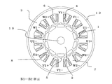
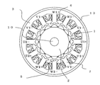
- 1, 2, 4, 4, and 5 are cross-sectional views in a plane perpendicular to the rotation axis 10 of FIG. 2, 3, 4, and 5 are cross sections taken along lines A1-A2, B1-B2, C1-C2, and D1-D2 in FIG. 1, respectively.
- the permanent magnet 1 is affixed to the surface of the rotor core 2, and the number of poles (number of magnetic poles) is 10 in this example.
- the cross-sectional shape of the permanent magnet 1 is a semi-cylindrical shape, and the torque pulsation is reduced by reducing the harmonic component of the magnetic flux and making the induced voltage sinusoidal.
- the rotor core 2 is provided with a protruding portion 8 made of the same material by a part of the rotor core 2, and serves to fix and hold the permanent magnet 1 so as not to slide in the circumferential direction.
- the stator core 3 of the stator 40 is provided with a slot 6 for winding the armature winding 4.
- the armature winding 4 is intensively wound around the teeth 7 extending in the radial direction of the stator core 3, and the number of slots is twelve. Armature windings are wound around all twelve teeth.
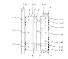
- the number of phases of the permanent magnet type rotating electrical machine is 3, and if these are the U phase, V phase, and W phase, the winding arrangement is U1 +, U1 ⁇ , V1 ⁇ , V1 +, W1 + as shown in FIG. , W1 ⁇ , U2 ⁇ , U2 +, V2 +, V2 ⁇ , W2 ⁇ , W2 +.
- + and ⁇ indicate the winding direction
- + and ⁇ indicate that the winding directions are opposite to each other.
- U1 + and U1 ⁇ are connected in series
- U2 ⁇ and U2 + are also connected in series.
- These two series circuits may be connected in parallel or may be connected in series.
- FIG. 2 is a cross section taken along line A1-A2 of FIG. 1.
- the stator core 3 is not provided with an auxiliary groove
- the rotor core 2 is provided with a protrusion 8.
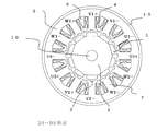
- FIG. 3 is a B1-B2 cross section of FIG. 1, in which an auxiliary groove 5 is provided in the stator core 3, and a protrusion 8 is provided in the rotor core 2.
- 4 is a cross section taken along line C1-C2 of FIG. 1.
- the stator core 3 is not provided with the auxiliary grooves 5, and the rotor core 2 is not provided with the protrusions 8.
- FIG. FIG. 5 is a cross section taken along line D1-D2 of FIG. 1, in which the auxiliary groove 5 is provided in the stator core 3, and the protrusion 8 is not provided in the rotor core 2.
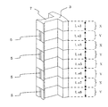
- FIG. 6 is a partial perspective view showing a stator core of the permanent magnet type rotating electric machine of FIG. FIG. 6 shows only six half of the twelve teeth to help understand the present invention.
- the stator core 3 has a tooth 7 extending in the radial direction and facing the permanent magnet, and an auxiliary groove 5 is provided on a surface facing the rotor at the tip of the tooth 7.
- the auxiliary grooves 5 are arranged at three locations in the axial direction, and the auxiliary grooves 5 near the center in the axial direction have a longer axial length than the other two auxiliary grooves 5.
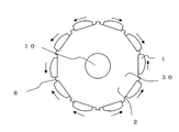
- FIG. 7 is a perspective view showing a rotor of the permanent magnet type rotating electric machine of FIG.
- the portion where the rotating shaft 10 protrudes from the end face of the rotor core 2 is omitted.
- the protective cover of the permanent magnet 1 is omitted.
- the permanent magnet 1 is provided on the surface of the rotor core 2, and a protrusion 8 is provided between adjacent permanent magnets 1.
- the protrusion part 8 is provided in the both ends of the axial direction.
- the protrusion 8 is made of a magnetic material, the configuration of the magnetic circuit in the plane cross section perpendicular to the rotation shaft 10 is different between the cross section of the portion with the protrusion 8 and the cross section of the portion without the protrusion 8. It will be.
- an object of the present invention is to provide an arrangement of the auxiliary grooves 5 that can effectively reduce the cogging torque. Yes.
- FIG. 10 is a cross-sectional view of the permanent magnet type rotating electric machine of FIG. 1, that is, the permanent magnet type rotating electric machine having the stator core of FIG. 6 and the rotor of FIG. Indicate.
- symbols A and B are used to distinguish the configuration of the magnetic circuit on the rotor 30 side.
- a region having the protrusion 8 is indicated by A, and a region having no protrusion is indicated by B.
- the protrusions 8 are provided at both ends in the axial direction, the regions A, B, and A are arranged in this order from the top in FIG.
- the lengths of these regions in the axial direction are indicated by Lr1, Lr2, and Lr3.
- an area without the auxiliary groove 5 is indicated by X
- an area with the auxiliary groove 5 is indicated by Y.
- X, Y, X, Y, X, Y, and X are arranged in this order from the top toward the paper surface.
- the lengths in the axial direction of these regions are indicated by Ls1, Ls2, Ls3, Ls4, Ls5, Ls6, and Ls7.
- the broken line in FIG. 10 is a line indicating a plane perpendicular to the axis, and is the same for FIGS. 11, 12 and 13.
- the broken lines in FIG. 10 indicate that the positions of the end face in the axial direction of the protrusion 8 and the end face in the axial direction of the auxiliary groove 5 are the same. For example, it is shown that the lower end surface of the upper protrusion 8 toward the paper surface coincides with the lower end surface of the upper auxiliary groove 5 toward the paper surface. 10, 11, 12, and 13, the same position in the axial direction on the stator side corresponding to the axial position on the rotor side is shown at the position of the broken line.
- FIG. 7 a mechanism that can significantly reduce the cogging torque when the auxiliary grooves 5 are arranged as shown in FIG.
- the ten permanent magnets 1 in the rotors of FIGS. 2 to 5 and FIG. 7 have the same sticking positions and the same sectional shape.
- manufacturing variations occur.
- the positions of the permanent magnets 1 are not evenly spaced and may deviate by several ⁇ m to 100 ⁇ m in the circumferential direction.
- the cross-sectional shape is not an ideal left-right symmetric shape, and the thickness of one of the left and right increases and the other thickness decreases. An example is shown in FIG.
- FIG. 14 shows that the position where the permanent magnet is affixed is deviated from the ideal equidistant position in the direction indicated by the arrow. Furthermore, the cross-sectional shape is not left-right symmetric, and the kamaboko-shaped apex portion moves in the direction of the arrow, indicating that it is not left-right symmetric.
- the cogging torque increases, and a component that pulsates as many times as the number of slots per one rotation of the rotor appears.
- the number of slots is 12
- FIG. 15 and 16 are diagrams showing waveforms of cogging torque corresponding to a rotation angle of 30 degrees (mechanical angle).
- the waveform indicated by AX in FIG. 15 shows that when the stator 40 and the rotor 30 of the permanent magnet type rotating electrical machine are uniformly “with protrusions and no auxiliary grooves”, the variation of the permanent magnet 1 is as shown in FIG.
- the cogging torque waveform when the state is reached is shown.
- the waveform indicated by AY shows the cogging torque when the variation of the permanent magnet 1 becomes the state shown in FIG. 14 when the stator 40 and the rotor 30 are uniformly “with protrusions and with auxiliary grooves”.
- the waveform is shown.
- the waveform shown in the legend “invention” in FIG. 15 shows that the variation of the permanent magnet 1 is the state shown in FIG. 14 when “with protrusion and without auxiliary groove” and “with protrusion and with auxiliary groove” are provided simultaneously.
- This is a waveform of the cogging torque at the time, and is an average waveform of the two waveforms.
- the component with a mechanical angle of 30 degrees is very small, and the cogging torque can be greatly reduced.
- the phase of the component having a mechanical angle of 30 degrees is reversed to cancel out the cogging torque in the portion without the auxiliary groove 5, thereby greatly reducing the cogging torque.
- FIG. 16 shows the variation of the permanent magnet 1 when the waveform indicated by BX is “no protrusion and no auxiliary groove” and the waveform indicated by BY is “no protrusion and an auxiliary groove”.
- 14 shows a cogging torque waveform when 14 state is reached.
- the waveform of the invention is provided with “no protrusion and no auxiliary groove” and “no protrusion and an auxiliary groove” at the same time, the cogging torque of the permanent magnet 1 becomes the state shown in FIG.
- the waveform is an average waveform of the two waveforms. Also in this case, it can be seen that the component of the mechanical angle of 30 degrees is very small, and the cogging torque can be greatly reduced.
- the waveform of AX in FIG. 15 is different from the waveform of BX in FIG. 16, and the waveform of AY in FIG. 15 is different from the waveform of BY in FIG. You need to be careful.
- the AX waveform and the AY waveform can be offset in the axial length Lr1 region and the Lr3 region, and the axial length Lr2 In this region, the BX waveform and the BY waveform can be canceled out, so that the cogging torque can be greatly reduced.
- the axial length in which the auxiliary groove 5 is provided is about 1/2 (for example, 1/2 ⁇ 10%), more preferably 1/2 (for example, 1/2 ⁇ 5%) of the axial length of the stator core. It is good to do.
- Ls4 Ls3 +
- Ls5 Lr2 / 2
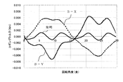
- FIG. 17 shows a comparison between the configuration of FIG. 10 and the cogging torque waveform when the auxiliary groove 5 is not provided as a conventional example.
- the conventional cogging torque is standardized with a maximum value of 100%.
- a broken line is a conventional cogging torque waveform, and a component that pulsates 12 times with one rotation of the rotor is noticeable.
- the invention of the solid line is the cogging torque waveform of the configuration of FIG.
- FIG. 18 shows a frequency analysis result of the cogging torque waveform of FIG.
- the cogging torque twelfth order component caused by the variation on the rotor 30 side can be greatly reduced as compared with the conventional example.
- FIG. 19 is a histogram of a conventional example
- FIG. 20 is a histogram of the configuration (invention) of FIG.
- the vertical axis represents the frequency
- the horizontal axis represents the magnitude of the cogging torque. Comparison is made assuming that the variation condition on the rotor 30 side is the same. In FIG. 19, the cogging torque is widely distributed, and there is a problem that the cogging torque becomes large depending on the variation pattern.
- the cogging torque is small regardless of the variation pattern of the permanent magnet 1 of the rotor 30. That is, it is possible to obtain a permanent magnet type rotating electrical machine having high robustness against manufacturing variations on the rotor 30 side.
- a reduction effect is aimed at a component in which the number of pulsations per rotation of the rotor coincides with the least common multiple of the number of poles and the number of slots, and a component generated due to variations on the rotor 30 side ( A sufficient reduction effect cannot be obtained for a component whose pulsation number matches the slot number.
- FIG. 11 can obtain the same effect as in FIG.
- FIG. 11 is an example in which the arrangement of the protrusions 8 of the rotor core 2 is the same as that of FIG. 10, but the arrangement of the auxiliary grooves 5 of the stator core 3 is different.
- the auxiliary grooves 5 in the area of Ls4 in FIG. 10 are provided in the areas of Ls3 and Ls5, and the auxiliary grooves 5 are arranged in two axial directions. Even in such an arrangement of the auxiliary grooves 5, the cogging torque reduction effect can be obtained by the mechanism described in the example of FIG.
- the axial length in which the auxiliary groove 5 is provided is about 1 ⁇ 2 (for example, 1 ⁇ 2 ⁇ 10%) of the axial length of the stator core, and more preferably 1 ⁇ 2 (for example, 1/2 ⁇ 5%) is preferable.
- Ls4 Ls3 +
- Ls5 Lr2 / 2
- FIG. 8 is a partial perspective view showing another stator core of the permanent magnet type rotating electric machine according to the first embodiment.
- FIG. 8 shows six teeth, half of the twelve, to help understanding.
- FIG. 9 is a perspective view showing another rotor of the permanent magnet type rotating electric machine according to the first embodiment.
- the portion where the rotating shaft 10 protrudes from the end face of the rotor core 2 is omitted.
- the protective cover of the permanent magnet 1 is omitted.
- the permanent magnet 1 is provided on the surface of the rotor core 2.
- a protrusion 8 made of the same material is provided at a part of the stator core 2 between the adjacent permanent magnets 1 to fix and hold the permanent magnet 1. Further, the protrusion 8 is provided at a position separated from the both ends in the axial direction by a predetermined distance.
- FIG. 12 and FIG. 13 are sectional views corresponding to this example. 12 and 13, two protrusions 8 of the rotor core are provided in the axial direction, and the positions in the axial direction are separated from the end portions by Lr1 and Lr5.
- FIG. 12 shows an example in which three auxiliary grooves 5 of the stator core 3 are arranged in the axial direction
- FIG. 13 shows an example in which two auxiliary grooves 5 are arranged in two places. If the auxiliary grooves 5 are arranged as shown in FIG. 12, the AX waveform and the AY waveform can be canceled out in the axial length Lr2 region and the Lr4 region, and the axial lengths Lr1, Lr3.
- the axial length in which the auxiliary groove 5 is provided is about 1/2 (for example, 1/2 ⁇ 10%), more preferably 1/2 (for example, 1/2 ⁇ 5%) of the axial length of the stator core. It is good to do.
- the AX waveform and the AY waveform can be offset in the axial length Lr2 region and the Lr4 region, and the axial length In the regions Lr1, Lr3, and Lr5, the BX waveform and the BY waveform can be canceled out, so that the cogging torque can be greatly reduced.
- the axial length in which the auxiliary groove 5 is provided is about 1/2 (for example, 1/2 ⁇ 10%), more preferably 1/2 (for example, 1/2 ⁇ 5%) of the axial length of the stator core. It is good to do.
- the presence or absence of the protrusion of the rotor core changes in the axial direction, but the present invention is not limited to this. If there are two or more regions in the axial direction where the magnetic circuit design of the rotor is different, such as when there is a recess instead of a protrusion between adjacent permanent magnets, or when the cross-sectional shape of the permanent magnet changes, the same The cogging torque can be greatly reduced by providing the auxiliary groove by the method.
- At least one of the cross-sectional shape in the cross section perpendicular to the rotation axis of the rotor core and the cross-sectional shape in the cross section perpendicular to the rotation axis of the permanent magnet changes in the direction of the rotation axis.
- the auxiliary groove is provided in a partial region of the stator core in the axial direction, and the region provided with the auxiliary groove is a magnetic circuit of the rotor If the design is configured to be a partial region for each region facing the same region, cogging torque (due to variations in the rotor side such as a permanent magnet sticking position error, shape error, or magnetic property variation) The component in which the number of pulsations in one rotation of the rotor matches the number of slots) can be greatly reduced.
- the above-mentioned region facing the same region of the rotor magnetic circuit design is the same region where the rotor magnetic circuit design when the rotor side and the stator side are separated by a plane perpendicular to the axis.
- the corresponding stator side area is shown.
- the region where the auxiliary groove is provided is generated in the region where the auxiliary groove is provided if the magnetic circuit design of the rotor is configured to be half the axial length of each region facing the same region.
- the effect of offsetting the cogging torque to be generated and the cogging torque generated in the region where the auxiliary groove is not provided is sufficiently exerted, and therefore, due to variations on the rotor side such as a permanent magnet sticking position error, shape error, or magnetic characteristic variation
- the generated cogging torque (a component in which the number of pulsations in one rotation of the rotor matches the number of slots) can be reduced more effectively.
- the protrusion can be used to position the permanent magnet, thereby improving the accuracy of the sticking position.
- an auxiliary groove is provided to prevent an increase in cogging torque due to a difference in magnetic circuit design caused by the protrusion, and a cogging torque generated by variations on the rotor side (the number of pulsations in one rotation of the rotor is a slot). (Components matching the number) can be more effectively reduced.
- the auxiliary groove is not provided at the axial end, so that the auxiliary groove is rotated at the axial end compared to the case where the auxiliary groove is provided at the axial end.
- the part where the gap with the child is large is reduced. This increases the effect of preventing foreign matter from entering the gap portion between the stator and the rotor.
- FIG. 21 is a diagram illustrating the auxiliary groove width Wd, auxiliary groove depth Hd, slot opening width Ws, and tooth tip thickness Hs.
- the auxiliary groove is obtained by inverting the phase of the component in which the number of pulsations of the cogging torque matches the number of slots in the portion provided with the auxiliary groove and the portion not provided with the auxiliary groove.
- the selection of the shape affects the magnitude of the effect.
- FIG. 22 is a graph in which the ratio of the width Wd of the auxiliary groove to the slot opening width Ws is plotted on the horizontal axis, and the overall value of cogging torque when variation occurs in the rotor is plotted on the vertical axis.
- the cogging torque is 1 ⁇ 2 or less that when no auxiliary groove is provided. Further, when Wd / Ws ⁇ 1.25, the cogging torque is as small as 0.001 Nm. If the cogging torque due to rotor variations is suppressed to this level, for example, when a rotating electric machine is incorporated in an electric power steering device described later, the driver does not feel the cogging torque and a good steering feeling is achieved. The effect that it can be obtained is acquired.
- the pulsation component of the permeance due to the stator core slot can be changed to reverse the phase of the component whose cogging torque pulsation number matches the slot number. Can cancel each other with cogging torque.
- Wd / Ws ⁇ 1.0 may be satisfied.
- the total width of all auxiliary grooves provided in the teeth is defined as Wd / Wd / The same effect can be obtained if Ws ⁇ 1.0.
- the depth Hd of the auxiliary groove is desirably larger than the thickness Hs of the tooth tip.
- This also changes the pulsation component of the permeance due to the slots of the stator core, and can reverse the phase of the cogging torque component whose pulsation number matches the slot number.
- the above-described canceling effect with the cogging torque in the portion without the auxiliary groove can be sufficiently exhibited.
- Patent Document 1 Patent Document 2, and Patent Document 3, an example in which two or more auxiliary grooves are provided in the circumferential direction in each tooth is described, but in Embodiment 1, the auxiliary groove is in the circumferential direction of each tooth.
- S the number of slots
- the cogging torque S-order component (S is the number of slots) generated due to variations on the rotor side is largely related to the S-order component of the permeance pulsation due to the slots of the stator, but by providing one auxiliary groove, There is an effect that it is easy to change the amplitude and phase of the S-order component of the permeance pulsation.
- the smaller the number of auxiliary grooves the smaller the average gap length. Therefore, there is only one auxiliary groove at the center in the circumferential direction and only a part in the axial direction. Limit to the limit.
- the auxiliary groove has a shape in which the iron core is cut out in a square shape, but is not limited thereto.
- the same effect can be obtained with a shape in which the iron core is cut out in an arc shape, a shape cut out in a triangular shape, or the like.
- the pole number and the least common multiple of the number of slots are 60 for the 10 poles and 12 slots and 24 for the 8 poles and 12 slots, and the cogging torque of the order of the least common multiple is 10 poles and 12 slots. small.
- the cogging torque due to the variation on the rotor side is larger than the 8-pole 12-slot and the robustness against the manufacturing variation is low.
- the problem can be solved by the first embodiment, it is possible to obtain a permanent magnet type rotating electric machine that achieves both a small and high output and a reduction in cogging torque due to manufacturing variations.
- the first embodiment can solve this problem, and it is possible to achieve both the effect of preventing the positioning of the permanent magnet and the shift in the circumferential direction and the reduction of the cogging torque S-order component.
- the cogging torque S-order component (component that pulsates S times by one rotation of the rotor) generated by variations on the rotor side, such as a permanent magnet sticking position error, shape error, or magnetic characteristic variation, is large. The problem is that the robustness against variations is low. Therefore, it is necessary to solve this problem in a permanent magnet type rotating electrical machine that is mass-produced as in an electric power steering apparatus.
- the present invention is 0.75 ⁇ S / P ⁇ 1.5.
- the robustness is high with respect to variations on the rotor side, and the cogging torque S-order component can be reduced.
- Each auxiliary tooth 5 is provided in each tooth.
- 23, 24, and 25 are cross-sectional views, but are cross-sectional views of a portion where the auxiliary groove 5 is provided, and there are portions where the auxiliary groove 5 is not provided depending on the position in the axial direction as in the first embodiment. The figure is omitted. With such a configuration, since the winding coefficient is high, it is possible to achieve both the effect of being small and having high torque and the effect of increasing robustness against variations on the rotor side.
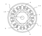
- FIG. 26 shows a magnet-embedded structure in which the permanent magnet 1 is embedded in a plurality of holes 9 (FIG. 29) provided in the rotor core 2 in the rotation axis direction.
- a rotating shaft 10 is inserted into the rotor core 2.
- a flat iron plate 1 is embedded in the rotor core 2 to form a plurality of magnetic poles.
- the rotor core 2 is provided with a recessed groove 2a in a part in the axial direction along the magnetic pole between adjacent magnetic poles on the surface portion.
- FIG. 29 shows a cross-sectional view of the portion having the recessed groove 2a.
- the permanent magnet 1 is embedded in the hole 9 of the rotor core 2, and nonmagnetic gaps 9 a are provided on the left and right sides of the permanent magnet 1. Furthermore, an iron core portion 2b between the magnetic poles is provided in the magnetic path portion of the rotor iron core 2 provided between the adjacent permanent magnets 1.
- the cross-sectional shape of the rotor core 2 in a cross section perpendicular to the rotation axis 10 changes in the axial direction as can be seen from FIG.
- the region indicated by A is provided with a recessed groove 2a
- the region indicated by B has a shape having no recessed groove.
- the cross-sectional shape changes in the order of ABAB in the axial direction, and regions with different magnetic circuit designs are arranged. Furthermore, the axial lengths of these regions are Lr1, Lr2, Lr3, and Lr4.
- FIG. 27 and FIG. 28 are partial perspective views showing only one tooth of the stator core in order to help understanding.
- the permanent magnet type rotating electrical machine of the third embodiment is a configuration example of 10 poles and 12 slots in which 12 stator cores 3 of FIG. 27 are arranged in the circumferential direction so as to surround the rotor of FIG. It is.
- the positional relationship between the rotor 30 and the stator core 3 is a positional relationship in which the axial end portions substantially coincide or coincide with each other.
- the stator core 3 of FIG. 27 in the region facing the region A where the recessed groove 2 a of the rotor core 2 is provided, the stator core 3 has a region X without the auxiliary groove 5 and a region with the auxiliary groove 5.
- Y is composed of two types of areas.
- the region facing the region B without the concave groove 2a is also composed of two types of regions, a region X without the auxiliary groove 5 and a region Y with the auxiliary groove 5.
- the axial length in which the auxiliary groove 5 is provided is about 1 ⁇ 2 (for example, 1 ⁇ 2 ⁇ 10%), more preferably 1 ⁇ 2 (for example, 1 ⁇ 2 ⁇ 5%) of the axial length of the stator core. ).
- the stator core 3 of FIG. 28 is divided into two types, a region X without the auxiliary groove 5 and a region Y with the auxiliary groove 5 in the region facing the region A where the recessed groove 2 a is provided.
- the region that is composed of the region and faces the region B without the concave groove 2 a is also composed of two types of regions, a region X without the auxiliary groove 5 and a region Y with the auxiliary groove 5.
- the axial length in which the auxiliary groove 5 is provided is about 1 ⁇ 2 (for example, 1 ⁇ 2 ⁇ 10%) of the axial length of the stator core 3, and more preferably 1 ⁇ 2 (for example, 1 ⁇ 2 ⁇ 5). %).
- Ls5 Lr4 / 2
- the cogging torque does not increase significantly even if the position of the permanent magnet shifts or the characteristics vary in the hole provided in the rotor core. That is, it is highly robust against variations on the rotor side, and the cogging torque S-order component can be reduced (S is the number of slots in the stator core).
- the shape of the hole 9 of the rotor core is designed to be large in the left-right direction of the permanent magnet, and the gap 9a is formed on the left and right of the permanent magnet when the permanent magnet is inserted, the adjacent permanent magnet Since the magnetic path portion of the rotor core provided between them, that is, the core portion 2b between the magnetic poles can be made thin, the leakage magnetic flux can be reduced, and a small high torque rotating electrical machine can be obtained.
- FIG. 30 is a perspective view of a rotor having the permanent magnet 1 provided on the surface portion of the rotor core 2 and having 10 poles. Two permanent magnets 1 are arranged in the axial direction and further provided with a stepped skew.
- the problem is solved by the following configuration.
- FIG. 30 is a partial perspective view showing only one tooth out of twelve stator cores.
- the region where the auxiliary groove 5 is not provided is X
- the region where the auxiliary groove 5 is provided is Y
- the regions are arranged in the order XYXY.
- Each axial length is Ls1, Ls2, Ls3, Ls4.
- both the presence and absence of the auxiliary groove 5 are provided in each of the regions M1 and M2.
- the structure With such a structure, the canceling effect of M1-X and M1-Y and the canceling effect of M2-X and M2-Y are sufficiently exhibited, and the permanent magnets are arranged between the permanent magnets arranged in the rotation axis direction.
- the cogging torque S-order component can be reduced even when the variation in shape, the error in the pasting position, or the variation in magnetic characteristics changes greatly between two or more permanent magnets arranged in the axial direction (S is the stator). Number of slots in the iron core).
- the axial length in which the auxiliary groove is provided is about 1 ⁇ 2 (for example, 1 ⁇ 2 ⁇ 10%), more preferably 1 ⁇ 2 (for example, 1 ⁇ 2 ⁇ 5%) of the axial length of the stator core. It is good.
- the permanent magnet 1 is an example of a segment magnet, but the present invention is not limited to this.
- FIG. 32 shows an example in which two ring-shaped magnets are arranged in the axial direction. Ring-shaped permanent magnets include those with radial anisotropy, polar anisotropy, and no anisotropy, but the S-order component of cogging torque (S is the stator core due to variations in orientation and magnetization) Number of slots) may occur.
- S is the stator core due to variations in orientation and magnetization
- Number of slots Number of slots
- an auxiliary groove is arranged as in the stator iron core of FIG. 31, a configuration that can more effectively reduce the cogging torque is obtained.
- an example in which two are arranged in the axial direction is shown, but it goes without saying that the same effect can be obtained even in the case of three or more.
- a region in which the auxiliary groove is not provided is X
- a region in which the auxiliary groove is provided is Y
- the same arrangement is obtained in the order of XYYX.
- a cogging torque S-order component (a component that pulsates S times by one rotation of the rotor) generated by variations on the rotor side such as a permanent magnet sticking position error, shape error, or magnetic characteristic variation is large, and the rotor side The problem is that the robustness against variations is low.
- the fourth embodiment is changed to 0.75 ⁇ S / P ⁇ 1.5.
- the robustness is high with respect to variations on the rotor side, and the cogging torque S-order component can be reduced.
- the auxiliary groove is provided at one central portion in the circumferential direction of the teeth of the stator core, an effect that the torque is reduced less than the conventional example can be obtained. Therefore, it is possible to achieve both compact realization of high torque and high robustness, and to obtain a special effect that cannot be obtained in Patent Document 1, Patent Document 2, and Patent Document 3 by the configuration of the fourth embodiment. Can do.
- FIG. 33 is a conceptual diagram showing an electric power steering device for a vehicle using the permanent magnet type rotating electric machine according to the first to fourth embodiments.
- the electric power steering apparatus is provided with a column shaft 23 for transmitting a steering force from the steering wheel 22.
- the column shaft 23 is connected to a worm gear 24 (details are omitted in the figure and only a gear box is shown).
- the worm gear 24 transmits the output (torque, rotation speed) of the drive motor 20 controlled by the controller 21 while changing the rotation direction to a right angle, and simultaneously decelerates to increase the assist torque.
- Reference numeral 25 denotes a handle joint which transmits a steering force and also changes the rotation direction.
- Reference numeral 26 denotes a steering gear (details are omitted in the figure, only the gear box is shown), and the rotation of the column shaft 23 is decelerated and simultaneously converted into a linear motion of the rack 27 to obtain a required displacement. The wheels are moved by the linear motion of the rack 27, and the direction of the vehicle can be changed.
- the pulsation of torque generated by the drive motor 20 is transmitted to the steering wheel 22 via the worm gear 24 and the column shaft 23. Therefore, when the drive motor 20 generates a large torque pulsation, a smooth steering feeling cannot be obtained.
- the torque pulsation can be reduced by incorporating the permanent magnet type rotating electric machine of the first to fourth embodiments as the drive motor 20 of the electric power steering apparatus of the fifth embodiment. For this reason, the steering feeling in the electric power steering apparatus can be improved.
Abstract
Description
この発明は、前記のような問題点を解決するためになされたものであり、コギングトルクを低減した永久磁石型回転電機及びそれを用いた電動パワーステアリング装置を得ることを目的としている。 In the permanent magnet type rotating electrical machine of
The present invention has been made to solve the above-described problems, and an object of the present invention is to obtain a permanent magnet type rotating electric machine with reduced cogging torque and an electric power steering device using the same.
この発明の前記以外の目的、特徴、観点及び効果は、図面を参照する以下のこの発明の詳細な説明から、さらに明らかになるであろう。 In the permanent magnet type rotating electrical machine according to the present invention, the cogging torque (the number of pulsations per one rotation of the rotor matches the number of slots) generated by variations on the rotor side such as a permanent magnet sticking position error, shape error, or variation in magnetic characteristics. Component).
Other objects, features, aspects and advantages of the present invention will become more apparent from the following detailed description of the present invention with reference to the drawings.
図1はこの発明の実施の形態1の永久磁石型回転電機について、回転軸に平行かつ回転軸を通る平面上の模式的な断面図を示す。回転子鉄心2の表面に永久磁石1が備え付けられている。永久磁石1の周方向端部付近に突起部8が設けられ、突起部8は永久磁石1を挟み込むような配置となっている。突起部8が隣合う永久磁石1の間に配置される場合、回転軸(シャフト)10に平行かつ回転軸10を通る平面上の断面図には、突起部8と永久磁石1が同時に描かれることはないが、図1は理解を助けるために同時に描いている。
1 is a schematic cross-sectional view on a plane that is parallel to and passes through a rotation axis of the permanent magnet type rotating electric machine according to
Ls1=Ls2=Lr1/2
Ls4=Ls3+Ls5=Lr2/2
Ls6=Ls7=Lr3/2
とすれば、A-Xの領域とA-Yの領域の軸方向長さが等しくなり、さらにB-Xの領域とB-Yの領域の軸方向長さが等しくなるため、コギングトルク低減効果をより発揮できる構成となる。 Furthermore, in FIG. 10, Ls1 = Ls2 = Lr1 / 2
Ls4 = Ls3 + Ls5 = Lr2 / 2
Ls6 = Ls7 = Lr3 / 2
If this is the case, the axial lengths of the AX region and the AY region are equal, and the axial lengths of the BX region and BY region are equal. It becomes the structure which can demonstrate more.
Ls1=Ls2=Lr1/2
Ls4=Ls3+Ls5=Lr2/2
Ls6=Ls7=Lr3/2
とすれば、A-Xの領域とA-Yの領域の軸方向長さが等しくなり、さらにB-Xの領域とB-Yの領域の軸方向長さが等しくなるため、コギングトルク低減効果をより発揮できる構成となることは言うまでもない。 Furthermore, in FIG. 11, Ls1 = Ls2 = Lr1 / 2
Ls4 = Ls3 + Ls5 = Lr2 / 2
Ls6 = Ls7 = Lr3 / 2
If this is the case, the axial lengths of the AX region and the AY region are equal, and the axial lengths of the BX region and BY region are equal. Needless to say, the configuration is such that the above can be further demonstrated.
Ls1=Ls2=Lr1/2
Ls3=Ls4=Lr2/2
Ls5+Ls7=Ls6=Lr3/2
Ls8=Ls9=Lr4/2
Ls10=Ls11=Lr5/2
とすれば、A-Xの領域とA-Yの領域の軸方向長さが等しくなり、さらにB-Xの領域とB-Yの領域の軸方向長さが等しくなるため、コギングトルク低減効果をより発揮できる構成となる。 Furthermore, in FIG. 12, Ls1 = Ls2 = Lr1 / 2
Ls3 = Ls4 = Lr2 / 2
Ls5 + Ls7 = Ls6 = Lr3 / 2
Ls8 = Ls9 = Lr4 / 2
Ls10 = Ls11 = Lr5 / 2
If this is the case, the axial lengths of the AX region and the AY region are equal, and the axial lengths of the BX region and BY region are equal. It becomes the structure which can demonstrate more.
Ls1=Lr1
Ls2=Ls3=Lr2/2
Ls7=Ls8=Lr4/2
Ls4+Ls6=Ls1+Ls5+Ls9=(Lr1+Lr3+Lr5)/2
Ls9=Lr5
とすれば、A-Xの領域とA-Yの領域の軸方向長さが等しくなり、さらにB-Xの領域とB-Yの領域の軸方向長さが等しくなるため、コギングトルク低減効果をより発揮できる構成となる。 Furthermore, in FIG. 13, Ls1 = Lr1
Ls2 = Ls3 = Lr2 / 2
Ls7 = Ls8 = Lr4 / 2
Ls4 + Ls6 = Ls1 + Ls5 + Ls9 = (Lr1 + Lr3 + Lr5) / 2
Ls9 = Lr5
If this is the case, the axial lengths of the AX region and the AY region are equal, and the axial lengths of the BX region and BY region are equal. It becomes the structure which can demonstrate more.
さらに、補助溝の深さHdはティース先端部の厚みHsよりも大きいことが望ましい。これも固定子鉄心のスロットによるパーミアンスの脈動成分を変化させ、脈動数がスロット数と一致するコギングトルクの成分の位相を反転させることができる。上述した補助溝のない部分でのコギングトルクとのキャンセル効果を十分に発揮することができる。 When Wd / Ws ≧ 1.0, the pulsation component of the permeance due to the stator core slot can be changed to reverse the phase of the component whose cogging torque pulsation number matches the slot number. Can cancel each other with cogging torque. When one auxiliary groove is provided, Wd / Ws ≧ 1.0 may be satisfied. When two or more auxiliary grooves are provided, the total width of all auxiliary grooves provided in the teeth is defined as Wd / Wd / The same effect can be obtained if Ws ≧ 1.0.
Further, the depth Hd of the auxiliary groove is desirably larger than the thickness Hs of the tooth tip. This also changes the pulsation component of the permeance due to the slots of the stator core, and can reverse the phase of the cogging torque component whose pulsation number matches the slot number. The above-described canceling effect with the cogging torque in the portion without the auxiliary groove can be sufficiently exhibited.
実施の形態1では、極数(磁極数)10、スロット数12の例について述べたが、この発明はそれに限らない。永久磁石型回転電機の極数をP、スロット数をSとすると、
0.75<S/P<1.5
なる関係がある組み合わせの場合、特許文献1,特許文献2,特許文献3で述べられているS/P=0.75,S/P=1.5の場合に比べて、巻線係数が高く永久磁石の磁束を効率的に利用し小型で高トルクの永久磁石型回転電機が得られることが知られている。
In the first embodiment, the example of the number of poles (number of magnetic poles) 10 and the number of
0.75 <S / P <1.5
In the case of the combination having the relationship, the winding coefficient is higher than in the case of S / P = 0.75 and S / P = 1.5 described in
0.75<S/P<1.5
なる関係がある組み合わせの永久磁石型回転電機に適用すると、回転子側のばらつきに対してロバスト性が高く、コギングトルクS次成分を小さくすることができる。
0.75<S/P<1.5
を満たす永久磁石型回転電機のうち、図23にはP=14,S=12の例、図24にはP=8,S=9の例、図25にはP=10,S=9を示した。 Therefore, the present invention is 0.75 <S / P <1.5.
When applied to a combination of permanent magnet type rotating electrical machines having such a relationship, the robustness is high with respect to variations on the rotor side, and the cogging torque S-order component can be reduced.
0.75 <S / P <1.5
FIG. 23 shows an example of P = 14, S = 12, FIG. 24 shows an example of P = 8, S = 9, and FIG. 25 shows P = 10, S = 9. Indicated.
nを自然数とし、
極数P=12n±2n,スロット数S=12n
極数P=9n±n,スロット数S=9n
であれば同じ効果が得られる。 In addition, since the same effect can be obtained by a combination of the number of poles and an integral multiple of the number of slots, generalization including the number of poles P = 10 and the number of slots S = 12,
Let n be a natural number,
Number of poles P = 12n ± 2n, number of slots S = 12n
Number of poles P = 9n ± n, number of slots S = 9n
If so, the same effect can be obtained.
これまでの実施の形態では永久磁石が回転子鉄心の表面に設けられた表面磁石型の例であったが、この発明はこれに限らず適用できる。図26には永久磁石1が回転子鉄心2内部に設けられた回転軸方向の複数の孔部9(図29)に埋め込まれた磁石埋め込み型構造である。回転子鉄心2に回転軸10が挿入されている。回転子鉄心2には平板状の永久磁石1が埋め込まれ複数の磁極が構成となっている。さらに回転子鉄心2には表面部で隣合う磁極間に磁極に沿って、軸方向の一部に凹部溝2aが設けられている。凹部溝2aがある部分の断面図を図29に示す。回転子鉄心2の孔部9に永久磁石1が埋め込まれ、永久磁石1の左右には非磁性の空隙部9aが設けられている。さらに、隣合う永久磁石1間に設けられた回転子鉄心2の磁路部分には磁極間の鉄心部2bが設けられている。
In the above embodiments, the permanent magnet is an example of the surface magnet type provided on the surface of the rotor core, but the present invention is not limited to this and can be applied. FIG. 26 shows a magnet-embedded structure in which the
Ls1=Ls2=Lr1/2
Ls3=Ls4=Lr2/2
Ls5=Ls6=Ls3/2
Ls7=Ls8=Lr4/2
とすれば、実施の形態1で述べたようにA-Xの領域とA-Yの領域の軸方向長さが等しくなり、さらにB-Xの領域とB-Yの領域の軸方向長さが等しくなるため、コギングトルク低減効果をより発揮できる構成となる。 Furthermore, in FIGS.
Ls1 = Ls2 = Lr1 / 2
Ls3 = Ls4 = Lr2 / 2
Ls5 = Ls6 = Ls3 / 2
Ls7 = Ls8 = Lr4 / 2
As described in the first embodiment, the axial lengths of the AX region and the AY region are equal, and the axial lengths of the BX region and the BY region are equal. Therefore, the cogging torque reduction effect can be further exhibited.
Ls1=Ls2/2=Lr1/2
Ls2/2=Ls3/2=Lr2/2
Ls3/2=Ls4/2=Lr3/2
Ls4/2=Ls5=Lr4/2
とすればA-Xの領域とA-Yの領域の軸方向長さが等しくなり、さらにB-Xの領域とB-Yの領域の軸方向長さが等しくなるため、コギングトルク低減効果をより発揮できる構成となる。 Further, in FIGS.
Ls1 = Ls2 / 2 = Lr1 / 2
Ls2 / 2 = Ls3 / 2 = Lr2 / 2
Ls3 / 2 = Ls4 / 2 = Lr3 / 2
Ls4 / 2 = Ls5 = Lr4 / 2
Then, the axial lengths of the AX region and the AY region are equal, and the axial lengths of the BX region and the BY region are equal, which reduces the cogging torque reduction effect. It becomes the structure which can be exhibited more.
実施の形態1~3では、回転子鉄心の回転軸に垂直な断面における断面形状と永久磁石の回転軸に垂直な断面における断面形状のうち少なくとも一方が回転軸方向で変化することによって、磁気回路設計が異なる領域を回転軸方向に2つ以上有する構成の永久磁石型回転電機について述べたが、ここでは別の構成例を述べる。図30は、回転子鉄心2の表面部に永久磁石1を設け、極数が10の回転子の斜視図である。永久磁石1は軸方向に2つ並べられ、さらに階段状のスキューを設けている。
In the first to third embodiments, at least one of the cross-sectional shape in the cross section perpendicular to the rotation axis of the rotor core and the cross-sectional shape in the cross section perpendicular to the rotation axis of the permanent magnet changes in the direction of the rotation axis. Although the permanent magnet type rotating electrical machine having two or more regions having different designs in the rotation axis direction has been described, another configuration example will be described here. FIG. 30 is a perspective view of a rotor having the
Ls1=Ls2=Lr1/2
Ls3=Ls4=Lr2/2
とすればM1-Xの領域とM1-Yの領域の軸方向長さが等しくなり、さらにM2-Xの領域とM2-Yの領域の軸方向長さが等しくなるため、コギングトルク低減効果をより発揮できる構成となる。 Further, in FIGS.
Ls1 = Ls2 = Lr1 / 2
Ls3 = Ls4 = Lr2 / 2
Then, the axial lengths of the M1-X region and the M1-Y region are equal, and the axial lengths of the M2-X region and the M2-Y region are equal. It becomes the structure which can be exhibited more.
0.75<S/P<1.5
なる関係がある組み合わせの場合、特許文献1,特許文献2,特許文献3で述べられているS/P=0.75,S/P=1.5の場合に比べて、巻線係数が高く、永久磁石の磁束を効率的に利用し、小型で高トルクの永久磁石型回転電機が得られることが知られている。 30 and FIG. 31, the example of the number of poles (number of magnetic poles) 10 and the number of
0.75 <S / P <1.5
In the case of the combination having the relationship, the winding coefficient is higher than in the case of S / P = 0.75 and S / P = 1.5 described in
0.75<S/P<1.5
なる関係がある組み合わせの永久磁石型回転電機に適用すると、回転子側のばらつきに対してロバスト性が高く、コギングトルクS次成分を小さくすることができる。
また,図31では補助溝が固定子鉄心のティースの周方向中央部に1箇所設けられているので,従来例よりトルクの低下が少ないという効果が得られる。したがって、小型で高トルクの実現とロバスト性を高くすることの両立が可能となり、実施の形態4の構成により,特許文献1,特許文献2,特許文献3では得られない格別の効果を得ることができる。 Further, since the least common multiple of the number of poles and the number of slots is large, the cogging torque component that pulsates the number of times that matches the least common multiple of the number of poles and the number of slots in one rotation of the rotor is S / P = 0.75, S / P It is also known that it is smaller than the case of = 1.5. On the other hand, a cogging torque S-order component (a component that pulsates S times by one rotation of the rotor) generated by variations on the rotor side such as a permanent magnet sticking position error, shape error, or magnetic characteristic variation is large, and the rotor side The problem is that the robustness against variations is low. Therefore, it is necessary to solve this problem in a permanent magnet type rotating electrical machine that is mass-produced as in the case of being mounted on an electric power steering device. Therefore, the fourth embodiment is changed to 0.75 <S / P <1.5.
When applied to a combination of permanent magnet type rotating electrical machines having such a relationship, the robustness is high with respect to variations on the rotor side, and the cogging torque S-order component can be reduced.
Moreover, in FIG. 31, since the auxiliary groove is provided at one central portion in the circumferential direction of the teeth of the stator core, an effect that the torque is reduced less than the conventional example can be obtained. Therefore, it is possible to achieve both compact realization of high torque and high robustness, and to obtain a special effect that cannot be obtained in
図33は、実施の形態1~4の永久磁石型回転電機を用いた車両用の電動パワーステアリング装置を示す概念図である。図33において、電動パワーステアリング装置には、ステアリングホイール22から操舵力を伝えるためのコラムシャフト23が設けられている。コラムシャフト23にはウォームギヤ24(図では詳細は省略し、ギヤボックスのみ示している)が接続されている。ウォームギヤ24はコントローラ21によって制御される駆動モータ20の出力(トルク、回転数)を、回転方向を直角に変えながら伝達し、同時に減速し、アシストトルクを増加させる。25はハンドルジョイントであり、操舵力を伝えると共に、回転方向も変える。26はステアリングギヤ(図では詳細は省略し、ギヤボックスのみ示している)であり、コラムシャフト23の回転を減速し、同時にラック27の直線運動に変換し、所要の変位を得る。このラック27の直線運動により車輪を動かし、車両の方向転換等を可能とする。
FIG. 33 is a conceptual diagram showing an electric power steering device for a vehicle using the permanent magnet type rotating electric machine according to the first to fourth embodiments. In FIG. 33, the electric power steering apparatus is provided with a
この発明の各種の変形または変更は、関連する熟練技術者が、この発明の範囲と精神を逸脱しない中で実現可能であり、この明細書に記載された各実施の形態には制限されないことと理解されるべきである。 Further, since the drive motor for the electric power steering apparatus is mass-produced, there is a problem that the robustness of the cogging torque with respect to manufacturing variations must be improved. On the other hand, by installing the permanent magnet type rotating electrical machine described in the first to fourth embodiments, the cogging torque component caused by the variation of the rotor can be greatly reduced, and thus the robustness is improved. .
Various modifications or alterations of the present invention can be realized without departing from the scope and spirit of the present invention by a related expert, and are not limited to the embodiments described in this specification. Should be understood.
Claims (15)
- 永久磁石により構成された複数の磁極と回転子鉄心を有する回転子、
電機子巻線と、前記電機子巻線を収めるスロットが設けられ、前記回転子と対向する複数のティースを有する固定子鉄心とを具備する固定子を備え、
前記固定子鉄心の前記ティースの前記回転子に対向する部分に補助溝が設けられる永久磁石型回転電機において、
前記永久磁石と前記回転子鉄心を有する前記回転子の回転軸に垂直な断面における断面形状が回転軸方向で変化することによる、磁気回路設計が異なる領域が前記回転子の回転軸方向に2つ以上設けられ、
前記補助溝は前記固定子鉄心の前記ティースの軸方向の一部の領域に設けられており、
前記補助溝が設けられている領域は、前記回転子の磁気回路設計が同じ領域に対向する領域毎にそれぞれその一部の領域であることを特徴とする永久磁石型回転電機。 A rotor having a plurality of magnetic poles constituted by permanent magnets and a rotor core;
A stator comprising an armature winding and a stator core provided with a slot for accommodating the armature winding and having a plurality of teeth facing the rotor;
In the permanent magnet type rotating electrical machine in which an auxiliary groove is provided in a part of the stator core facing the rotor of the teeth,
There are two regions with different magnetic circuit designs in the direction of the rotation axis of the rotor because the cross-sectional shape in the cross section perpendicular to the rotation axis of the rotor having the permanent magnet and the rotor core changes in the direction of the rotation axis. Provided
The auxiliary groove is provided in a partial region in the axial direction of the teeth of the stator core,
The area provided with the auxiliary groove is a partial area for each area facing the same area of the rotor magnetic circuit design. - 前記補助溝が設けられている領域は、前記回転子の磁気回路設計が同じ領域に対向する領域毎にそれぞれその軸方向長さの半分の領域であることを特徴とする請求項1記載の永久磁石型回転電機。 2. The permanent region according to claim 1, wherein the region in which the auxiliary groove is provided is a region that is half the axial length of each region facing the same region of the rotor magnetic circuit design. Magnet type rotating electrical machine.
- 前記回転子鉄心の回転軸方向の一部に、前記永久磁石を保持する突起部が設けられ、
前記補助溝は前記固定子鉄心の前記ティースの軸方向の一部の領域に設けられており、
前記補助溝が設けられている領域は、
前記突起部が設けられた領域と、前記突起部が設けられていない領域とに、対向する領域毎にそれぞれその一部の領域であることを特徴とする請求項1記載の永久磁石型回転電機。 Protrusions for holding the permanent magnets are provided on a part of the rotor core in the rotation axis direction,
The auxiliary groove is provided in a partial region in the axial direction of the teeth of the stator core,
The region where the auxiliary groove is provided is
The permanent magnet type rotating electric machine according to claim 1, wherein the region where the protrusion is provided and the region where the protrusion is not provided are a part of each region facing each other. . - 前記回転子鉄心の回転軸方向の一部に、前記永久磁石を保持する突起部が設けられ、
前記補助溝は前記固定子鉄心の前記ティースの軸方向の一部の領域に設けられており、
前記補助溝が設けられている領域は、
前記突起部が設けられた領域と、前記前記突起部が設けられていない領域とに、対向する領域毎にそれぞれその軸方向長さの半分の領域であることを特徴とする請求項2記載の永久磁石型回転電機。 Protrusions for holding the permanent magnets are provided on a part of the rotor core in the rotation axis direction,
The auxiliary groove is provided in a partial region in the axial direction of the teeth of the stator core,
The region where the auxiliary groove is provided is
The region where the protrusion is provided and the region where the protrusion is not provided are regions that are half the axial length of each of the opposing regions. Permanent magnet type rotating electric machine. - 前記補助溝の幅Wdは、前記スロットの開口幅Wsよりも大きいことを特徴とする請求項1~請求項4のいずれか1項に記載の永久磁石型回転電機。 The permanent magnet type rotating electric machine according to any one of claims 1 to 4, wherein a width Wd of the auxiliary groove is larger than an opening width Ws of the slot.
- 前記補助溝の深さHdが前記ティースの先端部の厚みHsよりも大きいことを特徴とする請求項1~請求項4のいずれか1項に記載の永久磁石型回転電機。 The permanent magnet type rotating electric machine according to any one of claims 1 to 4, wherein a depth Hd of the auxiliary groove is larger than a thickness Hs of a tip portion of the tooth.
- 前記補助溝は、前記固定子鉄心の軸方向端部には設けられていないことを特徴とする請求項1~請求項4のいずれか1項に記載の永久磁石型回転電機。 The permanent magnet type rotating electric machine according to any one of claims 1 to 4, wherein the auxiliary groove is not provided at an axial end of the stator core.
- 前記補助溝は前記ティースの前記回転子に対向する部分において、前記固定子鉄心の周方向中央部に1箇所設けられていることを特徴とする請求項1~請求項4のいずれか1項に記載の永久磁石型回転電機。 The auxiliary groove according to any one of claims 1 to 4, wherein the auxiliary groove is provided at one place in a circumferential central portion of the stator core at a portion of the teeth facing the rotor. The permanent magnet type rotating electric machine described.
- 前記回転子の前記磁極の極数をP、前記固定子の前記スロットの数をSとしたとき、
0.75<S/P<1.5
なる関係が成り立つようにした請求項1~請求項4のいずれか1項に記載の永久磁石型回転電機。 When the number of poles of the magnetic pole of the rotor is P and the number of slots of the stator is S,
0.75 <S / P <1.5
The permanent magnet type rotating electric machine according to any one of claims 1 to 4, wherein the following relationship is established. - nを自然数とし、前記回転子の前記磁極の極数Pが12n±2n、前記固定子の前記スロットの数Sが12nであることを特徴とする請求項1~請求項4のいずれか1項に記載の永久磁石型回転電機。 5. The method according to claim 1, wherein n is a natural number, the number P of the magnetic poles of the rotor is 12n ± 2n, and the number S of the slots of the stator is 12n. The permanent magnet type rotating electrical machine described in 1.
- nを自然数とし、前記回転子の前記磁極の極数Pが9n±n、前記固定子の前記スロット数Sが9nであることを特徴とする請求項1~請求項4のいずれか1項に記載の永久磁石型回転電機。 5. The method according to claim 1, wherein n is a natural number, the pole number P of the magnetic pole of the rotor is 9n ± n, and the slot number S of the stator is 9n. The permanent magnet type rotating electric machine described.
- 前記回転子には、前記回転子鉄心に設けられた回転軸方向の複数の孔部に前記永久磁石を埋め込んで複数の磁極が構成され、
前記回転子鉄心には、その表面部で隣合う前記磁極間に前記磁極に沿って、軸方向の一部に凹部溝が形成されたことを特徴とする請求項1又は請求項2記載の永久磁石型回転電機。 In the rotor, a plurality of magnetic poles are configured by embedding the permanent magnets in a plurality of holes in a rotation axis direction provided in the rotor core,
3. The permanent magnet according to claim 1, wherein a concave groove is formed in a part of the rotor core in the axial direction along the magnetic pole between the magnetic poles adjacent to each other on a surface portion thereof. Magnet type rotating electrical machine. - 永久磁石により構成された複数の磁極と回転子鉄心を有する回転子、
電機子巻線と、前記電機子巻線を収めるスロットが設けられ、前記回転子と対向する複数のティースを有する固定子鉄心とを具備する固定子を備え、
前記固定子鉄心の前記ティースの前記回転子に対向する部分に補助溝が設けられる永久磁石型回転電機において、
前記回転子の複数の前記磁極はそれぞれ回転軸方向に2つ以上の永久磁石を並べて構成されており、
前記補助溝は前記固定子鉄心の前記ティースの軸方向の一部の領域に設けられており、
前記補助溝が設けられている領域は、回転軸方向に2つ以上配置された前記永久磁石に対向する領域毎にそれぞれその一部の領域であることを特徴とする永久磁石型回転電機。 A rotor having a plurality of magnetic poles constituted by permanent magnets and a rotor core;
A stator comprising an armature winding and a stator core provided with a slot for accommodating the armature winding and having a plurality of teeth facing the rotor;
In the permanent magnet type rotating electrical machine in which an auxiliary groove is provided in a part of the stator core facing the rotor of the teeth,
Each of the plurality of magnetic poles of the rotor is configured by arranging two or more permanent magnets in the rotation axis direction,
The auxiliary groove is provided in a partial region in the axial direction of the teeth of the stator core,
The area where the auxiliary groove is provided is a partial area for each of the areas facing the permanent magnets arranged at least two in the rotation axis direction. - 前記補助溝が設けられている領域は、回転軸方向に2つ以上配置された前記永久磁石に対向する領域毎にそれぞれその軸方向長さの半分の領域であることを特徴とする請求項13記載の永久磁石型回転電機。 14. The region where the auxiliary grooves are provided is a region that is half of the axial length for each region that faces the permanent magnets that are arranged two or more in the rotational axis direction. The permanent magnet type rotating electric machine described.
- 請求項1~請求項14のいずれか1項に記載の永久磁石型回転電機を駆動モータとして使用することを特徴とする電動パワーステアリング装置。 An electric power steering apparatus using the permanent magnet type rotating electric machine according to any one of claims 1 to 14 as a drive motor.
Priority Applications (6)
| Application Number | Priority Date | Filing Date | Title |
|---|---|---|---|
| CN201080068416.7A CN103053094B (en) | 2010-09-06 | 2010-09-06 | Permanent-magnet type electric rotating machine and utilize the driven steering device of this permanent-magnet type electric rotating machine |
| JP2012532746A JP5645940B2 (en) | 2010-09-06 | 2010-09-06 | Permanent magnet type rotating electric machine and electric power steering apparatus using the same |
| EP10856941.9A EP2615721B1 (en) | 2010-09-06 | 2010-09-06 | Permanent magnet type rotating electrical machine and electrical power steering device using same |
| PCT/JP2010/065228 WO2012032591A1 (en) | 2010-09-06 | 2010-09-06 | Permanent magnet type rotating electrical machine and electrical power steering device using same |
| US13/697,064 US9172278B2 (en) | 2010-09-06 | 2010-09-06 | Permanent magnet type rotary electric machine and electric power steering apparatus using the same |
| US14/724,848 US20150263571A1 (en) | 2010-09-06 | 2015-05-29 | Permanent magnet type rotary electric machine and electric power steering apparatus using the same |
Applications Claiming Priority (1)
| Application Number | Priority Date | Filing Date | Title |
|---|---|---|---|
| PCT/JP2010/065228 WO2012032591A1 (en) | 2010-09-06 | 2010-09-06 | Permanent magnet type rotating electrical machine and electrical power steering device using same |
Related Child Applications (2)
| Application Number | Title | Priority Date | Filing Date |
|---|---|---|---|
| US13/697,064 A-371-Of-International US9172278B2 (en) | 2010-09-06 | 2010-09-06 | Permanent magnet type rotary electric machine and electric power steering apparatus using the same |
| US14/724,848 Division US20150263571A1 (en) | 2010-09-06 | 2015-05-29 | Permanent magnet type rotary electric machine and electric power steering apparatus using the same |
Publications (1)
| Publication Number | Publication Date |
|---|---|
| WO2012032591A1 true WO2012032591A1 (en) | 2012-03-15 |
Family
ID=45810217
Family Applications (1)
| Application Number | Title | Priority Date | Filing Date |
|---|---|---|---|
| PCT/JP2010/065228 WO2012032591A1 (en) | 2010-09-06 | 2010-09-06 | Permanent magnet type rotating electrical machine and electrical power steering device using same |
Country Status (5)
| Country | Link |
|---|---|
| US (2) | US9172278B2 (en) |
| EP (1) | EP2615721B1 (en) |
| JP (1) | JP5645940B2 (en) |
| CN (1) | CN103053094B (en) |
| WO (1) | WO2012032591A1 (en) |
Cited By (6)
| Publication number | Priority date | Publication date | Assignee | Title |
|---|---|---|---|---|
| JP2017108565A (en) * | 2015-12-10 | 2017-06-15 | 日立オートモティブシステムズエンジニアリング株式会社 | Rotary electric machine |
| JP6309178B1 (en) * | 2017-04-05 | 2018-04-11 | 三菱電機株式会社 | Stator core piece and rotating electric machine |
| JP2019500223A (en) * | 2015-10-05 | 2019-01-10 | マルティン ツィマーMartin Zimmer | Gripping device with integrated controller |
| WO2022091198A1 (en) * | 2020-10-27 | 2022-05-05 | 三菱電機株式会社 | Rotary electric machine and electric power steering device |
| WO2023018121A1 (en) * | 2021-08-09 | 2023-02-16 | 엘지이노텍 주식회사 | Motor |
| JP7475482B2 (en) | 2020-10-27 | 2024-04-26 | 三菱電機株式会社 | Rotating electric machine and electric power steering device |
Families Citing this family (17)
| Publication number | Priority date | Publication date | Assignee | Title |
|---|---|---|---|---|
| US9325229B2 (en) * | 2013-03-15 | 2016-04-26 | Hamilton Sundstrand Corporation | Generator architecture with PMG exciter and main field rotating power converter |
| DE112013006948B4 (en) * | 2013-04-15 | 2021-09-30 | Mitsubishi Electric Corporation | Rotor of a lathe |
| CN103312068B (en) * | 2013-06-07 | 2016-03-23 | 芜湖微特电机有限公司 | A kind of energy-saving servo motor |
| EP2897265A1 (en) | 2014-01-15 | 2015-07-22 | Siemens Aktiengesellschaft | Rotor with a assembly of permanent magnets arranged in axial direction and electric machine comprising such a rotor |
| JP5808445B2 (en) * | 2014-02-21 | 2015-11-10 | ファナック株式会社 | Rotor for electric motor including magnet attached to outer peripheral surface of rotor core, electric motor, and method for manufacturing electric motor rotor |
| DE102014212869A1 (en) * | 2014-07-03 | 2016-01-07 | Schaeffler Technologies AG & Co. KG | Dynamoelectric machine with sliding flux guides |
| DE102014212872A1 (en) * | 2014-07-03 | 2016-01-07 | Schaeffler Technologies AG & Co. KG | Electric machine with mechanical field weakening and fail-safe actuator |
| JP6411833B2 (en) * | 2014-09-22 | 2018-10-24 | 株式会社ミツバ | Brushless motor |
| EP3322071A1 (en) * | 2015-02-18 | 2018-05-16 | Nidec Motor Corporation | Electric motor |
| JP6592525B2 (en) | 2015-10-30 | 2019-10-16 | 日立オートモティブシステムズ株式会社 | Magnet rotor, rotating electric machine including magnet rotor, and electric vehicle including rotating electric machine |
| JP6430570B2 (en) * | 2017-03-27 | 2018-11-28 | 岡山県 | In-wheel motor |
| CN109510330A (en) * | 2017-09-15 | 2019-03-22 | 台达电子工业股份有限公司 | Direct-flow brushless motor fan and preparation method thereof |
| JP2020043695A (en) * | 2018-09-11 | 2020-03-19 | 株式会社日立製作所 | Rotary electric machine, and hoist system for elevator |
| CN109120080A (en) * | 2018-09-19 | 2019-01-01 | 珠海格力电器股份有限公司 | Motor stator, motor and bus |
| US11031853B2 (en) * | 2019-05-23 | 2021-06-08 | Mando Corporation | Variable air gap along axial direction for reducing cogging torque in permanent magnet motors |
| KR20210012707A (en) * | 2019-07-26 | 2021-02-03 | 엘지이노텍 주식회사 | Motor |
| CN114614611B (en) * | 2021-12-14 | 2023-09-08 | 苏州长风航空电子有限公司 | Angular displacement sensor sensitive assembly |
Citations (10)
| Publication number | Priority date | Publication date | Assignee | Title |
|---|---|---|---|---|
| JPS5032502U (en) * | 1973-07-17 | 1975-04-09 | ||
| JP2001025182A (en) | 1999-07-02 | 2001-01-26 | Matsushita Electric Ind Co Ltd | Permanent magnet motor |
| JP2001145319A (en) * | 1999-11-12 | 2001-05-25 | Matsushita Electric Ind Co Ltd | Motor |
| JP2004153913A (en) * | 2002-10-30 | 2004-05-27 | Fuji Electric Fa Components & Systems Co Ltd | Rotor for permanent magnet motor |
| JP2005094901A (en) * | 2003-09-17 | 2005-04-07 | Asmo Co Ltd | Brushless motor |
| JP2006230116A (en) | 2005-02-18 | 2006-08-31 | Mitsubishi Electric Corp | Permanent magnet motor and manufacturing method thereof |
| WO2008050637A1 (en) * | 2006-10-25 | 2008-05-02 | Mitsuba Corporation | Brushless motor |
| WO2009084151A1 (en) | 2007-12-28 | 2009-07-09 | Mitsubishi Electric Corporation | Rotating electric machine |
| JP2009189163A (en) * | 2008-02-06 | 2009-08-20 | Nippon Densan Corp | Electric motor |
| JP2010098830A (en) * | 2008-10-16 | 2010-04-30 | Hitachi Automotive Systems Ltd | Rotary electric machine and electric vehicle |
Family Cites Families (12)
| Publication number | Priority date | Publication date | Assignee | Title |
|---|---|---|---|---|
| US5086245A (en) * | 1990-03-06 | 1992-02-04 | S1 Montevideo Technology, Inc. | Brushless DC motor slotted tooth lamination |
| JPH1042531A (en) * | 1996-05-24 | 1998-02-13 | Matsushita Electric Ind Co Ltd | Motor |
| JP3774624B2 (en) * | 2000-10-18 | 2006-05-17 | 三菱電機株式会社 | Electric power steering device |
| JP4101552B2 (en) * | 2002-04-30 | 2008-06-18 | 本田技研工業株式会社 | Electric power steering device |
| US20030230947A1 (en) * | 2002-06-14 | 2003-12-18 | Islam Mohammad S. | Fault tolerant motor actuator for steer by wire system |
| JP4089527B2 (en) * | 2003-06-27 | 2008-05-28 | 三菱電機株式会社 | Permanent magnet rotating electric machine |
| JP4065829B2 (en) * | 2003-10-10 | 2008-03-26 | 本田技研工業株式会社 | Permanent magnet rotor and brushless motor |
| EP3540915B1 (en) * | 2007-11-15 | 2022-05-11 | Mitsubishi Electric Corporation | Permanent magnet type rotating electrical machine and electric power steering device |
| JP2009177957A (en) * | 2008-01-24 | 2009-08-06 | Hitachi Car Eng Co Ltd | Permanent magnet field motor |
| JP5123008B2 (en) * | 2008-03-05 | 2013-01-16 | 株式会社ミツバ | Brushless motor |
| JP5501572B2 (en) * | 2008-04-25 | 2014-05-21 | 株式会社ジェイテクト | Motor rotor and electric power steering device |
| JP2010011637A (en) | 2008-06-27 | 2010-01-14 | Hitachi Ltd | Permanent magnet rotary electric machine and elevator winding machine using the same |
-
2010
- 2010-09-06 WO PCT/JP2010/065228 patent/WO2012032591A1/en active Application Filing
- 2010-09-06 EP EP10856941.9A patent/EP2615721B1/en active Active
- 2010-09-06 CN CN201080068416.7A patent/CN103053094B/en active Active
- 2010-09-06 JP JP2012532746A patent/JP5645940B2/en active Active
- 2010-09-06 US US13/697,064 patent/US9172278B2/en not_active Expired - Fee Related
-
2015
- 2015-05-29 US US14/724,848 patent/US20150263571A1/en not_active Abandoned
Patent Citations (10)
| Publication number | Priority date | Publication date | Assignee | Title |
|---|---|---|---|---|
| JPS5032502U (en) * | 1973-07-17 | 1975-04-09 | ||
| JP2001025182A (en) | 1999-07-02 | 2001-01-26 | Matsushita Electric Ind Co Ltd | Permanent magnet motor |
| JP2001145319A (en) * | 1999-11-12 | 2001-05-25 | Matsushita Electric Ind Co Ltd | Motor |
| JP2004153913A (en) * | 2002-10-30 | 2004-05-27 | Fuji Electric Fa Components & Systems Co Ltd | Rotor for permanent magnet motor |
| JP2005094901A (en) * | 2003-09-17 | 2005-04-07 | Asmo Co Ltd | Brushless motor |
| JP2006230116A (en) | 2005-02-18 | 2006-08-31 | Mitsubishi Electric Corp | Permanent magnet motor and manufacturing method thereof |
| WO2008050637A1 (en) * | 2006-10-25 | 2008-05-02 | Mitsuba Corporation | Brushless motor |
| WO2009084151A1 (en) | 2007-12-28 | 2009-07-09 | Mitsubishi Electric Corporation | Rotating electric machine |
| JP2009189163A (en) * | 2008-02-06 | 2009-08-20 | Nippon Densan Corp | Electric motor |
| JP2010098830A (en) * | 2008-10-16 | 2010-04-30 | Hitachi Automotive Systems Ltd | Rotary electric machine and electric vehicle |
Non-Patent Citations (1)
| Title |
|---|
| See also references of EP2615721A4 |
Cited By (10)
| Publication number | Priority date | Publication date | Assignee | Title |
|---|---|---|---|---|
| JP2019500223A (en) * | 2015-10-05 | 2019-01-10 | マルティン ツィマーMartin Zimmer | Gripping device with integrated controller |
| JP7050668B2 (en) | 2015-10-05 | 2022-04-08 | ツィマー マルティン | Gripping device with integrated controller |
| JP2017108565A (en) * | 2015-12-10 | 2017-06-15 | 日立オートモティブシステムズエンジニアリング株式会社 | Rotary electric machine |
| WO2017099002A1 (en) * | 2015-12-10 | 2017-06-15 | 日立オートモティブシステムズエンジニアリング株式会社 | Rotating electrical machine |
| JP6309178B1 (en) * | 2017-04-05 | 2018-04-11 | 三菱電機株式会社 | Stator core piece and rotating electric machine |
| WO2018185879A1 (en) * | 2017-04-05 | 2018-10-11 | 三菱電機株式会社 | Stator core piece and rotary electric machine |
| WO2022091198A1 (en) * | 2020-10-27 | 2022-05-05 | 三菱電機株式会社 | Rotary electric machine and electric power steering device |
| EP4239858A4 (en) * | 2020-10-27 | 2024-01-03 | Mitsubishi Electric Corp | Rotary electric machine and electric power steering device |
| JP7475482B2 (en) | 2020-10-27 | 2024-04-26 | 三菱電機株式会社 | Rotating electric machine and electric power steering device |
| WO2023018121A1 (en) * | 2021-08-09 | 2023-02-16 | 엘지이노텍 주식회사 | Motor |
Also Published As
| Publication number | Publication date |
|---|---|
| EP2615721B1 (en) | 2018-05-30 |
| JP5645940B2 (en) | 2014-12-24 |
| US20150263571A1 (en) | 2015-09-17 |
| EP2615721A1 (en) | 2013-07-17 |
| CN103053094A (en) | 2013-04-17 |
| US9172278B2 (en) | 2015-10-27 |
| US20130154436A1 (en) | 2013-06-20 |
| JPWO2012032591A1 (en) | 2013-12-12 |
| CN103053094B (en) | 2015-10-14 |
| EP2615721A4 (en) | 2017-10-25 |
Similar Documents
| Publication | Publication Date | Title |
|---|---|---|
| JP5645940B2 (en) | Permanent magnet type rotating electric machine and electric power steering apparatus using the same | |
| JP5518092B2 (en) | Permanent magnet type rotating electric machine and electric power steering apparatus using the same | |
| JP4834386B2 (en) | Permanent magnet type motor and electric power steering device using the same | |
| US20080024028A1 (en) | Permanent magnet electric motor | |
| JP5813254B2 (en) | Permanent magnet rotating electric machine | |
| JP4586717B2 (en) | motor | |
| JP6218997B1 (en) | Rotating electric machine, electric power steering device, and method of manufacturing rotating electric machine | |
| JPWO2009063696A1 (en) | Permanent magnet type rotating electric machine and electric power steering device | |
| JP2007014110A (en) | Rotary electric machine | |
| JP2009189163A (en) | Electric motor | |
| JP2008029078A (en) | Permanent magnet type synchronous motor | |
| JP4718580B2 (en) | Permanent magnet type rotating electric machine and electric power steering device | |
| JP2003061272A (en) | Permanent magnet dynamo-electric machine, and electric power steering device | |
| KR101313447B1 (en) | Stator Core | |
| JP5897073B2 (en) | Permanent magnet type rotating electric machine and electric power steering apparatus using the same | |
| CN116472658A (en) | Rotary electric machine and electric power steering device | |
| JP2019193427A (en) | Rotary electric machine, rotary electric machine drive system, and electric vehicle | |
| JP5303907B2 (en) | Axial gap type rotating electrical machine and field element core | |
| JP7190833B2 (en) | Rotating electric machine, rotating electric motor drive system, and electric vehicle | |
| WO2023276680A1 (en) | Rotating electrical machine | |
| JP2021136840A (en) | motor | |
| JP2012235638A (en) | Magnet structure | |
| JP2008301587A (en) | Power generator |
Legal Events
| Date | Code | Title | Description |
|---|---|---|---|
| WWE | Wipo information: entry into national phase |
Ref document number: 201080068416.7 Country of ref document: CN |
|
| 121 | Ep: the epo has been informed by wipo that ep was designated in this application |
Ref document number: 10856941 Country of ref document: EP Kind code of ref document: A1 |
|
| WWE | Wipo information: entry into national phase |
Ref document number: 2012532746 Country of ref document: JP |
|
| WWE | Wipo information: entry into national phase |
Ref document number: 13697064 Country of ref document: US |
|
| WWE | Wipo information: entry into national phase |
Ref document number: 2010856941 Country of ref document: EP |
|
| NENP | Non-entry into the national phase |
Ref country code: DE |