EP4006852A1 - Paper sheet processing apparatus - Google Patents
Paper sheet processing apparatus Download PDFInfo
- Publication number
- EP4006852A1 EP4006852A1 EP20843547.9A EP20843547A EP4006852A1 EP 4006852 A1 EP4006852 A1 EP 4006852A1 EP 20843547 A EP20843547 A EP 20843547A EP 4006852 A1 EP4006852 A1 EP 4006852A1
- Authority
- EP
- European Patent Office
- Prior art keywords
- storage unit
- unit
- banknotes
- sheet
- processing apparatus
- Prior art date
- Legal status (The legal status is an assumption and is not a legal conclusion. Google has not performed a legal analysis and makes no representation as to the accuracy of the status listed.)
- Pending
Links
Images


Classifications
-
- G—PHYSICS
- G07—CHECKING-DEVICES
- G07D—HANDLING OF COINS OR VALUABLE PAPERS, e.g. TESTING, SORTING BY DENOMINATIONS, COUNTING, DISPENSING, CHANGING OR DEPOSITING
- G07D11/00—Devices accepting coins; Devices accepting, dispensing, sorting or counting valuable papers
- G07D11/50—Sorting or counting valuable papers
-
- B—PERFORMING OPERATIONS; TRANSPORTING
- B65—CONVEYING; PACKING; STORING; HANDLING THIN OR FILAMENTARY MATERIAL
- B65H—HANDLING THIN OR FILAMENTARY MATERIAL, e.g. SHEETS, WEBS, CABLES
- B65H29/00—Delivering or advancing articles from machines; Advancing articles to or into piles
- B65H29/006—Winding articles into rolls
-
- E—FIXED CONSTRUCTIONS
- E05—LOCKS; KEYS; WINDOW OR DOOR FITTINGS; SAFES
- E05G—SAFES OR STRONG-ROOMS FOR VALUABLES; BANK PROTECTION DEVICES; SAFETY TRANSACTION PARTITIONS
- E05G1/00—Safes or strong-rooms for valuables
- E05G1/02—Details
-
- G—PHYSICS
- G07—CHECKING-DEVICES
- G07D—HANDLING OF COINS OR VALUABLE PAPERS, e.g. TESTING, SORTING BY DENOMINATIONS, COUNTING, DISPENSING, CHANGING OR DEPOSITING
- G07D11/00—Devices accepting coins; Devices accepting, dispensing, sorting or counting valuable papers
- G07D11/10—Mechanical details
- G07D11/12—Containers for valuable papers
- G07D11/13—Containers for valuable papers with internal means for handling valuable papers
-
- G—PHYSICS
- G07—CHECKING-DEVICES
- G07D—HANDLING OF COINS OR VALUABLE PAPERS, e.g. TESTING, SORTING BY DENOMINATIONS, COUNTING, DISPENSING, CHANGING OR DEPOSITING
- G07D11/00—Devices accepting coins; Devices accepting, dispensing, sorting or counting valuable papers
- G07D11/10—Mechanical details
- G07D11/14—Inlet or outlet ports
-
- G—PHYSICS
- G07—CHECKING-DEVICES
- G07D—HANDLING OF COINS OR VALUABLE PAPERS, e.g. TESTING, SORTING BY DENOMINATIONS, COUNTING, DISPENSING, CHANGING OR DEPOSITING
- G07D11/00—Devices accepting coins; Devices accepting, dispensing, sorting or counting valuable papers
- G07D11/20—Controlling or monitoring the operation of devices; Data handling
- G07D11/22—Means for sensing or detection
- G07D11/23—Means for sensing or detection for sensing the quantity of valuable papers in containers
-
- G—PHYSICS
- G07—CHECKING-DEVICES
- G07D—HANDLING OF COINS OR VALUABLE PAPERS, e.g. TESTING, SORTING BY DENOMINATIONS, COUNTING, DISPENSING, CHANGING OR DEPOSITING
- G07D11/00—Devices accepting coins; Devices accepting, dispensing, sorting or counting valuable papers
- G07D11/20—Controlling or monitoring the operation of devices; Data handling
- G07D11/24—Managing the stock of valuable papers
- G07D11/25—Relocation of valuable papers within devices
-
- G—PHYSICS
- G07—CHECKING-DEVICES
- G07D—HANDLING OF COINS OR VALUABLE PAPERS, e.g. TESTING, SORTING BY DENOMINATIONS, COUNTING, DISPENSING, CHANGING OR DEPOSITING
- G07D11/00—Devices accepting coins; Devices accepting, dispensing, sorting or counting valuable papers
- G07D11/20—Controlling or monitoring the operation of devices; Data handling
- G07D11/32—Record keeping
- G07D11/34—Monitoring the contents of devices, e.g. the number of stored valuable papers
-
- B—PERFORMING OPERATIONS; TRANSPORTING
- B65—CONVEYING; PACKING; STORING; HANDLING THIN OR FILAMENTARY MATERIAL
- B65H—HANDLING THIN OR FILAMENTARY MATERIAL, e.g. SHEETS, WEBS, CABLES
- B65H2301/00—Handling processes for sheets or webs
- B65H2301/40—Type of handling process
- B65H2301/41—Winding, unwinding
- B65H2301/419—Winding, unwinding from or to storage, i.e. the storage integrating winding or unwinding means
- B65H2301/4191—Winding, unwinding from or to storage, i.e. the storage integrating winding or unwinding means for handling articles of limited length, e.g. AO format, arranged at intervals from each other
- B65H2301/41912—Winding, unwinding from or to storage, i.e. the storage integrating winding or unwinding means for handling articles of limited length, e.g. AO format, arranged at intervals from each other between two belt like members
-
- B—PERFORMING OPERATIONS; TRANSPORTING
- B65—CONVEYING; PACKING; STORING; HANDLING THIN OR FILAMENTARY MATERIAL
- B65H—HANDLING THIN OR FILAMENTARY MATERIAL, e.g. SHEETS, WEBS, CABLES
- B65H2404/00—Parts for transporting or guiding the handled material
- B65H2404/20—Belts
- B65H2404/26—Particular arrangement of belt, or belts
- B65H2404/264—Arrangement of side-by-side belts
-
- B—PERFORMING OPERATIONS; TRANSPORTING
- B65—CONVEYING; PACKING; STORING; HANDLING THIN OR FILAMENTARY MATERIAL
- B65H—HANDLING THIN OR FILAMENTARY MATERIAL, e.g. SHEETS, WEBS, CABLES
- B65H2405/00—Parts for holding the handled material
- B65H2405/30—Other features of supports for sheets
- B65H2405/33—Compartmented support
-
- B—PERFORMING OPERATIONS; TRANSPORTING
- B65—CONVEYING; PACKING; STORING; HANDLING THIN OR FILAMENTARY MATERIAL
- B65H—HANDLING THIN OR FILAMENTARY MATERIAL, e.g. SHEETS, WEBS, CABLES
- B65H2511/00—Dimensions; Position; Numbers; Identification; Occurrences
- B65H2511/30—Numbers, e.g. of windings or rotations
-
- B—PERFORMING OPERATIONS; TRANSPORTING
- B65—CONVEYING; PACKING; STORING; HANDLING THIN OR FILAMENTARY MATERIAL
- B65H—HANDLING THIN OR FILAMENTARY MATERIAL, e.g. SHEETS, WEBS, CABLES
- B65H2513/00—Dynamic entities; Timing aspects
- B65H2513/40—Movement
- B65H2513/42—Route, path
-
- B—PERFORMING OPERATIONS; TRANSPORTING
- B65—CONVEYING; PACKING; STORING; HANDLING THIN OR FILAMENTARY MATERIAL
- B65H—HANDLING THIN OR FILAMENTARY MATERIAL, e.g. SHEETS, WEBS, CABLES
- B65H2701/00—Handled material; Storage means
- B65H2701/10—Handled articles or webs
- B65H2701/19—Specific article or web
- B65H2701/1912—Banknotes, bills and cheques or the like
-
- G—PHYSICS
- G07—CHECKING-DEVICES
- G07D—HANDLING OF COINS OR VALUABLE PAPERS, e.g. TESTING, SORTING BY DENOMINATIONS, COUNTING, DISPENSING, CHANGING OR DEPOSITING
- G07D2211/00—Paper-money handling devices
Definitions
- the present invention relates to a sheet processing apparatus.
- PTL 1 discloses reconciliation processing of feeding out every banknote stored in a storage module once, recognizing and counting the banknotes by a recognition unit, and returning the banknotes to the storage module again.
- PTL 1 discloses that in the reconciliation processing, another storage module or a temporary storage unit is used as a storage destination of banknotes fed out from the storage module.
- the configuration as in PTL 1 requires configuring such that the maximum number of banknotes stored in the storage module or the temporary storage unit as the storage destination is larger than the maximum number of banknotes stored in the storage module as the feeding source, and is therefore incapable of easily miniaturizing the apparatus.
- An object of the present invention is to provide a sheet processing apparatus which can be easily miniaturized.
- a sheet processing apparatus of the present invention comprises: a transport unit configured to transport a sheet; a detection unit configured to detect a number of the sheets transported by the transport unit; a first storage unit, a second storage unit, and a third storage unit each of which is configured to store the sheet transported by the transport unit; and a control unit.
- a maximum number of the sheets stored in the third storage unit is smaller than a maximum number of the sheets stored in the first storage unit.
- the control unit controls the transport unit such that the sheets stored in the first storage unit are temporarily stored in each of the second storage unit and the third storage unit, and the control unit controls the detection unit such that the number of the sheets is detected while the sheets are transported.
- the "front” of the sheet processing apparatus means a side of an operator who performs at least one operation of sheet placement operation and sheet discharge operation through an opening provided in a processing unit, and the "rear” of the sheet processing apparatus means the opposite side thereto.
- the "front” of the sheet processing apparatus means a side provided with an opening for performing at least one operation of sheet placement operation and sheet discharge operation.
- the "left” of the sheet processing apparatus means the left side when viewed from the operator facing the opening
- the "right” of the sheet processing apparatus means the right side when viewed from the operator facing the opening.
- FIG. 1A is a schematic view illustrating an internal structure of a sheet processing apparatus 1.
- FIG. 1B is a schematic view of a first sensor 234 and a second sensor 235 of a first winding storage unit 23.
- FIG. 2 is a perspective view of a temporary storage unit 17.
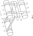
- FIG. 3 is a perspective view of the first winding storage unit 23.
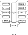
- FIG. 4 is a block diagram illustrating a configuration of the sheet processing apparatus. Note that, in FIG. 1A , the left side represents a front portion of the sheet processing apparatus 1, and the right side represents a rear portion of the sheet processing apparatus 1.
- the sheet processing apparatus 1 illustrated in FIG. 1A is a banknote depositing and dispensing machine that deposits and dispenses banknotes as sheets.
- the sheet processing apparatus 1 comprises a processing unit 10, and a storage box 20 provided below the processing unit 10.
- the processing unit 10 can be drawn forward with respect to the storage box 20.
- the processing unit 10 comprises an upper housing 11.
- an inlet (opening) 121 and an outlet (opening) 131 are provided in a front portion of the upper housing 11, that is, in a front portion of the processing unit 10.
- the inlet 121 is an example of an inlet unit of the present invention.
- the outlet 131 is an example of an outlet unit of the present invention.
- a transport unit 15, a recognition unit 16, the temporary storage unit 17, and a control unit 18 are disposed inside the upper housing 11, that is, inside the processing unit 10, a transport unit 15, a recognition unit 16, the temporary storage unit 17, and a control unit 18 are disposed inside the upper housing 11, that is, inside the processing unit 10, a transport unit 15, a recognition unit 16, the temporary storage unit 17, and a control unit 18 are disposed inside the upper housing 11, that is, inside the processing unit 10, a transport unit 15, a recognition unit 16, the temporary storage unit 17, and a control unit 18 are disposed inside the upper housing 11, that is, inside the processing unit 10, a transport unit 15, a recognition unit 16, the temporary
- a banknote feeding mechanism (not illustrated) that feeds out banknotes one by one to the transport unit 15 in a predetermined cycle is disposed.
- the inlet 121 and the banknote feeding mechanism form a depositing unit 12.
- a stacking mechanism (not illustrated) that piles up banknotes is disposed.
- the outlet 131 and the stacking mechanism form a dispensing unit 13.
- a second dispensing unit 14 having the same configuration as that of the dispensing unit 13 may be provided next to the dispensing unit 13 as needed. Further, the second dispensing unit 14 may have a different configuration from that of the dispensing unit 13.
- a depositing and dispensing unit may be provided by providing an inlet/outlet through which both depositing and dispensing of banknotes are performed, and by disposing a banknote feeding mechanism and a stacking mechanism around the inlet/outlet.
- the inlet/outlet is an example of an inlet and outlet unit of the present invention.
- the transport unit 15 transports banknotes at a predetermined transport speed.
- the transport unit 15 is formed of a belt mechanism or a roller mechanism that transports banknotes.
- the transport unit 15 comprises a loop-shaped transport path 150 that enables banknotes to be transported in one direction and in a direction opposite to the one direction, and a first diversion path 151, a second diversion path 152, a third diversion path 153, a fourth diversion path 154, a fifth diversion path 155, and a sixth diversion path 156 that are diverged from the loop-shaped transport path 150.
- the first diversion path 151 to the fourth diversion path 154 connect the loop-shaped transport path 150 with the depositing unit 12, the dispensing unit 13, the temporary storage unit 17, and a multipurpose storage unit 22 to be described later, respectively.
- the fifth diversion path 155 and the sixth diversion path 156 connect the loop-shaped transport path 150 with the first winding storage units 23 to be described later.
- the recognition unit 16 comprises a sensor such as an image sensor, an optical sensor, and a magnetic sensor, and counts the number of banknotes transported by the transport unit 15 and recognizes the authenticity, denomination, fitness, and the like of a banknote.
- the temporary storage unit 17 temporarily stores banknotes.
- the temporary storage unit 17 takes in and stores banknotes one by one, and feeds out banknotes stored therein one by one.
- the temporary storage unit 17 is formed of a winding storage unit in which a plurality of banknotes is stored in a state of being wound around a rotating body as illustrated in FIG. 2 .
- the temporary storage unit 17 comprises second reels 171Aand 171B, second rollers 172A and 172B, second drum 173, two second tapes 174A, and two second tapes 174B.
- One ends of the two second tapes 174A are apart from each other by a predetermined distance and are connected to the second reel 171A.
- the second reel 171B is disposed such that its axis of rotation is parallel to the axis of rotation of the second reel 171A.
- One ends of the two second tapes 174B are apart from each other by the same distance as that for the second tape 174A and are connected to the second reel 171B.
- the second rollers 172A and 172B are disposed such that their axes of rotation are parallel to each axis of rotation of the second reels 171A and 171B.
- the second rollers 172A and 172B are disposed so as to overlap each of the two second tapes 174A drawn from the second reel 171A and each of the two second tapes 174B drawn from the second reel 171B, and to hold the overlapped tapes therebetween.
- the second drum 173 is disposed such that its axis of rotation is parallel to each axis of rotation of the second reels 171A and 171B and the second rollers 172A and 172B.
- the other ends of the second tapes 174A and 174B are connected to the second drum 173.
- a banknote transported through the third diversion path 153 is inserted between the second tapes 174A drawn from the second reel 171A and the second tapes 174B drawn from the second reel 171B as indicated by an arrow A1.
- the banknote inserted therebetween in this way is wound together with the second tapes 174A and 174B around the second drum 173 by the rotations of the second reels 171A and 171B and the second drum 173. Further, the banknote wound around the second drum 173 is released from the second drum 173 by the rotations of the second reels 171A and 171B and the second drum 173 and is fed out to the third diversion path 153.
- each of the second reels 171A and 172A is divided into two at a predetermined position along the axis of rotation, a half of the second reel 171A and a half of the first second roller 172A move one of the second tapes 174A, and the other half of the second reel 171A and the other half of the second roller 172A move the other one of the second tapes 174A.
- each number of the second tapes 174A and 174B that form the temporary storage unit 17 may be one or may be three or more.
- the second rollers 172A and 172B may be omitted.
- the temporary storage unit 17 may be formed of a stacking storage unit in which a plurality of banknotes is stored in a state of being stacked or may have the same configuration as a configuration of the first winding storage unit 23.
- the configuration of the first winding storage unit 23 will be described later.
- the storage box 20 can be formed of, for example, a safe, and forms a lower housing 21. In a front portion or a rear portion of the lower housing 21, a storage box door (not illustrated) that is lockable is provided. Inside the storage box 20, in order from a front portion thereof, one multipurpose storage unit 22 and eight first winding storage units 23 are disposed.
- the multipurpose storage unit 22 is a stacking storage unit in which a plurality of banknotes is stored in a state of being stacked.
- the multipurpose storage unit 22 is a banknote storage unit usable for various purposes, and is used, for example, for storing overflow banknotes, dispensing reject banknotes, banknotes left behind, counterfeit notes, and suspect notes.
- the overflow banknote refers to a banknote that cannot be stored in a storage unit (the first winding storage unit 23) that is to store the banknote because the storage unit becomes full.
- the dispensing reject banknote refers to, among banknotes fed out from the first winding storage unit 23 when banknote dispensing processing is performed, a banknote that cannot be recognized as normal by the recognition unit 16 due to transport abnormality such as skewing.
- the banknote left behind refers to a banknote that is once dispensed to the dispensing unit 13, but then has not been taken out from the dispensing unit 13 for a predetermined time.
- a stacking table (not illustrated) that ascends and descends in accordance with the amount of banknotes stacked thereon is disposed.
- the multipurpose storage unit 22 is configured to be capable of stacking and storing banknotes transported via the fourth diversion path 154 on the stacking table and feeding out banknotes stacked on the stacking table to the fourth diversion path 154 one by one from above.
- the sixth diversion paths 156 diverged from the fifth diversion path 155 are connected to the eight first winding storage units 23, respectively.
- the eight first winding storage units 23 store, among banknotes sorted based on authenticity, fitness, denomination and the like, banknotes of specific kinds.
- the eight first winding storage units 23 may store banknotes of kinds different from each other. Further, at least two of the first winding storage units 23 may store banknotes of the same kind.
- the first winding storage unit 23 takes in and stores banknotes one by one, and feeds out banknotes stored therein one by one.
- the eight first winding storage units 23 are formed of a common unit, and are set to have the same maximum number of banknotes stored therein.
- the eight first winding storage units 23 are configured such that the maximum number of banknotes stored therein is larger than the maximum number of banknotes stored in the temporary storage unit 17.
- the first winding storage unit 23 comprises a first reel 231, a first drum 232, and two first tapes 233 as illustrated in FIG. 3 .
- One ends of the two first tapes 233 are apart from each other by a predetermined distance and are connected to the first reel 231.
- the first drum 232 is disposed such that its axis of rotation is parallel to the axis of rotation of the first reel 231.
- the other ends of the first tapes 233 are connected to the first drum 232.
- a banknote transported through the sixth diversion path 156 is drawn from the first reel 231 and is inserted between the first tapes 233 before being wound around the first drum 232 and the first tapes 233 each of which is wound around the first drum 232 on an outermost periphery as indicated by arrows A2.
- the banknote inserted therebetween in this way is wound together with the first tapes 233 around the first drum 232 by the rotations of the first reel 231 and the first drum 232.
- the banknote wound around the first drum 232 is released from the first drum 232 by the rotations of the first reel 231 and the first drum 232 and is fed out to the sixth diversion path 156.
- the number of first tapes 233 that form the first winding storage unit 23 may be one or may be three or more. Further, the first winding storage unit 23 may be formed of a stacking storage unit in which a plurality of banknotes is stored in a state of being stacked or may have the same configuration as the configuration of the temporary storage unit 17.
- the control unit 18 comprises at least a central processing unit (CPU) and a memory. As illustrated in FIG. 4 , the depositing unit 12, the dispensing unit 13, the transport unit 15, the temporary storage unit 17, the multipurpose storage unit 22, and the first winding storage unit 23 are connected to the control unit 18 such that signals can be transmitted and received therebetween.
- the depositing unit 12, the dispensing unit 13, the transport unit 15, the temporary storage unit 17, the multipurpose storage unit 22, and the first winding storage unit 23 described above comprise sensors (not illustrated) that detect a banknote during transport.
- each of the first winding storage units 23 is provided with the first sensor 234 and the second sensor 235 that are arranged in a direction in which a banknote is transported as illustrated in FIG. 1B .
- the control unit 18 is capable of recognizing a direction in which a banknote is transported based on a difference between timings of banknote detection by the first sensor 234 and the second sensor 235 that are arranged in the above-described manner. When detection signals of these sensors are inputted, the control unit 18 outputs a control signal based on the detection signals, and controls each unit forming the sheet processing apparatus 1 such that a banknote is transported among the depositing unit 12, the dispensing unit 13, the temporary storage unit 17, the multipurpose storage unit 22, and the first winding storage unit 23 via the transport unit 15. Further, the recognition unit 16, a display 31, an operation unit 32, a communication unit 33, and a memory unit 34 are connected to the control unit 18.
- the display 31 is formed of, for example, a flat panel display, and displays various information.
- the operation unit 32 functions as a human interface portion for an operator of the sheet processing apparatus 1.
- the display 31 and the operation unit 32 may be integrated by configuring such that the display 31 also functions as an operation unit by using a touch screen display.
- the communication unit 33 allows the sheet processing apparatus 1 to transmit and receive signals to and from a higher-ranking terminal (not illustrated) and another apparatus (not illustrated) via a local area network (LAN) or a serial bus, for example.
- LAN local area network
- serial bus for example.
- the memory unit 34 is formed of, for example, a general-purpose storage device such as a hard disk drive and a flash memory.
- the memory unit 34 records, of each number of banknotes stored in the sheet processing apparatus 1 for each denomination and an inventory amount that represents an amount of banknotes stored therein, at least each number of banknotes stored therein for each denomination.
- the memory unit 34 records, of each number of banknotes stored in each storage unit for each denomination and an inventory amount that represents an amount of banknotes stored therein, at least each number of banknotes stored therein for each denomination.
- the memory unit 34 records each inventory amount of the multipurpose storage unit 22 and the first winding storage units 23.
- the memory unit 34 records a serial number list in which serial numbers of banknotes stored in the multipurpose storage unit 22 and the first winding storage units 23 are associated with consecutive numbers corresponding to the number of the banknotes stored therein.
- the serial numbers of the serial number list are arranged in the order in which the banknotes are stored in the multipurpose storage unit 22 and the first winding storage units 23.
- the memory unit 34 records the history of various processing executed by the sheet processing apparatus 1 as a log.
- the depositing processing refers to processing of recognizing a banknote fed out from the depositing unit 12 and storing a banknote recognized as normal (normal banknote) inside the sheet processing apparatus 1.
- An operator places banknotes into the inlet 121, and inputs a command to start depositing processing into the sheet processing apparatus 1 by operating the higher-ranking terminal or the operation unit 32.
- the banknotes in the inlet 121 are fed out one by one by the banknote feeding mechanism of the depositing unit 12, and are then transported to the recognition unit 16 through the transport unit 15.
- the recognition unit 16 recognizes and counts the banknotes.
- the transport unit 15 stores, among the banknotes processed by the recognition unit 16, normal banknotes in the temporary storage unit 17 through the loop-shaped transport path 150 and the third diversion path 153.
- the transport unit 15 transports, among the banknotes processed by the recognition unit 16, reject banknotes, which are not recognized as normal, to the outlet 131 through the loop-shaped transport path 150 and the second diversion path 152.
- the higher-ranking terminal or the display 31 displays a counting result.
- the operator confirms the counting result and then performs a predetermined storage operation on the higher-ranking terminal or the operation unit 32.
- This storage operation causes the temporary storage unit 17 to feed out banknotes stored therein one by one.
- the transport unit 15 stores each of the fed-out banknotes in the first winding storage unit 23 that is predetermined, through the third diversion path 153, the loop-shaped transport path 150, the fifth diversion path 155, and the sixth diversion path 156 based on a recognition result by the recognition unit 16 and a storage allocation set in advance.
- the transport unit 15 dispenses the banknotes stored in the temporary storage unit 17 to the outlet 131.
- the control unit 18 updates the inventory amount, the serial number list and the like that have been recorded in the memory unit 34.
- the dispensing processing refers to processing of dispensing a banknote stored inside the sheet processing apparatus 1.
- An operator inputs a command to start dispensing processing for specifying a denomination of banknotes and a number of the banknotes into the sheet processing apparatus 1 by operating the higher-ranking terminal or the operation unit 32.
- the first winding storage unit 23 that stores banknotes of the specified denomination feeds out the specified number of banknotes stored therein.
- the transport unit 15 then transports the fed-out banknotes to the recognition unit 16 through the sixth diversion path 156, the fifth diversion path 155, and the loop-shaped transport path 150.
- the transport unit 15 dispenses the banknotes recognized by the recognition unit 16 to the outlet 131 through the loop-shaped transport path 150 and the second diversion path 152.
- the control unit 18 updates the inventory amount, the serial number list or the like that have been recorded in the memory unit 34.
- the reconciliation processing refers to processing of performing reconciliation of every banknote stored in at least one of the multipurpose storage unit 22 and the first winding storage units 23.
- the reconciliation processing is performed, for example, when an error occurs at the time of depositing processing or when the storage box door of the storage box 20 is opened or closed.
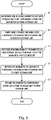
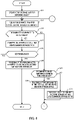
- FIG. 5 illustrates a flowchart for the reconciliation processing.
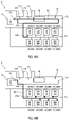
- FIGS. 6A to 6E are diagrams for describing operations of the reconciliation processing. Note that, although recognition of a number of banknotes, a denomination of a banknote, and a serial number of a banknote is exemplified as the contents of the reconciliation, at least a number of banknotes may be detected.
- each number on the lower side of the horizontal line indicates the maximum number of banknotes stored in each unit
- each number on the upper side of the horizontal line indicates the number of banknotes already stored in each unit.
- FIG. 6A indicates that the maximum number of banknotes stored in the temporary storage unit 17 is 300, and each maximum number of banknotes stored in all the first winding storage units 23 is 600. Further, FIG.
- FIG. 6A indicates that the number of banknotes stored in the temporary storage unit 17 is 0, each number of banknotes stored in two of the first winding storage units 23, which are located upward and downward at the left end, is 600, and each number of banknotes stored in the first winding storage units 23 other then the two first winding storage units 23 is 550. That is, FIG. 6A indicates that the number of banknotes that can be stored (hereinafter referred to as "storage available capacity number") in the temporary storage unit 17 is 300, each storage available capacity number in the two first winding storage units 23 located upward and downward at the left end is 0, and each storage available capacity number in the six first winding storage units 23 other then the two first winding storage units 23 is 50, respectively.
- storage available capacity number the number of banknotes that can be stored
- the control unit 18 When reconciliation for the first storage unit 23A is performed, the control unit 18 first controls each unit of the sheet processing apparatus 1 such that one or some banknotes in the first storage unit 23A are recognized by the recognition unit 16 and are temporarily stored in the third storage unit (hereinafter referred to as "temporary storage unit 17" in the description of this reconciliation processing) as illustrated in FIG. 5 (S1). At this time, the control unit 18 recognizes each storage available capacity number in the temporary storage unit 17 and all the second storage units 23B based on information recorded in the memory unit 34.
- the first storage unit 23A feeds out banknotes such that the number of banknotes remaining in the first storage unit 23A becomes equal to or smaller than the total storage available capacity number in all the second storage units 23B.
- the first storage unit 23A feeds out 300 banknotes.
- the transport unit 15 temporarily stores the fed-out banknotes in the temporary storage unit 17 through the sixth diversion path 156, the fifth diversion path 155, the loop-shaped transport path 150, and the third diversion path 153 as indicated by an arrow B1 in FIG. 6A .
- the control unit 18 updates the serial number list or the like in the memory unit 34.
- the numbers of banknotes stored in the temporary storage unit 17, the first storage unit 23A, and the second storage units 23B are as illustrated in FIG. 6B .
- the transport unit 15 temporarily stores the banknotes temporarily stored in the temporary storage unit 17 in the second storage units 23B as illustrated in FIG. 5 (S2). At this time, the transport unit 15 may preferentially store the banknotes fed out from the temporary storage unit 17 in the second storage unit(s) 23B located on an upstream side of the banknote transport at the time of storage (the left side in FIG. 6B ).
- the transport unit 15 may not disperse the banknotes in the six second storage units 23B, but may store the banknotes only in the one or two second storage units 23B.
- the second storage unit(s) 23B located on the upstream side of the banknote transport mean the second storage unit(s) 23B for which the banknote transport path from the temporary storage unit 17 is shorter.
- the transport unit 15 may preferentially store the banknotes fed out from the temporary storage unit 17 in the second storage unit(s) 23B with a large storage available capacity number.
- the transport unit 15 may not disperse the banknotes in the six second storage units 23B, but may store the banknotes only in the one or two second storage units 23B.
- Such a configuration makes it possible to reduce the number of second storage units 23B used in banknote storage. Accordingly, it is possible to reduce the number of switching from the fifth diversion path 155 to the sixth diversion path 156 at the time of banknote storage, and it is possible to reduce the risk of occurrence of jams or the like at the time of the switching.
- the transport unit 15 may store the banknotes fed out from the temporary storage unit 17 in every second storage unit 23B capable of storing the banknotes. At this time, the transport unit 15 may store the banknotes such that the numbers of banknotes temporarily stored in each of the second storage units 23B become the same, or may store the banknotes such that the numbers of banknotes stored in each of the second storage units 23B after temporary storage become the same.
- the transport unit 15 temporarily stores 300 banknotes in the temporary storage unit 17 in six of the second storage units 23B, with 50 banknotes for each second storage unit 23B, through the third diversion path 153, the loop-shaped transport path 150, the fifth diversion path 155, and each of the sixth diversion paths 156 as indicated by an arrow B2 in FIG. 6B .
- the control unit 18 updates the serial number list or the like in the memory unit 34.
- the numbers of banknotes stored in the temporary storage unit 17, the first storage unit 23A, and the second storage units 23B are as illustrated in FIG. 6C .
- the banknotes when the banknotes are temporarily stored in the second storage units 23B, it may be configured as below in order to facilitate a distinction between temporarily stored banknotes and banknotes stored in the second storage units 23B before the temporary storage. That is, the gap between a banknote, which has been stored first among temporarily stored banknotes, and a banknote, which has been stored last among banknotes stored in the second storage units 23B before the temporary storage, may be configured to be larger than the gap between the temporarily stored banknotes and the gap between the banknotes stored in the second storage units 23B before the temporary storage. Further, when the banknotes are temporarily stored in the second storage units 23B, recognition processing by the recognition unit 16 may be performed.
- the control unit 18 controls each unit of the sheet processing apparatus 1 such that remaining banknote or banknotes in the first storage unit 23A are recognized by the recognition unit 16 and are temporarily stored in the temporary storage unit 17 as illustrated in FIG. 5 (S3).
- the transport unit 15 stores 300 banknotes fed out from the first storage unit 23A in the temporary storage unit 17 through the sixth diversion path 156, the fifth diversion path 155, the loop-shaped transport path 150, and the third diversion path 153 as indicated by an arrow B3 in FIG. 6C , for example.
- the control unit 18 updates the serial number list or the like in the memory unit 34.
- the numbers of banknotes stored in the temporary storage unit 17, the first storage unit 23A, and the second storage units 23B are as illustrated in FIG. 6D .
- the transport unit 15 returns the banknote or banknotes temporarily stored in the temporary storage unit 17 to the first storage unit 23A as illustrated in FIG. 5 (S4).
- the transport unit 15 returns the banknote or banknotes in the temporary storage unit 17 to the first storage unit 23A through the third diversion path 153, the loop-shaped transport path 150, the fifth diversion path 155, and the sixth diversion path 156 as indicated by an arrow B4 in FIG. 6D , for example.
- the control unit 18 updates the serial number list or the like in the memory unit 34.
- the numbers of banknotes stored in the temporary storage unit 17, the first storage unit 23A, and the second storage units 23B are as illustrated in FIG. 6E . Note that, when the banknote or banknotes are returned to the first storage unit 23A, recognition processing by the recognition unit 16 may be performed.
- the transport unit 15 returns the banknotes temporarily stored in the second storage units 23B to the first storage unit 23A as illustrated in FIG. 5 (S5). At this time, the transport unit 15 returns the banknotes in the second storage units 23B to the first storage unit 23A through each of the sixth diversion paths 156 and the fifth diversion path 155 as indicated by an arrow B5 in FIG. 6E , for example. While or after the banknotes are returned to the first storage unit 23A, the control unit 18 updates the serial number list or the like in the memory unit 34. As a result of the processing described above, the numbers of banknotes stored in the temporary storage unit 17, the first storage unit 23A, and the second storage units 23B are as illustrated in FIG. 6A , and the reconciliation processing ends.
- Embodiment 1 even when the temporary storage unit 17 in which the maximum number of banknotes stored therein is smaller than the maximum number of banknotes stored in the first storage unit 23A is used, it is possible to perform reconciliation processing of every banknote in the first storage unit 23A by temporarily storing the banknotes in the first storage unit 23A in the second storage units 23B and the temporary storage unit 17, respectively. Accordingly, it is possible to reduce the placement space for the temporary storage unit 17 and to miniaturize the sheet processing apparatus 1.
- banknotes having different sizes can be stored in the one first storage unit 23A, the second storage units 23B or the temporary storage unit 17 as needed.
- a banknote can be transported while being held between the second tapes 174A and 174B located on both sides of the banknote, respectively, between the second rollers 172A and 172B and the second drum 173. Accordingly, it is possible to ensure that a banknote is wound around the second drum 173. Further, in the first storage unit 23A and the second storage units 23B, a banknote and the first tapes located on one side of the banknote are wound around the first drum 232 while the banknote overlaps the first tapes so that it is possible to reduce the thickness of a wound product in comparison with a configuration as in the temporary storage unit 17 in which a banknote is wound together with tapes located on both sides of the banknote, respectively. Accordingly, it is possible to increase the maximum numbers of banknotes stored in the first storage unit 23A and the second storage units 23B without increasing the placement spaces for the first storage unit 23A and the second storage units 23B.
- the maximum number of banknotes stored in the first storage unit 23A and the maximum numbers of banknotes stored in the second storage units 23B are configured to be equal to each other, it is possible to use a common unit.
- the first storage unit 23A and the second storage units 23B are housed in the storage box 20 formed of the safe, and the recognition unit 16 and the temporary storage unit 17 are disposed outside the storage box 20, it is possible to miniaturize the sheet processing apparatus 1 having the general structure as such.
- Embodiment 2 of the present invention a sheet processing apparatus according to Embodiment 2 of the present invention will be described. Note that, a description will be given by denoting the same configurations as those in the sheet processing apparatus 1 of Embodiment 1 with the same names and the same reference signs.
- a sheet processing apparatus 1A of Embodiment 2 differs from the sheet processing apparatus 1 of Embodiment 1 in the configurations of the depositing unit 12 and the dispensing unit 13.
- the depositing unit 12 comprises, in addition to the configurations in Embodiment 1, a depositing shutter 122 indicated by a two-dot chain line.
- the depositing shutter 122 opens and closes the inlet 121 by sliding near the opening of the inlet 121.
- the dispensing unit 13 comprises, in addition to the configurations in Embodiment 1, a dispensing shutter 132 indicated by a two-dot chain line, and a retract mechanism (not illustrated).
- the dispensing shutter 132 opens and closes the outlet 131 by sliding near the opening of the outlet 131.
- the retract mechanism takes in a banknote in the outlet 131 into the second diversion path 152.
- the reconciliation processing of Embodiment 2 is performed based on the flow chart of FIG. 5 in Embodiment 1. Specifically, when reconciliation for the first storage unit (hereinafter referred to as “first winding storage unit 23 on the upper-left side” in the description of this reconciliation processing) is performed, the depositing shutter 122 and dispensing shutter 132 close the inlet 121 and the outlet 131. Next, the control unit 18 controls each unit of the sheet processing apparatus 1A such that one or some banknotes in the first winding storage unit 23 on the upper-left side are recognized by the recognition unit 16 and are temporarily stored in the third storage unit (hereinafter referred to as "temporary storage unit 17" in the description of this reconciliation processing) (S1).
- the transport unit 15 temporarily stores the banknotes temporarily stored in the temporary storage unit 17 in the second storage unit (hereinafter referred to as "at least one of the inlet 121 and the outlet 131" in the description of this reconciliation processing) (S2).
- the control unit 18 controls each unit of the sheet processing apparatus 1A such that remaining banknote or banknotes in the first winding storage unit 23 on the upper left side are recognized by the recognition unit 16 and are temporarily stored in the temporary storage unit 17 (S3).
- the transport unit 15 returns the banknote or banknotes temporarily stored in the temporary storage unit 17 to the first winding storage unit 23 on the upper-left side (S4).
- the transport unit 15 returns the banknotes temporarily stored in at least one of the inlet 121 and the outlet 131 to the first winding storage unit 23 on the upper-left side (S5).
- the reconciliation processing ends with the above-described processing.
- Embodiment 2 achieves the following working effect in addition to the same working effects as those of Embodiment 1.
- the inlet 121 and the outlet 131 generally comprised by the sheet processing apparatus 1A can be effectively utilized as the second storage unit that temporarily stores banknotes at the time of reconciliation processing.
- FIG. 7 is a schematic view illustrating an internal structure of a sheet processing apparatus 1B. Note that, a description will be given by denoting the same configurations as those in the sheet processing apparatus 1 of Embodiment 1 with the same names and the same reference signs.
- the sheet processing apparatus 1B illustrated in FIG. 7 differs from the sheet processing apparatus 1 according to Embodiment 1 in the configuration of the transport unit 15 and the configuration inside the storage box 20.
- the transport unit 15 comprises the first diversion path 151 to the third diversion path 153, the fifth diversion path 155, the sixth diversion path 156, a seventh diversion path 157, an eighth diversion path 158, a ninth diversion path 159, and a tenth diversion path 160.
- first stacking storage units 24, one second winding storage unit 25, six first winding storage units 23, and one second stacking storage unit 26 are disposed inside the storage box 20, in order from the front portion thereof.
- the first stacking storage unit 24 on the upper side is connected to the loop-shaped transport path 150 via the seventh diversion path 157.
- the first stacking storage unit 24 on the lower side is connected to the loop-shaped transport path 150 via the eighth diversion path 158 diverged from the fifth diversion path 155 and via the ninth diversion path 159 diverged from the eighth diversion path 158.
- the first stacking storage unit 24 is configured in the same manner as the multipurpose storage unit 22 of Embodiment 1, and is configured to be capable of stacking and storing banknotes on a stacking table and feeding out banknotes stacked on the stacking table to the seventh diversion path 157 or the ninth diversion path 159 one by one from above.
- the first stacking storage unit 24 comprising two storage compartments along the vertical direction may also be provided.
- the seventh diversion path 157 is connected to the storage compartment in an upper portion of the first stacking storage unit 24, and the ninth diversion path 159 is connected to the storage compartment in a lower portion of the first stacking storage unit 24.
- the second winding storage unit 25 is connected to the loop-shaped transport path 150 via the eighth diversion path 158 and the fifth diversion path 155.
- the second winding storage unit 25 is configured to wind and store banknotes.
- the second winding storage unit 25 is configured such that the maximum number of banknotes stored therein is smaller than the maximum number of banknotes stored in the first winding storage unit 23.
- the second winding storage unit 25 may also be configured such that two tapes and a banknote held between the tapes are wound while the tapes and the banknote overlap each other as in the temporary storage unit 17 or may be configured such that a banknote and tapes located on one side of the banknote are wound while the banknote overlaps the tapes as in the first winding storage unit 23.
- the second stacking storage unit 26 is connected to the tenth diversion path 160 diverged from the loop-shaped transport path 150.
- the second stacking storage unit 26 is configured such that the maximum number of banknotes stored therein is larger than the maximum number of banknotes stored in the first stacking storage unit 24.
- the second stacking storage unit 26 is configured in the same manner as the first stacking storage unit 24, and is configured to be capable of stacking and storing banknotes on a stacking table and feeding out banknotes stacked on the stacking table to the tenth diversion path 160 one by one from above.
- Each of the first stacking storage unit 24, the second winding storage unit 25, and the second stacking storage unit 26 comprises sensors (not illustrated) that detect a banknote during transport.
- the control unit 18 outputs a control signal based on the detection signals, and controls each unit forming the sheet processing apparatus 1B such that the banknote is transported among the depositing unit 12, the dispensing unit 13, the temporary storage unit 17, the first winding storage unit 23, the first stacking storage unit 24, the second winding storage unit 25, and the second stacking storage unit 26 via the transport unit 15.
- Table 3 indicates configurations corresponding to the first storage unit, the second storage unit and the third storage unit of the present invention in Embodiment 3, respectively.
- First storage unit Second stacking storage unit 26 Second storage unit All first winding storage units 23, all first stacking storage units 24, second winding storage unit 25
- the control unit 18 controls each unit of the sheet processing apparatus 1B such that one or some banknotes in the second stacking storage unit 26 are recognized by the recognition unit 16 and are temporarily stored in the third storage unit (hereinafter referred to as “temporary storage unit 17" in the description of this reconciliation processing) as illustrated in FIG. 5 (S1).
- the transport unit 15 temporarily stores the banknotes temporarily stored in the temporary storage unit 17 in the second storage unit (hereinafter referred to as "at least one of all the first winding storage units 23, all the first stacking storage units 24, and the second winding storage unit 25" in the description of this reconciliation processing) (S2).
- control unit 18 controls each unit of the sheet processing apparatus 1B such that remaining banknote or banknotes in the second stacking storage unit 26 are recognized by the recognition unit 16 and are temporarily stored in the temporary storage unit 17 (S3). Thereafter, the transport unit 15 returns the banknote or banknotes temporarily stored in the temporary storage unit 17 to the second stacking storage unit 26 (S4). Then the transport unit 15 returns the banknotes temporarily stored in at least one of all the first winding storage units 23, all the first stacking storage units 24, and the second winding storage unit 25 to the second stacking storage unit 26 (S5).
- the reconciliation processing ends with the above-described processing.
- Embodiment 3 even when the temporary storage unit 17 in which the maximum number of banknotes stored therein is smaller than the maximum number of banknotes stored in the second stacking storage unit 26 is used, it is possible to perform reconciliation processing of every banknote in the second stacking storage unit 26 by temporarily storing the banknotes in the second stacking storage unit 26 in the first winding storage units 23, the first stacking storage units 24, the second winding storage unit 25, and the temporary storage unit 17, respectively. Accordingly, it is possible to reduce the placement space for the temporary storage unit 17 and to miniaturize the sheet processing apparatus 1B.
- Embodiment 4 of the present invention is the same as Embodiment 3 in terms of using the sheet processing apparatus 1B, but places where banknotes are temporarily stored differ between Embodiments 3 and 4.
- Table 4 indicates configurations corresponding to the first storage unit, the second storage unit and the third storage unit of the present invention in Embodiment 4, respectively. Note that, although a case where the first stacking storage unit 24 on the upper side is applied as the third storage unit of the present invention is exemplified in Embodiment 4, the first stacking storage unit 24 on the lower side may be applied.
- First storage unit Second stacking storage unit 26 Second storage unit Temporary storage unit 17, all first winding storage units 23, second winding storage unit 25 Third storage unit First stacking storage unit 24 on the upper side
- the control unit 18 controls each unit of the sheet processing apparatus 1B such that one or some banknotes in the second stacking storage unit 26 are recognized by the recognition unit 16 and are temporarily stored in the third storage unit (hereinafter referred to as “first stacking storage unit 24 on the upper side” in the description of this reconciliation processing) as illustrated in FIG. 5 (S1).
- the transport unit 15 temporarily stores the banknotes temporarily stored in the first stacking storage unit 24 on the upper side in the second storage unit (hereinafter referred to as "at least one of the temporary storage unit 17, all the first winding storage units 23, and the second winding storage unit 25" in the description of this reconciliation processing) (S2).
- the control unit 18 controls each unit of the sheet processing apparatus 1B such that remaining banknote or banknotes in the second stacking storage unit 26 are recognized by the recognition unit 16 and are temporarily stored in the first stacking storage unit 24 on the upper side (S3).
- the transport unit 15 returns the banknote or banknotes temporarily stored in the first stacking storage unit 24 on the upper side to the second stacking storage unit 26 (S4).
- the transport unit 15 returns the banknotes temporarily stored in at least one of the temporary storage unit 17, all the first winding storage units 23, and the second winding storage unit 25 to the second stacking storage unit 26 (S5).
- the reconciliation processing ends with the above-described processing.
- Embodiment 4 even when one first stacking storage unit 24 in which the maximum number of banknotes stored therein is smaller than the maximum number of banknotes stored in the second stacking storage unit 26 is used, it is possible to perform reconciliation processing of every banknote in the second stacking storage unit 26 by temporarily storing the banknotes in the second stacking storage unit 26 in the temporary storage unit 17, the first winding storage units 23, the one first stacking storage unit 24, and the second winding storage unit 25, respectively. Accordingly, it is possible to reduce the placement spaces for the first stacking storage units 24 and to miniaturize the sheet processing apparatus 1B.
- Embodiment 5 of the present invention is the same as Embodiment 3 in terms of using the sheet processing apparatus 1B, but places where banknotes are temporarily stored differ between Embodiments 3 and 5.
- Table 5 indicates configurations corresponding to the first storage unit, the second storage unit and the third storage unit of the present invention in Embodiment 5, respectively.
- [Table 5] First storage unit First winding storage unit 23 on the upper-left side Second storage unit All first stacking storage units 24, second winding storage unit 25, second stacking storage unit 26 Third storage unit Temporary storage unit 17
- the control unit 18 controls each unit of the sheet processing apparatus 1B such that one or some banknotes in the first winding storage unit 23 on the upper-left side are recognized by the recognition unit 16 and are temporarily stored in the third storage unit (hereinafter referred to as “temporary storage unit 17" in the description of this reconciliation processing) as illustrated in FIG. 5 (S1).
- the transport unit 15 temporarily stores the banknotes temporarily stored in the temporary storage unit 17 in the second storage unit (hereinafter referred to as "at least one of all the first stacking storage units 24, the second winding storage unit 25, and the second stacking storage unit 26" in the description of this reconciliation processing) (S2).
- the control unit 18 controls each unit of the sheet processing apparatus 1B such that remaining banknote or banknotes in the first winding storage unit 23 on the upper-left side are recognized by the recognition unit 16 and are temporarily stored in the temporary storage unit 17 (S3).
- the transport unit 15 returns the banknote or banknotes temporarily stored in the temporary storage unit 17 to the first winding storage unit 23 on the upper-left side (S4).
- the transport unit 15 returns the banknotes temporarily stored in at least one of all the first stacking storage units 24, the second winding storage unit 25, and the second stacking storage unit 26 to the first winding storage unit 23 on the upper-left side (S5).
- the reconciliation processing ends with the above-described processing.
- Embodiment 5 even when the temporary storage unit 17 in which the maximum number of banknotes stored therein is smaller than the maximum number of banknotes stored in one of the first winding storage units 23 is used, it is possible to perform reconciliation processing of every banknote in one first winding storage unit 23 by temporarily storing the banknotes in the one first winding storage unit 23 in the temporary storage unit 17, the first stacking storage units 24, the second winding storage unit 25, and the second stacking storage unit 26, respectively. Accordingly, it is possible to reduce the placement space for the temporary storage unit 17 and to miniaturize the sheet processing apparatus 1B.
- Embodiment 6 of the present invention is the same as Embodiment 3 in terms of using the sheet processing apparatus 1B, but places where banknotes are temporarily stored differ between Embodiments 3 and 6. Further, as reconciliation processing, denomination recognition using the recognition unit 16 is not performed and only the number of banknotes is detected using the sensors of the second winding storage unit 25 in Embodiment 6.
- the sensors of the second winding storage unit 25 the same configurations as the first sensor 234 and the second sensor 235 illustrated in FIG. 1B may be applied, for example.
- Table 6 indicates configurations corresponding to the first storage unit, the second storage unit and the third storage unit of the present invention in Embodiment 6, respectively. [Table 6 First storage unit First winding storage unit 23 on the upper-left side Second storage unit First winding storage units 23 other than first winding storage unit 23 on the upper-left side, all first stacking storage units 24 Third storage unit Second winding storage unit 25
- the control unit 18 controls each unit of the sheet processing apparatus 1B such that one or some banknotes in the first winding storage unit 23 on the upper-left side are not taken out from the storage box 20, but are temporarily stored in the third storage unit (hereinafter referred to as “second winding storage unit 25" in the description of this reconciliation processing).
- the sensors of the second winding storage unit 25, which are an example of the detection unit of the present invention, detect the number of the stored banknotes, and output detection signals to the control unit 18.
- the control unit 18 updates the number of banknotes stored in the second winding storage unit 25, where the number of banknotes has been recorded in the memory unit 34, based on the detection signals from the second winding storage unit 25.
- the transport unit 15 does not take out the banknotes temporarily stored in the second winding storage unit 25 from the storage box 20, but temporarily stores the banknotes in the second storage unit (hereinafter referred to as "at least one of the first winding storage units 23 other than the first winding storage unit 23 on the upper-left side and all the first stacking storage units 24" in the description of this reconciliation processing).
- the transport unit 15 does not take out remaining banknote or banknotes in the first winding storage unit 23 on the upper-left side from the storage box 20, but temporarily stores the banknote or banknotes in the second winding storage unit 25.
- the control unit 18 also updates the number of banknotes stored in the second winding storage unit 25 based on the detection signals from the second winding storage unit 25.
- the transport unit 15 does not take out the banknote or banknotes temporarily stored in the second winding storage unit 25 from the storage box 20, but returns the banknote or banknotes to the first winding storage unit 23 on the upper-left side.
- the transport unit 15 does not take out the banknotes temporarily stored in at least one of the first winding storage units 23 other than the first winding storage unit 23 on the upper-left side and all the first stacking storage units 24 from the storage box 20, but returns the banknotes to the first winding storage unit 23 on the upper-left side.
- the reconciliation processing ends with the above-described processing.
- Embodiment 6 even when the second winding storage unit 25 in which the maximum number of banknotes stored therein is smaller than the maximum number of banknotes stored in one of the first winding storage units 23 is used, it is possible to perform detection processing of the number of every banknote in one first winding storage unit 23 by temporarily storing the banknotes in the one first winding storage unit 23 in the first winding storage units 23 other than the one first winding storage unit 23, the first stacking storage units 24, and the second winding storage unit 25, respectively. Accordingly, it is possible to reduce the placement space for the second winding storage unit 25 and to miniaturize the sheet processing apparatus 1B. Further, it is possible to perform detection processing of the number of banknotes without taking out the banknotes from the storage box 20. Further, since the movement distance of banknotes can be shortened in comparison with a case where banknotes are taken out from the storage box 20 and detection processing of the number of the banknotes is performed, it is possible to reduce the risk of jams of banknotes.
- the mixed dispensing processing refers to processing of dispensing a banknote of a predetermined denomination from one first winding storage unit 23 in which banknotes of a plurality of denominations are stored.
- FIG. 8 illustrates a flowchart for the mixed dispensing processing. Note that, configurations corresponding to the first storage unit, the second storage unit, and the third storage unit of the present invention in Embodiment 7, respectively, are as illustrated in Table 1.
- the control unit 18 specifies, as the first storage unit, one first winding storage unit 23 capable of dispensing the number of banknotes of the denomination to be dispensed (hereinafter referred to as "first winding storage unit 23 for the dispensing object" in the description of this mixed dispensing processing) based on the serial number list and denomination of each of the first winding storage units 23, which have been recorded in the memory unit 34 (S11).
- control unit 18 controls each unit of the sheet processing apparatus 1 such that one banknote is fed out from the first winding storage unit 23 for the dispensing object, is transported to the recognition unit 16 via the sixth diversion path 156, the fifth diversion path 155, and the loop-shaped transport path 150, and is recognized by the recognition unit 16 (S12). The control unit 18 then determines whether the recognized banknote is a banknote to be dispensed (S13).
- control unit 18 determines whether the banknote can be temporarily stored in the third storage unit (hereinafter referred to as "temporary storage unit 17" in the description of this mixed dispensing processing) (S14). In a case where the control unit 18 determines that the banknote can be temporarily stored in the temporary storage unit 17 (S14: YES), the control unit 18 causes the transport unit 15 to temporarily store the banknote in the temporary storage unit 17, and updates the banknote storage status of the first winding storage unit 23 for the dispensing object and the temporary storage unit 17, where the banknote storage status has been recorded in the memory unit 34 (S15).
- the control unit 18 determines that the banknote cannot be temporarily stored in the temporary storage unit 17 (S14: NO)
- the control unit 18 causes the transport unit 15 to temporarily store the banknote in the second storage unit (hereinafter referred to as "first winding storage units 23 not for the dispensing object" in the description of this mixed dispensing processing), and updates the banknote storage status of the first winding storage unit 23 for the dispensing object and the first winding storage units 23 not for the dispensing object (S16).
- the control unit 18 causes the processing in S12 to be performed.
- control unit 18 determines that the banknote recognized by the recognition unit 16 is a banknote to be dispensed (S13: YES)
- the control unit 18 causes the transport unit 15 to transport the banknote to the outlet 131, and updates the banknote storage status of the first winding storage unit 23 for the dispensing object (S17). Thereafter, the control unit 18 determines whether to end the dispensing (S18). In a case where the control unit 18 determines that transport of every banknote to be dispensed to the outlet 131 is not completed and the dispensing is not ended (SI8: NO), the control unit 18 causes the processing in S12 to be performed.
- control unit 18 determines that the transport of every banknote to be dispensed to the outlet 131 is completed and the dispensing is ended (SI8: YES), on the other hand, the control unit 18 controls the transport unit 15 such that banknotes temporarily stored in the first winding storage units 23 not for the dispensing object and the temporary storage unit 17 are returned to the first winding storage unit 23 for the dispensing object (S19).
- the mixed dispensing processing ends with the above-described processing.
- the control unit 18 may recognize a denomination whose banknotes are frequently dispensed, based on banknote storage status recorded in the memory unit 34, and the transport unit 15 may return the temporarily stored banknotes to the first winding storage unit 23 for the dispensing object such that banknotes of the denomination recognized by the control unit 18 can be preferentially dispensed at the time of the next mixed dispensing.
- banknotes of a denomination which are not frequently dispensed may be first returned to the first winding storage unit 23 for the dispensing object and then banknotes of a denomination which are frequently dispensed may be returned to the first winding storage unit 23 for the dispensing object.
- the concept of preferentially dispensing banknotes of a denomination which are frequently dispensed also comprises, in addition to the concept of first dispensing banknotes of a denomination which are frequently dispensed, the concept of first dispensing several banknotes of a denomination which are not frequently dispensed and then dispensing banknotes of denomination which are frequently dispensed. Such a configuration makes it possible to end the mixed dispensing quickly.
- the transport unit 15 may return every banknote temporarily stored in the temporary storage unit 17 to the first winding storage unit 23 for the dispensing object and then return every banknote temporarily stored in the first winding storage units 23 not for the dispensing object to the first winding storage unit 23 for the dispensing object.
- Embodiment 7 even when the temporary storage unit 17 in which the maximum number of banknotes stored therein is smaller than one of the first winding storage units 23 is used, it is possible to perform mixed dispensing processing of banknotes in the one first winding storage unit 23 by temporarily storing the banknotes in the one first winding storage unit 23 in the first winding storage units 23 other than the one first winding storage unit 23 and the temporary storage unit 17. Accordingly, it is possible to reduce the placement space for the temporary storage unit 17 and to miniaturize the sheet processing apparatus 1.
- the transport unit 15 When reconciliation for the first winding storage unit 23 on the upper-left side (the first storage unit) is performed, the transport unit 15 does not take out every banknote in the first storage unit from the storage box 20, but temporarily stores the banknotes in the first winding storage units 23 (the second storage unit) other than the first storage unit.
- the control unit 18 updates, based on detection signals from the first sensor 234 and the second sensor 235 of the second storage unit, the number of banknotes stored in the second storage unit, where the number of banknotes has been recorded in the memory unit 34.
- the transport unit 15 does not take out the banknotes temporarily stored in the second storage unit from the storage box 20, but returns the banknotes to the first storage unit, and the control unit 18 updates the number of banknotes stored in the second storage unit.
- the reconciliation processing ends with the above-described processing.
- the processing in S4 and the processing in S5 may be interchanged.
- the banknotes temporarily stored in at least one of the first winding storage units 23 other than the first winding storage unit 23 on the upper-left side and all the first stacking storage units 24 (the second storage unit) may be returned to the first winding storage unit 23 on the upper-left side (the first storage unit) and then the banknotes temporarily stored in the second winding storage unit 25 (the third storage unit) may be returned to the first winding storage unit 23 on the upper-left side.
- the order in which banknotes are stored in the first storage unit after reconciliation processing differs from the order in which banknotes are stored in the first storage unit before the reconciliation processing so that the serial number list is preferably updated in accordance with the order in which banknotes are stored in the first storage unit after the reconciliation processing.
- the destinations in which banknotes are temporarily stored in the reconciliation processing in S1 to S5 of FIG. 5 may be configured as follows. First, the control unit 18 causes one or some banknotes in the first storage unit to be recognized by the recognition unit 16 and to be temporarily stored in the second storage unit. Next, the control unit 18 causes the banknotes temporarily stored in the second storage unit to be temporarily stored in the third storage unit. Thereafter, the control unit 18 causes remaining banknote or banknotes in the first storage unit to be recognized by the recognition unit 16 and to be temporarily stored in the second storage unit. Thereafter, the control unit 18 causes the banknote or banknotes temporarily stored in one of the second storage unit and the third storage unit to be returned to the first storage unit. Then, the control unit 18 causes the banknote or banknotes temporarily stored in the other one of the second storage unit and the third storage unit to be returned to the first storage unit.
- the destinations in which banknotes are temporarily stored in the reconciliation processing may be configured as follows. First, the control unit 18 causes one or some banknotes in the first storage unit not to be taken out from the storage box 20, but to be temporarily stored in the second storage unit. Next, the control unit 18 causes the banknotes temporarily stored in the second storage unit not to be taken out from the storage box 20, but to be temporarily stored in the third storage unit. Thereafter, the control unit 18 causes remaining banknote or banknotes in the first storage unit not to taken out from the storage box 20, but to be temporarily stored in the second storage unit.
- control unit 18 causes the banknote or banknotes temporarily stored in one of the second storage unit and the third storage unit not to be taken out from the storage box 20, but to be returned to the first storage unit. Then, the control unit 18 causes the banknote or banknotes temporarily stored in the other one of the second storage unit and the third storage unit not to be taken out from the storage box 20, but to be returned to the first storage unit.
- the mixed dispensing processing in Embodiment 7 may be performed using the sheet processing apparatus 1B illustrated in FIG. 7
- the configurations illustrated in Tables 3 to 6 may be applied as configurations corresponding to the "first storage unit", "second storage unit”, and "third storage unit” illustrated in the flowchart of FIG. 8 .
- the present invention is useful for a sheet processing apparatus that processes a sheet.
Abstract
Description
- The present invention relates to a sheet processing apparatus.
- In the related art, there is known a sheet processing apparatus that deposits and dispenses banknotes (for example, see Patent Literature (hereinafter referred to as "PTL") 1).
PTL 1 discloses reconciliation processing of feeding out every banknote stored in a storage module once, recognizing and counting the banknotes by a recognition unit, and returning the banknotes to the storage module again.PTL 1 discloses that in the reconciliation processing, another storage module or a temporary storage unit is used as a storage destination of banknotes fed out from the storage module. -
PTL 1
Japanese Patent Application Laid-Open No. 2012-198764 - The configuration as in
PTL 1, however, requires configuring such that the maximum number of banknotes stored in the storage module or the temporary storage unit as the storage destination is larger than the maximum number of banknotes stored in the storage module as the feeding source, and is therefore incapable of easily miniaturizing the apparatus. - An object of the present invention is to provide a sheet processing apparatus which can be easily miniaturized.
- A sheet processing apparatus of the present invention comprises: a transport unit configured to transport a sheet; a detection unit configured to detect a number of the sheets transported by the transport unit; a first storage unit, a second storage unit, and a third storage unit each of which is configured to store the sheet transported by the transport unit; and a control unit. A maximum number of the sheets stored in the third storage unit is smaller than a maximum number of the sheets stored in the first storage unit. The control unit controls the transport unit such that the sheets stored in the first storage unit are temporarily stored in each of the second storage unit and the third storage unit, and the control unit controls the detection unit such that the number of the sheets is detected while the sheets are transported.
- According to the present invention, it is possible to provide a sheet processing apparatus which can be easily miniaturized.
-
-
FIG. 1A is a schematic view illustrating internal structures of sheet processing apparatuses according toEmbodiments -
FIG. 1B is a schematic view of a first sensor and a second sensor of a first winding storage unit of the sheet processing apparatuses; -
FIG. 2 is a perspective view of a temporary storage unit of the sheet processing apparatuses; -
FIG. 3 is a perspective view of the first winding storage unit of the sheet processing apparatuses; -
FIG. 4 is a block diagram illustrating a configuration of the sheet processing apparatuses; -
FIG. 5 illustrates a flowchart for reconciliation processing according toEmbodiments 1 to 5; -
FIG. 6A is a diagram for describing an operation of reconciliation processing according toEmbodiment 1; -
FIG. 6B is a diagram for describing an operation of the reconciliation processing according toEmbodiment 1; -
FIG. 6C is a diagram for describing an operation of the reconciliation processing according toEmbodiment 1; -
FIG. 6D is a diagram for describing an operation of the reconciliation processing according toEmbodiment 1; -
FIG. 6E is a diagram for describing an operation of the reconciliation processing according toEmbodiment 1; -
FIG. 7 is a schematic view illustrating an internal structure of sheet processing apparatuses according toEmbodiments 3 to 6 of the present invention; and -
FIG. 8 illustrates a flowchart for mixed dispensing processing according to Embodiment 7. - Hereinafter, embodiments of the present invention will be described with reference to the accompanying drawings. In the present embodiment, a sheet processing apparatus that deposits and dispenses banknotes that are an example of sheets will be exemplified. The sheets are not limited to banknotes, but may be vouchers, securities, ballots, and the like. Note that, in the following description, the "front" of the sheet processing apparatus means a side of an operator who performs at least one operation of sheet placement operation and sheet discharge operation through an opening provided in a processing unit, and the "rear" of the sheet processing apparatus means the opposite side thereto. In other words, the "front" of the sheet processing apparatus means a side provided with an opening for performing at least one operation of sheet placement operation and sheet discharge operation. Further, the "left" of the sheet processing apparatus means the left side when viewed from the operator facing the opening, and the "right" of the sheet processing apparatus means the right side when viewed from the operator facing the opening.
- First, a sheet processing apparatus according to
Embodiment 1 of the present invention will be described.FIG. 1A is a schematic view illustrating an internal structure of asheet processing apparatus 1.FIG. 1B is a schematic view of afirst sensor 234 and asecond sensor 235 of a firstwinding storage unit 23.FIG. 2 is a perspective view of atemporary storage unit 17.FIG. 3 is a perspective view of the firstwinding storage unit 23.FIG. 4 is a block diagram illustrating a configuration of the sheet processing apparatus. Note that, inFIG. 1A , the left side represents a front portion of thesheet processing apparatus 1, and the right side represents a rear portion of thesheet processing apparatus 1. - The
sheet processing apparatus 1 illustrated inFIG. 1A is a banknote depositing and dispensing machine that deposits and dispenses banknotes as sheets. Thesheet processing apparatus 1 comprises aprocessing unit 10, and astorage box 20 provided below theprocessing unit 10. Theprocessing unit 10 can be drawn forward with respect to thestorage box 20. - The
processing unit 10 comprises anupper housing 11. In a front portion of theupper housing 11, that is, in a front portion of theprocessing unit 10, an inlet (opening) 121 and an outlet (opening) 131 are provided. Theinlet 121 is an example of an inlet unit of the present invention. Theoutlet 131 is an example of an outlet unit of the present invention. Inside theupper housing 11, that is, inside theprocessing unit 10, atransport unit 15, arecognition unit 16, thetemporary storage unit 17, and acontrol unit 18 are disposed. Therecognition unit 16 is an example of the detection unit of the present invention. Thetemporary storage unit 17 is an example of the third storage unit of the present invention. - Near the
inlet 121, a banknote feeding mechanism (not illustrated) that feeds out banknotes one by one to thetransport unit 15 in a predetermined cycle is disposed. Theinlet 121 and the banknote feeding mechanism form adepositing unit 12. - Near the
outlet 131, a stacking mechanism (not illustrated) that piles up banknotes is disposed. Theoutlet 131 and the stacking mechanism form a dispensingunit 13. Asecond dispensing unit 14 having the same configuration as that of the dispensingunit 13 may be provided next to the dispensingunit 13 as needed. Further, thesecond dispensing unit 14 may have a different configuration from that of the dispensingunit 13. - Note that, in the front portion of the
processing unit 10, only one of the depositingunit 12 and the dispensingunit 13 may be provided as needed. Further, a depositing and dispensing unit may be provided by providing an inlet/outlet through which both depositing and dispensing of banknotes are performed, and by disposing a banknote feeding mechanism and a stacking mechanism around the inlet/outlet. The inlet/outlet is an example of an inlet and outlet unit of the present invention. - The
transport unit 15 transports banknotes at a predetermined transport speed. Thetransport unit 15 is formed of a belt mechanism or a roller mechanism that transports banknotes. Thetransport unit 15 comprises a loop-shapedtransport path 150 that enables banknotes to be transported in one direction and in a direction opposite to the one direction, and afirst diversion path 151, asecond diversion path 152, athird diversion path 153, afourth diversion path 154, afifth diversion path 155, and asixth diversion path 156 that are diverged from the loop-shapedtransport path 150. Thefirst diversion path 151 to thefourth diversion path 154 connect the loop-shapedtransport path 150 with the depositingunit 12, the dispensingunit 13, thetemporary storage unit 17, and amultipurpose storage unit 22 to be described later, respectively. Thefifth diversion path 155 and thesixth diversion path 156 connect the loop-shapedtransport path 150 with the first windingstorage units 23 to be described later. - The
recognition unit 16 comprises a sensor such as an image sensor, an optical sensor, and a magnetic sensor, and counts the number of banknotes transported by thetransport unit 15 and recognizes the authenticity, denomination, fitness, and the like of a banknote. - The
temporary storage unit 17 temporarily stores banknotes. Thetemporary storage unit 17 takes in and stores banknotes one by one, and feeds out banknotes stored therein one by one. Thetemporary storage unit 17 is formed of a winding storage unit in which a plurality of banknotes is stored in a state of being wound around a rotating body as illustrated inFIG. 2 . Thetemporary storage unit 17 comprisessecond reels 171Aand 171B,second rollers second drum 173, twosecond tapes 174A, and twosecond tapes 174B. - One ends of the two
second tapes 174A are apart from each other by a predetermined distance and are connected to thesecond reel 171A. Thesecond reel 171B is disposed such that its axis of rotation is parallel to the axis of rotation of thesecond reel 171A. One ends of the twosecond tapes 174B are apart from each other by the same distance as that for thesecond tape 174A and are connected to thesecond reel 171B. - The
second rollers second reels second rollers second tapes 174A drawn from thesecond reel 171A and each of the twosecond tapes 174B drawn from thesecond reel 171B, and to hold the overlapped tapes therebetween. - The
second drum 173 is disposed such that its axis of rotation is parallel to each axis of rotation of thesecond reels second rollers second tapes second drum 173. - A banknote transported through the
third diversion path 153 is inserted between thesecond tapes 174A drawn from thesecond reel 171A and thesecond tapes 174B drawn from thesecond reel 171B as indicated by an arrow A1. The banknote inserted therebetween in this way is wound together with thesecond tapes second drum 173 by the rotations of thesecond reels second drum 173. Further, the banknote wound around thesecond drum 173 is released from thesecond drum 173 by the rotations of thesecond reels second drum 173 and is fed out to thethird diversion path 153. - Note that, it may also be configured such that each of the
second reels second reel 171A and a half of the firstsecond roller 172A move one of thesecond tapes 174A, and the other half of thesecond reel 171A and the other half of thesecond roller 172A move the other one of thesecond tapes 174A. The same applies to thesecond reel 171B and thesecond roller 172B as well. In addition, each number of thesecond tapes temporary storage unit 17 may be one or may be three or more. In addition, thesecond rollers temporary storage unit 17 may be formed of a stacking storage unit in which a plurality of banknotes is stored in a state of being stacked or may have the same configuration as a configuration of the first windingstorage unit 23. The configuration of the first windingstorage unit 23 will be described later. - The
storage box 20 can be formed of, for example, a safe, and forms alower housing 21. In a front portion or a rear portion of thelower housing 21, a storage box door (not illustrated) that is lockable is provided. Inside thestorage box 20, in order from a front portion thereof, onemultipurpose storage unit 22 and eight first windingstorage units 23 are disposed. - The
multipurpose storage unit 22 is a stacking storage unit in which a plurality of banknotes is stored in a state of being stacked. Themultipurpose storage unit 22 is a banknote storage unit usable for various purposes, and is used, for example, for storing overflow banknotes, dispensing reject banknotes, banknotes left behind, counterfeit notes, and suspect notes. The overflow banknote refers to a banknote that cannot be stored in a storage unit (the first winding storage unit 23) that is to store the banknote because the storage unit becomes full. Further, the dispensing reject banknote refers to, among banknotes fed out from the first windingstorage unit 23 when banknote dispensing processing is performed, a banknote that cannot be recognized as normal by therecognition unit 16 due to transport abnormality such as skewing. Further, the banknote left behind refers to a banknote that is once dispensed to the dispensingunit 13, but then has not been taken out from the dispensingunit 13 for a predetermined time. Inside themultipurpose storage unit 22, a stacking table (not illustrated) that ascends and descends in accordance with the amount of banknotes stacked thereon is disposed. Themultipurpose storage unit 22 is configured to be capable of stacking and storing banknotes transported via thefourth diversion path 154 on the stacking table and feeding out banknotes stacked on the stacking table to thefourth diversion path 154 one by one from above. - The
sixth diversion paths 156 diverged from thefifth diversion path 155 are connected to the eight first windingstorage units 23, respectively. The eight first windingstorage units 23 store, among banknotes sorted based on authenticity, fitness, denomination and the like, banknotes of specific kinds. The eight first windingstorage units 23 may store banknotes of kinds different from each other. Further, at least two of the first windingstorage units 23 may store banknotes of the same kind. The first windingstorage unit 23 takes in and stores banknotes one by one, and feeds out banknotes stored therein one by one. The eight first windingstorage units 23 are formed of a common unit, and are set to have the same maximum number of banknotes stored therein. The eight first windingstorage units 23 are configured such that the maximum number of banknotes stored therein is larger than the maximum number of banknotes stored in thetemporary storage unit 17. The first windingstorage unit 23 comprises afirst reel 231, afirst drum 232, and twofirst tapes 233 as illustrated inFIG. 3 . - One ends of the two
first tapes 233 are apart from each other by a predetermined distance and are connected to thefirst reel 231. - The
first drum 232 is disposed such that its axis of rotation is parallel to the axis of rotation of thefirst reel 231. The other ends of thefirst tapes 233 are connected to thefirst drum 232. - A banknote transported through the
sixth diversion path 156 is drawn from thefirst reel 231 and is inserted between thefirst tapes 233 before being wound around thefirst drum 232 and thefirst tapes 233 each of which is wound around thefirst drum 232 on an outermost periphery as indicated by arrows A2. The banknote inserted therebetween in this way is wound together with thefirst tapes 233 around thefirst drum 232 by the rotations of thefirst reel 231 and thefirst drum 232. Further, the banknote wound around thefirst drum 232 is released from thefirst drum 232 by the rotations of thefirst reel 231 and thefirst drum 232 and is fed out to thesixth diversion path 156. - Note that, the number of
first tapes 233 that form the first windingstorage unit 23 may be one or may be three or more. Further, the first windingstorage unit 23 may be formed of a stacking storage unit in which a plurality of banknotes is stored in a state of being stacked or may have the same configuration as the configuration of thetemporary storage unit 17. - The
control unit 18 comprises at least a central processing unit (CPU) and a memory. As illustrated inFIG. 4 , the depositingunit 12, the dispensingunit 13, thetransport unit 15, thetemporary storage unit 17, themultipurpose storage unit 22, and the first windingstorage unit 23 are connected to thecontrol unit 18 such that signals can be transmitted and received therebetween. The depositingunit 12, the dispensingunit 13, thetransport unit 15, thetemporary storage unit 17, themultipurpose storage unit 22, and the first windingstorage unit 23 described above comprise sensors (not illustrated) that detect a banknote during transport. For example, each of the first windingstorage units 23 is provided with thefirst sensor 234 and thesecond sensor 235 that are arranged in a direction in which a banknote is transported as illustrated inFIG. 1B . Thecontrol unit 18 is capable of recognizing a direction in which a banknote is transported based on a difference between timings of banknote detection by thefirst sensor 234 and thesecond sensor 235 that are arranged in the above-described manner. When detection signals of these sensors are inputted, thecontrol unit 18 outputs a control signal based on the detection signals, and controls each unit forming thesheet processing apparatus 1 such that a banknote is transported among the depositingunit 12, the dispensingunit 13, thetemporary storage unit 17, themultipurpose storage unit 22, and the first windingstorage unit 23 via thetransport unit 15. Further, therecognition unit 16, adisplay 31, anoperation unit 32, acommunication unit 33, and amemory unit 34 are connected to thecontrol unit 18. - The
display 31 is formed of, for example, a flat panel display, and displays various information. - The
operation unit 32 functions as a human interface portion for an operator of thesheet processing apparatus 1. Note that, thedisplay 31 and theoperation unit 32 may be integrated by configuring such that thedisplay 31 also functions as an operation unit by using a touch screen display. - The
communication unit 33 allows thesheet processing apparatus 1 to transmit and receive signals to and from a higher-ranking terminal (not illustrated) and another apparatus (not illustrated) via a local area network (LAN) or a serial bus, for example. - The
memory unit 34 is formed of, for example, a general-purpose storage device such as a hard disk drive and a flash memory. Thememory unit 34 records, of each number of banknotes stored in thesheet processing apparatus 1 for each denomination and an inventory amount that represents an amount of banknotes stored therein, at least each number of banknotes stored therein for each denomination. For example, thememory unit 34 records, of each number of banknotes stored in each storage unit for each denomination and an inventory amount that represents an amount of banknotes stored therein, at least each number of banknotes stored therein for each denomination. Further, thememory unit 34 records each inventory amount of themultipurpose storage unit 22 and the first windingstorage units 23. Thememory unit 34 records a serial number list in which serial numbers of banknotes stored in themultipurpose storage unit 22 and the first windingstorage units 23 are associated with consecutive numbers corresponding to the number of the banknotes stored therein. The serial numbers of the serial number list are arranged in the order in which the banknotes are stored in themultipurpose storage unit 22 and the first windingstorage units 23. Thememory unit 34 records the history of various processing executed by thesheet processing apparatus 1 as a log. - First, as processing of the
sheet processing apparatus 1, depositing processing will be described. The depositing processing refers to processing of recognizing a banknote fed out from the depositingunit 12 and storing a banknote recognized as normal (normal banknote) inside thesheet processing apparatus 1. - An operator places banknotes into the
inlet 121, and inputs a command to start depositing processing into thesheet processing apparatus 1 by operating the higher-ranking terminal or theoperation unit 32. The banknotes in theinlet 121 are fed out one by one by the banknote feeding mechanism of the depositingunit 12, and are then transported to therecognition unit 16 through thetransport unit 15. Therecognition unit 16 recognizes and counts the banknotes. Thetransport unit 15 stores, among the banknotes processed by therecognition unit 16, normal banknotes in thetemporary storage unit 17 through the loop-shapedtransport path 150 and thethird diversion path 153. On the other hand, thetransport unit 15 transports, among the banknotes processed by therecognition unit 16, reject banknotes, which are not recognized as normal, to theoutlet 131 through the loop-shapedtransport path 150 and thesecond diversion path 152. - When the counting of every deposited banknote is completed by feeding out the every banknote placed into the
inlet 121, the higher-ranking terminal or thedisplay 31 displays a counting result. The operator confirms the counting result and then performs a predetermined storage operation on the higher-ranking terminal or theoperation unit 32. This storage operation causes thetemporary storage unit 17 to feed out banknotes stored therein one by one. Thetransport unit 15 stores each of the fed-out banknotes in the first windingstorage unit 23 that is predetermined, through thethird diversion path 153, the loop-shapedtransport path 150, thefifth diversion path 155, and thesixth diversion path 156 based on a recognition result by therecognition unit 16 and a storage allocation set in advance. Note that, when the operator performs a predetermined canceling operation instead of the storage operation, thetransport unit 15 dispenses the banknotes stored in thetemporary storage unit 17 to theoutlet 131. When the depositing processing ends, thecontrol unit 18 updates the inventory amount, the serial number list and the like that have been recorded in thememory unit 34. - Note that, in the present item of (1-2-1) depositing processing, an example in which normal banknotes are once stored in the
temporary storage unit 17 and are then stored in the first windingstorage unit 23 that is predetermined has been described. In the depositing processing, however, normal banknotes may be stored in the first windingstorage unit 23 that is predetermined, without using (causing the normal banknotes to pass through) thetemporary storage unit 17. - Next, dispensing processing in the
sheet processing apparatus 1 will be described. The dispensing processing refers to processing of dispensing a banknote stored inside thesheet processing apparatus 1. - An operator inputs a command to start dispensing processing for specifying a denomination of banknotes and a number of the banknotes into the
sheet processing apparatus 1 by operating the higher-ranking terminal or theoperation unit 32. The first windingstorage unit 23 that stores banknotes of the specified denomination feeds out the specified number of banknotes stored therein. Thetransport unit 15 then transports the fed-out banknotes to therecognition unit 16 through thesixth diversion path 156, thefifth diversion path 155, and the loop-shapedtransport path 150. Thetransport unit 15 dispenses the banknotes recognized by therecognition unit 16 to theoutlet 131 through the loop-shapedtransport path 150 and thesecond diversion path 152. When the dispensing processing ends, thecontrol unit 18 updates the inventory amount, the serial number list or the like that have been recorded in thememory unit 34. - Next, reconciliation processing in the
sheet processing apparatus 1 will be described. The reconciliation processing refers to processing of performing reconciliation of every banknote stored in at least one of themultipurpose storage unit 22 and the first windingstorage units 23. The reconciliation processing is performed, for example, when an error occurs at the time of depositing processing or when the storage box door of thestorage box 20 is opened or closed.FIG. 5 illustrates a flowchart for the reconciliation processing.FIGS. 6A to 6E are diagrams for describing operations of the reconciliation processing. Note that, although recognition of a number of banknotes, a denomination of a banknote, and a serial number of a banknote is exemplified as the contents of the reconciliation, at least a number of banknotes may be detected. Further, among the numbers in the quadrilaterals indicating thetemporary storage unit 17 and the first windingstorage units 23 inFIGS. 6A to 6E , each number on the lower side of the horizontal line indicates the maximum number of banknotes stored in each unit, and each number on the upper side of the horizontal line indicates the number of banknotes already stored in each unit. For example,FIG. 6A indicates that the maximum number of banknotes stored in thetemporary storage unit 17 is 300, and each maximum number of banknotes stored in all the first windingstorage units 23 is 600. Further,FIG. 6A indicates that the number of banknotes stored in thetemporary storage unit 17 is 0, each number of banknotes stored in two of the first windingstorage units 23, which are located upward and downward at the left end, is 600, and each number of banknotes stored in the first windingstorage units 23 other then the two first windingstorage units 23 is 550. That is,FIG. 6A indicates that the number of banknotes that can be stored (hereinafter referred to as "storage available capacity number") in thetemporary storage unit 17 is 300, each storage available capacity number in the two first windingstorage units 23 located upward and downward at the left end is 0, and each storage available capacity number in the six first windingstorage units 23 other then the two first windingstorage units 23 is 50, respectively. - In
Embodiment 1, reconciliation of banknotes stored in the first windingstorage unit 23 on the upper-left side among the eight first windingstorage units 23 illustrated inFIG. 1A andFIGS. 6A to 6E will be described. Hereinafter, the first windingstorage unit 23 on the upper-left side for which the reconciliation is to be described will be referred to as "first storage unit 23A", and each of the first windingstorage units 23 other than thefirst storage unit 23A will be referred to as "second storage unit 23B". Table 1 indicates configurations corresponding to the first storage unit, the second storage unit and the third storage unit of the present invention inEmbodiment 1, respectively.[Table 1] First storage unit First winding storage unit 23 on the upper-left sideSecond storage unit First winding storage units 23 other than first windingstorage unit 23 on the upper-left sideThird storage unit Temporary storage unit 17 - When reconciliation for the
first storage unit 23A is performed, thecontrol unit 18 first controls each unit of thesheet processing apparatus 1 such that one or some banknotes in thefirst storage unit 23A are recognized by therecognition unit 16 and are temporarily stored in the third storage unit (hereinafter referred to as "temporary storage unit 17" in the description of this reconciliation processing) as illustrated inFIG. 5 (S1). At this time, thecontrol unit 18 recognizes each storage available capacity number in thetemporary storage unit 17 and all thesecond storage units 23B based on information recorded in thememory unit 34. Next, when thecontrol unit 18 recognizes that the sum of the storage available capacity number in thetemporary storage unit 17 and the storage available capacity numbers of all thesecond storage units 23B is larger than the number of banknotes in thefirst storage unit 23A, thefirst storage unit 23A feeds out banknotes such that the number of banknotes remaining in thefirst storage unit 23A becomes equal to or smaller than the total storage available capacity number in all thesecond storage units 23B. For example, in a case where the storage available capacity number in thetemporary storage unit 17 is 300, the number of banknotes in thefirst storage unit 23A is 600, and the total storage available capacity number in all thesecond storage units 23B is 300 as illustrated inFIG. 6A , thefirst storage unit 23A feeds out 300 banknotes. Then thetransport unit 15 temporarily stores the fed-out banknotes in thetemporary storage unit 17 through thesixth diversion path 156, thefifth diversion path 155, the loop-shapedtransport path 150, and thethird diversion path 153 as indicated by an arrow B1 inFIG. 6A . While or after the banknotes are temporarily stored in thetemporary storage unit 17, thecontrol unit 18 updates the serial number list or the like in thememory unit 34. As a result of the processing described above, the numbers of banknotes stored in thetemporary storage unit 17, thefirst storage unit 23A, and thesecond storage units 23B are as illustrated inFIG. 6B . - Next, the
transport unit 15 temporarily stores the banknotes temporarily stored in thetemporary storage unit 17 in thesecond storage units 23B as illustrated inFIG. 5 (S2). At this time, thetransport unit 15 may preferentially store the banknotes fed out from thetemporary storage unit 17 in the second storage unit(s) 23B located on an upstream side of the banknote transport at the time of storage (the left side inFIG. 6B ). For example, in a case where banknotes can be stored in six of thesecond storage units 23B, but every banknote in thetemporary storage unit 17 can be stored in one or two of thesecond storage units 23B, where the one or twosecond storage units 23B are located on the upstream side of the banknote transport, thetransport unit 15 may not disperse the banknotes in the sixsecond storage units 23B, but may store the banknotes only in the one or twosecond storage units 23B. Here, the second storage unit(s) 23B located on the upstream side of the banknote transport mean the second storage unit(s) 23B for which the banknote transport path from thetemporary storage unit 17 is shorter. Such a configuration makes it possible to shorten the banknote transport path at the time of storage and to reduce the risk of occurrence of clogging (jams) of banknotes or the like. - Further, the
transport unit 15 may preferentially store the banknotes fed out from thetemporary storage unit 17 in the second storage unit(s) 23B with a large storage available capacity number. For example, in a case where banknotes can be stored in six of thesecond storage units 23B, but every banknote in thetemporary storage unit 17 can be stored in one or two of thesecond storage units 23B, where the one or twosecond storage units 23B have a large storage available capacity number, thetransport unit 15 may not disperse the banknotes in the sixsecond storage units 23B, but may store the banknotes only in the one or twosecond storage units 23B. Such a configuration makes it possible to reduce the number ofsecond storage units 23B used in banknote storage. Accordingly, it is possible to reduce the number of switching from thefifth diversion path 155 to thesixth diversion path 156 at the time of banknote storage, and it is possible to reduce the risk of occurrence of jams or the like at the time of the switching. - Further, the
transport unit 15 may store the banknotes fed out from thetemporary storage unit 17 in everysecond storage unit 23B capable of storing the banknotes. At this time, thetransport unit 15 may store the banknotes such that the numbers of banknotes temporarily stored in each of thesecond storage units 23B become the same, or may store the banknotes such that the numbers of banknotes stored in each of thesecond storage units 23B after temporary storage become the same. - In the case as illustrated in
FIG. 6B , thetransport unit 15 temporarily stores 300 banknotes in thetemporary storage unit 17 in six of thesecond storage units 23B, with 50 banknotes for eachsecond storage unit 23B, through thethird diversion path 153, the loop-shapedtransport path 150, thefifth diversion path 155, and each of thesixth diversion paths 156 as indicated by an arrow B2 inFIG. 6B . While or after the banknotes are temporarily stored in thesecond storage units 23B, thecontrol unit 18 updates the serial number list or the like in thememory unit 34. As a result of the processing described above, the numbers of banknotes stored in thetemporary storage unit 17, thefirst storage unit 23A, and thesecond storage units 23B are as illustrated inFIG. 6C . - Note that, when the banknotes are temporarily stored in the
second storage units 23B, it may be configured as below in order to facilitate a distinction between temporarily stored banknotes and banknotes stored in thesecond storage units 23B before the temporary storage. That is, the gap between a banknote, which has been stored first among temporarily stored banknotes, and a banknote, which has been stored last among banknotes stored in thesecond storage units 23B before the temporary storage, may be configured to be larger than the gap between the temporarily stored banknotes and the gap between the banknotes stored in thesecond storage units 23B before the temporary storage. Further, when the banknotes are temporarily stored in thesecond storage units 23B, recognition processing by therecognition unit 16 may be performed. - Next, the
control unit 18 controls each unit of thesheet processing apparatus 1 such that remaining banknote or banknotes in thefirst storage unit 23A are recognized by therecognition unit 16 and are temporarily stored in thetemporary storage unit 17 as illustrated inFIG. 5 (S3). At this time, thetransport unit 15stores 300 banknotes fed out from thefirst storage unit 23A in thetemporary storage unit 17 through thesixth diversion path 156, thefifth diversion path 155, the loop-shapedtransport path 150, and thethird diversion path 153 as indicated by an arrow B3 inFIG. 6C , for example. While or after the banknote or banknotes are temporarily stored in thetemporary storage unit 17, thecontrol unit 18 updates the serial number list or the like in thememory unit 34. As a result of the processing described above, the numbers of banknotes stored in thetemporary storage unit 17, thefirst storage unit 23A, and thesecond storage units 23B are as illustrated inFIG. 6D . - Thereafter, the
transport unit 15 returns the banknote or banknotes temporarily stored in thetemporary storage unit 17 to thefirst storage unit 23A as illustrated inFIG. 5 (S4). At this time, thetransport unit 15 returns the banknote or banknotes in thetemporary storage unit 17 to thefirst storage unit 23A through thethird diversion path 153, the loop-shapedtransport path 150, thefifth diversion path 155, and thesixth diversion path 156 as indicated by an arrow B4 inFIG. 6D , for example. While or after the banknote or banknotes are returned to thefirst storage unit 23A, thecontrol unit 18 updates the serial number list or the like in thememory unit 34. As a result of the processing described above, the numbers of banknotes stored in thetemporary storage unit 17, thefirst storage unit 23A, and thesecond storage units 23B are as illustrated inFIG. 6E . Note that, when the banknote or banknotes are returned to thefirst storage unit 23A, recognition processing by therecognition unit 16 may be performed. - Thereafter, the
transport unit 15 returns the banknotes temporarily stored in thesecond storage units 23B to thefirst storage unit 23A as illustrated inFIG. 5 (S5). At this time, thetransport unit 15 returns the banknotes in thesecond storage units 23B to thefirst storage unit 23A through each of thesixth diversion paths 156 and thefifth diversion path 155 as indicated by an arrow B5 inFIG. 6E , for example. While or after the banknotes are returned to thefirst storage unit 23A, thecontrol unit 18 updates the serial number list or the like in thememory unit 34. As a result of the processing described above, the numbers of banknotes stored in thetemporary storage unit 17, thefirst storage unit 23A, and thesecond storage units 23B are as illustrated inFIG. 6A , and the reconciliation processing ends. - According to
Embodiment 1, even when thetemporary storage unit 17 in which the maximum number of banknotes stored therein is smaller than the maximum number of banknotes stored in thefirst storage unit 23A is used, it is possible to perform reconciliation processing of every banknote in thefirst storage unit 23A by temporarily storing the banknotes in thefirst storage unit 23A in thesecond storage units 23B and thetemporary storage unit 17, respectively. Accordingly, it is possible to reduce the placement space for thetemporary storage unit 17 and to miniaturize thesheet processing apparatus 1. - Since a configuration in which banknotes are wound and stored is applied as the
first storage unit 23A, thesecond storage units 23B, and thetemporary storage unit 17, banknotes having different sizes can be stored in the onefirst storage unit 23A, thesecond storage units 23B or thetemporary storage unit 17 as needed. - In the temporary storage unit 17 (see
FIG. 2 ), a banknote can be transported while being held between thesecond tapes second rollers second drum 173. Accordingly, it is possible to ensure that a banknote is wound around thesecond drum 173. Further, in thefirst storage unit 23A and thesecond storage units 23B, a banknote and the first tapes located on one side of the banknote are wound around thefirst drum 232 while the banknote overlaps the first tapes so that it is possible to reduce the thickness of a wound product in comparison with a configuration as in thetemporary storage unit 17 in which a banknote is wound together with tapes located on both sides of the banknote, respectively. Accordingly, it is possible to increase the maximum numbers of banknotes stored in thefirst storage unit 23A and thesecond storage units 23B without increasing the placement spaces for thefirst storage unit 23A and thesecond storage units 23B. - Since the maximum number of banknotes stored in the
first storage unit 23A and the maximum numbers of banknotes stored in thesecond storage units 23B are configured to be equal to each other, it is possible to use a common unit. - Since recognition processing of a denomination of banknotes and a number of the banknotes is performed as the reconciliation processing, it is possible to guarantee the number of banknotes stored in the
first storage 23A, the serial number list thereof, the inventory amount therein and the like. - Since the
first storage unit 23A and thesecond storage units 23B are housed in thestorage box 20 formed of the safe, and therecognition unit 16 and thetemporary storage unit 17 are disposed outside thestorage box 20, it is possible to miniaturize thesheet processing apparatus 1 having the general structure as such. - Next, a sheet processing apparatus according to
Embodiment 2 of the present invention will be described. Note that, a description will be given by denoting the same configurations as those in thesheet processing apparatus 1 ofEmbodiment 1 with the same names and the same reference signs. - As illustrated in
FIG. 1A , asheet processing apparatus 1A ofEmbodiment 2 differs from thesheet processing apparatus 1 ofEmbodiment 1 in the configurations of the depositingunit 12 and the dispensingunit 13. Specifically, the depositingunit 12 comprises, in addition to the configurations inEmbodiment 1, a depositingshutter 122 indicated by a two-dot chain line. The depositingshutter 122 opens and closes theinlet 121 by sliding near the opening of theinlet 121. The dispensingunit 13 comprises, in addition to the configurations inEmbodiment 1, a dispensingshutter 132 indicated by a two-dot chain line, and a retract mechanism (not illustrated). The dispensingshutter 132 opens and closes theoutlet 131 by sliding near the opening of theoutlet 131. The retract mechanism takes in a banknote in theoutlet 131 into thesecond diversion path 152. - Reconciliation processing in the
sheet processing apparatus 1A will be described. The difference between the reconciliation processing ofEmbodiment 1 and the reconciliation processing ofEmbodiment 2 is that inEmbodiment 1, the first windingstorage units 23 other than thefirst storage unit 23A are applied as the second storage unit of the present invention, whereas inEmbodiment 2, theinlet 121 and theoutlet 131 are applied as the second storage unit of the present invention. Table 2 indicates configurations corresponding to the first storage unit, the second storage unit and the third storage unit of the present invention inEmbodiment 2, respectively.[Table 2] First storage unit First winding storage unit 23 on the upper-left sideSecond storage unit Inlet 121 and outlet 131Third storage unit Temporary storage unit 17 - The reconciliation processing of
Embodiment 2 is performed based on the flow chart ofFIG. 5 inEmbodiment 1. Specifically, when reconciliation for the first storage unit (hereinafter referred to as "first windingstorage unit 23 on the upper-left side" in the description of this reconciliation processing) is performed, the depositingshutter 122 and dispensingshutter 132 close theinlet 121 and theoutlet 131. Next, thecontrol unit 18 controls each unit of thesheet processing apparatus 1A such that one or some banknotes in the first windingstorage unit 23 on the upper-left side are recognized by therecognition unit 16 and are temporarily stored in the third storage unit (hereinafter referred to as "temporary storage unit 17" in the description of this reconciliation processing) (S1). Next, thetransport unit 15 temporarily stores the banknotes temporarily stored in thetemporary storage unit 17 in the second storage unit (hereinafter referred to as "at least one of theinlet 121 and theoutlet 131" in the description of this reconciliation processing) (S2). Thereafter, thecontrol unit 18 controls each unit of thesheet processing apparatus 1A such that remaining banknote or banknotes in the first windingstorage unit 23 on the upper left side are recognized by therecognition unit 16 and are temporarily stored in the temporary storage unit 17 (S3). Thereafter, thetransport unit 15 returns the banknote or banknotes temporarily stored in thetemporary storage unit 17 to the first windingstorage unit 23 on the upper-left side (S4). Then thetransport unit 15 returns the banknotes temporarily stored in at least one of theinlet 121 and theoutlet 131 to the first windingstorage unit 23 on the upper-left side (S5). The reconciliation processing ends with the above-described processing. -
Embodiment 2 achieves the following working effect in addition to the same working effects as those ofEmbodiment 1. Theinlet 121 and theoutlet 131 generally comprised by thesheet processing apparatus 1A can be effectively utilized as the second storage unit that temporarily stores banknotes at the time of reconciliation processing. - Next, a sheet processing apparatus according to
Embodiment 3 of the present invention will be described.FIG. 7 is a schematic view illustrating an internal structure of asheet processing apparatus 1B. Note that, a description will be given by denoting the same configurations as those in thesheet processing apparatus 1 ofEmbodiment 1 with the same names and the same reference signs. - The
sheet processing apparatus 1B illustrated inFIG. 7 differs from thesheet processing apparatus 1 according toEmbodiment 1 in the configuration of thetransport unit 15 and the configuration inside thestorage box 20. Thetransport unit 15 comprises thefirst diversion path 151 to thethird diversion path 153, thefifth diversion path 155, thesixth diversion path 156, aseventh diversion path 157, aneighth diversion path 158, aninth diversion path 159, and atenth diversion path 160. - Inside the
storage box 20, in order from the front portion thereof, two first stackingstorage units 24, one second windingstorage unit 25, six first windingstorage units 23, and one second stackingstorage unit 26 are disposed. - Of the two first stacking
storage units 24, the first stackingstorage unit 24 on the upper side is connected to the loop-shapedtransport path 150 via theseventh diversion path 157. The first stackingstorage unit 24 on the lower side is connected to the loop-shapedtransport path 150 via theeighth diversion path 158 diverged from thefifth diversion path 155 and via theninth diversion path 159 diverged from theeighth diversion path 158. The first stackingstorage unit 24 is configured in the same manner as themultipurpose storage unit 22 ofEmbodiment 1, and is configured to be capable of stacking and storing banknotes on a stacking table and feeding out banknotes stacked on the stacking table to theseventh diversion path 157 or theninth diversion path 159 one by one from above. - Note that, the first stacking
storage unit 24 comprising two storage compartments along the vertical direction may also be provided. In this case, theseventh diversion path 157 is connected to the storage compartment in an upper portion of the first stackingstorage unit 24, and theninth diversion path 159 is connected to the storage compartment in a lower portion of the first stackingstorage unit 24. - The second winding
storage unit 25 is connected to the loop-shapedtransport path 150 via theeighth diversion path 158 and thefifth diversion path 155. The second windingstorage unit 25 is configured to wind and store banknotes. The second windingstorage unit 25 is configured such that the maximum number of banknotes stored therein is smaller than the maximum number of banknotes stored in the first windingstorage unit 23. The second windingstorage unit 25 may also be configured such that two tapes and a banknote held between the tapes are wound while the tapes and the banknote overlap each other as in thetemporary storage unit 17 or may be configured such that a banknote and tapes located on one side of the banknote are wound while the banknote overlaps the tapes as in the first windingstorage unit 23. - The second stacking
storage unit 26 is connected to thetenth diversion path 160 diverged from the loop-shapedtransport path 150. The second stackingstorage unit 26 is configured such that the maximum number of banknotes stored therein is larger than the maximum number of banknotes stored in the first stackingstorage unit 24. The second stackingstorage unit 26 is configured in the same manner as the first stackingstorage unit 24, and is configured to be capable of stacking and storing banknotes on a stacking table and feeding out banknotes stacked on the stacking table to thetenth diversion path 160 one by one from above. - Each of the first stacking
storage unit 24, the second windingstorage unit 25, and the second stackingstorage unit 26 comprises sensors (not illustrated) that detect a banknote during transport. When detection signals of these sensors are inputted, thecontrol unit 18 outputs a control signal based on the detection signals, and controls each unit forming thesheet processing apparatus 1B such that the banknote is transported among the depositingunit 12, the dispensingunit 13, thetemporary storage unit 17, the first windingstorage unit 23, the first stackingstorage unit 24, the second windingstorage unit 25, and the second stackingstorage unit 26 via thetransport unit 15. - Reconciliation processing in the
sheet processing apparatus 1B will be described. Table 3 indicates configurations corresponding to the first storage unit, the second storage unit and the third storage unit of the present invention inEmbodiment 3, respectively.[Table 3] First storage unit Second stacking storage unit 26Second storage unit All first winding storage units 23, all first stackingstorage units 24, second windingstorage unit 25Third storage unit Temporary storage unit 17 - When reconciliation for the first storage unit (hereinafter referred to as "second stacking
storage unit 26" in the description of this reconciliation processing) is performed, thecontrol unit 18 controls each unit of thesheet processing apparatus 1B such that one or some banknotes in the second stackingstorage unit 26 are recognized by therecognition unit 16 and are temporarily stored in the third storage unit (hereinafter referred to as "temporary storage unit 17" in the description of this reconciliation processing) as illustrated inFIG. 5 (S1). Next, thetransport unit 15 temporarily stores the banknotes temporarily stored in thetemporary storage unit 17 in the second storage unit (hereinafter referred to as "at least one of all the first windingstorage units 23, all the first stackingstorage units 24, and the second windingstorage unit 25" in the description of this reconciliation processing) (S2). Thereafter, thecontrol unit 18 controls each unit of thesheet processing apparatus 1B such that remaining banknote or banknotes in the second stackingstorage unit 26 are recognized by therecognition unit 16 and are temporarily stored in the temporary storage unit 17 (S3). Thereafter, thetransport unit 15 returns the banknote or banknotes temporarily stored in thetemporary storage unit 17 to the second stacking storage unit 26 (S4). Then thetransport unit 15 returns the banknotes temporarily stored in at least one of all the first windingstorage units 23, all the first stackingstorage units 24, and the second windingstorage unit 25 to the second stacking storage unit 26 (S5). The reconciliation processing ends with the above-described processing. - According to
Embodiment 3, even when thetemporary storage unit 17 in which the maximum number of banknotes stored therein is smaller than the maximum number of banknotes stored in the second stackingstorage unit 26 is used, it is possible to perform reconciliation processing of every banknote in the second stackingstorage unit 26 by temporarily storing the banknotes in the second stackingstorage unit 26 in the first windingstorage units 23, the first stackingstorage units 24, the second windingstorage unit 25, and thetemporary storage unit 17, respectively. Accordingly, it is possible to reduce the placement space for thetemporary storage unit 17 and to miniaturize thesheet processing apparatus 1B. - Embodiment 4 of the present invention is the same as
Embodiment 3 in terms of using thesheet processing apparatus 1B, but places where banknotes are temporarily stored differ betweenEmbodiments 3 and 4. Table 4 indicates configurations corresponding to the first storage unit, the second storage unit and the third storage unit of the present invention in Embodiment 4, respectively. Note that, although a case where the first stackingstorage unit 24 on the upper side is applied as the third storage unit of the present invention is exemplified in Embodiment 4, the first stackingstorage unit 24 on the lower side may be applied.[Table 4] First storage unit Second stacking storage unit 26Second storage unit Temporary storage unit 17, all first windingstorage units 23, second windingstorage unit 25Third storage unit First stacking storage unit 24 on the upper side - When reconciliation for the first storage unit (hereinafter referred to as "second stacking
storage unit 26" in the description of this reconciliation processing) is performed, thecontrol unit 18 controls each unit of thesheet processing apparatus 1B such that one or some banknotes in the second stackingstorage unit 26 are recognized by therecognition unit 16 and are temporarily stored in the third storage unit (hereinafter referred to as "first stackingstorage unit 24 on the upper side" in the description of this reconciliation processing) as illustrated inFIG. 5 (S1). Next, thetransport unit 15 temporarily stores the banknotes temporarily stored in the first stackingstorage unit 24 on the upper side in the second storage unit (hereinafter referred to as "at least one of thetemporary storage unit 17, all the first windingstorage units 23, and the second windingstorage unit 25" in the description of this reconciliation processing) (S2). Thereafter, thecontrol unit 18 controls each unit of thesheet processing apparatus 1B such that remaining banknote or banknotes in the second stackingstorage unit 26 are recognized by therecognition unit 16 and are temporarily stored in the first stackingstorage unit 24 on the upper side (S3). Thereafter, thetransport unit 15 returns the banknote or banknotes temporarily stored in the first stackingstorage unit 24 on the upper side to the second stacking storage unit 26 (S4). Then thetransport unit 15 returns the banknotes temporarily stored in at least one of thetemporary storage unit 17, all the first windingstorage units 23, and the second windingstorage unit 25 to the second stacking storage unit 26 (S5). The reconciliation processing ends with the above-described processing. - According to Embodiment 4, even when one first stacking
storage unit 24 in which the maximum number of banknotes stored therein is smaller than the maximum number of banknotes stored in the second stackingstorage unit 26 is used, it is possible to perform reconciliation processing of every banknote in the second stackingstorage unit 26 by temporarily storing the banknotes in the second stackingstorage unit 26 in thetemporary storage unit 17, the first windingstorage units 23, the one first stackingstorage unit 24, and the second windingstorage unit 25, respectively. Accordingly, it is possible to reduce the placement spaces for the first stackingstorage units 24 and to miniaturize thesheet processing apparatus 1B. -
Embodiment 5 of the present invention is the same asEmbodiment 3 in terms of using thesheet processing apparatus 1B, but places where banknotes are temporarily stored differ betweenEmbodiments Embodiment 5, respectively.[Table 5] First storage unit First winding storage unit 23 on the upper-left sideSecond storage unit All first stacking storage units 24, second windingstorage unit 25, second stackingstorage unit 26Third storage unit Temporary storage unit 17 - When reconciliation for the first storage unit (hereinafter referred to as "first winding
storage unit 23 on the upper-left side" in the description of this reconciliation processing) is performed, thecontrol unit 18 controls each unit of thesheet processing apparatus 1B such that one or some banknotes in the first windingstorage unit 23 on the upper-left side are recognized by therecognition unit 16 and are temporarily stored in the third storage unit (hereinafter referred to as "temporary storage unit 17" in the description of this reconciliation processing) as illustrated inFIG. 5 (S1). Next, thetransport unit 15 temporarily stores the banknotes temporarily stored in thetemporary storage unit 17 in the second storage unit (hereinafter referred to as "at least one of all the first stackingstorage units 24, the second windingstorage unit 25, and the second stackingstorage unit 26" in the description of this reconciliation processing) (S2). Thereafter, thecontrol unit 18 controls each unit of thesheet processing apparatus 1B such that remaining banknote or banknotes in the first windingstorage unit 23 on the upper-left side are recognized by therecognition unit 16 and are temporarily stored in the temporary storage unit 17 (S3). Thereafter, thetransport unit 15 returns the banknote or banknotes temporarily stored in thetemporary storage unit 17 to the first windingstorage unit 23 on the upper-left side (S4). Then thetransport unit 15 returns the banknotes temporarily stored in at least one of all the first stackingstorage units 24, the second windingstorage unit 25, and the second stackingstorage unit 26 to the first windingstorage unit 23 on the upper-left side (S5). The reconciliation processing ends with the above-described processing. - According to
Embodiment 5, even when thetemporary storage unit 17 in which the maximum number of banknotes stored therein is smaller than the maximum number of banknotes stored in one of the first windingstorage units 23 is used, it is possible to perform reconciliation processing of every banknote in one first windingstorage unit 23 by temporarily storing the banknotes in the one first windingstorage unit 23 in thetemporary storage unit 17, the first stackingstorage units 24, the second windingstorage unit 25, and the second stackingstorage unit 26, respectively. Accordingly, it is possible to reduce the placement space for thetemporary storage unit 17 and to miniaturize thesheet processing apparatus 1B. -
Embodiment 6 of the present invention is the same asEmbodiment 3 in terms of using thesheet processing apparatus 1B, but places where banknotes are temporarily stored differ betweenEmbodiments recognition unit 16 is not performed and only the number of banknotes is detected using the sensors of the second windingstorage unit 25 inEmbodiment 6. As the sensors of the second windingstorage unit 25, the same configurations as thefirst sensor 234 and thesecond sensor 235 illustrated inFIG. 1B may be applied, for example. Table 6 indicates configurations corresponding to the first storage unit, the second storage unit and the third storage unit of the present invention inEmbodiment 6, respectively.[Table 6 First storage unit First winding storage unit 23 on the upper-left sideSecond storage unit First winding storage units 23 other than first windingstorage unit 23 on the upper-left side, all first stackingstorage units 24Third storage unit Second winding storage unit 25 - When reconciliation for the first storage unit (hereinafter referred to as "first winding
storage unit 23 on the upper-left side" in the description of this reconciliation processing) is performed, thecontrol unit 18 controls each unit of thesheet processing apparatus 1B such that one or some banknotes in the first windingstorage unit 23 on the upper-left side are not taken out from thestorage box 20, but are temporarily stored in the third storage unit (hereinafter referred to as "second windingstorage unit 25" in the description of this reconciliation processing). At the time of this storage, the sensors of the second windingstorage unit 25, which are an example of the detection unit of the present invention, detect the number of the stored banknotes, and output detection signals to thecontrol unit 18. During or after this temporary storage, thecontrol unit 18 updates the number of banknotes stored in the second windingstorage unit 25, where the number of banknotes has been recorded in thememory unit 34, based on the detection signals from the second windingstorage unit 25. Next, thetransport unit 15 does not take out the banknotes temporarily stored in the second windingstorage unit 25 from thestorage box 20, but temporarily stores the banknotes in the second storage unit (hereinafter referred to as "at least one of the first windingstorage units 23 other than the first windingstorage unit 23 on the upper-left side and all the first stackingstorage units 24" in the description of this reconciliation processing). Thereafter, thetransport unit 15 does not take out remaining banknote or banknotes in the first windingstorage unit 23 on the upper-left side from thestorage box 20, but temporarily stores the banknote or banknotes in the second windingstorage unit 25. At the time of this storage, thecontrol unit 18 also updates the number of banknotes stored in the second windingstorage unit 25 based on the detection signals from the second windingstorage unit 25. Thereafter, thetransport unit 15 does not take out the banknote or banknotes temporarily stored in the second windingstorage unit 25 from thestorage box 20, but returns the banknote or banknotes to the first windingstorage unit 23 on the upper-left side. Then thetransport unit 15 does not take out the banknotes temporarily stored in at least one of the first windingstorage units 23 other than the first windingstorage unit 23 on the upper-left side and all the first stackingstorage units 24 from thestorage box 20, but returns the banknotes to the first windingstorage unit 23 on the upper-left side. The reconciliation processing ends with the above-described processing. - According to
Embodiment 6, even when the second windingstorage unit 25 in which the maximum number of banknotes stored therein is smaller than the maximum number of banknotes stored in one of the first windingstorage units 23 is used, it is possible to perform detection processing of the number of every banknote in one first windingstorage unit 23 by temporarily storing the banknotes in the one first windingstorage unit 23 in the first windingstorage units 23 other than the one first windingstorage unit 23, the first stackingstorage units 24, and the second windingstorage unit 25, respectively. Accordingly, it is possible to reduce the placement space for the second windingstorage unit 25 and to miniaturize thesheet processing apparatus 1B. Further, it is possible to perform detection processing of the number of banknotes without taking out the banknotes from thestorage box 20. Further, since the movement distance of banknotes can be shortened in comparison with a case where banknotes are taken out from thestorage box 20 and detection processing of the number of the banknotes is performed, it is possible to reduce the risk of jams of banknotes. - Next, as Embodiment 7 of the present invention, mixed dispensing processing using the
sheet processing apparatus 1 ofEmbodiment 1 will be described. The mixed dispensing processing refers to processing of dispensing a banknote of a predetermined denomination from one first windingstorage unit 23 in which banknotes of a plurality of denominations are stored.FIG. 8 illustrates a flowchart for the mixed dispensing processing. Note that, configurations corresponding to the first storage unit, the second storage unit, and the third storage unit of the present invention in Embodiment 7, respectively, are as illustrated in Table 1. - An operator inputs a command to start dispensing processing for specifying a denomination of banknotes and a number of the banknotes into the
sheet processing apparatus 1 by operating the higher-ranking terminal or theoperation unit 32. As illustrated inFIG. 8 , thecontrol unit 18 specifies, as the first storage unit, one first windingstorage unit 23 capable of dispensing the number of banknotes of the denomination to be dispensed (hereinafter referred to as "first windingstorage unit 23 for the dispensing object" in the description of this mixed dispensing processing) based on the serial number list and denomination of each of the first windingstorage units 23, which have been recorded in the memory unit 34 (S11). - Next, the
control unit 18 controls each unit of thesheet processing apparatus 1 such that one banknote is fed out from the first windingstorage unit 23 for the dispensing object, is transported to therecognition unit 16 via thesixth diversion path 156, thefifth diversion path 155, and the loop-shapedtransport path 150, and is recognized by the recognition unit 16 (S12). Thecontrol unit 18 then determines whether the recognized banknote is a banknote to be dispensed (S13). - In a case where the
control unit 18 determines that the recognized banknote is not a banknote to be dispensed (S13: NO), thecontrol unit 18 determines whether the banknote can be temporarily stored in the third storage unit (hereinafter referred to as "temporary storage unit 17" in the description of this mixed dispensing processing) (S14). In a case where thecontrol unit 18 determines that the banknote can be temporarily stored in the temporary storage unit 17 (S14: YES), thecontrol unit 18 causes thetransport unit 15 to temporarily store the banknote in thetemporary storage unit 17, and updates the banknote storage status of the first windingstorage unit 23 for the dispensing object and thetemporary storage unit 17, where the banknote storage status has been recorded in the memory unit 34 (S15). In a case where thecontrol unit 18 determines that the banknote cannot be temporarily stored in the temporary storage unit 17 (S14: NO), on the other hand, thecontrol unit 18 causes thetransport unit 15 to temporarily store the banknote in the second storage unit (hereinafter referred to as "first windingstorage units 23 not for the dispensing object" in the description of this mixed dispensing processing), and updates the banknote storage status of the first windingstorage unit 23 for the dispensing object and the first windingstorage units 23 not for the dispensing object (S16). When thecontrol unit 18 has caused the processing in S15 or S16 to be performed, thecontrol unit 18 causes the processing in S12 to be performed. - Further, in a case where the
control unit 18 determines that the banknote recognized by therecognition unit 16 is a banknote to be dispensed (S13: YES), thecontrol unit 18 causes thetransport unit 15 to transport the banknote to theoutlet 131, and updates the banknote storage status of the first windingstorage unit 23 for the dispensing object (S17). Thereafter, thecontrol unit 18 determines whether to end the dispensing (S18). In a case where thecontrol unit 18 determines that transport of every banknote to be dispensed to theoutlet 131 is not completed and the dispensing is not ended (SI8: NO), thecontrol unit 18 causes the processing in S12 to be performed. In a case where thecontrol unit 18 determines that the transport of every banknote to be dispensed to theoutlet 131 is completed and the dispensing is ended (SI8: YES), on the other hand, thecontrol unit 18 controls thetransport unit 15 such that banknotes temporarily stored in the first windingstorage units 23 not for the dispensing object and thetemporary storage unit 17 are returned to the first windingstorage unit 23 for the dispensing object (S19). The mixed dispensing processing ends with the above-described processing. - Here, when temporarily stored banknotes are returned to the first winding
storage unit 23 for the dispensing object in the processing in S19, thecontrol unit 18 may recognize a denomination whose banknotes are frequently dispensed, based on banknote storage status recorded in thememory unit 34, and thetransport unit 15 may return the temporarily stored banknotes to the first windingstorage unit 23 for the dispensing object such that banknotes of the denomination recognized by thecontrol unit 18 can be preferentially dispensed at the time of the next mixed dispensing. That is, banknotes of a denomination which are not frequently dispensed may be first returned to the first windingstorage unit 23 for the dispensing object and then banknotes of a denomination which are frequently dispensed may be returned to the first windingstorage unit 23 for the dispensing object. Note that, the concept of preferentially dispensing banknotes of a denomination which are frequently dispensed also comprises, in addition to the concept of first dispensing banknotes of a denomination which are frequently dispensed, the concept of first dispensing several banknotes of a denomination which are not frequently dispensed and then dispensing banknotes of denomination which are frequently dispensed. Such a configuration makes it possible to end the mixed dispensing quickly. Further, thetransport unit 15 may return every banknote temporarily stored in thetemporary storage unit 17 to the first windingstorage unit 23 for the dispensing object and then return every banknote temporarily stored in the first windingstorage units 23 not for the dispensing object to the first windingstorage unit 23 for the dispensing object. - According to Embodiment 7, even when the
temporary storage unit 17 in which the maximum number of banknotes stored therein is smaller than one of the first windingstorage units 23 is used, it is possible to perform mixed dispensing processing of banknotes in the one first windingstorage unit 23 by temporarily storing the banknotes in the one first windingstorage unit 23 in the first windingstorage units 23 other than the one first windingstorage unit 23 and thetemporary storage unit 17. Accordingly, it is possible to reduce the placement space for thetemporary storage unit 17 and to miniaturize thesheet processing apparatus 1. - Next, as a reference embodiment of the present invention, reconciliation processing using the
sheet processing apparatus 1 ofEmbodiment 1 will be described. In the reconciliation processing in the reference embodiment, denomination recognition using therecognition unit 16 is not performed and only detection of the number of banknotes by using the sensors of the first windingstorage unit 23 is performed. - When reconciliation for the first winding
storage unit 23 on the upper-left side (the first storage unit) is performed, thetransport unit 15 does not take out every banknote in the first storage unit from thestorage box 20, but temporarily stores the banknotes in the first winding storage units 23 (the second storage unit) other than the first storage unit. At the time of this storage, thecontrol unit 18 updates, based on detection signals from thefirst sensor 234 and thesecond sensor 235 of the second storage unit, the number of banknotes stored in the second storage unit, where the number of banknotes has been recorded in thememory unit 34. Thereafter, thetransport unit 15 does not take out the banknotes temporarily stored in the second storage unit from thestorage box 20, but returns the banknotes to the first storage unit, and thecontrol unit 18 updates the number of banknotes stored in the second storage unit. The reconciliation processing ends with the above-described processing. - According to the reference embodiment described above, it is possible to perform detection processing of the number of banknotes without taking out the banknotes from the
storage box 20. - Although specific embodiments of the present invention have been described in detail thus far, these are merely illustrative, and the specific embodiments illustrated above may be variously modified and changed.
- For example, in
Embodiments 1 to 5, the processing in S4 and the processing in S5 may be interchanged. In the same manner, inEmbodiment 6, the banknotes temporarily stored in at least one of the first windingstorage units 23 other than the first windingstorage unit 23 on the upper-left side and all the first stacking storage units 24 (the second storage unit) may be returned to the first windingstorage unit 23 on the upper-left side (the first storage unit) and then the banknotes temporarily stored in the second winding storage unit 25 (the third storage unit) may be returned to the first windingstorage unit 23 on the upper-left side. In these cases, the order in which banknotes are stored in the first storage unit after reconciliation processing differs from the order in which banknotes are stored in the first storage unit before the reconciliation processing so that the serial number list is preferably updated in accordance with the order in which banknotes are stored in the first storage unit after the reconciliation processing. - In
Embodiments 1 to 5, the destinations in which banknotes are temporarily stored in the reconciliation processing in S1 to S5 ofFIG. 5 may be configured as follows. First, thecontrol unit 18 causes one or some banknotes in the first storage unit to be recognized by therecognition unit 16 and to be temporarily stored in the second storage unit. Next, thecontrol unit 18 causes the banknotes temporarily stored in the second storage unit to be temporarily stored in the third storage unit. Thereafter, thecontrol unit 18 causes remaining banknote or banknotes in the first storage unit to be recognized by therecognition unit 16 and to be temporarily stored in the second storage unit. Thereafter, thecontrol unit 18 causes the banknote or banknotes temporarily stored in one of the second storage unit and the third storage unit to be returned to the first storage unit. Then, thecontrol unit 18 causes the banknote or banknotes temporarily stored in the other one of the second storage unit and the third storage unit to be returned to the first storage unit. - In
Embodiment 6, the destinations in which banknotes are temporarily stored in the reconciliation processing may be configured as follows. First, thecontrol unit 18 causes one or some banknotes in the first storage unit not to be taken out from thestorage box 20, but to be temporarily stored in the second storage unit. Next, thecontrol unit 18 causes the banknotes temporarily stored in the second storage unit not to be taken out from thestorage box 20, but to be temporarily stored in the third storage unit. Thereafter, thecontrol unit 18 causes remaining banknote or banknotes in the first storage unit not to taken out from thestorage box 20, but to be temporarily stored in the second storage unit. Thereafter, thecontrol unit 18 causes the banknote or banknotes temporarily stored in one of the second storage unit and the third storage unit not to be taken out from thestorage box 20, but to be returned to the first storage unit. Then, thecontrol unit 18 causes the banknote or banknotes temporarily stored in the other one of the second storage unit and the third storage unit not to be taken out from thestorage box 20, but to be returned to the first storage unit. - The mixed dispensing processing in Embodiment 7 may be performed using the
sheet processing apparatus 1B illustrated inFIG. 7 In this case, the configurations illustrated in Tables 3 to 6 may be applied as configurations corresponding to the "first storage unit", "second storage unit", and "third storage unit" illustrated in the flowchart ofFIG. 8 . - The disclosure of
Japanese Patent Application No. 2019-136791, filed on July 25, 2019 - The present invention is useful for a sheet processing apparatus that processes a sheet.
-
- 1, 1A, 1B Sheet processing apparatus
- 10 Processing unit
- 11 Upper housing
- 12 Depositing unit
- 13 Dispensing unit
- 14 Second dispensing unit
- 15 Transport unit
- 16 Recognition unit (detection unit)
- 17 Temporary storage unit (third storage unit)
- 18 Control unit
- 20 Storage box
- 21 Lower housing
- 22 Multipurpose storage unit
- 23 First winding storage unit (second storage unit)
- 23A First storage unit
- 23B Second storage unit
- 24 First stacking storage unit (second storage unit, third storage unit)
- 25 Second winding storage unit (second storage unit, third storage unit)
- 26 Second stacking storage unit (first storage unit, second storage unit)
- 31 Display
- 32 Operation unit
- 33 Communication unit
- 34 Memory unit
- 121 Inlet (second storage unit)
- 122 Depositing shutter
- 131 Outlet (second storage unit)
- 132 Dispensing shutter
- 150 Loop-shaped transport path
- 151 First diversion path
- 152 Second diversion path
- 153 Third diversion path
- 154 Fourth diversion path
- 155 Fifth diversion path
- 156 Sixth diversion path
- 157 Seventh diversion path
- 158 Eighth diversion path
- 159 Ninth diversion path
- 160 Tenth diversion path
- 171A, 171B Second reel
- 172A, 172B Second roller
- 173 Second drum
- 174A, 174B Second tape
- 231 First reel
- 232 First drum
- 233 First tape
- 234 First sensor
- 235 Second sensor
Claims (13)
- A sheet processing apparatus, comprising:a transport unit configured to transport a sheet;a detection unit configured to detect a number of the sheets transported by the transport unit;a first storage unit, a second storage unit, and a third storage unit each of which is configured to store the sheet transported by the transport unit; anda control unit, whereina maximum number of the sheets stored in the third storage unit is smaller than a maximum number of the sheets stored in the first storage unit,the control unit controls the transport unit such that the sheets stored in the first storage unit are temporarily stored in each of the second storage unit and the third storage unit, andthe control unit controls the detection unit such that the number of the sheets is detected while the sheets are transported.
- The sheet processing apparatus according to claim 1, wherein:a plurality of the second storage units is provided along the transport unit, andthe control unit controls the transport unit such thatthe sheet stored in the first storage unit is detected by the detection unit and is then transported to the third storage unit, andthe sheet stored in the third storage unit is preferentially transported to the second storage unit located on an upstream side of the transport unit among the plurality of second storage.
- The sheet processing apparatus according to claim 1, whereina plurality of the second storage units is provided along the transport unit, andthe control unit controls the transport unit such thatthe sheet stored in the first storage unit is detected by the detection unit and is then transported to the third storage unit, andthe sheet stored in the third storage unit is preferentially transported to the second storage unit in which a number of storable sheets is large among the plurality of second storages.
- The sheet processing apparatus according to any one of claims 1 to 3, wherein the first storage unit, the second storage unit, and the third storage unit are configured to wind and store the sheet.
- The sheet processing apparatus according to any one of claims 1 to 3, wherein:the first storage unit and the third storage unit are configured to wind and store the sheet, andthe second storage unit is an inlet unit, an outlet unit or an inlet and outlet unit, the inlet unit being a unit through which the sheet is placed into the sheet processing apparatus, the outlet unit being a unit through which the sheet is taken out from the sheet processing apparatus, the inlet and outlet unit being a unit through which the sheet is placed into the sheet processing apparatus and is taken out from the sheet processing apparatus.
- The sheet processing apparatus according to claim 4 or 5, wherein:the first storage unit comprises a first reel and a first drum, the first reel being a unit around which a first tape is wound, the first drum being connected to the first reel via the first tape, wherein the sheet transported between the first tape before being wound around the first drum and the first tape wound around the first drum on an outermost periphery is wound together with the first tape around the first drum, andthe third storage unit comprises a pair of second reels and a second drum, the pair of second reels being units around which second tapes are wound, respectively, the second drum being a drum which is connected to the pair of second reels via the second tapes and around which the sheet transported between the second tapes is wound together with the second tapes.
- The sheet processing apparatus according to any one of claims 1 to 6, wherein a maximum number of the sheets stored in the second storage unit is equal to the maximum number of the sheets stored in the first storage unit.
- The sheet processing apparatus according to any one of claims 1 to 7, wherein:
when the control unit recognizes that it is a time to confirm a storage state of the sheet in the first storage unit, the control unit controls the transport unit such thatone or some of the sheets stored in the first storage unit are detected by the detection unit and are then transported to the third storage unit, and the one or some of the sheets stored in the third storage unit are transported to the second storage unit,the sheet or sheets that remain stored in the first storage unit are detected by the detection unit and are then transported to the third storage unit, andthe one or some of the sheets stored in the second storage unit and the sheet or sheets that remain stored in the third storage unit are returned to the first storage unit. - The sheet processing apparatus according to claim 8, wherein:the detection unit detects a type of the sheets and a number of the sheets, andthe control unit controls the detection unit such that the type of the sheets and the number of the sheets are detected while the sheets are transported.
- The sheet processing apparatus according to any one of claims 1 to 9, wherein:the detection unit detects a type of the sheets and a number of the sheets,when the control unit recognizes an operation to take out the sheet of a specific type from an outlet unit or an inlet and outlet unit of the sheet processing apparatus, the control unitcontrols the detection unit such that the type of the sheets stored in the first storage unit and the number of the sheets stored in the first storage unit are detected, andcontrols the transport unit such that the sheet of the specific type is transported to the outlet unit or the inlet and outlet unit, and that the sheet or sheets other than the sheet of the specific type are temporarily stored in at least one of the second storage unit and/or the third storage unit and are then returned to the first storage unit.
- The sheet processing apparatus according to claim 10, further comprising a memory unit, wherein
the control unit causes the memory unit to record a detection result of the detection unit and controls the transport unit such that the sheets stored in the second storage unit and the third storage unit are returned to the first storage unit so as to cause the sheet of a type that is frequently transported to the outlet unit or the inlet and outlet unit to be preferentially taken out from the first storage unit. - The sheet processing apparatus according to any one of claims 1 to 11, wherein:the sheet is a banknote, andin depositing processing that the banknote is deposited into the sheet processing apparatus, the control unit controls the transport unit and the detection unit such thatthe banknote is detected by the detection unit, and then the banknote is temporarily stored in the third storage unit,the banknote stored in the third storage unit is stored in the first storage unit, when the control unit recognizes an operation to store the banknote in the first storage unit.
- The sheet processing apparatus according to claim 12, further comprising a safe that houses the first storage unit and the second storage unit, wherein
the third storage unit and the detection unit are disposed outside the safe.
Applications Claiming Priority (2)
| Application Number | Priority Date | Filing Date | Title |
|---|---|---|---|
| JP2019136791A JP2021022037A (en) | 2019-07-25 | 2019-07-25 | Paper sheet processing device |
| PCT/JP2020/028160 WO2021015180A1 (en) | 2019-07-25 | 2020-07-20 | Paper sheet processing apparatus |
Publications (2)
| Publication Number | Publication Date |
|---|---|
| EP4006852A1 true EP4006852A1 (en) | 2022-06-01 |
| EP4006852A4 EP4006852A4 (en) | 2022-09-28 |
Family
ID=74193691
Family Applications (1)
| Application Number | Title | Priority Date | Filing Date |
|---|---|---|---|
| EP20843547.9A Pending EP4006852A4 (en) | 2019-07-25 | 2020-07-20 | Paper sheet processing apparatus |
Country Status (4)
| Country | Link |
|---|---|
| US (1) | US20220139145A1 (en) |
| EP (1) | EP4006852A4 (en) |
| JP (1) | JP2021022037A (en) |
| WO (1) | WO2021015180A1 (en) |
Family Cites Families (9)
| Publication number | Priority date | Publication date | Assignee | Title |
|---|---|---|---|---|
| EP2343689B1 (en) * | 2008-07-28 | 2017-03-22 | Glory Ltd. | Bank note processing device |
| US9004350B2 (en) * | 2008-10-28 | 2015-04-14 | Glory Ltd. | Money handling apparatus |
| JP2012198764A (en) | 2011-03-22 | 2012-10-18 | Glory Ltd | Money processor |
| WO2012164620A1 (en) * | 2011-06-01 | 2012-12-06 | グローリー株式会社 | Currency deposit/withdrawal machine |
| JP5788733B2 (en) * | 2011-08-09 | 2015-10-07 | グローリー株式会社 | Money handling apparatus, money management system, and money management method |
| JP6225715B2 (en) * | 2014-01-20 | 2017-11-08 | 沖電気工業株式会社 | Banknote processing apparatus and banknote transaction apparatus |
| JP2018194943A (en) * | 2017-05-15 | 2018-12-06 | グローリー株式会社 | Paper sheet storage device, paper sheet storage method, and paper sheet processor |
| US11398124B2 (en) * | 2017-06-22 | 2022-07-26 | Glory Ltd. | Money handling system, money handling machine, and money handling method |
| JP2019136791A (en) | 2018-02-06 | 2019-08-22 | トヨタ自動車株式会社 | Positioning jig |
-
2019
- 2019-07-25 JP JP2019136791A patent/JP2021022037A/en active Pending
-
2020
- 2020-07-20 WO PCT/JP2020/028160 patent/WO2021015180A1/en active Application Filing
- 2020-07-20 EP EP20843547.9A patent/EP4006852A4/en active Pending
-
2022
- 2022-01-13 US US17/574,561 patent/US20220139145A1/en active Pending
Also Published As
| Publication number | Publication date |
|---|---|
| US20220139145A1 (en) | 2022-05-05 |
| WO2021015180A1 (en) | 2021-01-28 |
| JP2021022037A (en) | 2021-02-18 |
| EP4006852A4 (en) | 2022-09-28 |
Similar Documents
| Publication | Publication Date | Title |
|---|---|---|
| JP2728425B2 (en) | Bill handling equipment | |
| EP2259233B1 (en) | Paper note handling apparatus and method for handling paper notes | |
| JP5375425B2 (en) | Coin processing equipment | |
| JP2003203262A (en) | Bill teller machine and cash automatic transaction device | |
| JP3248972B2 (en) | Banknote deposit / withdrawal device | |
| JP2004013366A (en) | Paper money handling device, automatic transaction device and change dispensing method for the automatic transaction device | |
| JP6721296B2 (en) | Medium guiding member and paper handling device | |
| JP6710353B2 (en) | Banknote handling device | |
| EP4006852A1 (en) | Paper sheet processing apparatus | |
| US7900900B2 (en) | Sheet handling device and sheet handling method | |
| JP2008171451A (en) | Paper money dispenser | |
| JP4292180B2 (en) | Automatic transaction equipment | |
| JP2000030119A (en) | Paper sheets processing device | |
| JP5456292B2 (en) | Coin change machine | |
| JP2000011238A (en) | Paper money receiving and paying device | |
| JP5165196B2 (en) | Banknote deposit and withdrawal machine | |
| JPH10105776A (en) | Paper money processor | |
| KR102625029B1 (en) | Apparatus of depositing paper-type medium | |
| JP4292232B2 (en) | Banknote deposit and withdrawal machine | |
| KR101672597B1 (en) | Medium processing apparatus and financial device | |
| JPS593595A (en) | Sheet paper processor | |
| JP6621675B2 (en) | Paper sheet processing apparatus, paper sheet processing system, and paper sheet processing method | |
| JP7228435B2 (en) | Banknote processing equipment | |
| JP6580173B2 (en) | Money handling machine and money handling method | |
| JPH11328486A (en) | Money processor |
Legal Events
| Date | Code | Title | Description |
|---|---|---|---|
| STAA | Information on the status of an ep patent application or granted ep patent |
Free format text: STATUS: THE INTERNATIONAL PUBLICATION HAS BEEN MADE |
|
| PUAI | Public reference made under article 153(3) epc to a published international application that has entered the european phase |
Free format text: ORIGINAL CODE: 0009012 |
|
| STAA | Information on the status of an ep patent application or granted ep patent |
Free format text: STATUS: REQUEST FOR EXAMINATION WAS MADE |
|
| 17P | Request for examination filed |
Effective date: 20220105 |
|
| AK | Designated contracting states |
Kind code of ref document: A1 Designated state(s): AL AT BE BG CH CY CZ DE DK EE ES FI FR GB GR HR HU IE IS IT LI LT LU LV MC MK MT NL NO PL PT RO RS SE SI SK SM TR |
|
| A4 | Supplementary search report drawn up and despatched |
Effective date: 20220825 |
|
| RIC1 | Information provided on ipc code assigned before grant |
Ipc: G07D 11/34 20190101ALI20220819BHEP Ipc: G07D 11/23 20190101ALI20220819BHEP Ipc: G07D 11/25 20190101ALI20220819BHEP Ipc: G07D 11/24 20190101ALI20220819BHEP Ipc: G07D 11/16 20190101AFI20220819BHEP |
|
| DAV | Request for validation of the european patent (deleted) | ||
| DAX | Request for extension of the european patent (deleted) | ||
| P01 | Opt-out of the competence of the unified patent court (upc) registered |
Effective date: 20230531 |