EP4006683B1 - Windgeschwindigkeitsmess- und -berechnungsverfahren, windgeschwindigkeitsschätzer und unbemanntes luftfahrzeug - Google Patents
Windgeschwindigkeitsmess- und -berechnungsverfahren, windgeschwindigkeitsschätzer und unbemanntes luftfahrzeug Download PDFInfo
- Publication number
- EP4006683B1 EP4006683B1 EP20846707.6A EP20846707A EP4006683B1 EP 4006683 B1 EP4006683 B1 EP 4006683B1 EP 20846707 A EP20846707 A EP 20846707A EP 4006683 B1 EP4006683 B1 EP 4006683B1
- Authority
- EP
- European Patent Office
- Prior art keywords
- uav
- wind
- flight
- wind velocity
- velocity
- Prior art date
- Legal status (The legal status is an assumption and is not a legal conclusion. Google has not performed a legal analysis and makes no representation as to the accuracy of the status listed.)
- Active
Links
Images


Classifications
-
- G—PHYSICS
- G01—MEASURING; TESTING
- G01P—MEASURING LINEAR OR ANGULAR SPEED, ACCELERATION, DECELERATION, OR SHOCK; INDICATING PRESENCE, ABSENCE, OR DIRECTION, OF MOVEMENT
- G01P5/00—Measuring speed of fluids, e.g. of air stream; Measuring speed of bodies relative to fluids, e.g. of ship, of aircraft
- G01P5/02—Measuring speed of fluids, e.g. of air stream; Measuring speed of bodies relative to fluids, e.g. of ship, of aircraft by measuring forces exerted by the fluid on solid bodies, e.g. anemometer
-
- G—PHYSICS
- G01—MEASURING; TESTING
- G01P—MEASURING LINEAR OR ANGULAR SPEED, ACCELERATION, DECELERATION, OR SHOCK; INDICATING PRESENCE, ABSENCE, OR DIRECTION, OF MOVEMENT
- G01P5/00—Measuring speed of fluids, e.g. of air stream; Measuring speed of bodies relative to fluids, e.g. of ship, of aircraft
-
- G—PHYSICS
- G01—MEASURING; TESTING
- G01P—MEASURING LINEAR OR ANGULAR SPEED, ACCELERATION, DECELERATION, OR SHOCK; INDICATING PRESENCE, ABSENCE, OR DIRECTION, OF MOVEMENT
- G01P7/00—Measuring speed by integrating acceleration
-
- G—PHYSICS
- G05—CONTROLLING; REGULATING
- G05D—SYSTEMS FOR CONTROLLING OR REGULATING NON-ELECTRIC VARIABLES
- G05D1/00—Control of position, course, altitude or attitude of land, water, air or space vehicles, e.g. using automatic pilots
- G05D1/02—Control of position or course in two dimensions
- G05D1/0202—Control of position or course in two dimensions specially adapted to aircraft
- G05D1/0204—Control of position or course in two dimensions specially adapted to aircraft to counteract a sudden perturbation, e.g. cross-wind, gust
-
- G—PHYSICS
- G05—CONTROLLING; REGULATING
- G05D—SYSTEMS FOR CONTROLLING OR REGULATING NON-ELECTRIC VARIABLES
- G05D1/00—Control of position, course, altitude or attitude of land, water, air or space vehicles, e.g. using automatic pilots
- G05D1/10—Simultaneous control of position or course in three dimensions
- G05D1/101—Simultaneous control of position or course in three dimensions specially adapted for aircraft
-
- B—PERFORMING OPERATIONS; TRANSPORTING
- B64—AIRCRAFT; AVIATION; COSMONAUTICS
- B64U—UNMANNED AERIAL VEHICLES [UAV]; EQUIPMENT THEREFOR
- B64U10/00—Type of UAV
- B64U10/10—Rotorcrafts
- B64U10/13—Flying platforms
-
- B—PERFORMING OPERATIONS; TRANSPORTING
- B64—AIRCRAFT; AVIATION; COSMONAUTICS
- B64U—UNMANNED AERIAL VEHICLES [UAV]; EQUIPMENT THEREFOR
- B64U2101/00—UAVs specially adapted for particular uses or applications
-
- B—PERFORMING OPERATIONS; TRANSPORTING
- B64—AIRCRAFT; AVIATION; COSMONAUTICS
- B64U—UNMANNED AERIAL VEHICLES [UAV]; EQUIPMENT THEREFOR
- B64U2201/00—UAVs characterised by their flight controls
-
- B—PERFORMING OPERATIONS; TRANSPORTING
- B64—AIRCRAFT; AVIATION; COSMONAUTICS
- B64U—UNMANNED AERIAL VEHICLES [UAV]; EQUIPMENT THEREFOR
- B64U2201/00—UAVs characterised by their flight controls
- B64U2201/20—Remote controls
Definitions
- the present application relates to the technical field of unmanned aerial vehicles (UAV), and in particular, to a wind velocity measurement method, a wind velocity estimator, and a UAV
- An unmanned aerial vehicle is a hovering aerial vehicle having strong adaptability and low costs and fast and convenient in launching, which is used in many different occasions.
- the UAV may carry different types of functional assemblies to play an important role.
- the UAV is interfered by wind during a flight.
- a wind velocity or wind is small, the robustness of a flight control system can resist interference of the wind and ensure a smooth flight of the UAV
- the flight control system can adjust or resist wind of only a specified limited range.
- wind velocity detection is a vital function
- warning can be effectively provided for a UAV user based on the UAV wind velocity detection and estimation, thereby effectively avoiding accidents.
- Current wind velocity detection or estimation methods generally includes directly measuring an air velocity by using a wind velocity sensor and estimating a wind velocity by establishing a database in advance or based on big data.
- directly measuring the airflow velocity by using a wind velocity sensor or a wind sensor requires an additional sensor on the UAV, resulting in higher UAV production costs.
- Establishing a database or big data calculation requires more computing power consumption, increasing a computational burden of the flight control system.
- the database loaded on the UAV occupies much memory and consumes a lot of time, affecting real-time performance of the wind velocity detection.
- the patent application ( EP 2 390 670A2 ) is entitled "Wind estimation for an unmanned aerial vehicle", which disclosed a speed of the wind during operation of a UAV is estimated.
- the speed of the wind is estimated by modeling an acceleration of an unmanned aerial vehicle (UAV) based on a measured ground speed of the UAV, determining an actual acceleration of the UAV with one or more sensors, and estimating the speed of the wind as an integral of a difference between the modeled acceleration and the actual acceleration.
- UAV unmanned aerial vehicle
- the patent application ( WO 2019/061083 A1 ) is entitled "System and Method for Determining Airspeed", which disclosed a method of determining airspeed of a movable object includes a calibration process to determine a relationship between forces exerted on the movable object and airspeed of the movable object. Forces exerted on the movable object while the movable object is moving are determined, and the airspeed of the movable object is determined based on the determined forces and the relationship.
- embodiments of the present invention provide a wind velocity measurement method and an unmanned aerial vehicle (UAV) that do not rely on a database and a newly added wind velocity sensor.
- UAV unmanned aerial vehicle
- an embodiment of the present invention provides a wind velocity measurement method.
- the wind velocity measurement method includes:
- the determining current wind resistance interference of a UAV by means of system identification based on flight data and attribute data of the UAV includes:
- the calculating a wind velocity of a flight environment of the UAV according to the wind resistance interference and the inherent wind resistance of the UAV includes: calculating the wind velocity of the flight environment of the UAV according to a difference between the equivalent wind resistance coefficient and the inherent wind resistance coefficient of the UAV.
- the solving the equivalent wind resistance coefficient corresponding to current flight data and the attribute data of the UAV by using an online identification method includes:
- the windward area is calculated by using the current attitude angle of the UAV and the nonlinear function used to calculate the windward area.
- the air density is calculated by using a current flight altitude of the UAV.
- the equivalent wind resistance coefficient is represented by an equivalent wind resistance coefficient component in a direction x and an equivalent wind resistance coefficient component in a direction y.
- the wind velocity is represented by a wind velocity component in the direction x and a wind velocity component in the direction y.
- the direction x and the direction y are perpendicular to each other and are on a same plane as the UAV.
- the calculating a wind velocity of a flight environment of the UAV according to the wind resistance interference and the inherent wind resistance of the UAV specifically includes:
- the inherent wind resistance coefficient of the UAV in the direction x and the inherent wind resistance coefficient in the direction y are determined by means of least square fitting according to flight data of the UAV in a windless room.
- V ⁇ x is an acceleration of the UAV in the direction x.
- V ⁇ y is an acceleration of the UAV in the direction y.
- V x is a velocity of the UAV in the direction x.
- V y is a velocity of the UAV in the direction y.
- T propeller tension.
- ⁇ is a pitch angle.
- ⁇ is a roll angle.
- ⁇ is an air density at a flight altitude.
- S fb is a windward area of the UAV during a flight in the direction x.
- S rl is a windward area of the UAV during a flight in the direction y.
- C x is the equivalent wind resistance coefficient component in the direction x.
- C y is the equivalent wind resistance coefficient component in the direction y.
- m is the mass of the UAV.
- w x is a model uncertainty in the direction x.
- w y is a model uncertainty in the direction y.
- S fb is a windward area of the UAV during a flight in the direction x.
- S rl is a windward area of the UAV during a flight in the direction y.
- S fb 0 is a windward area of the UAV during the flight in the direction x at an attitude angle of 0.
- S rl 0 is a windward area of the UAV during the flight in the direction y at an attitude angle of 0.
- f fb ( ⁇ , ⁇ ) and f rl ( ⁇ , ⁇ ) are nonlinear functions.
- ⁇ is a pitch angle.
- ⁇ is a roll angle.
- a z is an acceleration of the UAV in a direction z.
- g is an acceleration of gravity.
- the direction z is perpendicular to a plane formed by the direction x and the direction y.
- ⁇ is a pitch angle.
- ⁇ is a roll angle
- m is a mass of the UAV.
- the method further includes:
- the method further includes: sending a warning signal when the wind velocity of the flight environment of the UAV satisfies a preset warning condition.
- the sending a warning signal when the wind velocity of the flight environment of the UAV satisfies a preset warning condition includes:
- the wind velocity estimator includes:
- a preset system identification model is stored in the system identification unit.
- a to-be-identified parameter of the system identification model is a current equivalent wind resistance coefficient of the UAV.
- the system identification unit is configured to solve the corresponding equivalent wind resistance coefficient according to current flight data and the attribute data of the UAV by using an online identification method.
- system identification unit is further configured to:
- the windward area is calculated by using the current attitude angle of the UAV and the nonlinear function used to calculate the windward area.
- the air density is calculated by using a current flight altitude of the UAV.
- the equivalent wind resistance coefficient is represented by an equivalent wind resistance coefficient component in a direction x and an equivalent wind resistance coefficient component in a direction y.
- the wind velocity is represented by a wind velocity component in the direction x and a wind velocity component in the direction y.
- the direction x and the direction y are perpendicular to each other and are on a same plane as the UAV.
- V ⁇ x is an acceleration of the UAV in the direction x.
- V ⁇ y is an acceleration of the UAV in the direction y.
- V x is a velocity of the UAV in the direction x.
- V y is a velocity of the UAV in the direction y.
- T propeller tension.
- ⁇ is a pitch angle.
- ⁇ is a roll angle.
- ⁇ is an air density at a flight altitude.
- S fb is a windward area of the UAV during a flight in the direction x.
- S rl is a windward area of the UAV during a flight in the direction y.
- C x is the equivalent wind resistance coefficient component in the direction x.
- C y is the equivalent wind resistance coefficient component in the direction y.
- m is the mass of the UAV.
- w x is a model uncertainty in the direction x.
- w y is a model uncertainty in the direction y.
- the wind velocity estimation unit is further configured to receive a current attitude angle, a current flight velocity, a current flight altitude and an inherent wind resistance coefficient of the UAV and a nonlinear function used to calculate the windward area.
- V wx is a wind velocity component of the wind velocity of the flight environment of the UAV in the direction x.
- V wy is a wind velocity component of the wind velocity of the flight environment of the UAV in the direction y.
- V x is a velocity of the UAV in the direction x,
- V y is a velocity of the UAV in the direction y.
- P is an air density at a flight altitude.
- S fb is a windward area of the UAV during a flight in the direction x.
- S rl is a windward area of the UAV during a flight in the direction y.
- C x is an equivalent wind resistance coefficient component in the direction x.
- C y is an equivalent wind resistance coefficient component in the direction y.
- C dx is an inherent wind resistance coefficient of the UAV in the direction x.
- C dy is an inherent wind resistance coefficient of the UAV in the direction y.
- the wind velocity estimator further includes a warning unit.
- the warning unit is configured to send a warning signal when the wind velocity of the flight environment of the UAV satisfies a preset warning condition.
- the warning unit is further configured to:
- Still another embodiment of the present invention provides a UAV.
- the UAV includes a fuselage body and a plurality of sensors, a memory and a flight control system disposed on the fuselage body.
- a computer executable program instruction is stored in the memory.
- the computer executable program instruction when called by the flight control system, causes the flight control system to acquire flight data from the sensors, acquire attribute data from the memory, and perform the wind velocity measurement method described above.
- the flight control system is further configured to convert a wind velocity of a flight environment of the UAV to a wind direction, and display the wind velocity and the wind direction on a remote control device corresponding to the UAV.
- the wind velocity measurement method provided in the embodiments of the present invention realizes the wind velocity measurement by identifying parameters based on the principle of system identification without a newly added wind velocity sensor and an external database. Therefore, not only hardware device costs are saved, but also an additional computing burden and a problem about real-time problem performance are avoided.
- the method is simple and requires low costs.
- a wind velocity calculation result may be applied to the warning function, to provide a prompt or an alarm to a user. In this way, the probability of flight accidents is effectively reduced.
- the present invention is described in more detail below with reference to the accompanying drawings and specific embodiments. It should be noted that, when a component is expressed as “being fixed to” another component, the component may be directly on the another component, or one or more intermediate components may exist between the component and the another component. When one component is expressed as “being connected to” another component, the component may be directly connected to another component, or one or more intermediate components may exist between the component and the another component.
- orientation or position relationships indicated by the terms such as “up”, “down”, “inside”, “outside” and “bottom” are based on orientation or position relationships shown in the accompanying drawings, and are used only for ease and brevity of illustration and description of the present invention, rather than indicating or implying that the mentioned apparatus or component must have a particular orientation or must be constructed and operated in a particular orientation. Therefore, such terms should not be construed as limiting of the present invention.
- terms such as “first”, “second” and “third” are used only for description purpose and shall not be construed as indicating or implying relative importance.
- System identification is a system control method.
- the system identification determines and describes a data model of a system behavior based on an input and output time function of a system, so as to predict the system behavior.
- a specific data model is determined according to the priori knowledge and a parameter identification process.
- External interference of the entire system can be estimated by using some calculated to-be-identified parameters, and required parameters can be obtained by using a series of suitable conversion methods.
- the external interference may be interference to a motion system, for example, impact on a (unmanned aerial vehicle) UAV caused by wind interference during a flight of the UAV.
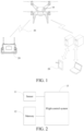
- FIG. 1 is an application environment according to an embodiment of the present invention.
- the application environment is a UAV system.
- the system includes a UAV 10, a remote control device 20 and a wireless network 30.
- the UAV 10 may be a UAV driven by any type of power (such as electricity).
- the UAV includes but is not limited to a four-axis UAV, a fixed-wing aircraft and a helicopter model. In this embodiment, a four-axis UAV is used as an example for description.
- a fuselage body of the UAV 10 may carry a plurality of different functional modules.
- the functional modules may be software modules, hardware modules, or a combination of software and hardware, and are configured to implement a modular device for one or more functions.
- the remote control device 20 may be of any type, such as an RC, and is configured to establish a communicative connection to the UAV to control an apparatus of the UAV.
- the RC may be equipped with one or more different user interaction apparatuses. Based on the user interaction apparatuses, user instructions are collected or information is displayed and fed back to a user to realize interaction between the user and the UAV.
- the interaction apparatuses include but are not limited to a button, a roller, a display screen, a touch screen, a mouse, a speaker and a joystick.
- the remote control device 20 may be equipped with a display screen.
- the display screen receives a remote control instruction of a user for the UAV and displays an aerial image to the user, or presents a corresponding simulated pilot interface to the user.
- One or more flight parameters such as a flight velocity, a heading or a remaining batter level are displayed on the simulated pilot interface.
- the remote control device 20 may be implemented by a smart terminal.
- the smart terminal includes but is not limited to a smart phone, a tablet computer, a laptop computer, and a wearable device.
- the smart terminal establishes a communicative connection to the UAV by running a specially configured APP client or web page to realize a data transmission and reception with the UAV. In this way, the smart terminal is used as the remote control device 20.
- the wireless network 30 may be a wireless communication network configured to establish a data transmission channel between two nodes based on any type of data transmission principle.
- the wireless network may be a Bluetooth network, a Wi-Fi network, a wireless cellular network, or a combination thereof located in a different signal frequency band.
- a specific frequency band or network form of the wireless network 30 is related to a communication device used for the UAV 10 and the remote control device 20.
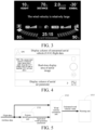
- FIG. 2 is a functional block diagram of the UAV 10 according to an embodiment of the present invention.
- the functional modules carried on the UAV 10 include a plurality of sensors 11, a memory 12 and a flight control system 13.
- the sensors 11 are disposed in the fuselage body and are configured to detect motion status parameters of the UAV during a flight.
- the sensors are six-axis gyroscopes or accelerometers.
- the sensors 11 are fundamental sensors required for design and manufacture of the UAV 10.
- the sensors are configured to monitor a current motion status of the UAV 10 to effectively control the flight of the UAV 10.
- the memory 12 is a non-volatile computer-readable storage medium, such as at least one magnetic disk storage device, a flash memory device or other non-volatile solid-state storage devices.
- the memory has a program storage area and a data storage area respectively configured to store corresponding data information, for example, a non-volatile software program, a non-volatile computer executable program and a module stored in the program storage area, or a calculation result and captured image information stored in the data storage area.
- the flight control system 13 is a core for control of the flight of the UAV. Specifically, the flight control system may use any type of processor.
- the flight control system is used as a core of logic processing and calculation.
- the flight control system 13 is configured to acquire data, perform a logical calculation function, deliver a calculation result, and change a flight state of the UAV 10 according to a user instruction, to ensure that the UAV 10 is in a safe and controllable flight state.
- the flight control system 13 may acquire one or more types of collected data from the sensors 11, and analyze and determine a plurality of pieces of data related to the UAV (such as an attitude angle, an acceleration and a flight velocity) by using a set data fusion or analysis method as a basis for controlling the motion status of the UAV.
- the flight control system 13 is further connected to the memory 12.
- a corresponding software program or computer executable program is called from the memory 12 to perform corresponding logical calculation function, so as to perform corresponding calculation and determination.
- the flight control system 13 may read the data information related to the UAV, estimate current wind interference to the UAV based on the principle of system identification, and output a corresponding estimates wind velocity value. Then the flight control system compares the outputted estimated wind velocity value with a preset warning condition to determine whether a warning signal currently needs to be triggered.
- the UAV 10 feeds back the warning signal to the remote control device 20 by using the wireless network 30.
- the remote control device 20 may display corresponding warning information by using the interaction apparatuses to prompt an operator to pay attention to flight safety and land the UAV at a suitable place in time.
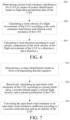
- a display interface shown in FIG. 3 may be used to prompt "Large wind velocity" to the user at a center of a simulated pilot interface.
- prompt information tips
- FIG. 4 prompt information (tips) may be displayed in a partial area of a display screen of the smart terminal.
- a special warning tone is played by using a speaker of the remote control device 20 to warn that the current wind velocity is excessively large.
- the flight control system 13 may further convert the wind velocity of the flight environment of the UAV provided by the wind velocity estimator to wind direction data and provide the wind direction data to the remote control device 20.
- An interaction device such as the display screen of the remote control device 20 may display the wind velocity and the wind direction. In this way, the operator can learn a current wind status in the flight airspace in time.
- FIG. 1 In the application environment shown in FIG. 1 , only the applications of wind velocity observation and warning on the UAV system are shown. Those skilled in the art can understand that the functional module that realizes the wind velocity observation and the warning may be carried on other types of mobile vehicles (such as a remote control vehicle). Data information related to the mobile vehicle is received, and interference to motion of the mobile vehicle is calculated, to realize the warning same as or similar to the above.
- the inventive idea disclosed in the embodiments of the present invention is not limited to being applied to the UAV system shown in FIG. 1 .
- the intensity of interference may be quantitatively observed by detecting changes in an attitude angle of the UAV during hovering.
- the amount of wind interference to the operation of the UAV may alternatively be determined based on the principle of force balance and the principle of interference observation, to estimate the wind velocity born by the UAV.
- FIG. 5 is a functional block diagram of a wind velocity estimator according to an example, that is not part of the claimed invention. As shown in FIG. 5 , the wind velocity estimator includes a system identification unit 1311 and a wind velocity estimation unit 1312.
- the system identification unit 1311 is configured to receive flight data and attribute data of a UAV, and determine current wind resistance interference of the UAV by means of system identification.
- the system identification unit 1311 may be implemented by a processor (such as a flight control system) that can perform logical determination by calling a computer software program instruction related to the system identification pre-stored in a memory.
- the flight data includes an attitude angle, a flight velocity, an acceleration and a flight altitude of the UAV.
- the attribute data includes a mass of the UAV, an inherent wind resistance coefficient and a nonlinear function used to calculate a windward area.
- the system identification unit 1311 quantitatively determines interference to motion of the UAV by means of the system identification.
- main interference to the motion of the UAV is substantially considered to be from the wind in a flight airspace. Therefore, the interference may be equivalently considered as resistance caused by the wind, to calculate the wind resistance interference.
- the system identification unit 1311 uses a system identification model constructed by using some priori knowledge (such as a dynamic velocity change equation of the UAV).
- a to-be-identified parameter may be an equivalent wind resistance coefficient.
- the equivalent wind resistance coefficient is specifically a parameter related to the wind resistance interference.
- the equivalent wind resistance coefficient is used to represent a relationship between the UAV and the wind resistance of the UAV. That is to say, after the equivalent wind resistance coefficient is learned and a plurality of pieces of data related to an attribute (that is, the attribute data) and a motion status (that is, the flight data) of the UAV is acquired by using a sensor of the UAV, a current wind resistance can be calculated.
- the wind velocity estimation unit 1312 is connected to the system identification unit 1311.
- the wind velocity estimation unit receives the wind resistance interference and calculates a wind velocity of a flight environment of the UAV according to changes in inherent wind resistance relative to the UAV.
- the specific wind velocity calculation process may be determined according to a form of inputted wind resistance interference.
- the specific wind velocity calculation process may be completed by using any conversion method.
- the wind velocity estimation unit 1312 may be implemented by a processor (such as a flight control system) that can perform logical determination by calling a computer software program instruction related to wind velocity calculation pre-stored in a memory.
- a processor such as a flight control system
- two directions x and y perpendicular to each other may be constructed on a plane where the UAV is located. Equivalent wind resistance coefficient components and wind velocity components in the two directions may be calculated to complete the wind velocity estimation.
- V ⁇ x is a velocity change rate (that is, acceleration) of the UAV in the direction x.
- V ⁇ y is a velocity change rate of the UAV in the direction y.
- V x is a velocity of the UAV in the direction x.
- V y is a velocity of the UAV in the direction y velocity.
- T is propeller tension.
- ⁇ is a pitch angle.
- ⁇ is a roll angle.
- P is an air density at a flight altitude.
- S fb is a windward area of the UAV during a flight in the direction x.
- S rl is a windward area of the UAV during a flight in the direction y.
- C x is an equivalent wind resistance coefficient component in the direction x.
- C y is an equivalent wind resistance coefficient component in the direction y.
- m is a mass of a UAV.
- w x is a model uncertainty in the direction x.
- w y
- a different altitude has a corresponding air density.
- the air density at the flight altitude of the UAV generally can be acquired by querying a table. Certainly, when the air density changes little, a fixed value may be directly used to ignore the slight change in the air density.
- the model uncertainty is an adjustment part used to compensate for inconsistency between an established system model and an actual motion status.
- the model uncertainty is an empirical value or function, and may be determined and adjusted by using statistical methods such as experiment or data analysis.
- the windward area is a parameter changing with the flight attitude of the UAV.
- the windward area may be approximated as a nonlinear function related to the attitude angle.
- S fb 0 is a windward area of the UAV during the flight in the direction x at an attitude angle of 0.
- S rl 0 is a windward area of the UAV during the flight in the direction y at an attitude angle of 0.
- the propeller tension is related to an output power of a motor, which is externally expressed as the acceleration of the UAV.
- a larger acceleration means larger propeller tension.
- the direction z is perpendicular to a plane formed by the direction x and the direction y.
- the system identification unit 1311 may complete the parameter identification and acquire the current equivalent wind resistance coefficient to reflect the wind resistance interference of the flight environment of the UAV.
- the inherent wind resistance of the UAV is expressed by an inherent wind resistance coefficient of the UAV.
- V wx is a wind velocity component of the wind velocity of the flight environment of the UAV in the direction x.
- V wy is a wind velocity component of the wind velocity of the flight environment of the UAV in the direction y.
- V x is a velocity of the UAV in the direction x,
- V y is a velocity of the UAV in the direction y.
- P is an air density at a flight altitude.
- S fb is a windward area of the UAV during a flight in the direction x.
- S rj is a windward area of the UAV during a flight in the direction y.
- C x is an equivalent wind resistance coefficient component in the direction x.
- C y is an equivalent wind resistance coefficient component in the direction y.
- C dx is an inherent wind resistance coefficient of the UAV in the direction x.
- C dy is an inherent wind resistance coefficient of the UAV in the direction y.
- the inherent wind resistance coefficient is a mathematical parameter determined when the UAV is in a windless environment according to a shape, a structure and the like of the UAV. Specifically, the inherent wind resistance coefficient may be determined by using a data statistics method such as a least square fitting according to a plurality of sets of experimental data collected during a windless indoor flight or a flight in other ideal experimental environments before delivery and sell of the UAV.
- the above method for calculating the inherent wind resistance coefficient is an offline calculation process.
- the process may be completed in advance and stored in the memory of the UAV.
- the process is called by the wind velocity estimation unit 1312 without execution on each UAV.
- required data information related to the UAV includes at least an attitude angle, a flight velocity, an acceleration, a flight altitude, a mass and an inherent wind resistance coefficient of the UAV and a nonlinear function used to calculate a windward area.
- the attitude angle, the flight velocity, the acceleration and the flight altitude of the UAV are all parameters changing with the motion status of the UAV.
- the parameters may be acquired by means of data fusion or the like based on the sampling data collected by a series of basic sensors disposed on the UAV.
- the mass and the inherent wind resistance coefficient of the UAV and the nonlinear function used to calculate the windward area are parameters depending on inherent attributes of the UAV.
- the parameters may be pre-determined by means of offline calculation through experiments and stored in the memory for calling.
- the wind velocity estimator may further include a warning unit 1313.
- the warning unit 1313 is connected to the wind velocity estimation unit 1312.
- the warning unit is configured to receive a wind velocity of a current flight environment provided by the wind velocity estimation unit 1312 and send a warning signal to realize wind velocity warning when the wind velocity of the flight environment of the UAV satisfies a preset warning condition.
- the warning unit 1313 may be implemented by a processor (such as a flight control system) that can perform logical determination by calling a computer software program instruction related to the preset warning condition pre-stored in a memory.
- a processor such as a flight control system
- the system identification unit, the wind velocity estimation unit and the warning unit all can be implemented by the flight control system in the embodiments of the present invention by calling computer software program instructions corresponding to the functions and the steps.
- FIG. 5 describes in detail a structure of the wind velocity estimator provided in the examples by using a functional block diagram as an example.
- Those skilled in the art may selectively use software, hardware, or a combination of software and hardware to implement the function of the wind velocity estimator disclosed in the specification, the steps to be performed, the functions to be implemented and actual requirements (such as chip power consumption, heating restrictions, silicon chip costs or chip volumes).
- using more software can reduce the chip costs and an occupied circuit area and facilitate modification.
- Using more hardware circuits can improve reliability and a calculation velocity.
- an embodiment of the present invention further provides a complete wind velocity measurement method. Therefore, one or more specific steps in the embodiment of the wind velocity calculation method may be applied to the wind velocity estimator. The steps are implemented by corresponding functional modules. For brevity, the description is not repeated herein.
- FIG. 6 is a method flowchart of a wind velocity measurement method according to an embodiment of the present invention.
- the wind velocity measurement method may be performed by the UAV shown in FIG. 1 to acquire wind velocity information of a current flight environment of the UAV.
- the wind velocity measurement method may be implemented by the flight control system shown in FIG. 2 by calling data information provided by a memory and a sensor.
- the method includes the following steps: 601: Determining current wind resistance interference of a UAV by means of system identification based on flight data and attribute data of the UAV.
- interference to an entire motion system is estimated based on the changes in data inputted and outputted by the motion system of the UAV with time (which is all equivalent to wind resistance interference).
- the flight data is data detected in real time and changing with a flight status of the UAV (for example, an attitude angle, a flight velocity, a flight altitude and an acceleration of the UAV).
- the attribute data is preset and depends on inherent attributes of the UAV (such as a mass and an inherent wind resistance coefficient of the UAV and a nonlinear function used to calculate a windward area are parameters).
- the wind resistance interference estimated by means of the system identification is actually caused by constant resistance of the UAV in a windless condition and external wind in a flight airspace.
- the wind velocity of the current flight environment of the UAV may be determined by means of corresponding conversion according to complete changes of the wind resistance interference relative to the inherent wind resistance.
- the wind velocity measurement method further includes the following step:
- a system identification model used for the system identification is a current equivalent wind resistance coefficient of the UAV (construction of the system identification model is an offline construction process).
- the equivalent wind resistance coefficient corresponding to current flight data and the attribute data of the UAV is solved by using an online identification method.
- the equivalent wind resistance coefficient is a mathematical parameter determined by causing all interference to the UAV during motion to be equivalent to the wind interference.
- the equivalent wind resistance coefficient represents a relationship between a current operating status of the UAV and the wind resistance of the UAV.
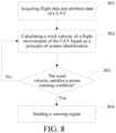
- FIG. 7 is a method flowchart of an online identification method according to an embodiment of the present invention. As shown in FIG. 7 , the online identification method includes the following steps: 701: Discretizing the system identification model to form a corresponding discrete equation.
- Recursive calculation is frequently used in a mathematical operation.
- a target result can be obtained when an initial value and a recurrence relationship between two items are known.
- the equivalent wind resistance means a sum of all resistance of the UAV receives during a flight estimated by means of the system identification. Since resistance of the UAV mainly comes from wind, the resistance all may be equivalent to wind resistance.
- the equivalent wind resistance coefficient is a mathematical parameter related to the wind resistance. Therefore, the equivalent wind resistance coefficient may be determined by means of proper conversion when corresponding flight data and attribute data of the UAV are known.
- the windward area is calculated by using the current attitude angle of the UAV and the nonlinear function used to calculate the windward area.
- the air density is calculated by using a current flight altitude of the UAV.
- x V x or V y
- u ⁇ T sin ⁇ m or T sin ⁇ cos ⁇ m
- c -0.5 C x ⁇ S fb or -0.5 C y ⁇ S rl
- w w x or w y .
- the inherent wind resistance is correspondingly expressed by an inherent wind resistance coefficient of the UAV.
- the wind velocity of the flight environment of the UAV may be specifically calculated by using the formula (5).
- the wind velocity measurement method further includes some offline steps, such as determining an inherent wind resistance coefficient of the UAV in the direction x and an inherent wind resistance coefficient in the direction y, fitting the nonlinear function required to calculate the windward area, and determining the mass of the UAV.
- the offline steps do not need to be repeated on each UAV. Instead, the offline steps are recorded in the memory of the UAV after offline experimental calculation is completed. Further, a UAV having a same or similar shape and structure may directly use the existing data to omit one or more of the above offline steps.
- the wind velocity measurement method provided in this embodiment of the present invention estimates the current wind resistance interference to the UAV and then calculates the wind velocity of the flight environment by means of the parameter identification process through system identification.
- the method neither requires an additional wind velocity or wind sensor, nor relies on a huge database.
- the method requires low implementation costs, has desirable real-time performance, and can be widely applied to UAV systems.
- the flight control system may periodically perform the wind velocity measurement method provided in the embodiments of the present invention according to a set period to obtain an estimated value of a current wind velocity and/or wind direction.
- the flight velocity of the UAV is mainly affected by the wind interference during flight, and impact caused by other interference is relatively small. Therefore, the estimated value of the wind velocity and/or the wind force calculated under the equivalent premise may be substantially considered as accurate and can substantially satisfy use requirements of warning.
- FIG. 8 is a method flowchart of a wind velocity measurement method according to another embodiment of the present invention.
- the method includes the following steps: 801: Acquiring flight data and attribute data of a UAV.
- the flight data and the attribute data that are required to be acquired depend on variables that are required to be inputted for calculating a theoretical flight velocity of the UAV. Those skilled in the art may adjust or change the data information according to an actual requirement, a preference setting or an accuracy requirement.
- the flight data changes with a motion status of the UAV.
- the flight data may be calculated from sampling data of a sensor of the UAV by using a data fusion algorithm.
- the attribute data is an inherent attribute of the UAV.
- the attribute data depends on a structure and the like of the UAV, and does not change with the motion status.
- the flight data may be pre-set and recorded in a memory by means of an experiment and read from the memory when required.
- step 802 the wind velocity of the flight environment of the UAV can be continuously updated to ensure warning in time.
- a specific update period is an empirical value, and may be adjusted or set according to an actual condition, such as 1 minute or longer.
- step 803 Determining whether the wind velocity satisfies a preset warning condition, if yes, perform step 804 is performed, or if no, return to step 802 to update the wind velocity.
- the preset warning condition is a determination standard preset based on experience or an actual condition of the UAV (for example, an ability of the UAV to bear a wind velocity).
- the preset warning condition may be composed of one or more conditions, and are used to measure a probability of uncontrolled accidents of the UAV. That is to say, when the preset warning condition is satisfied, it indicates that the flight control system of the UAV has substantially reached a design upper limit to resist the wind interference, and is very likely to encounter abnormalities or accidents.
- the warning condition may be a preset alarming threshold.
- a monitor 132 may continuously detect whether the wind velocity has reached the alarming threshold. When the wind velocity reaches the alarming threshold, a warning signal is sent to the remote control device 20.
- the alarming threshold is an empirical value, and may be determined or set by technicians by means of experiments or tests according to the specific an operating status of the UAV.
- the warning signal may be represented by an identifier of any suitable form or type.
- a warning mark level is simply represented by using 1 and 0. When a value of the warning mark level is 1, it indicates that a warning signal is sent. When the value of the warning mark level is 0, it indicates that there is no warning signal.
- V wx is a wind velocity in a direction x.
- V wy is a wind velocity in a direction y.
- flag is a value of a mark level of the warning signal. That is to say, when a sum of squares of the wind velocities in the direction x and the direction y is greater than or equal to a square of the preset alarming threshold, the monitor 132 determines that the wind velocity satisfies the preset warning condition and sends a warning signal.
- the determination logic shown in the formula (11) is merely an example and is not intended to limit the working steps of the monitor 132 to send the warning signal. Those skilled in the art may use, according to actual requirements, a different warning condition to determine whether the UAV bears an excessively large wind velocity and whether the aircraft control system cannot be effectively controlled.
- the remote control device 20 may feed back corresponding warning prompt information to a user by using a display screen or other interaction devices, to prompt the user to stop the flight of the UAV in time and land the UAV at a safe and controllable position.
- the specific warning information may be set according to an actual condition.
- a form of the specific warning information includes but is not limited to text or pictures. For example, words such as "The current wind velocity is excessively large” may be highlighted on a display interface of an RC, or a specific color icon may be used to indicate that the current wind velocity exceeding the limit. Further, a voice prompt may alternatively be broadcast by a speaker.
- the flight control system may specifically perform the steps shown in FIG. 9 to achieve wind velocity measurement and warning of the UAV without relying on the wind velocity sensor and the database.
- the direction x and the direction y are two vectors perpendicular to each other in a plane where the UAV is located.
- the direction x is a direction in which the UAV moves forward and backward
- the direction y is a direction in which the UAV flies leftward and rightward.
- the mass of the UAV, the nonlinear functions f fb ( ⁇ , ⁇ ) and f rl ( ⁇ , ⁇ ) of the windward areas in the directions x and y and the attitude angle, the inherent wind resistance coefficient of the UAV in the direction x and the inherent wind resistance coefficient in the direction y are measured and stored in the memory of the UAV.
- the initial values required for the recursive calculation may be set or initialized according to an actual condition.
- the initial values may all be initialized to 0.
- FIG. 10 is a graph showing changes of a wind velocity with time according to an embodiment of the present invention.
- the wind velocity components in the direction x and the direction y may be calculated, and the corresponding two components are combined into the current wind velocity born by the UAV, and a curve of the wind velocity changing with time may be obtained.
- the determination logic is to determine whether a warning signal is required to be sent by using the alarming threshold as a determination condition.
- the alarming threshold is a preset empirical value. When the wind velocity is higher than the alarming value, an alarming signal is sent. The alarming signal indicates that the wind is currently relatively large and prompts a user or an operator to be careful.
- the wind velocity is required to be updated periodically.
- the method has a desirable application prospect.
Landscapes
- Engineering & Computer Science (AREA)
- Physics & Mathematics (AREA)
- General Physics & Mathematics (AREA)
- Aviation & Aerospace Engineering (AREA)
- Radar, Positioning & Navigation (AREA)
- Remote Sensing (AREA)
- Automation & Control Theory (AREA)
- Control Of Position, Course, Altitude, Or Attitude Of Moving Bodies (AREA)
Claims (14)
- Windgeschwindigkeitsmessverfahren, das von einem unbemannten Luftfahrzeug, unmanned aerial vehicle - UAV (10), durchgeführt wird, umfassend:Bestimmen der aktuellen Windwiderstandsbeeinträchtigung (601) des UAV (10) mittels Systemidentifizierung auf der Grundlage von Flugdaten und beschreibenden Daten des UAV (10), wobei die Flugdaten einen Lagewinkel, eine Fluggeschwindigkeit, eine Beschleunigung und eine Flughöhe des UAV (10) umfassen und die beschreibenden Daten ein Gewicht des UAV (10), einen inhärenten Windwiderstandskoeffizienten und eine nichtlineare Funktion zum Berechnen einer dem Wind zugewandten Fläche umfassen, wobei die dem Wind zugewandte Fläche unter Verwendung der nichtlinearen Funktion in Bezug auf einen aktuellen Lagewinkel des UAV (10) berechnet wird; undBerechnen einer Windgeschwindigkeit (602) einer Flugumgebung des UAV (10) gemäß der Windwiderstandsbeeinträchtigung und dem inhärenten Windwiderstand des UAV (10).
- Windgeschwindigkeitsmessverfahren nach Anspruch 1, wobei das Bestimmen der aktuellen Windwiderstandsbeeinträchtigung (601) eines UAV (10) mittels Systemidentifizierung auf der Grundlage von Flugdaten und beschreibenden Daten des UAV (10) Folgendes umfasst:Erstellen eines Systemidentifizierungsmodells des UAV (10), wobei ein festzustellender Parameter des Systemidentifizierungsmodells ein aktueller äquivalenter Windwiderstandskoeffizient des UAV (10) ist; undLösen des entsprechenden äquivalenten Windwiderstandskoeffizienten gemäß aktuellen Flugdaten und den beschreibenden Daten des UAV (10) unter Verwendung eines Online-Identifizierungsverfahrens; undwobei das Berechnen einer Windgeschwindigkeit einer Flugumgebung des UAV (10) gemäß der Windwiderstandsbeeinträchtigung und dem inhärenten Windwiderstand des UAV (10) Folgendes umfasst:
Berechnen der Windgeschwindigkeit der Flugumgebung des UAV (10) gemäß einem Unterschied zwischen dem äquivalenten Windwiderstandskoeffizienten und dem inhärenten Windwiderstandskoeffizienten des UAV (10). - Windgeschwindigkeitsmessverfahren nach Anspruch 2, wobei das Lösen des entsprechenden äquivalenten Windwiderstandskoeffizienten gemäß aktuellen Flugdaten und den beschreibenden Daten des UAV (10) unter Verwendung eines Online-Identifizierungsverfahrens Folgendes umfasst:Diskretisieren des Systemidentifizierungsmodells (701) zum Erstellen einer entsprechenden diskreten Gleichung;rekursives Berechnen eines äquivalenten Windwiderstands (702) des UAV (10) gemäß einem voreingestellten Ausgangswert, dem aktuellen Lagewinkel, einer aktuellen Fluggeschwindigkeit und einer aktuellen Beschleunigung des UAV (10); undUmwandeln des äquivalenten Windwiderstands (703) in einen äquivalenten Windwiderstandskoeffizienten gemäß einer aktuellen dem Wind zugewandten Fläche des UAV (10) und einer Luftdichte, wobei die Luftdichte unter Verwendung einer aktuellen Flughöhe des UAV (10) berechnet wird.
- Windgeschwindigkeitsmessverfahren nach Anspruch 2, wobei der äquivalente Windwiderstandskoeffizient durch eine Komponente des äquivalenten Windwiderstandskoeffizienten in einer Richtung x und eine Komponente des äquivalenten Windwiderstandskoeffizienten in einer Richtung y wiedergegeben ist und die Windgeschwindigkeit durch eine Windgeschwindigkeitskomponente in der Richtung x und eine Windgeschwindigkeitskomponente in der Richtung y wiedergegeben ist, wobei die Richtung x und die Richtung y senkrecht zueinander verlaufen und sich auf derselben Ebene wie das UAV (10) befinden.
- Windgeschwindigkeitsmessverfahren nach Anspruch 4, wobei das Berechnen der Windgeschwindigkeit der Flugumgebung des UAV (10) gemäß einem Unterschied zwischen dem äquivalenten Windwiderstandskoeffizienten und dem inhärenten Windwiderstandskoeffizienten des UAV (10) insbesondere Folgendes umfasst:Berechnen der Windgeschwindigkeit der Flugumgebung des UAV (10) unter Verwendung der folgenden Formel:
 in der Vwx eine Windgeschwindigkeitskomponente der Windgeschwindigkeit der Flugumgebung des UAV (10) in einer Richtung x ist, Vwy eine Windgeschwindigkeitskomponente der Windgeschwindigkeit der Flugumgebung des UAV (10) in einer Richtung y ist, Vx eine Geschwindigkeit des UAV (10) in der Richtung x ist, Vy , eine Geschwindigkeit des UAV (10) in der Richtung y ist, ρ eine Luftdichte in einer Flughöhe ist, Sfb eine dem Wind zugewandte Fläche des UAV (10) während eines Flugs in der Richtung x ist, Srl eine dem Wind zugewandte Fläche des UAV (10) während eines Flugs in der Richtung y ist, Cx eine Komponente des äquivalenten Windwiderstandskoeffizienten in der Richtung x ist, Cy eine Komponente des äquivalenten Windwiderstandskoeffizienten in der Richtung y ist, Cdx ein inhärenter Windwiderstandskoeffizient des UAV (10) in der Richtung x ist und Cdy ein inhärenter Windwiderstandskoeffizient des UAV (10) in der Richtung y ist.
 - Windgeschwindigkeitsmessverfahren nach Anspruch 5, wobei der inhärente Windwiderstandskoeffizient des UAV (10) in der Richtung x und der inhärente Windwiderstandskoeffizient in der Richtung y mittels der Methode der kleinsten Quadrate gemäß Flugdaten des UAV (10) in einem windstillen Raum bestimmt werden.
- Windgeschwindigkeitsmessverfahren nach Anspruch 4, wobei das Systemidentifizierungsmodell durch die folgende Formel wiedergegeben ist:
 in der V̇x eine Beschleunigung des UAV (10) in der Richtung x ist, V̇ y eine Beschleunigung des UAV (10) in der Richtung y ist, Vx eine Geschwindigkeit des UAV (10) in der Richtung x ist, Vy eine Geschwindigkeit des UAV (10) in der Richtung y ist,T die Propeller-Zugspannung ist, θ ein Nickwinkel ist, φ ein Rollwinkel ist, ρ eine Luftdichte bei einer Flughöhe ist, Sfb eine dem Wind zugewandte Fläche des UAV (10) während eines Flugs in der Richtung x ist, Srl eine dem Wind zugewandte Fläche des UAV (10) während eines Flugs in der Richtung y ist, C x die Komponente des äquivalenten Windwiderstandskoeffizienten in der Richtung x ist, Cy die Komponente des äquivalenten Windwiderstandskoeffizienten in der Richtung y ist, m die Masse des UAV (10) ist, wx eine Modellunsicherheit in der Richtung x ist und wy eine Modellunsicherheit in der Richtung y ist.
 - Windgeschwindigkeitsmessverfahren nach Anspruch 5 oder 7, wobei die dem Wind zugewandte Fläche unter Verwendung der folgenden Formel berechnet wird:


- Windgeschwindigkeitsmessverfahren nach Anspruch 7, wobei die Propeller-Zugspannung unter Verwendung der folgenden Formel berechnet wird:

- Windgeschwindigkeitsmessverfahren nach Anspruch 7, ferner umfassend:
Berechnen einer Windrichtung (603) gemäß den Windgeschwindigkeitskomponenten in der Richtung x und der Richtung y unter Verwendung der folgenden Formel:
in der ψ ein Gierwinkel des UAV (10) ist, β die Windrichtung ist, Vwx die Windgeschwindigkeitskomponente in der Richtung x ist und Vwy die Windgeschwindigkeitskomponente in der Richtung y ist. - Windgeschwindigkeitsmessverfahren nach einem der Ansprüche 1 bis 10, ferner umfassend:
Senden eines Warnsignals (804), wenn die Windgeschwindigkeit der Flugumgebung des UAV (10) eine voreingestellte Warnbedingung erfüllt. - Windgeschwindigkeitsmessverfahren nach Anspruch 11, wobei das Senden eines Warnsignals (804), wenn die Windgeschwindigkeit der Flugumgebung des UAV (10) eine voreingestellte Warnbedingung erfüllt, Folgendes umfasst:
Bestimmen, ob die voreingestellte Warnbedingung erfüllt ist, mittels einer Berechnung unter Verwendung der folgenden Formel: in der Vwx die Windgeschwindigkeitskomponente in der Richtung x ist, Vwy die Windgeschwindigkeitskomponente in der Richtung y ist und Vthr ein sicherer Schwellenwert der Windgeschwindigkeit ist;Senden des Warnsignals, wenn die voreingestellte Warnbedingung erfüllt ist, undFortsetzen des Erfassens der Windgeschwindigkeit der Flugumgebung des UAV (10), wenn die voreingestellte Warnbedingung nicht erfüllt ist.
 - Unbemanntes Luftfahrzeug, unmanned aerial vehicle - UAV (10), umfassend: einen Rumpfkörper und eine Mehrzahl von Sensoren (11), einen Speicher (12) und ein Flugsteuerungssystem (13), das an dem Rumpfkörper angeordnet ist, wobei der Speicher (12) eine von einem Computer ausführbare Programmanweisung speichert, wobei die von einem Computer ausführbare Programmanweisung bei Abruf durch das Flugsteuerungssystem (13) bewirkt, dass das Flugsteuerungssystem (13) Flugdaten von den Sensoren (11) abruft, beschreibende Daten aus dem Speicher (12) abruft und das Windgeschwindigkeitsmessverfahren nach einem der Ansprüche 1 bis 12 durchführt.
- UAV (10) nach Anspruch 13, wobei das Flugsteuerungssystem (13) ferner dazu ausgestaltet ist, eine Windgeschwindigkeit einer Flugumgebung des UAV (10) in eine Windrichtung umzuwandeln und die Windgeschwindigkeit und die Windrichtung auf einer Fernsteuerungsvorrichtung (20), die dem UAV (10) entspricht, anzuzeigen.
Applications Claiming Priority (2)
| Application Number | Priority Date | Filing Date | Title |
|---|---|---|---|
| CN201910682355.6A CN110427047B (zh) | 2019-07-26 | 2019-07-26 | 风速测算方法、风速估算器及无人机 |
| PCT/CN2020/104585 WO2021018050A1 (zh) | 2019-07-26 | 2020-07-24 | 风速测算方法、风速估算器及无人机 |
Publications (3)
| Publication Number | Publication Date |
|---|---|
| EP4006683A1 EP4006683A1 (de) | 2022-06-01 |
| EP4006683A4 EP4006683A4 (de) | 2022-08-24 |
| EP4006683B1 true EP4006683B1 (de) | 2024-12-25 |
Family
ID=68412674
Family Applications (1)
| Application Number | Title | Priority Date | Filing Date |
|---|---|---|---|
| EP20846707.6A Active EP4006683B1 (de) | 2019-07-26 | 2020-07-24 | Windgeschwindigkeitsmess- und -berechnungsverfahren, windgeschwindigkeitsschätzer und unbemanntes luftfahrzeug |
Country Status (4)
| Country | Link |
|---|---|
| US (1) | US20220146546A1 (de) |
| EP (1) | EP4006683B1 (de) |
| CN (2) | CN114967736B (de) |
| WO (1) | WO2021018050A1 (de) |
Families Citing this family (27)
| Publication number | Priority date | Publication date | Assignee | Title |
|---|---|---|---|---|
| CN114967736B (zh) * | 2019-07-26 | 2025-09-02 | 深圳市道通智能航空技术股份有限公司 | 风速测算方法、风速估算器及无人机 |
| CN113188541B (zh) * | 2020-01-14 | 2025-04-01 | 广州极飞科技股份有限公司 | 获取无人机的空速的方法、装置、存储介质及处理器 |
| CN111544797A (zh) * | 2020-04-02 | 2020-08-18 | 峰飞国际有限公司 | 一种应用于无人机的高空抛投瞄准方法及系统、存储介质 |
| WO2021217303A1 (zh) * | 2020-04-26 | 2021-11-04 | 深圳市大疆创新科技有限公司 | 控制无人机的方法、装置和无人机 |
| CN112462798B (zh) * | 2020-12-04 | 2021-05-28 | 三生万物(北京)人工智能技术有限公司 | 一种无人机及提高无人机航线飞行性能的方法 |
| CN112230671B (zh) * | 2020-12-13 | 2021-03-16 | 深圳联和智慧科技有限公司 | 一种基于智慧灯杆的无人机返航监控方法及控制中心 |
| CN112731957B (zh) * | 2021-04-06 | 2021-09-07 | 北京三快在线科技有限公司 | 无人机的控制方法、装置、计算机可读存储介质及无人机 |
| CN115343500B (zh) | 2021-05-12 | 2024-07-26 | 中光电智能机器人股份有限公司 | 风速检测系统以及风速检测方法 |
| TWI779602B (zh) * | 2021-05-12 | 2022-10-01 | 中光電智能機器人股份有限公司 | 風速檢測系統以及風速檢測方法 |
| CN113359472B (zh) * | 2021-07-02 | 2024-04-19 | 北京理工大学 | 一种四旋翼无人机自适应鲁棒轨迹跟踪控制方法 |
| CN114113671B (zh) * | 2021-11-24 | 2024-03-22 | 国家电投集团广西灵川风电有限公司 | 一种基于多旋翼无人机的高时空分辨率测风系统及测风方法 |
| US20230195116A1 (en) * | 2021-12-17 | 2023-06-22 | Honeywell International Inc. | Apparatuses, computer-implemented methods, and computer program products for generating intuitive data indicators for vehicle user interfaces |
| CN115063474B (zh) * | 2022-06-15 | 2024-03-05 | 新疆大学 | 一种树木迎风面积计算方法及系统 |
| US12164308B2 (en) | 2022-07-15 | 2024-12-10 | Wing Aviation Llc | Tether-based wind estimation |
| CN115683544A (zh) * | 2022-10-31 | 2023-02-03 | 北京唯思德科技有限公司 | 无人机旋翼扰动校正方法及装置 |
| CN115728508B (zh) * | 2022-11-02 | 2025-07-18 | 西安邮电大学 | 一种风速风向测量方法及装置 |
| CN115984459B (zh) * | 2022-12-14 | 2026-03-24 | 金川集团镍钴股份有限公司 | 一种巷道调风方法 |
| CN115791075B (zh) * | 2022-12-28 | 2025-07-22 | 亿航智能设备(广州)有限公司 | 多旋翼风阻系数标定方法、设备及计算机可读存储介质 |
| CN115688288B (zh) * | 2023-01-05 | 2023-04-07 | 西北工业大学 | 飞行器气动参数辨识方法、装置、计算机设备及存储介质 |
| CN116227384A (zh) * | 2023-03-10 | 2023-06-06 | 辽宁工程技术大学 | 一种基于智能通风要求的井下风门建模方法 |
| CN116793630A (zh) * | 2023-05-24 | 2023-09-22 | 岚图汽车科技有限公司 | 基于驾驶环境的汽车风阻系数预测方法、系统及设备 |
| CN116561488B (zh) * | 2023-07-11 | 2023-10-03 | 中国空气动力研究与发展中心低速空气动力研究所 | 一种旋翼配平参数匹配方法 |
| CN116907282B (zh) * | 2023-09-14 | 2024-01-05 | 杭州牧星科技有限公司 | 基于人工智能算法的无人靶机超低空飞行控制方法 |
| CN119105525A (zh) * | 2024-09-05 | 2024-12-10 | 深圳市士翰科技有限责任公司 | 基于倾转式垂直起降的飞行器控制方法及系统 |
| CN119376418B (zh) * | 2024-12-11 | 2025-04-22 | 深圳市博坦智能有限公司 | 风况预测方法、风况提示方法、无人飞行器及控制终端 |
| CN120371005B (zh) * | 2025-04-23 | 2025-12-02 | 南京拓恒无人系统研究院有限公司 | 基于智能传感器的无人机飞控数据采集控制系统及方法 |
| CN120470205A (zh) * | 2025-07-11 | 2025-08-12 | 南方科技大学 | 基于无人机姿态变化的风速风向估算方法、装置、无人机设备及存储介质 |
Family Cites Families (19)
| Publication number | Priority date | Publication date | Assignee | Title |
|---|---|---|---|---|
| US8219267B2 (en) * | 2010-05-27 | 2012-07-10 | Honeywell International Inc. | Wind estimation for an unmanned aerial vehicle |
| CN102520726B (zh) * | 2011-12-19 | 2013-07-03 | 南京航空航天大学 | 大攻角飞行状态下的大气攻角及侧滑角估计方法 |
| US20140046510A1 (en) * | 2012-08-13 | 2014-02-13 | Lockheed Martin Corporation | Estimating a wind vector |
| US9208687B2 (en) * | 2013-01-15 | 2015-12-08 | Raytheon Canada Limited | System and method for social networking of aircraft for information exchange |
| US8914164B1 (en) * | 2013-08-02 | 2014-12-16 | Honeywell International Inc. | System and method for computing mach number and true airspeed |
| US10338090B2 (en) * | 2014-09-04 | 2019-07-02 | Sikorsky Aircraft Corporation | Airspeed estimation system |
| US10012667B2 (en) * | 2014-10-16 | 2018-07-03 | The Boeing Company | Methods and systems for airborne vehicle wind depiction |
| CN104747224B (zh) * | 2015-01-28 | 2017-02-01 | 西安科技大学 | 一种基于矿井通风等效面积的通风难易程度分析方法 |
| US10023323B1 (en) * | 2015-04-29 | 2018-07-17 | X Development Llc | Estimating wind from an airborne vehicle |
| CN108369243B (zh) * | 2015-12-07 | 2020-09-18 | 乐天株式会社 | 风估计系统、风估计方法以及程序 |
| GB2548899A (en) * | 2016-04-01 | 2017-10-04 | Wind Farm Analytics Ltd | Fluid measurement system for buildings and vehicles |
| CN105929192B (zh) * | 2016-04-13 | 2018-10-30 | 中国电子科技集团公司第五十四研究所 | 一种基于gnss自主测速的测风装置及测风方法 |
| DE102016119152B4 (de) * | 2016-10-07 | 2018-12-27 | Deutsches Zentrum für Luft- und Raumfahrt e.V. | Windmessung mittels eines Multikopters |
| EP3676617A4 (de) * | 2017-09-27 | 2020-08-12 | SZ DJI Technology Co., Ltd. | System und verfahren zur bestimmung der luftgeschwindigkeit |
| JP7054507B2 (ja) * | 2017-11-17 | 2022-04-14 | 国立大学法人金沢大学 | 計測装置、移動体、及び計測方法 |
| CN108196573A (zh) * | 2017-12-29 | 2018-06-22 | 南京奇蛙智能科技有限公司 | 一种无人机在线辨识与控制方法 |
| US10773800B2 (en) * | 2018-07-26 | 2020-09-15 | RSQ-Systems SPRL | Vehicle-based deployment of a tethered surveillance drone |
| CN109374924A (zh) * | 2018-10-25 | 2019-02-22 | 西北工业大学 | 一种基于四旋翼无人机倾斜角的横侧向风场估计方法 |
| CN114967736B (zh) * | 2019-07-26 | 2025-09-02 | 深圳市道通智能航空技术股份有限公司 | 风速测算方法、风速估算器及无人机 |
-
2019
- 2019-07-26 CN CN202210521445.9A patent/CN114967736B/zh active Active
- 2019-07-26 CN CN201910682355.6A patent/CN110427047B/zh active Active
-
2020
- 2020-07-24 WO PCT/CN2020/104585 patent/WO2021018050A1/zh not_active Ceased
- 2020-07-24 EP EP20846707.6A patent/EP4006683B1/de active Active
-
2022
- 2022-01-24 US US17/582,216 patent/US20220146546A1/en not_active Abandoned
Also Published As
| Publication number | Publication date |
|---|---|
| US20220146546A1 (en) | 2022-05-12 |
| EP4006683A1 (de) | 2022-06-01 |
| EP4006683A4 (de) | 2022-08-24 |
| CN114967736A (zh) | 2022-08-30 |
| CN114967736B (zh) | 2025-09-02 |
| WO2021018050A1 (zh) | 2021-02-04 |
| CN110427047A (zh) | 2019-11-08 |
| CN110427047B (zh) | 2022-06-03 |
Similar Documents
| Publication | Publication Date | Title |
|---|---|---|
| EP4006683B1 (de) | Windgeschwindigkeitsmess- und -berechnungsverfahren, windgeschwindigkeitsschätzer und unbemanntes luftfahrzeug | |
| CN110244753B (zh) | 风速测算方法及无人机 | |
| US10909864B2 (en) | Drone obstacle avoidance using real-time wind estimation | |
| US11919637B2 (en) | Automatic return method, apparatus and unmanned aerial vehicle | |
| KR102837990B1 (ko) | 적응형 감지 및 회피 시스템 | |
| CN110658831B (zh) | 对地高度校正方法及装置、无人飞行器 | |
| US20170297736A1 (en) | Methods for situational awareness during formation flight | |
| US20210181766A1 (en) | Return flight control method and device, and unmanned aerial vehicle | |
| CN115113636B (zh) | 控制航空器自主降落至舰船的方法、系统、存储介质及计算设备 | |
| CN108700882A (zh) | 飞行控制方法及装置、监测方法及装置、存储介质 | |
| CN109901387B (zh) | 一种航空器自动近地防撞系统自适应飞行轨迹预测方法 | |
| JP2025023097A (ja) | 非線形電源能力判定 | |
| WO2018110634A1 (ja) | 無人航空機の飛行管理システム、及び飛行管理方法 | |
| CN108153332A (zh) | 基于大包线博弈策略的轨迹模拟系统 | |
| KR20230148625A (ko) | 무인 비행체의 비행 제어 장치 및 그의 동작 방법 | |
| WO2020087297A1 (zh) | 一种无人机测试方法、设备及存储介质 | |
| Banerjee et al. | Probability of Obstacle Collision for UAVs in presence of Wind | |
| CN108089597A (zh) | 基于地面站对无人机进行控制的方法及装置 | |
| CN119717872B (zh) | 一种基于智能化信息数据分析的低空航行器姿态控制系统 | |
| Liu et al. | The altitude hold algorithm of UAV based on millimeter wave radar sensors | |
| US11948467B2 (en) | System, device and method for measuring atmospheric conditions | |
| CN118980375A (zh) | 一种微纳无人机集群互定位方法、装置 | |
| US11046451B1 (en) | Angle of attack estimation system and method | |
| US11292606B1 (en) | Systems and methods of airspeed control with dynamic asymmetric airspeed reference | |
| CN120540351B (zh) | 飞行控制方法、装置、设备、存储介质及产品 |
Legal Events
| Date | Code | Title | Description |
|---|---|---|---|
| STAA | Information on the status of an ep patent application or granted ep patent |
Free format text: STATUS: THE INTERNATIONAL PUBLICATION HAS BEEN MADE |
|
| PUAI | Public reference made under article 153(3) epc to a published international application that has entered the european phase |
Free format text: ORIGINAL CODE: 0009012 |
|
| STAA | Information on the status of an ep patent application or granted ep patent |
Free format text: STATUS: REQUEST FOR EXAMINATION WAS MADE |
|
| 17P | Request for examination filed |
Effective date: 20220216 |
|
| AK | Designated contracting states |
Kind code of ref document: A1 Designated state(s): AL AT BE BG CH CY CZ DE DK EE ES FI FR GB GR HR HU IE IS IT LI LT LU LV MC MK MT NL NO PL PT RO RS SE SI SK SM TR |
|
| A4 | Supplementary search report drawn up and despatched |
Effective date: 20220726 |
|
| RIC1 | Information provided on ipc code assigned before grant |
Ipc: B64C 39/02 20060101ALI20220720BHEP Ipc: G01P 5/02 20060101ALI20220720BHEP Ipc: G05D 1/02 20200101AFI20220720BHEP |
|
| DAV | Request for validation of the european patent (deleted) | ||
| DAX | Request for extension of the european patent (deleted) | ||
| REG | Reference to a national code |
Ref legal event code: R079 Free format text: PREVIOUS MAIN CLASS: G05D0001100000 Ipc: G01P0005020000 Ref country code: DE Ref legal event code: R079 Ref document number: 602020043798 Country of ref document: DE Free format text: PREVIOUS MAIN CLASS: G05D0001100000 Ipc: G01P0005020000 |
|
| GRAJ | Information related to disapproval of communication of intention to grant by the applicant or resumption of examination proceedings by the epo deleted |
Free format text: ORIGINAL CODE: EPIDOSDIGR1 |
|
| GRAP | Despatch of communication of intention to grant a patent |
Free format text: ORIGINAL CODE: EPIDOSNIGR1 |
|
| STAA | Information on the status of an ep patent application or granted ep patent |
Free format text: STATUS: GRANT OF PATENT IS INTENDED |
|
| GRAP | Despatch of communication of intention to grant a patent |
Free format text: ORIGINAL CODE: EPIDOSNIGR1 |
|
| GRAJ | Information related to disapproval of communication of intention to grant by the applicant or resumption of examination proceedings by the epo deleted |
Free format text: ORIGINAL CODE: EPIDOSDIGR1 |
|
| GRAP | Despatch of communication of intention to grant a patent |
Free format text: ORIGINAL CODE: EPIDOSNIGR1 |
|
| GRAJ | Information related to disapproval of communication of intention to grant by the applicant or resumption of examination proceedings by the epo deleted |
Free format text: ORIGINAL CODE: EPIDOSDIGR1 |
|
| GRAJ | Information related to disapproval of communication of intention to grant by the applicant or resumption of examination proceedings by the epo deleted |
Free format text: ORIGINAL CODE: EPIDOSDIGR1 |
|
| GRAP | Despatch of communication of intention to grant a patent |
Free format text: ORIGINAL CODE: EPIDOSNIGR1 |
|
| GRAP | Despatch of communication of intention to grant a patent |
Free format text: ORIGINAL CODE: EPIDOSNIGR1 |
|
| GRAJ | Information related to disapproval of communication of intention to grant by the applicant or resumption of examination proceedings by the epo deleted |
Free format text: ORIGINAL CODE: EPIDOSDIGR1 |
|
| GRAP | Despatch of communication of intention to grant a patent |
Free format text: ORIGINAL CODE: EPIDOSNIGR1 |
|
| RIC1 | Information provided on ipc code assigned before grant |
Ipc: B64U 101/00 20230101ALN20240610BHEP Ipc: G05D 1/00 20060101ALI20240610BHEP Ipc: G01P 5/02 20060101AFI20240610BHEP |
|
| INTG | Intention to grant announced |
Effective date: 20240627 |
|
| INTG | Intention to grant announced |
Effective date: 20240627 |
|
| INTG | Intention to grant announced |
Effective date: 20240709 |
|
| INTG | Intention to grant announced |
Effective date: 20240718 |
|
| INTG | Intention to grant announced |
Effective date: 20240718 |
|
| GRAS | Grant fee paid |
Free format text: ORIGINAL CODE: EPIDOSNIGR3 |
|
| GRAA | (expected) grant |
Free format text: ORIGINAL CODE: 0009210 |
|
| STAA | Information on the status of an ep patent application or granted ep patent |
Free format text: STATUS: THE PATENT HAS BEEN GRANTED |
|
| AK | Designated contracting states |
Kind code of ref document: B1 Designated state(s): AL AT BE BG CH CY CZ DE DK EE ES FI FR GB GR HR HU IE IS IT LI LT LU LV MC MK MT NL NO PL PT RO RS SE SI SK SM TR |
|
| REG | Reference to a national code |
Ref country code: GB Ref legal event code: FG4D |
|
| REG | Reference to a national code |
Ref country code: CH Ref legal event code: EP |
|
| REG | Reference to a national code |
Ref country code: DE Ref legal event code: R096 Ref document number: 602020043798 Country of ref document: DE |
|
| REG | Reference to a national code |
Ref country code: IE Ref legal event code: FG4D |
|
| REG | Reference to a national code |
Ref country code: LT Ref legal event code: MG9D |
|
| PG25 | Lapsed in a contracting state [announced via postgrant information from national office to epo] |
Ref country code: HR Free format text: LAPSE BECAUSE OF FAILURE TO SUBMIT A TRANSLATION OF THE DESCRIPTION OR TO PAY THE FEE WITHIN THE PRESCRIBED TIME-LIMIT Effective date: 20241225 |
|
| PG25 | Lapsed in a contracting state [announced via postgrant information from national office to epo] |
Ref country code: FI Free format text: LAPSE BECAUSE OF FAILURE TO SUBMIT A TRANSLATION OF THE DESCRIPTION OR TO PAY THE FEE WITHIN THE PRESCRIBED TIME-LIMIT Effective date: 20241225 |
|
| PG25 | Lapsed in a contracting state [announced via postgrant information from national office to epo] |
Ref country code: BG Free format text: LAPSE BECAUSE OF FAILURE TO SUBMIT A TRANSLATION OF THE DESCRIPTION OR TO PAY THE FEE WITHIN THE PRESCRIBED TIME-LIMIT Effective date: 20241225 |
|
| PG25 | Lapsed in a contracting state [announced via postgrant information from national office to epo] |
Ref country code: NO Free format text: LAPSE BECAUSE OF FAILURE TO SUBMIT A TRANSLATION OF THE DESCRIPTION OR TO PAY THE FEE WITHIN THE PRESCRIBED TIME-LIMIT Effective date: 20250325 |
|
| PG25 | Lapsed in a contracting state [announced via postgrant information from national office to epo] |
Ref country code: GR Free format text: LAPSE BECAUSE OF FAILURE TO SUBMIT A TRANSLATION OF THE DESCRIPTION OR TO PAY THE FEE WITHIN THE PRESCRIBED TIME-LIMIT Effective date: 20250326 Ref country code: LV Free format text: LAPSE BECAUSE OF FAILURE TO SUBMIT A TRANSLATION OF THE DESCRIPTION OR TO PAY THE FEE WITHIN THE PRESCRIBED TIME-LIMIT Effective date: 20241225 |
|
| PG25 | Lapsed in a contracting state [announced via postgrant information from national office to epo] |
Ref country code: RS Free format text: LAPSE BECAUSE OF FAILURE TO SUBMIT A TRANSLATION OF THE DESCRIPTION OR TO PAY THE FEE WITHIN THE PRESCRIBED TIME-LIMIT Effective date: 20250325 |
|
| REG | Reference to a national code |
Ref country code: NL Ref legal event code: MP Effective date: 20241225 |
|
| PG25 | Lapsed in a contracting state [announced via postgrant information from national office to epo] |
Ref country code: NL Free format text: LAPSE BECAUSE OF FAILURE TO SUBMIT A TRANSLATION OF THE DESCRIPTION OR TO PAY THE FEE WITHIN THE PRESCRIBED TIME-LIMIT Effective date: 20241225 |
|
| REG | Reference to a national code |
Ref country code: AT Ref legal event code: MK05 Ref document number: 1754583 Country of ref document: AT Kind code of ref document: T Effective date: 20241225 |
|
| PG25 | Lapsed in a contracting state [announced via postgrant information from national office to epo] |
Ref country code: SM Free format text: LAPSE BECAUSE OF FAILURE TO SUBMIT A TRANSLATION OF THE DESCRIPTION OR TO PAY THE FEE WITHIN THE PRESCRIBED TIME-LIMIT Effective date: 20241225 |
|
| PG25 | Lapsed in a contracting state [announced via postgrant information from national office to epo] |
Ref country code: PL Free format text: LAPSE BECAUSE OF FAILURE TO SUBMIT A TRANSLATION OF THE DESCRIPTION OR TO PAY THE FEE WITHIN THE PRESCRIBED TIME-LIMIT Effective date: 20241225 |
|
| PG25 | Lapsed in a contracting state [announced via postgrant information from national office to epo] |
Ref country code: ES Free format text: LAPSE BECAUSE OF FAILURE TO SUBMIT A TRANSLATION OF THE DESCRIPTION OR TO PAY THE FEE WITHIN THE PRESCRIBED TIME-LIMIT Effective date: 20241225 |
|
| PG25 | Lapsed in a contracting state [announced via postgrant information from national office to epo] |
Ref country code: IS Free format text: LAPSE BECAUSE OF FAILURE TO SUBMIT A TRANSLATION OF THE DESCRIPTION OR TO PAY THE FEE WITHIN THE PRESCRIBED TIME-LIMIT Effective date: 20250425 |
|
| PG25 | Lapsed in a contracting state [announced via postgrant information from national office to epo] |
Ref country code: PT Free format text: LAPSE BECAUSE OF FAILURE TO SUBMIT A TRANSLATION OF THE DESCRIPTION OR TO PAY THE FEE WITHIN THE PRESCRIBED TIME-LIMIT Effective date: 20250428 |
|
| PG25 | Lapsed in a contracting state [announced via postgrant information from national office to epo] |
Ref country code: EE Free format text: LAPSE BECAUSE OF FAILURE TO SUBMIT A TRANSLATION OF THE DESCRIPTION OR TO PAY THE FEE WITHIN THE PRESCRIBED TIME-LIMIT Effective date: 20241225 |
|
| PG25 | Lapsed in a contracting state [announced via postgrant information from national office to epo] |
Ref country code: RO Free format text: LAPSE BECAUSE OF FAILURE TO SUBMIT A TRANSLATION OF THE DESCRIPTION OR TO PAY THE FEE WITHIN THE PRESCRIBED TIME-LIMIT Effective date: 20241225 Ref country code: AT Free format text: LAPSE BECAUSE OF FAILURE TO SUBMIT A TRANSLATION OF THE DESCRIPTION OR TO PAY THE FEE WITHIN THE PRESCRIBED TIME-LIMIT Effective date: 20241225 |
|
| PG25 | Lapsed in a contracting state [announced via postgrant information from national office to epo] |
Ref country code: SK Free format text: LAPSE BECAUSE OF FAILURE TO SUBMIT A TRANSLATION OF THE DESCRIPTION OR TO PAY THE FEE WITHIN THE PRESCRIBED TIME-LIMIT Effective date: 20241225 |
|
| PG25 | Lapsed in a contracting state [announced via postgrant information from national office to epo] |
Ref country code: CZ Free format text: LAPSE BECAUSE OF FAILURE TO SUBMIT A TRANSLATION OF THE DESCRIPTION OR TO PAY THE FEE WITHIN THE PRESCRIBED TIME-LIMIT Effective date: 20241225 |
|
| PG25 | Lapsed in a contracting state [announced via postgrant information from national office to epo] |
Ref country code: IT Free format text: LAPSE BECAUSE OF FAILURE TO SUBMIT A TRANSLATION OF THE DESCRIPTION OR TO PAY THE FEE WITHIN THE PRESCRIBED TIME-LIMIT Effective date: 20241225 |
|
| PG25 | Lapsed in a contracting state [announced via postgrant information from national office to epo] |
Ref country code: SE Free format text: LAPSE BECAUSE OF FAILURE TO SUBMIT A TRANSLATION OF THE DESCRIPTION OR TO PAY THE FEE WITHIN THE PRESCRIBED TIME-LIMIT Effective date: 20241225 |
|
| REG | Reference to a national code |
Ref country code: DE Ref legal event code: R097 Ref document number: 602020043798 Country of ref document: DE |
|
| PG25 | Lapsed in a contracting state [announced via postgrant information from national office to epo] |
Ref country code: DK Free format text: LAPSE BECAUSE OF FAILURE TO SUBMIT A TRANSLATION OF THE DESCRIPTION OR TO PAY THE FEE WITHIN THE PRESCRIBED TIME-LIMIT Effective date: 20241225 |
|
| PGFP | Annual fee paid to national office [announced via postgrant information from national office to epo] |
Ref country code: DE Payment date: 20250722 Year of fee payment: 6 |
|
| PGFP | Annual fee paid to national office [announced via postgrant information from national office to epo] |
Ref country code: FR Payment date: 20250725 Year of fee payment: 6 |
|
| PLBE | No opposition filed within time limit |
Free format text: ORIGINAL CODE: 0009261 |
|
| STAA | Information on the status of an ep patent application or granted ep patent |
Free format text: STATUS: NO OPPOSITION FILED WITHIN TIME LIMIT |
|
| REG | Reference to a national code |
Ref country code: CH Ref legal event code: L10 Free format text: ST27 STATUS EVENT CODE: U-0-0-L10-L00 (AS PROVIDED BY THE NATIONAL OFFICE) Effective date: 20251105 |
|
| 26N | No opposition filed |
Effective date: 20250926 |
|
| REG | Reference to a national code |
Ref country code: CH Ref legal event code: H13 Free format text: ST27 STATUS EVENT CODE: U-0-0-H10-H13 (AS PROVIDED BY THE NATIONAL OFFICE) Effective date: 20260224 |
|
| PG25 | Lapsed in a contracting state [announced via postgrant information from national office to epo] |
Ref country code: LU Free format text: LAPSE BECAUSE OF NON-PAYMENT OF DUE FEES Effective date: 20250724 |
|
| GBPC | Gb: european patent ceased through non-payment of renewal fee |
Effective date: 20250724 |
|
| REG | Reference to a national code |
Ref country code: BE Ref legal event code: MM Effective date: 20250731 |
|
| PG25 | Lapsed in a contracting state [announced via postgrant information from national office to epo] |
Ref country code: GB Free format text: LAPSE BECAUSE OF NON-PAYMENT OF DUE FEES Effective date: 20250724 |
|
| PG25 | Lapsed in a contracting state [announced via postgrant information from national office to epo] |
Ref country code: BE Free format text: LAPSE BECAUSE OF NON-PAYMENT OF DUE FEES Effective date: 20250731 |
|
| PG25 | Lapsed in a contracting state [announced via postgrant information from national office to epo] |
Ref country code: CH Free format text: LAPSE BECAUSE OF NON-PAYMENT OF DUE FEES Effective date: 20250731 |