EP4006660B1 - Hydrauliksystem - Google Patents
Hydrauliksystem Download PDFInfo
- Publication number
- EP4006660B1 EP4006660B1 EP20209831.5A EP20209831A EP4006660B1 EP 4006660 B1 EP4006660 B1 EP 4006660B1 EP 20209831 A EP20209831 A EP 20209831A EP 4006660 B1 EP4006660 B1 EP 4006660B1
- Authority
- EP
- European Patent Office
- Prior art keywords
- hydraulic
- control device
- hydraulic unit
- unit
- information
- Prior art date
- Legal status (The legal status is an assumption and is not a legal conclusion. Google has not performed a legal analysis and makes no representation as to the accuracy of the status listed.)
- Active
Links
Images
Classifications
-
- F—MECHANICAL ENGINEERING; LIGHTING; HEATING; WEAPONS; BLASTING
- F15—FLUID-PRESSURE ACTUATORS; HYDRAULICS OR PNEUMATICS IN GENERAL
- F15B—SYSTEMS ACTING BY MEANS OF FLUIDS IN GENERAL; FLUID-PRESSURE ACTUATORS, e.g. SERVOMOTORS; DETAILS OF FLUID-PRESSURE SYSTEMS, NOT OTHERWISE PROVIDED FOR
- F15B13/00—Details of servomotor systems ; Valves for servomotor systems
- F15B13/02—Fluid distribution or supply devices characterised by their adaptation to the control of servomotors
-
- G—PHYSICS
- G05—CONTROLLING; REGULATING
- G05B—CONTROL OR REGULATING SYSTEMS IN GENERAL; FUNCTIONAL ELEMENTS OF SUCH SYSTEMS; MONITORING OR TESTING ARRANGEMENTS FOR SUCH SYSTEMS OR ELEMENTS
- G05B19/00—Programme-control systems
- G05B19/02—Programme-control systems electric
- G05B19/04—Programme control other than numerical control, i.e. in sequence controllers or logic controllers
- G05B19/042—Programme control other than numerical control, i.e. in sequence controllers or logic controllers using digital processors
- G05B19/0423—Input/output
- G05B19/0425—Safety, monitoring
-
- F—MECHANICAL ENGINEERING; LIGHTING; HEATING; WEAPONS; BLASTING
- F04—POSITIVE - DISPLACEMENT MACHINES FOR LIQUIDS; PUMPS FOR LIQUIDS OR ELASTIC FLUIDS
- F04B—POSITIVE-DISPLACEMENT MACHINES FOR LIQUIDS; PUMPS
- F04B49/00—Control, e.g. of pump delivery, or pump pressure of, or safety measures for, machines, pumps, or pumping installations, not otherwise provided for, or of interest apart from, groups F04B1/00 - F04B47/00
- F04B49/06—Control using electricity
-
- F—MECHANICAL ENGINEERING; LIGHTING; HEATING; WEAPONS; BLASTING
- F15—FLUID-PRESSURE ACTUATORS; HYDRAULICS OR PNEUMATICS IN GENERAL
- F15B—SYSTEMS ACTING BY MEANS OF FLUIDS IN GENERAL; FLUID-PRESSURE ACTUATORS, e.g. SERVOMOTORS; DETAILS OF FLUID-PRESSURE SYSTEMS, NOT OTHERWISE PROVIDED FOR
- F15B13/00—Details of servomotor systems ; Valves for servomotor systems
- F15B13/16—Special measures for feedback, e.g. by a follow-up device
-
- F—MECHANICAL ENGINEERING; LIGHTING; HEATING; WEAPONS; BLASTING
- F15—FLUID-PRESSURE ACTUATORS; HYDRAULICS OR PNEUMATICS IN GENERAL
- F15B—SYSTEMS ACTING BY MEANS OF FLUIDS IN GENERAL; FLUID-PRESSURE ACTUATORS, e.g. SERVOMOTORS; DETAILS OF FLUID-PRESSURE SYSTEMS, NOT OTHERWISE PROVIDED FOR
- F15B21/00—Common features of fluid actuator systems; Fluid-pressure actuator systems or details thereof, not covered by any other group of this subclass
- F15B21/02—Servomotor systems with programme control derived from a store or timing device; Control devices therefor
-
- F—MECHANICAL ENGINEERING; LIGHTING; HEATING; WEAPONS; BLASTING
- F16—ENGINEERING ELEMENTS AND UNITS; GENERAL MEASURES FOR PRODUCING AND MAINTAINING EFFECTIVE FUNCTIONING OF MACHINES OR INSTALLATIONS; THERMAL INSULATION IN GENERAL
- F16K—VALVES; TAPS; COCKS; ACTUATING-FLOATS; DEVICES FOR VENTING OR AERATING
- F16K11/00—Multiple-way valves, e.g. mixing valves; Pipe fittings incorporating such valves
-
- F—MECHANICAL ENGINEERING; LIGHTING; HEATING; WEAPONS; BLASTING
- F16—ENGINEERING ELEMENTS AND UNITS; GENERAL MEASURES FOR PRODUCING AND MAINTAINING EFFECTIVE FUNCTIONING OF MACHINES OR INSTALLATIONS; THERMAL INSULATION IN GENERAL
- F16K—VALVES; TAPS; COCKS; ACTUATING-FLOATS; DEVICES FOR VENTING OR AERATING
- F16K37/00—Special means in or on valves or other cut-off apparatus for indicating or recording operation thereof, or for enabling an alarm to be given
- F16K37/0075—For recording or indicating the functioning of a valve in combination with test equipment
- F16K37/0091—For recording or indicating the functioning of a valve in combination with test equipment by measuring fluid parameters
-
- F—MECHANICAL ENGINEERING; LIGHTING; HEATING; WEAPONS; BLASTING
- F24—HEATING; RANGES; VENTILATING
- F24D—DOMESTIC- OR SPACE-HEATING SYSTEMS, e.g. CENTRAL HEATING SYSTEMS; DOMESTIC HOT-WATER SUPPLY SYSTEMS; ELEMENTS OR COMPONENTS THEREFOR
- F24D19/00—Details
- F24D19/10—Arrangement or mounting of control or safety devices
-
- G—PHYSICS
- G05—CONTROLLING; REGULATING
- G05B—CONTROL OR REGULATING SYSTEMS IN GENERAL; FUNCTIONAL ELEMENTS OF SUCH SYSTEMS; MONITORING OR TESTING ARRANGEMENTS FOR SUCH SYSTEMS OR ELEMENTS
- G05B2219/00—Program-control systems
- G05B2219/20—Pc systems
- G05B2219/24—Pc safety
- G05B2219/24179—Redundant storage of control parameters
-
- G—PHYSICS
- G05—CONTROLLING; REGULATING
- G05B—CONTROL OR REGULATING SYSTEMS IN GENERAL; FUNCTIONAL ELEMENTS OF SUCH SYSTEMS; MONITORING OR TESTING ARRANGEMENTS FOR SUCH SYSTEMS OR ELEMENTS
- G05B2219/00—Program-control systems
- G05B2219/20—Pc systems
- G05B2219/25—Pc structure of the system
- G05B2219/25428—Field device
Definitions
- the invention refers to a hydraulic system comprising a hydraulic unit with an actuator and at least one sensor device as well as a control device for controlling the hydraulic actuator.
- EP 3 527 829 A1 refers to a pump system comprising a pump and a sensor communicating with the pump, wherein the pump control is integrated into the sensor electronics arranged in a housing of the sensor.
- US 2011/0223038 A1 discloses a motor pump having an integrated controller. The controller comprises a memory storing constants of the motor.
- US 2018/0372385 A1 discloses a compressor cycling control for variable flow systems comprising a control unit. The control unit is configured to communicate with one or more sensors.
- the hydraulic system comprises at least one hydraulic unit.
- the hydraulic unit defines at least one flow path in its interior and comprises a hydraulic actuator which is provided or configured such to influence a hydraulic flow through said flow path.
- the actuator may have at least one element inside the flow path for influencing the hydraulic flow, in particular by movement of the actuator or element and/or changing a position of the actuator or element.
- the sensor may for example be a temperature or pressure sensor or any other suitable sensor for detecting parameters or values inside the hydraulic system, preferably characteristic values of a fluid flowing inside the flow path.
- the hydraulic system comprises a control device provided for controlling the hydraulic actuator.
- the control device may activate or control the actuator to change a position or adjustment of the hydraulic actuator to change the actuator's influence on the hydraulic flow. By this for example the volume flow rate and/or flow direction may be changed.
- the sensor device comprises a storage means which is provided for containing information specifying the hydraulic unit.
- a storage means which is provided for containing information specifying the hydraulic unit.
- an identification and/or information about properties of the hydraulic unit is stored inside the storage means of the sensor device so that a special storage means inside the hydraulic unit for specifying the hydraulic unit is not required.
- the control device is configured to receive or to read the information stored in the storage means of said sensor device.
- the control device furthermore, is configured to set up or to establish the control of said hydraulic actuator on basis of the information received or read from the sensor device, i.e. the received information specifying the hydraulic unit.
- control device may choose a set up for control depending on a certain dimension of the hydraulic unit or an intended use of the hydraulic unit which is identified by the specification stored inside the storage means of the sensor device.
- This allows to use a generic control device for different hydraulic units and allowing to automatically choose the correct set up in the control device depending on the information specifying the hydraulic unit, which is stored in the storage means of the sensor device.
- a hydraulic unit does not require any separate storage means for storing information concerning the required control of the hydraulic unit dependent on the configuration of the hydraulic unit or the specific use of the hydraulic unit.
- the sensor device includes a storage means anyway so that an existing storage means of the sensor device can be used to additionally store information specifying the entire hydraulic unit containing such sensor device as one of several components.
- said hydraulic unit comprises at least two sensor devices each having a storage means provided for containing information specifying said hydraulic unit.
- information specifying said hydraulic unit are stored in the several sensor devices installed in the hydraulic unit.
- there is a redundancy of information specifying the hydraulic unit This allows an improved verification of the information when connecting the hydraulic unit with a control device.
- the information specifying the entire hydraulic unit is still available in at least one remaining sensor device inside the hydraulic unit.
- control device comprises storage means provided for containing information specifying the hydraulic unit.
- information specifying the hydraulic unit is the same kind of information specifying the hydraulic unit as stored in the sensor devices which may be stored in a storage means of the control device.
- This allows to check whether the information stored in the storage means of the control device match with the information stored in the at least one sensor device or preferably in at least two sensor devices.
- This verification process can be carried out by the control device itself when the sensor devices are connected to the control device. By this verification process it can be asserted whether the correct control device is connected to a certain hydraulic unit which is identified by the information stored in its sensor device or sensor devices.
- the new sensor device can configure automatically to the hydraulic unit by receiving required information from the control device and/or a further sensor device.
- said information specifying said hydraulic unit comprises a unit identifier and/or at least one parameter specifying said hydraulic unit and/or the sensor.
- the unit identifier may be for example a serial number or a code identifying a certain type of hydraulic unit.
- a parameter may for example be an information identifying the size of the hydraulic unit or an intended specific use to which the hydraulic unit is adapted.
- the hydraulic unit preferably comprises at least two sensors and said control device is configured to set up or start a control on basis of such information specifying said hydraulic unit, which is identically stored in at least two of the two sensor devices and the control device.
- the system may be configured such that the control is set up or started according to the majority of identical information stored in different sensor devices and the control device.
- the set up is configured on identical information according to a two out of three principle. This means two components or the majority of the components must show identical information to allow the set up or start of the control and then the control is set up or start on basis of this information being on the majority.
- the set up of the control means may be a configuration of the control or the selection of a certain control scheme on basis of the information specifying the hydraulic unit, for example the control is adapted to a certain type or dimension of the hydraulic unit which is specified by the information stored in the sensor devices and/or the control device.
- the control may be adjusted to a certain type of sensors used in the hydraulic unit or adapted to a specific use of the hydraulic unit which is specified by the information stored in the storage means as described.
- the set up or adjustment of the control on basis of the described majority principle has the advantage that for example in case that a wrong or unconfigured control device is connected to the hydraulic unit the control device receives the information about the hydraulic unit from the two sensor devices which are installed in the hydraulic unit.
- the control device can choose a control scheme or set up its control such that it fits to the kind of hydraulic unit or the intended use of the hydraulic unit connected.
- the control device can detect that the new sensor device is not configured in the same way as the other sensor device and the control device, since it does not contain the same information specifying the hydraulic unit.
- the configuration of the new sensor device can be changed and in particular the information specifying the hydraulic unit can be stored inside the storage means of the new sensor device to bring this sensor device in conformity with the other components.
- control device is configured to change or replace the information in the at least one further device of the at least two sensor devices and the control device which device does not comprise identical information.
- control device is configured to initiate this comparison and replacement of information.
- the sensor devices may be configured to carry out such comparison and adjustment or replacement of information in its own storage means and/or in the storage means of one or more other components not containing the information according to the majority of components in the system.
- control device is configured to change the not identical information in the at least one further device to be identical with the information stored in the at least two other devices having identical information.
- the information stored in the minority of devices is brought into conformity with the information stored in the majority of devices.
- a drive means configured or provided for driving said hydraulic actuator.
- the drive means for example may be a stepper motor or motor driving the actuator.
- the drive means is controlled by the control device.
- the drive means and the control device may be arranged in a common drive and control unit, further preferably inside a common housing.
- the drive and control unit may be designed to be releasable connected to the hydraulic unit containing the actuator. This means that the drive and control unit can be removed from the hydraulic unit for example during installation of the hydraulic unit in the hydraulic system or to replace the drive and control unit for example in case of a defect.
- control device and drive means are possible.
- the drive means may be arranged in the hydraulic unit so that the hydraulic unit and the drive means form an integrated unit and the control device may be a separate device, preferably to be releasable connected to the hydraulic unit.
- the arrangement of the drive means and the control device in a single unit has the advantage that the necessary electrical connection can be arranged in a fixed installation inside the unit, preferably inside a single housing and must not be disconnected during installation of the hydraulic unit.
- the drive means and/or the control device is provided to be connected to the mains voltage this is an advantage, since the required connections for mains voltage can be securely arranged inside a closed housing.
- the sensor device or sensor devices installed in the hydraulic unit have to be connected to the drive and control unit. However, this preferably is done by a low voltage connection or a non-electrical connection.
- said at least one sensor is connected to said control device for signal transmission via a releasable wire connection or by a wireless signal transmission.
- the releasable wire connection may comprise a plug and socket connection.
- a wireless signal transmission preferably is provided for an automatically signal coupling between the control device and the sensor device. For example a Bluetooth connection or similar can be used.
- the hydraulic actuator may be a pump and/or a valve element, in particular in a flow mixing or dividing valve.
- One possible application may be a mixing valve used in a heating system to mix two different flows of different temperature wherein the actuator is a valve element adjusting the flow from two inlet ports into an outlet port to adjust the temperature in the outlet port by different mixing ratios of the two inlet flows.
- temperature sensors a required to detect inlet and outlet temperatures on basis of which the valve element, i.e. the actuator is positioned to achieve a desired outlet temperature.
- the mixing valve preferably includes two sensor devices for detecting for example an outlet temperature and at least one inlet temperature.
- a mixing valve for example a pump impeller can be used for adjusting a mixing ratio or a volume flow inside the hydraulic unit.
- pressure and/or temperature sensors may be arranged inside the hydraulic unit for controlling the hydraulic actuator.
- said hydraulic unit comprises at least one inlet connection and one outlet connection for connection of the unit to an external piping.
- the hydraulic unit may comprise one actuator space containing the hydraulic actuator arranged between said inlet and said outlet connection.
- the actuator may be a pump or valve element. As described above in case of a mixing valve there may be provided two inlet connections or ports connected to the actuator space.
- Said hydraulic unit may comprise a fluid tight coupling configured for coupling said hydraulic actuator to an external drive means.
- the fluid tight coupling allows to remove the drive means from the hydraulic unit without opening the flow path inside the hydraulic unit. Thus, it is not required to empty the hydraulic unit prior to removing the drive means. Furthermore, this allows an installation of the hydraulic unit by connection to the external piping in a hydraulic system and filling the system prior to attaching the drive means, for example in form of a control and drive unit as described above.
- the method for controlling a hydraulic actuator inside a hydraulic unit uses an external control device for controlling the hydraulic actuator, preferably with a separate drive means connected to the hydraulic actuator.
- an external control device for controlling the hydraulic actuator, preferably with a separate drive means connected to the hydraulic actuator.
- this sensor device is used to store information specifying the entire hydraulic unit.
- the control of the actuator is set up or configured by the control device on basis of said information stored inside the sensor device. For this the control device receives the information from the sensor device via a suitable data connection.
- storage means inside an auxiliary component or subcomponent installed inside this hydraulic unit is used to store the information specifying the entire hydraulic unit and not the subcomponent only.
- the information received from the sensor device is not information specifying the sensor device only, but specifying the entire hydraulic unit containing this sensor device. This allows to keep the required information or specification in the hydraulic unit even in case that a separate control device for the hydraulic unit is removed from the hydraulic unit.
- the hydraulic unit comprises at least two sensor devices and these sensor devices and said control device each store information specifying the hydraulic unit.
- the control device sets up or establishes a control of the hydraulic unit on basis of such information which is identical in at least two of three devices consisting of the two sensor devices and the control device. This means for the set up a majority principle or a two out of three principle, respectively, is used.
- the control is established or configured on basis of such information which is contained or stored in the majority of devices, for example in both sensors or in one sensor device and the control device.
- the information stored in the minority of devices containing different information or no information, is replaced by identical information stored in the majority of devices.
- the configuration of these devices being in minority is brought into conformity with the other devices to set up the functionality of the entire system.
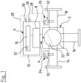
- the hydraulic system is a hydraulic device consisting of two main components, namely a hydraulic unit 2 and a control and drive unit 4.
- the control and drive unit 4 is detachably coupled to the hydraulic unit 2 via a coupling 6 comprising engaging elements on the hydraulic unit 2 and the control and drive unit 4.
- the control and drive unit 4 comprises a drive means 8, for example a drive motor, and a control device 10 controlling the drive means 8.
- a drive means 8 for example a drive motor
- a control device 10 controlling the drive means 8.
- the drive means 8 and the control device 10 are arranged in a common housing 12.
- the hydraulic unit 2 in this example is a mixing valve having a first inlet port 14 and a second inlet port 16 and an outlet port 18.
- the two inlet ports 14, 16 and the outlet port 18 are provided to be connected with further components of the hydraulic system, in particular of a heating system.
- the inlet ports 14, 16 and the outlet port 18 are connected to a valve or actuator space 20 inside which a hydraulic actuator 22 in form of a valve element is arranged.
- the valve element (hydraulic actuator 22) is ball shaped and movable to vary the opening degree of the first inlet port 14 and the second inlet port 16 towards the outlet port 18.
- a mixing ratio of the fluid flow to the outlet port 18 can be varied.
- the hydraulic actuator 22 is connected to the coupling 16 and can be moved by the drive means 8.
- the sensor devices 24 and 26 are temperature sensors detecting the temperature of the fluid flow inside the inlet port 14 and the outlet port 18.
- the first inlet port may for example be connected to a return line of a heating circuit, whereas the outlet port 18 is connected to the supply line of the heating circuit.
- the second inlet port 16 may be connected to a supply line of the heating system delivering a flow of hot water from a heat source like a boiler.
- the sensor devices 24, 26 are connected to the control device 10 via signal lines 28.
- the signal lines 28 are detachable from the control and drive unit 4 by plug connections 30.
- the sensor device 24 and 26 may be connected to the control device 10 via a wireless signal transmission, for example using Bluetooth standard or similar.
- the sensor devices 24 and 26 comprise electronics having a storage means 32 inside the sensor devices 24, 26.
- the control device 10 comprises storage means 32.
- the storage means 32 are provided to store information specifying the hydraulic unit 2. This information may contain an identifier identifying the hydraulic unit 2 and in particular the type of hydraulic unit 2. Alternatively or additionally this information may contain parameters defining characteristics and/or specifications of use of the hydraulic unit 2 which are required for the control device 10 to control the actuator inside the hydraulic unit 2 in a desired manner.
- the information stored in the storage means 32 is required to set up the control, in particular to select a control scheme used by the control device 10 when controlling the hydraulic unit 2 by controlling the drive means 8. For example the control scheme may be specific for a certain size of hydraulic units 2. It may be that the same control and drive unit 4 can be used in connection with different hydraulic units 2, for example of different dimension.
- the hydraulic unit 2 itself is a mechanical unit only, since the drive means 8 and the control device 10 are arranged in a separate control and drive unit 4 which is detachably connected with the hydraulic unit 2.
- the hydraulic unit 2 does not contain any own electronics which may be suitable to store the required information.
- the sensor devices 24 and 26 are auxiliary devices or subdevices inside the hydraulic unit 2 and these subdevices are used to store the required information referring to the entire hydraulic unit 2, i.e. which specify the overall hydraulic unit 2, and not the sensor devices 24, 26 only.
- an electronic component inside a mechanical hydraulic unit is used to store further information going beyond the information referring to the sensor device, namely specifying the mechanical device into which the sensor device is integrated.
- the control device 10 is configured to carry out a verification routine, for example during start of the control device and in particular after being connected to the hydraulic unit 2. During this verification routine it is verified whether all three storage means 32 contain the same information specifying the hydraulic unit 2. If the information stored in all three components is matching or identical, the verification routine for example allows the start of the control on basis of a set up or control scheme relating to the specification of the hydraulic unit 2 stored in the storage means 32. In case that the storage means 32 inside the control device 10 should contain information different to the information contained in the two sensor devices 24 and 26, the setting of the control device 10, i.e.
- the control scheme or program has to be changed.
- the control scheme is set to a control scheme or program matching to the information stored in the two sensor devices.
- the information stored in the storage means 32 of the control device 10 preferably is replaced with identical information stored in the sensor devices 24 and 26 so that finally there is the identical information specifying the hydraulic unit 2 inside all three components.
- This replacement or change of set up may require a confirmation by a user.
- This method allows to connect an unspecified control and drive unit 4 with the hydraulic unit 2 ensuring that the control device 10 inside the control and drive unit 4 is configured or reconfigured to the required setting given by the information stored in the storage means 32 of the two sensor devices 24 and 26. This may simplify the installation of different hydraulic devices or systems for example in a large heating system, since it does not matter whether the control and drive units 4 for several hydraulic units 2 are changed or mixed up. Furthermore, a control and drive unit 4 can easily be replaced in case of a fault.
- this design allows to easily replace one of the sensor devices 24 and 26. If one of the sensor devices 24 and 26 is replaced the control device 10 preferably starts a verification or set up routine again verifying whether the information stored in all three storage means 32 is the same. In this case likely the storage means 32 of the replaced sensor device does not contain matching information. Thus, the control device 10 detects that one sensor device and the storage means 32 of the control device 10 contain identical or matching information and writes identical information into the storage means 32 of the new sensor device so that again all three elements contain the same information specifying the hydraulic unit 2. This may be done in similar manner with more than three components (sensors and control devices). Furthermore, also the sensor devices 24 and 26 may be configured on basis of the information stored in the storage means 32 or received from the control device 10. For example a measurement range may be set according to this information. Alternatively, it may be possible to use sensors which are able to detect different parameters like pressure and temperature and a configuration may define which values are output by the sensor in a specific system.
Landscapes
- Engineering & Computer Science (AREA)
- General Engineering & Computer Science (AREA)
- Mechanical Engineering (AREA)
- Physics & Mathematics (AREA)
- Fluid Mechanics (AREA)
- Chemical & Material Sciences (AREA)
- Analytical Chemistry (AREA)
- General Physics & Mathematics (AREA)
- Automation & Control Theory (AREA)
- Thermal Sciences (AREA)
- Combustion & Propulsion (AREA)
- Fluid-Pressure Circuits (AREA)
Claims (14)
- Hydrauliksystem, das Folgendes umfasst:mindestens eine Hydraulikeinheit (2), die mindestens eine Strömungsbahn, einen Hydraulikstellantrieb (22), der zum Beeinflussen eines Hydraulikstroms durch die Strömungsbahn bereitgestellt wird, und mindestens eine Sensorvorrichtung (24, 26) aufweist, undeine Steuerungsvorrichtung zum Steuern des Hydraulikstellantriebs (22),dadurch gekennzeichnet, dassdie mindestens eine Sensorvorrichtung (24, 26) ein Speichermittel (32) umfasst, das zum Enthalten von Informationen, welche die Hydraulikeinheit (2) spezifizieren, bereitgestellt wird, wobei die Informationen, welche die Hydraulikeinheit (2) spezifizieren, eine Einheitenkennung und/oder mindestens einen Parameter, der die Hydraulikeinheit (2) spezifiziert, umfassen, und dassdie Steuerungsvorrichtung (10) dafür konfiguriert ist, die Informationen, die in dem Speichermittel (32) der Sensorvorrichtung (24, 26) gespeichert sind, zu empfangen und eine Steuerung des Hydraulikstellantriebs (22) auf Grundlage der empfangenen Informationen, welche die Hydraulikeinheit (2) spezifizieren, einzurichten.
- Hydrauliksystem nach Anspruch 1, dadurch gekennzeichnet, dass die Hydraulikeinheit (2) mindestens zwei Sensorvorrichtungen (24, 26) umfasst, die jeweils ein Speichermittel (32) aufweisen, das zum Enthalten von Informationen, welche die Hydraulikeinheit (2) spezifizieren, bereitgestellt wird.
- Hydrauliksystem nach Anspruch 1 oder 2, dadurch gekennzeichnet, dass die Steuerungsvorrichtung Speichermittel (32) aufweist, die zum Enthalten von Informationen, welche die Hydraulikeinheit (2) spezifizieren, bereitgestellt werden.
- Hydrauliksystem nach einem der vorhergehenden Ansprüche, dadurch gekennzeichnet, dass die Hydraulikeinheit (2) mindestens zwei Sensoren (24, 26) umfasst und die Steuerungsvorrichtung (10) dafür konfiguriert ist, eine Steuerung auf Grundlage solcher Informationen, welche die Hydraulikeinheit (2) spezifizieren, einzurichten, die identisch in mindestens zwei von den zwei Sensorvorrichtungen (24, 26) und der Steuerungsvorrichtung (10) gespeichert sind.
- Hydrauliksystem nach Anspruch 4, dadurch gekennzeichnet, dass die Steuerungsvorrichtung (10) dafür konfiguriert ist, die Informationen in der mindestens einen Vorrichtung von den mindestens zwei Sensorvorrichtungen (24, 26) und der Steuerungsvorrichtung (10), welche Vorrichtung nicht identische Informationen umfasst, zu ändern.
- Hydrauliksystem nach Anspruch 5, dadurch gekennzeichnet, dass die Steuerungsvorrichtung dafür konfiguriert ist, die nicht identischen Informationen in der mindestens einen Vorrichtung so zu ändern, dass sie mit den Informationen identisch sind, die in den mindestens zwei anderen Vorrichtungen gespeichert sind, die identische Informationen aufweisen.
- Hydrauliksystem nach einem der vorhergehenden Ansprüche, gekennzeichnet durch ein Antriebsmittel (8), das zum Antreiben des Hydraulikstellantriebs (22) konfiguriert ist, wobei das Antriebsmittel (8) und die Steuerungsvorrichtung (10) vorzugsweise in einer gemeinsamen Antriebs- und Steuerungseinheit (4), ferner vorzugsweise innerhalb eines gemeinsamen Gehäuses (12), angeordnet sind.
- Hydrauliksystem nach einem der vorhergehenden Ansprüche, dadurch gekennzeichnet, dass die Steuerungsvorrichtung (10) oder die Antriebs- und Steuerungseinheit (4) jeweils abnehmbar mit der Hydraulikeinheit (2) verbunden ist.
- Hydrauliksystem nach einem der vorhergehenden Ansprüche, dadurch gekennzeichnet, dass der mindestens eine Sensor (24, 26) zur Signalübertragung über einen lösbaren Kabelanschluss (28) oder durch drahtlose Signalübertragung mit der Steuerungsvorrichtung (10) verbunden ist.
- Hydrauliksystem nach einem der vorhergehenden Ansprüche, dadurch gekennzeichnet, dass der Hydraulikstellantrieb eine Pumpe und/oder ein Ventilelement (22), insbesondere in einem Strömungsvermischungs- oder-teilungsventil, ist.
- Hydrauliksystem nach einem der vorhergehenden Ansprüche, dadurch gekennzeichnet, dass die Hydraulikeinheit (2) mindestens einen Einlassanschluss (14, 16) und einen Auslassanschluss (18) zum Anschluss der Einheit an eine externe Leitung umfasst und einen Stellantriebsraum (20) umfasst, der den Hydraulikstellantrieb (22) enthält, der zwischen dem Einlass- (14) und dem Auslass- (18) -anschluss angeordnet ist.
- Hydrauliksystem nach einem der vorhergehenden Ansprüche, dadurch gekennzeichnet, dass die Hydraulikeinheit (2) eine fluiddichte Kupplung (6) umfasst, die zum Kuppeln des Hydraulikstellantriebs (22) an ein externes Antriebsmittel (8) konfiguriert ist.
- Verfahren zum Steuern eines Hydraulikstellantriebs innerhalb einer Hydraulikeinheit über eine externe Steuerungsvorrichtung (10), dadurch gekennzeichnet, dass mindestens eine Sensorvorrichtung (24, 26) innerhalb der Hydraulikeinheit (2) verwendet wird, um Informationen, welche die Hydraulikeinheit (2) spezifizieren, zu speichern, wobei die Informationen, welche die Hydraulikeinheit (2) spezifizieren, eine Einheitenkennung und/oder mindestens einen Parameter, der die Hydraulikeinheit (2) spezifiziert, umfassen, und dass die Steuerung des Hydraulikstellantriebs (22) durch die Steuerungsvorrichtung (10) auf Grundlage der Informationen eingerichtet wird, die innerhalb der Sensorvorrichtung (24, 26) gespeichert sind.
- Verfahren nach Anspruch 13, dadurch gekennzeichnet, dass die mindestens zwei Sensorvorrichtungen (24, 26) in der Hydraulikeinheit (2) und die Steuerungsvorrichtung (10) jeweils Informationen, die eine Hydraulikeinheit (2) spezifizieren, speichern und dass die Steuerung, die durch die Steuerungsvorrichtung (10) bereitgestellt wird, auf Grundlage solcher Informationen eingerichtet wird, die in mindestens zwei der drei Vorrichtungen identisch sind, die aus den zwei Sensorvorrichtungen (24, 26) und der Steuerungsvorrichtung (10) bestehen.
Priority Applications (3)
| Application Number | Priority Date | Filing Date | Title |
|---|---|---|---|
| EP20209831.5A EP4006660B1 (de) | 2020-11-25 | 2020-11-25 | Hydrauliksystem |
| US17/535,319 US11761465B2 (en) | 2020-11-25 | 2021-11-24 | Hydraulic system |
| CN202111411269.5A CN114607658A (zh) | 2020-11-25 | 2021-11-25 | 液压系统 |
Applications Claiming Priority (1)
| Application Number | Priority Date | Filing Date | Title |
|---|---|---|---|
| EP20209831.5A EP4006660B1 (de) | 2020-11-25 | 2020-11-25 | Hydrauliksystem |
Publications (3)
| Publication Number | Publication Date |
|---|---|
| EP4006660A1 EP4006660A1 (de) | 2022-06-01 |
| EP4006660B1 true EP4006660B1 (de) | 2024-08-07 |
| EP4006660C0 EP4006660C0 (de) | 2024-08-07 |
Family
ID=74175556
Family Applications (1)
| Application Number | Title | Priority Date | Filing Date |
|---|---|---|---|
| EP20209831.5A Active EP4006660B1 (de) | 2020-11-25 | 2020-11-25 | Hydrauliksystem |
Country Status (3)
| Country | Link |
|---|---|
| US (1) | US11761465B2 (de) |
| EP (1) | EP4006660B1 (de) |
| CN (1) | CN114607658A (de) |
Family Cites Families (8)
| Publication number | Priority date | Publication date | Assignee | Title |
|---|---|---|---|---|
| GB0213197D0 (en) * | 2002-06-10 | 2002-07-17 | Cnh Belgium Nv | Vehicle control system and apparatus therefor |
| JP2011185190A (ja) * | 2010-03-10 | 2011-09-22 | Ebara Corp | 制御装置一体型モータポンプ |
| US20180372385A1 (en) * | 2017-06-26 | 2018-12-27 | Trane International Inc. | Compressor cycling control for variable flow systems |
| JP7045209B2 (ja) * | 2018-01-31 | 2022-03-31 | 株式会社荏原製作所 | ポンプ装置の制御ユニット、ポンプ装置、および、ポンプ装置における可変速制御手段のセットアップ異常を判定する方法 |
| EP3527829B1 (de) * | 2018-02-19 | 2022-03-16 | Grundfos Holding A/S | Pumpensystem und pumpensteuerungsverfahren |
| CN108425876A (zh) * | 2018-05-17 | 2018-08-21 | 江苏大学 | 一种适用于泵管路系统的蝶阀装置及其控制方法 |
| CN110242590A (zh) * | 2019-07-19 | 2019-09-17 | 上海上涵自动化科技有限公司 | 一种智能循环泵 |
| CN111306048B (zh) * | 2019-12-09 | 2022-04-05 | 荏原电产(青岛)科技有限公司 | 一种水泵与控制盘信息识别系统及识别方法 |
-
2020
- 2020-11-25 EP EP20209831.5A patent/EP4006660B1/de active Active
-
2021
- 2021-11-24 US US17/535,319 patent/US11761465B2/en active Active
- 2021-11-25 CN CN202111411269.5A patent/CN114607658A/zh active Pending
Also Published As
| Publication number | Publication date |
|---|---|
| US11761465B2 (en) | 2023-09-19 |
| EP4006660C0 (de) | 2024-08-07 |
| US20220163056A1 (en) | 2022-05-26 |
| EP4006660A1 (de) | 2022-06-01 |
| CN114607658A (zh) | 2022-06-10 |
Similar Documents
| Publication | Publication Date | Title |
|---|---|---|
| US7849698B2 (en) | Method and apparatus to sense and establish operation mode for an HVAC control | |
| EP2896899B1 (de) | Ventilsteuerung in einem HLK-System mit Sensoren | |
| CN1910527B (zh) | 分区域供暖、通风与空调系统的正确安装的检验方法 | |
| US8117862B2 (en) | Device and method for recording air conditioning system information | |
| US5237826A (en) | Configuration wiring harness for HVAC controller | |
| RU2663781C2 (ru) | Циркуляционный насосный агрегат для системы нагрева и/или охлаждения | |
| US20250369245A1 (en) | Connected pool and spa heater system | |
| RU2666663C2 (ru) | Гидравлический распределитель для гидравлической системы нагревания и/или охлаждения | |
| CN104633842B (zh) | 供热和/或冷却系统的调节方法和用于该系统的配送装置 | |
| US10655880B1 (en) | System and method for retrofitting HVAC systems | |
| US20080237217A1 (en) | Heater interlock control for air conditioning system | |
| CN105706006B (zh) | 用于诊断供热和/或冷却系统的正确功能的诊断方法 | |
| JP6862920B2 (ja) | 給湯システム | |
| CN101479152A (zh) | 具有自动线路检测的气温控制系统 | |
| EP4006660B1 (de) | Hydrauliksystem | |
| EP1691139B1 (de) | System zum Überprüfen einer Klimaanlage | |
| US8091373B2 (en) | Method of twinning air conditioning units | |
| CN103270375A (zh) | 直通式加热器 | |
| EP4006661A1 (de) | Hydrauliksystem | |
| US20020059841A1 (en) | Method for testing a heating system | |
| JP3867771B2 (ja) | 給湯装置 | |
| AU2018201282B2 (en) | Water heating system | |
| US20240361007A1 (en) | Hot water supply system | |
| EP3982057B1 (de) | Warmwasserheizvorrichtung | |
| JP2002073426A (ja) | フラッシュメモリの書換え制御方法 |
Legal Events
| Date | Code | Title | Description |
|---|---|---|---|
| PUAI | Public reference made under article 153(3) epc to a published international application that has entered the european phase |
Free format text: ORIGINAL CODE: 0009012 |
|
| STAA | Information on the status of an ep patent application or granted ep patent |
Free format text: STATUS: THE APPLICATION HAS BEEN PUBLISHED |
|
| AK | Designated contracting states |
Kind code of ref document: A1 Designated state(s): AL AT BE BG CH CY CZ DE DK EE ES FI FR GB GR HR HU IE IS IT LI LT LU LV MC MK MT NL NO PL PT RO RS SE SI SK SM TR |
|
| STAA | Information on the status of an ep patent application or granted ep patent |
Free format text: STATUS: REQUEST FOR EXAMINATION WAS MADE |
|
| 17P | Request for examination filed |
Effective date: 20221201 |
|
| RBV | Designated contracting states (corrected) |
Designated state(s): AL AT BE BG CH CY CZ DE DK EE ES FI FR GB GR HR HU IE IS IT LI LT LU LV MC MK MT NL NO PL PT RO RS SE SI SK SM TR |
|
| REG | Reference to a national code |
Ref country code: DE Ref legal event code: R079 Ipc: G05B0019040000 Ref country code: DE Ref legal event code: R079 Ref document number: 602020035227 Country of ref document: DE Free format text: PREVIOUS MAIN CLASS: G05B0019042000 Ipc: G05B0019040000 |
|
| GRAP | Despatch of communication of intention to grant a patent |
Free format text: ORIGINAL CODE: EPIDOSNIGR1 |
|
| STAA | Information on the status of an ep patent application or granted ep patent |
Free format text: STATUS: GRANT OF PATENT IS INTENDED |
|
| RIC1 | Information provided on ipc code assigned before grant |
Ipc: G05B 19/04 20060101AFI20240220BHEP |
|
| INTG | Intention to grant announced |
Effective date: 20240305 |
|
| GRAS | Grant fee paid |
Free format text: ORIGINAL CODE: EPIDOSNIGR3 |
|
| GRAA | (expected) grant |
Free format text: ORIGINAL CODE: 0009210 |
|
| STAA | Information on the status of an ep patent application or granted ep patent |
Free format text: STATUS: THE PATENT HAS BEEN GRANTED |
|
| AK | Designated contracting states |
Kind code of ref document: B1 Designated state(s): AL AT BE BG CH CY CZ DE DK EE ES FI FR GB GR HR HU IE IS IT LI LT LU LV MC MK MT NL NO PL PT RO RS SE SI SK SM TR |
|
| REG | Reference to a national code |
Ref country code: GB Ref legal event code: FG4D |
|
| REG | Reference to a national code |
Ref country code: CH Ref legal event code: EP |
|
| REG | Reference to a national code |
Ref country code: IE Ref legal event code: FG4D |
|
| REG | Reference to a national code |
Ref country code: DE Ref legal event code: R096 Ref document number: 602020035227 Country of ref document: DE |
|
| U01 | Request for unitary effect filed |
Effective date: 20240906 |
|
| U07 | Unitary effect registered |
Designated state(s): AT BE BG DE DK EE FI FR IT LT LU LV MT NL PT RO SE SI Effective date: 20240920 |
|
| U1O | Appointed representative for the unitary patent procedure deleted after the registration of the unitary effect | ||
| U20 | Renewal fee for the european patent with unitary effect paid |
Year of fee payment: 5 Effective date: 20241126 |
|
| PG25 | Lapsed in a contracting state [announced via postgrant information from national office to epo] |
Ref country code: NO Free format text: LAPSE BECAUSE OF FAILURE TO SUBMIT A TRANSLATION OF THE DESCRIPTION OR TO PAY THE FEE WITHIN THE PRESCRIBED TIME-LIMIT Effective date: 20241107 |
|
| PG25 | Lapsed in a contracting state [announced via postgrant information from national office to epo] |
Ref country code: GR Free format text: LAPSE BECAUSE OF FAILURE TO SUBMIT A TRANSLATION OF THE DESCRIPTION OR TO PAY THE FEE WITHIN THE PRESCRIBED TIME-LIMIT Effective date: 20241108 Ref country code: PL Free format text: LAPSE BECAUSE OF FAILURE TO SUBMIT A TRANSLATION OF THE DESCRIPTION OR TO PAY THE FEE WITHIN THE PRESCRIBED TIME-LIMIT Effective date: 20240807 |
|
| PGFP | Annual fee paid to national office [announced via postgrant information from national office to epo] |
Ref country code: GB Payment date: 20241120 Year of fee payment: 5 |
|
| PG25 | Lapsed in a contracting state [announced via postgrant information from national office to epo] |
Ref country code: IS Free format text: LAPSE BECAUSE OF FAILURE TO SUBMIT A TRANSLATION OF THE DESCRIPTION OR TO PAY THE FEE WITHIN THE PRESCRIBED TIME-LIMIT Effective date: 20241207 |
|
| PG25 | Lapsed in a contracting state [announced via postgrant information from national office to epo] |
Ref country code: HR Free format text: LAPSE BECAUSE OF FAILURE TO SUBMIT A TRANSLATION OF THE DESCRIPTION OR TO PAY THE FEE WITHIN THE PRESCRIBED TIME-LIMIT Effective date: 20240807 |
|
| PG25 | Lapsed in a contracting state [announced via postgrant information from national office to epo] |
Ref country code: ES Free format text: LAPSE BECAUSE OF FAILURE TO SUBMIT A TRANSLATION OF THE DESCRIPTION OR TO PAY THE FEE WITHIN THE PRESCRIBED TIME-LIMIT Effective date: 20240807 Ref country code: RS Free format text: LAPSE BECAUSE OF FAILURE TO SUBMIT A TRANSLATION OF THE DESCRIPTION OR TO PAY THE FEE WITHIN THE PRESCRIBED TIME-LIMIT Effective date: 20241107 |
|
| PG25 | Lapsed in a contracting state [announced via postgrant information from national office to epo] |
Ref country code: RS Free format text: LAPSE BECAUSE OF FAILURE TO SUBMIT A TRANSLATION OF THE DESCRIPTION OR TO PAY THE FEE WITHIN THE PRESCRIBED TIME-LIMIT Effective date: 20241107 Ref country code: PL Free format text: LAPSE BECAUSE OF FAILURE TO SUBMIT A TRANSLATION OF THE DESCRIPTION OR TO PAY THE FEE WITHIN THE PRESCRIBED TIME-LIMIT Effective date: 20240807 Ref country code: NO Free format text: LAPSE BECAUSE OF FAILURE TO SUBMIT A TRANSLATION OF THE DESCRIPTION OR TO PAY THE FEE WITHIN THE PRESCRIBED TIME-LIMIT Effective date: 20241107 Ref country code: IS Free format text: LAPSE BECAUSE OF FAILURE TO SUBMIT A TRANSLATION OF THE DESCRIPTION OR TO PAY THE FEE WITHIN THE PRESCRIBED TIME-LIMIT Effective date: 20241207 Ref country code: HR Free format text: LAPSE BECAUSE OF FAILURE TO SUBMIT A TRANSLATION OF THE DESCRIPTION OR TO PAY THE FEE WITHIN THE PRESCRIBED TIME-LIMIT Effective date: 20240807 Ref country code: GR Free format text: LAPSE BECAUSE OF FAILURE TO SUBMIT A TRANSLATION OF THE DESCRIPTION OR TO PAY THE FEE WITHIN THE PRESCRIBED TIME-LIMIT Effective date: 20241108 Ref country code: ES Free format text: LAPSE BECAUSE OF FAILURE TO SUBMIT A TRANSLATION OF THE DESCRIPTION OR TO PAY THE FEE WITHIN THE PRESCRIBED TIME-LIMIT Effective date: 20240807 |
|
| PG25 | Lapsed in a contracting state [announced via postgrant information from national office to epo] |
Ref country code: SM Free format text: LAPSE BECAUSE OF FAILURE TO SUBMIT A TRANSLATION OF THE DESCRIPTION OR TO PAY THE FEE WITHIN THE PRESCRIBED TIME-LIMIT Effective date: 20240807 |
|
| PG25 | Lapsed in a contracting state [announced via postgrant information from national office to epo] |
Ref country code: CZ Free format text: LAPSE BECAUSE OF FAILURE TO SUBMIT A TRANSLATION OF THE DESCRIPTION OR TO PAY THE FEE WITHIN THE PRESCRIBED TIME-LIMIT Effective date: 20240807 |
|
| PG25 | Lapsed in a contracting state [announced via postgrant information from national office to epo] |
Ref country code: SK Free format text: LAPSE BECAUSE OF FAILURE TO SUBMIT A TRANSLATION OF THE DESCRIPTION OR TO PAY THE FEE WITHIN THE PRESCRIBED TIME-LIMIT Effective date: 20240807 |
|
| PLBE | No opposition filed within time limit |
Free format text: ORIGINAL CODE: 0009261 |
|
| STAA | Information on the status of an ep patent application or granted ep patent |
Free format text: STATUS: NO OPPOSITION FILED WITHIN TIME LIMIT |
|
| REG | Reference to a national code |
Ref country code: CH Ref legal event code: PL |
|
| PG25 | Lapsed in a contracting state [announced via postgrant information from national office to epo] |
Ref country code: MC Free format text: LAPSE BECAUSE OF FAILURE TO SUBMIT A TRANSLATION OF THE DESCRIPTION OR TO PAY THE FEE WITHIN THE PRESCRIBED TIME-LIMIT Effective date: 20240807 |
|
| REG | Reference to a national code |
Ref country code: CH Ref legal event code: PL |
|
| 26N | No opposition filed |
Effective date: 20250508 |
|
| PG25 | Lapsed in a contracting state [announced via postgrant information from national office to epo] |
Ref country code: CH Free format text: LAPSE BECAUSE OF NON-PAYMENT OF DUE FEES Effective date: 20241130 |
|
| PG25 | Lapsed in a contracting state [announced via postgrant information from national office to epo] |
Ref country code: IE Free format text: LAPSE BECAUSE OF NON-PAYMENT OF DUE FEES Effective date: 20241125 |