EP4006483B1 - Spektral-konfokales messgerät und messverfahren - Google Patents
Spektral-konfokales messgerät und messverfahren Download PDFInfo
- Publication number
- EP4006483B1 EP4006483B1 EP20940002.7A EP20940002A EP4006483B1 EP 4006483 B1 EP4006483 B1 EP 4006483B1 EP 20940002 A EP20940002 A EP 20940002A EP 4006483 B1 EP4006483 B1 EP 4006483B1
- Authority
- EP
- European Patent Office
- Prior art keywords
- light
- measurement
- light source
- lens group
- objective lens
- Prior art date
- Legal status (The legal status is an assumption and is not a legal conclusion. Google has not performed a legal analysis and makes no representation as to the accuracy of the status listed.)
- Active
Links
Images


Classifications
-
- G—PHYSICS
- G01—MEASURING; TESTING
- G01N—INVESTIGATING OR ANALYSING MATERIALS BY DETERMINING THEIR CHEMICAL OR PHYSICAL PROPERTIES
- G01N21/00—Investigating or analysing materials by the use of optical means, i.e. using sub-millimetre waves, infrared, visible or ultraviolet light
- G01N21/17—Systems in which incident light is modified in accordance with the properties of the material investigated
- G01N21/25—Colour; Spectral properties, i.e. comparison of effect of material on the light at two or more different wavelengths or wavelength bands
- G01N21/31—Investigating relative effect of material at wavelengths characteristic of specific elements or molecules, e.g. atomic absorption spectrometry
-
- G—PHYSICS
- G01—MEASURING; TESTING
- G01J—MEASUREMENT OF INTENSITY, VELOCITY, SPECTRAL CONTENT, POLARISATION, PHASE OR PULSE CHARACTERISTICS OF INFRARED, VISIBLE OR ULTRAVIOLET LIGHT; COLORIMETRY; RADIATION PYROMETRY
- G01J3/00—Spectrometry; Spectrophotometry; Monochromators; Measuring colours
- G01J3/02—Details
- G01J3/0205—Optical elements not provided otherwise, e.g. optical manifolds, diffusers, windows
-
- G—PHYSICS
- G01—MEASURING; TESTING
- G01B—MEASURING LENGTH, THICKNESS OR SIMILAR LINEAR DIMENSIONS; MEASURING ANGLES; MEASURING AREAS; MEASURING IRREGULARITIES OF SURFACES OR CONTOURS
- G01B11/00—Measuring arrangements characterised by the use of optical techniques
- G01B11/02—Measuring arrangements characterised by the use of optical techniques for measuring length, width or thickness
- G01B11/06—Measuring arrangements characterised by the use of optical techniques for measuring length, width or thickness for measuring thickness ; e.g. of sheet material
- G01B11/0608—Height gauges
-
- G—PHYSICS
- G01—MEASURING; TESTING
- G01B—MEASURING LENGTH, THICKNESS OR SIMILAR LINEAR DIMENSIONS; MEASURING ANGLES; MEASURING AREAS; MEASURING IRREGULARITIES OF SURFACES OR CONTOURS
- G01B9/00—Measuring instruments characterised by the use of optical techniques
- G01B9/04—Measuring microscopes
-
- G—PHYSICS
- G01—MEASURING; TESTING
- G01J—MEASUREMENT OF INTENSITY, VELOCITY, SPECTRAL CONTENT, POLARISATION, PHASE OR PULSE CHARACTERISTICS OF INFRARED, VISIBLE OR ULTRAVIOLET LIGHT; COLORIMETRY; RADIATION PYROMETRY
- G01J3/00—Spectrometry; Spectrophotometry; Monochromators; Measuring colours
- G01J3/02—Details
- G01J3/10—Arrangements of light sources specially adapted for spectrometry or colorimetry
-
- G—PHYSICS
- G01—MEASURING; TESTING
- G01J—MEASUREMENT OF INTENSITY, VELOCITY, SPECTRAL CONTENT, POLARISATION, PHASE OR PULSE CHARACTERISTICS OF INFRARED, VISIBLE OR ULTRAVIOLET LIGHT; COLORIMETRY; RADIATION PYROMETRY
- G01J3/00—Spectrometry; Spectrophotometry; Monochromators; Measuring colours
- G01J3/12—Generating the spectrum; Monochromators
- G01J3/18—Generating the spectrum; Monochromators using diffraction elements, e.g. grating
-
- G—PHYSICS
- G01—MEASURING; TESTING
- G01J—MEASUREMENT OF INTENSITY, VELOCITY, SPECTRAL CONTENT, POLARISATION, PHASE OR PULSE CHARACTERISTICS OF INFRARED, VISIBLE OR ULTRAVIOLET LIGHT; COLORIMETRY; RADIATION PYROMETRY
- G01J3/00—Spectrometry; Spectrophotometry; Monochromators; Measuring colours
- G01J3/28—Investigating the spectrum
-
- G—PHYSICS
- G02—OPTICS
- G02B—OPTICAL ELEMENTS, SYSTEMS OR APPARATUS
- G02B21/00—Microscopes
- G02B21/0004—Microscopes specially adapted for specific applications
- G02B21/002—Scanning microscopes
- G02B21/0024—Confocal scanning microscopes (CSOMs) or confocal "macroscopes"; Accessories which are not restricted to use with CSOMs, e.g. sample holders
- G02B21/0028—Confocal scanning microscopes (CSOMs) or confocal "macroscopes"; Accessories which are not restricted to use with CSOMs, e.g. sample holders specially adapted for specific applications, e.g. for endoscopes, ophthalmoscopes, attachments to conventional microscopes
-
- G—PHYSICS
- G02—OPTICS
- G02B—OPTICAL ELEMENTS, SYSTEMS OR APPARATUS
- G02B21/00—Microscopes
- G02B21/0004—Microscopes specially adapted for specific applications
- G02B21/002—Scanning microscopes
- G02B21/0024—Confocal scanning microscopes (CSOMs) or confocal "macroscopes"; Accessories which are not restricted to use with CSOMs, e.g. sample holders
- G02B21/0032—Optical details of illumination, e.g. light-sources, pinholes, beam splitters, slits, fibers
-
- G—PHYSICS
- G02—OPTICS
- G02B—OPTICAL ELEMENTS, SYSTEMS OR APPARATUS
- G02B21/00—Microscopes
- G02B21/0004—Microscopes specially adapted for specific applications
- G02B21/002—Scanning microscopes
- G02B21/0024—Confocal scanning microscopes (CSOMs) or confocal "macroscopes"; Accessories which are not restricted to use with CSOMs, e.g. sample holders
- G02B21/0052—Optical details of the image generation
- G02B21/0064—Optical details of the image generation multi-spectral or wavelength-selective arrangements, e.g. wavelength fan-out, chromatic profiling
-
- G—PHYSICS
- G02—OPTICS
- G02B—OPTICAL ELEMENTS, SYSTEMS OR APPARATUS
- G02B21/00—Microscopes
- G02B21/0004—Microscopes specially adapted for specific applications
- G02B21/002—Scanning microscopes
- G02B21/0024—Confocal scanning microscopes (CSOMs) or confocal "macroscopes"; Accessories which are not restricted to use with CSOMs, e.g. sample holders
- G02B21/008—Details of detection or image processing, including general computer control
-
- G—PHYSICS
- G02—OPTICS
- G02B—OPTICAL ELEMENTS, SYSTEMS OR APPARATUS
- G02B27/00—Optical systems or apparatus not provided for by any of the groups G02B1/00 - G02B26/00, G02B30/00
- G02B27/10—Beam splitting or combining systems
- G02B27/108—Beam splitting or combining systems for sampling a portion of a beam or combining a small beam in a larger one, e.g. wherein the area ratio or power ratio of the divided beams significantly differs from unity, without spectral selectivity
-
- G—PHYSICS
- G01—MEASURING; TESTING
- G01B—MEASURING LENGTH, THICKNESS OR SIMILAR LINEAR DIMENSIONS; MEASURING ANGLES; MEASURING AREAS; MEASURING IRREGULARITIES OF SURFACES OR CONTOURS
- G01B2210/00—Aspects not specifically covered by any group under G01B, e.g. of wheel alignment, caliper-like sensors
- G01B2210/50—Using chromatic effects to achieve wavelength-dependent depth resolution
-
- G—PHYSICS
- G01—MEASURING; TESTING
- G01N—INVESTIGATING OR ANALYSING MATERIALS BY DETERMINING THEIR CHEMICAL OR PHYSICAL PROPERTIES
- G01N2201/00—Features of devices classified in G01N21/00
- G01N2201/06—Illumination; Optics
- G01N2201/063—Illuminating optical parts
- G01N2201/0633—Directed, collimated illumination
-
- G—PHYSICS
- G01—MEASURING; TESTING
- G01N—INVESTIGATING OR ANALYSING MATERIALS BY DETERMINING THEIR CHEMICAL OR PHYSICAL PROPERTIES
- G01N2201/00—Features of devices classified in G01N21/00
- G01N2201/06—Illumination; Optics
- G01N2201/063—Illuminating optical parts
- G01N2201/0635—Structured illumination, e.g. with grating
Definitions
- the invention relates to the technical field of optical displacement measurement, in particular to a spectral confocal measurement device and a measurement method thereof.
- Spectral confocal sensor is a non-contact displacement sensor based on wavelength displacement modulation, which has become a hot research topic and been widely used in the fields of film thickness measurement, precision positioning, and precision instrument manufacturing, because its measurement accuracy reaches sub-micron or even nanometer level, and it is not sensitive to object tilt and surface texture, etc., it also has strong stray light resistance ability.
- the spectral confocal measurement system uses a light source to irradiate the surface of the object to be measured, and reflected spectral information is detected by a CCD industrial camera or spectrometer, etc., to determine the peak wavelength focused on the surface of the object, thereby obtaining axial distance information of the surface of the object to be measured.
- the principle is to use a dispersive objective lens group to focus and disperse the light from the light source, and form a continuous monochromatic light focus on the optical axis with different distances to the dispersive objective lens group, thereby establishing a linear relationship between wavelength and axial distance, and then use the spectral information reflected by the surface of the object to be measured to obtain the corresponding position information.
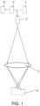
- FIG. 1 shows an existing spectral confocal measurement device.
- the light is emitted from the light source 1', enters the coupling portion 2' to be transmitted to the sampling portion 3', and then is projected to the measured object 4' which reflects a reflected light carrying measurement information to return back to the coupling portion 2'along the original light path. Subsequently, partial or all of the reflected light passes through the beam splitter 5', and is finally converted into an electrical signal by the sensor 6', thereby analyzing and obtaining location measurement results.
- One objective of the present invention is to provide a spectral confocal measurement device, thereby improving measurement accuracy and reducing production cost.
- Another objective of the present invention is to provide a spectral confocal measurement method, thereby improving measurement accuracy and reducing production cost.
- the present invention provides a spectral confocal measurement device according to claim 1.
- the light source portion further includes a focusing lens located below the light source.
- the optical sampling portion further includes a reflecting mirror located between the dispersive objective lens group and the light-incident hole, the reflecting mirror is arranged on an axis of the dispersive objective lens group, and configured to receive the reflected light output from the dispersive objective lens group and guide the reflected light to the light-outgoing hole.
- a reflecting mirror located between the dispersive objective lens group and the light-incident hole, the reflecting mirror is arranged on an axis of the dispersive objective lens group, and configured to receive the reflected light output from the dispersive objective lens group and guide the reflected light to the light-outgoing hole.
- the light source portion further includes a reflecting mirror located between the focusing lens and the light-incident hole, the reflecting mirror is arranged on an axis of the dispersive objective lens group, and configured to receive the reflected light output from the dispersive objective lens group and guide the reflected light to the light-outgoing hole, and the light-outgoing hole and the light-incident hole are the same hole.
- a reflecting mirror located between the focusing lens and the light-incident hole, the reflecting mirror is arranged on an axis of the dispersive objective lens group, and configured to receive the reflected light output from the dispersive objective lens group and guide the reflected light to the light-outgoing hole, and the light-outgoing hole and the light-incident hole are the same hole.
- the dispersive objective lens group includes a first-stage dispersive objective lens group located below the light source and a second-stage dispersive objective lens group located below the first-stage dispersive objective lens group.
- a diaphragm is provided between the first-stage dispersive objective lens group and the second-stage dispersive objective lens group.
- the measurement portion includes:
- the spectrometer includes:
- the present invention provides a spectral confocal measurement method according to claim 9.
- a specific optical path is configured in the spectral confocal measurement device and method of the present invention, specifically, the incident measurement beam is emitted along a first predetermined path and reflected along a second predetermined path that is different from the opposite direction of the first predetermined path.
- undesired beams are filtered, so that the purity of the spectrum of the emitted light can be improved, and the measurement accuracy of the subsequent measurement portion is improved accordingly.
- the essence of the present invention is to provide an improved spectral confocal measurement device and measurement method thereof, which optimizes the light path by controlling the direction of incident light, thereby improving measurement accuracy and reducing production costs.
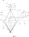
- a spectral confocal measurement device 200 includes a light source portion 210, an optical sampling portion 220 and a measurement portion 230.
- the light source portion 210 is configured to emit a broad-spectrum light beam with a certain wavelength range in a first predetermined path
- the optical sampling portion 220 is configured to converge the broad-spectrum light beam emitted from the light source portion 210 on different measurement surfaces of an object to be measured, and output a reflected light in a second predetermined path that is different from a reverse direction of the first predetermined path
- the measurement portion 230 is configured to receive and process the reflected light from the optical sampling portion 220 to obtain a measurement result.
- the light source portion 210 is encapsulated by a housing 210a and includes a light source 211, a light source controller 212 connected to the light source 211, and a focusing lens 213 located below the light source 211.
- the light source 211 may be a point light source or a line light source, such as an LED light source, a laser, or other light sources such as mercury vapors.
- the light source 211 is configured to emit continuous visible light beams having different wavelengths from the blue wavelength range to the red wavelength range as the measurement light.
- the light source controller 220 is configured to control the direction and path of the incident light of the light source, thereby optimizing the direction and the path of the outgoing light.
- the direction and the path of the outgoing light of the present invention are different, which will be described in detail below in conjunction with different embodiments. Since the light beam needs to be focused before entering the optical sampling portion 220, the focusing lens 213 is arranged on the optical sampling portion 220.
- the light source portion 210 and the optical sampling portion 220 are connected, by an optical fiber, for example, and a light-incident hole (that is, a port) is provided therebetween, and the light-incident hole is provided at the focal point of the focusing lens 213.
- the optical sampling portion 220 is encapsulated by a housing 220a, and includes a light-incident hole 221, a dispersive objective lens group 222, a light-outgoing hole 223 and a reflecting mirror 224.
- the light-incident hole 221 and the light-outgoing hole 223 are arranged on the housing 220a, the dispersive objective lens group 222 is arranged in the housing 220a, and the reflecting mirror 224 is located between the dispersive objective lens group 222 and the light-incident hole 221, and located at the axis of the dispersive objective lens group 222. Further, the light-outgoing hole 224 is located on the other side of the housing 220a to connect with the measurement portion 230.
- the light-outgoing hole 224 can be a pinhole or an aperture.
- the shape of the housing 220a of the optical sampling portion 220 can be set according to actual requirements, which is not limited.
- a measurement beam emitted from the light source portion 210 is emitted to inside of the housing of the optical sampling portion 220 by passing through the focusing lens 213 and the light-incident hole 221, and then passes through the dispersive objective lens group 222 and is emitted to a measurement surface S from an irradiation surface 220b provided at the front end of the housing.
- the dispersive objective lens group 222 is at least one lens involved in the spectral confocal sensor and configured to generate axial chromatic aberration. Specifically, the dispersive objective lens group 222 is configured to focus the light incident on the optical sampling portion 220 at a focal position of the optical axis corresponding to the wavelength.
- the light beams of different wavelengths contained in the corresponding light source are focused to different focus positions.
- the light source includes continuous visible light beams with a certain wavelength range, for example, light beams of red, green and blue are separated from each other and emitted from the irradiation surface of the housing to the measurement surface. It should be noted that, light with other colors and other wavelengths may also be emitted.
- the measurement beam is reflected by the measurement surface, passes through the dispersive objective lens group 222 to enter the reflecting mirror 224, and then is guided to the light-outgoing hole 223, to reach the measurement portion 230 finally.
- the measurement portion 230 includes a spectrometer 240, a sensor 250, and a processor (not shown).
- the spectrometer 240 is configured to receive and process the reflected light from the optical sampling portion 220
- the sensor 250 is configured to convert the reflected light from the spectrometer 240 into an electrical signal
- the processor is configured to calculate a measurement result according to the electrical signal of the sensor 250.
- the spectrometer 240 includes a collimator lens 241, a diffraction grating 242, and a focusing lens 243.
- the collimator lens 241 is configured to make the measurement beam emitted from the light-outgoing hole irradiate to the diffraction grating 242 in a substantially collimated manner
- the diffraction grating 242 is configured to diffract the substantially collimated measurement beam
- the focusing lens 243 is configured to image the diffracted light diffracted by the diffraction grating 242 on the sensor 250.
- +1-order diffracted light is imaged on the sensor 250, but other diffracted light such as of -1-order diffracted light may also be imaged.
- the specific structure and configuration of the diffraction grating 242 is not limited.
- the focusing lens 243 is a lens with small chromatic aberration, and can image diffracted light on the sensor 250 regardless of the wavelength of the measurement light.
- the specific structure of the sensor 250 is not limited. For example, a CMOS line sensor or a CCD line sensor can be used.
- the sensor 250 is configured to convert the measurement light into an electrical signal and transmit the electrical signal to the processor. Based on the received signal, the processor can calculate the position of the object to be measured.
- the specific calculation method may refer to the prior art, which will not be described in detail here.
- a measurement beam is emitted from the point light source 211 to enter the focusing lens 213 in the form of a whole light beam (that is, the beam that does not shield any area), and then is focused on the light-incident hole 221 to enter the housing 220a of the optical sampling portion 220, and then enters the dispersive objective lens group 222 in a predetermined direction in a form of an annular light beam (that is, the beam that shields the central area), as shown by the arrow A1 in the figure.
- the measurement beam is emitted in the form of annular light beam, with the beam at the center being shielded, and then passes through the dispersive objective lens group 222 to reach the measurement surface S, and then the reflected light from the measurement surface S passes through the central part of the dispersive objective lens group 222 along the path of C1, finally, the beam is reflected from the reflecting mirror 224 to the light-outgoing hole 223.
- the light outgoing path of the measurement beam does not return from the original light incident path, but takes the above-mentioned specific path. In such an arrangement, inconsistent and undesirable beams are filtered, so that the purity of the spectrum of the emitted light can be improved, thereby improving the measurement accuracy of the subsequent measurement portion.
- the number of dispersive objective lenses in the dispersive objective lens group 222 in the optical sampling portion 220 of the present invention is not limited, and can be set to one or more to meet different design requirements.
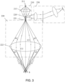
- FIG. 3 shows an example using a point light source.
- the differences from the first embodiment include: the light outgoing manner of the point light source 211 before entering the optical sampling portion 220, the arrangement of the light-incident hole, and the arrangement of the reflecting mirror 224' for guiding the light to the measurement portion 230.
- the measurement beam of the linear light source 211' passes through the light-incident slit 221' and only enters the single side of the first-stage dispersive objective lens group 222a and then enter the single side of the second stage dispersive objective lens group 222b along the first predetermined path A3, and reaches the measurement surface S.
- the measurement beam is reflected from the measurement surface S and emitted from the opposite symmetrical side of the second-stage dispersive objective lens group 222b along the second predetermined path C3, and then is reflected to the light-incident slit 221' of the line light source, and then enters the measurement portion (not shown) located on one side of the light-incident slit 221' for measurement.
- the measurement portion in this light path control manner, only the beam with a specific wavelength on the confocal line can enter the dispersive lens group through the measurement surface and finally enter the measurement portion (imaging system) through the light-incident slit 221', and the undesirable beam cannot enter the measurement portion.
- the interference of other reflection wavelengths outside the confocal line is effectively reduced, so that the test sensitivity is higher and the measurement accuracy is improved.
- the measurement portion in this embodiment has the same structure as that in the first embodiment, which will not be repeated here.
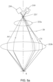
- FIG. 5a-5c show the structure and light path control of another preferred embodiment of the spectral confocal measurement device of the present invention.
- the confocal measurement device uses a linear light source.
- the light source 210 and the measurement portion 230 are located on the same side of the light-incident slit 221', the first-stage dispersive objective lens group 222a and the second-stage dispersive objective lens group 222b are arranged coaxially.
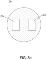
- a diaphragm 26 is provided between the first-stage dispersive objective lens group 222a and the second-stage dispersive objective lens group 222b. As shown in FIG.
- the diaphragm 26 is provided with two channels 26a and 26b, respectively, for allowing the beams to input or output.
- the shape of the two channels is square, but other shapes are also available.
- the specific light path control follows. Under the control of the light source controller, the measurement beam of the light source 210 passes through the light-incident slit 221', enters from the single side of the first-stage dispersive objective lens group 222a along the first predetermined path A4, then passes through the light-incident port 26a of the diaphragm 26 to enter the single side of the second-stage dispersive objective lens group 222b, and then reaches the measurement surface S. The measurement beam is then reflected from the measurement surface S and emitted along the second predetermined path C4 from the opposite symmetrical side of the second-stage dispersive objective lens group 222b.
- the reflected beam is emitted from the second-stage dispersive objective lens group 222b, then passes through the light-outgoing port 26b of the diaphragm 26 to pass through the light entrance slit 221', and finally enters the measurement portion 230 located on the side of the light-incident slit 221' to make the measurements.
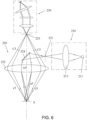
- FIG. 6 An example shown in FIG. 6 is obtained by interchanging the positions of the light source portion and the measurement portion shown in FIG. 2 . That is, the light source 211 in the light source portion 210 emits the measurement beam towards the housing of the optical sampling portion 220 through the focusing lens 213 and the light-incident hole 221, and the measurement beam is reflected by the reflected mirror 224, and then passes through the central part of the dispersive objective lens group 222, and reaches the measurement surface S, as shown the local light incident path indicated by sections A5+a5.
- the present invention further discloses a spectral confocal measurement method according to claim 9.
- a specific optical path is configured in the spectral confocal measurement device and method of the present invention, specifically, the incident measurement beam is emitted along a first predetermined path and reflected along a second predetermined path that is different from the opposite direction of the first predetermined path.
- undesired beams are filtered, thereby effectively reducing the interference of other reflected wavelengths beyond the confocal line, so that the purity of the spectrum of the emitted light can be improved, and the test sensitivity and measurement accuracy of the subsequent measurement portion are improved accordingly.
- the device has a simple structure to reduce production costs.
Landscapes
- Physics & Mathematics (AREA)
- Spectroscopy & Molecular Physics (AREA)
- General Physics & Mathematics (AREA)
- Analytical Chemistry (AREA)
- Chemical & Material Sciences (AREA)
- Optics & Photonics (AREA)
- Health & Medical Sciences (AREA)
- General Health & Medical Sciences (AREA)
- Biochemistry (AREA)
- Life Sciences & Earth Sciences (AREA)
- Immunology (AREA)
- Pathology (AREA)
- Surgery (AREA)
- Radiology & Medical Imaging (AREA)
- Engineering & Computer Science (AREA)
- Computer Vision & Pattern Recognition (AREA)
- General Engineering & Computer Science (AREA)
- Ophthalmology & Optometry (AREA)
- Length Measuring Devices By Optical Means (AREA)
- Microscoopes, Condenser (AREA)
Claims (9)
- Spektrale konfokale Messeinrichtung (200), umfassend:einen Lichtquellenabschnitt (210), ausgebildet zum Aussenden eines breitbandigen Lichtstrahls mit einem bestimmten Wellenlängenbereich in einem ersten vorgegebenen Pfad;einen optischen Abtastabschnitt (220), ausgebildet zum Konvergieren des vom Lichtquellenabschnitt (210) ausgesendeten breitbandigen Lichtstrahls auf unterschiedlichen Messoberflächen eines zu messenden Objekts und zum Ausgeben eines reflektierten Lichts in einem zweiten vorgegebenen Pfad, der sich von einer Rückwärtsrichtung des ersten vorgegebenen Pfads unterscheidet; undeinen Messabschnitt (230), ausgebildet zum Empfangen und Verarbeiten des reflektierten Lichts vom optischen Abtastabschnitt zur Gewinnung eines Messergebnisses;wobei der Lichtquellenabschnitt (210) eine Lichtquelle (211') und einen mit der Lichtquelle (211') verbundenen Lichtquellensteuerer (212) umfasst und der optische Abtastabschnitt (220) ein Lichteintrittsloch (221'), eine dispersive Objektivlinsengruppe (222) und ein Lichtaustrittsloch (221') umfasst;die Lichtquelle (211') eine Linienlichtquelle ist, unter Steuerung des Lichtquellensteuerers (212) wird der breitbandige Lichtstrahl der Linienlichtquelle durch das Lichteintrittsloch (221') ausgesendet, tritt dann in eine erste Seite der dispersiven Objektivlinsengruppe (222) ein und gelangt über den ersten vorgegebenen Pfad zur Messoberfläche; und der zweite vorgegebene Pfad folgt: das von der Messoberfläche reflektierte Licht wird von einer zweiten Seite der dispersiven Objektivlinsengruppe (222), die der ersten Seite entgegengesetzt ist, ausgegeben und tritt durch das Lichtaustrittsloch (221') in den Messabschnitt ein, wobei das Lichtaustrittsloch (221') und das Lichteintrittsloch (221') dasselbe Loch sind.
- Die spektrale konfokale Messeinrichtung gemäß Anspruch 1, wobei der Lichtquellenabschnitt (210) ferner eine Fokussierlinse (213) umfasst, die sich unterhalb der Lichtquelle (211') befindet.
- Die spektrale konfokale Messeinrichtung gemäß Anspruch 1, wobei die dispersive Objektivlinsengruppe (222) eine erste Stufe der dispersiven Objektivlinsengruppe (222a), die sich unterhalb der Lichtquelle (211') befindet, und eine zweite Stufe der dispersiven Objektivlinsengruppe (222b), die sich unterhalb der ersten Stufe der dispersiven Objektivlinsengruppe (222a) befindet, umfasst.
- Die spektrale konfokale Messeinrichtung gemäß Anspruch 3, wobei eine Blende (26) zwischen der ersten Stufe der dispersiven Objektivlinsengruppe (222a) und der zweiten Stufe der dispersiven Objektivlinsengruppe (222b) vorgesehen ist.
- Die spektrale konfokale Messeinrichtung gemäß Anspruch 4, wobei die Blende (26) mit zwei Kanälen (26a, 26b) versehen ist, die jeweils zur Ein- oder Ausgabe des breitbandigen Lichtstrahls dienen.
- Die spektrale konfokale Messeinrichtung gemäß Anspruch 5, wobei die Form der zwei Kanäle (26a, 26b) quadratisch ist.
- Die spektrale konfokale Messeinrichtung gemäß Anspruch 1, wobei der Messabschnitt (230) umfasst:ein Spektrometer (240), ausgebildet zum Empfangen und Verarbeiten des reflektierten Lichts vom optischen Abtastabschnitt (220);einen Sensor (250), ausgebildet zum Umwandeln des reflektierten Lichts vom Spektrometer in ein elektrisches Signal; undeinen Prozessor, ausgebildet zum Berechnen eines Messergebnisses anhand des elektrischen Signals des Sensors (250).
- Die spektrale konfokale Messeinrichtung gemäß Anspruch 7, wobei das Spektrometer (240) umfasst:eine Kollimatorlinse (241), ausgebildet zum Bestrahlen des von dem Lichtaustrittsloch (221) ausgesendeten Messstrahls auf das Beugungsgitter;ein Beugungsgitter (242), ausgebildet zum Beugen des im Wesentlichen kollimierten Messstrahls; undeine Fokussierlinse (243), ausgebildet zum Konvergieren des vom Beugungsgitter gebeugten reflektierten Lichts zum Sensor (250).
- Spektrales konfokales Messverfahren, umfassend:Steuern einer Lichtquelle (211') zum Aussenden eines breitbandigen Lichtstrahls mit einem bestimmten Wellenlängenbereich in einem ersten vorgegebenen Pfad, wobei die Lichtquelle (211') eine Linienlichtquelle ist;Konvergieren des von der Lichtquelle (211') ausgesendeten breitbandigen Lichtstrahls auf unterschiedlichen Messoberflächen des zu messenden Objekts und Ausgeben von reflektiertem Licht in einem zweiten vorgegebenen Pfad, der sich vom ersten vorgegebenen Pfad unterscheidet, wobei der breitbandige Lichtstrahl durch das Lichteintrittsloch (221') ausgesendet wird, dann in eine erste Seite der dispersiven Objektivlinsengruppe (222) vom Lichteintrittsloch (221') eintritt und über den ersten vorgegebenen Pfad die Messoberfläche erreicht, und das von der Messoberfläche reflektierte Licht von einer zweiten Seite der dispersiven Objektivlinsengruppe (222), die der ersten Seite entgegengesetzt ist, ausgegeben wird und durch das Lichtaustrittsloch (221') in den Messabschnitt eintritt, wobei das Lichtaustrittsloch (221') und das Lichteintrittsloch (221') dasselbe Loch sind; undEmpfangen und Verarbeiten des reflektierten Lichts und Berechnen eines Messergebnisses.
Applications Claiming Priority (1)
| Application Number | Priority Date | Filing Date | Title |
|---|---|---|---|
| PCT/CN2020/095524 WO2021248398A1 (zh) | 2020-06-11 | 2020-06-11 | 光谱共焦测量装置及测量方法 |
Publications (4)
| Publication Number | Publication Date |
|---|---|
| EP4006483A1 EP4006483A1 (de) | 2022-06-01 |
| EP4006483A4 EP4006483A4 (de) | 2023-04-12 |
| EP4006483C0 EP4006483C0 (de) | 2025-05-21 |
| EP4006483B1 true EP4006483B1 (de) | 2025-05-21 |
Family
ID=78846743
Family Applications (1)
| Application Number | Title | Priority Date | Filing Date |
|---|---|---|---|
| EP20940002.7A Active EP4006483B1 (de) | 2020-06-11 | 2020-06-11 | Spektral-konfokales messgerät und messverfahren |
Country Status (5)
| Country | Link |
|---|---|
| US (1) | US12085501B2 (de) |
| EP (1) | EP4006483B1 (de) |
| JP (1) | JP7410969B2 (de) |
| KR (1) | KR102747251B1 (de) |
| WO (1) | WO2021248398A1 (de) |
Families Citing this family (9)
| Publication number | Priority date | Publication date | Assignee | Title |
|---|---|---|---|---|
| CN213481255U (zh) * | 2020-11-16 | 2021-06-18 | 海伯森技术(深圳)有限公司 | 一种线光谱共焦传感器 |
| DE102022202778B4 (de) | 2022-02-11 | 2024-05-16 | Micro-Epsilon Optronic Gmbh | System und Verfahren zur konfokal-chromatischen Linienabstandsmessung |
| JP2025517268A (ja) * | 2022-02-11 | 2025-06-05 | マイクロ‐エプシロン オプトロニク ゲーエムベーハー | 共焦点クロマティック光線距離測定システムおよび方法 |
| CN115077391A (zh) * | 2022-03-25 | 2022-09-20 | 上海洛丁森工业自动化设备有限公司 | 微位移传感器及位移测量方法 |
| CN116518870B (zh) * | 2023-04-20 | 2024-04-19 | 华中科技大学 | 一种双光栅大量程高分辨光谱线共焦成像装置 |
| CN116295833A (zh) * | 2023-04-25 | 2023-06-23 | 武汉加特林光学仪器有限公司 | 一种光谱测量装置及精确定位方法 |
| CN116447988B (zh) * | 2023-06-16 | 2023-10-31 | 宁德微图智能科技有限公司 | 一种采用宽光谱光源的三角激光测量方法 |
| CN118999376B (zh) * | 2024-10-18 | 2025-01-21 | 北京特思迪半导体设备有限公司 | 基于光谱共聚焦的膜厚测量方法及设备 |
| CN119197339B (zh) * | 2024-11-26 | 2025-03-28 | 浙江大学 | 基于光谱共焦原理的在位无线测量装置及方法 |
Family Cites Families (33)
| Publication number | Priority date | Publication date | Assignee | Title |
|---|---|---|---|---|
| US5785651A (en) * | 1995-06-07 | 1998-07-28 | Keravision, Inc. | Distance measuring confocal microscope |
| US6573998B2 (en) | 1997-11-06 | 2003-06-03 | Cynovad, Inc. | Optoelectronic system using spatiochromatic triangulation |
| FR2805342B1 (fr) | 2000-02-21 | 2002-07-12 | Sabban Joseph Cohen | Capteur de numerisation 3d optique haute resolution a faible angle de triangulation |
| DE10242374A1 (de) | 2002-09-12 | 2004-04-01 | Siemens Ag | Konfokaler Abstandssensor |
| DE10321896A1 (de) | 2003-05-07 | 2004-12-09 | Universität Stuttgart | Optischer Sensor und Verfahren mittels Triangulation, insbesondere zur chromatischen Objekt-Tiefenabtastung |
| US7768629B2 (en) | 2006-05-12 | 2010-08-03 | Voith Patent Gmbh | Device and process for optical distance measurement |
| US20080250255A1 (en) | 2007-04-06 | 2008-10-09 | Broadcom Corporation | System and method for applying power over ethernet to portable computing devices |
| EP2304400A1 (de) * | 2008-06-25 | 2011-04-06 | Bioptigen, Inc. | Volumenphasengitterspektrometer sowie entsprechende verfahren und systeme |
| CN101706405B (zh) | 2009-11-10 | 2011-05-04 | 上海理工大学 | 获取透过率起伏空间相关频谱的装置及其方法 |
| JP5477183B2 (ja) | 2010-06-14 | 2014-04-23 | オムロン株式会社 | 計測装置 |
| JP2012093197A (ja) | 2010-10-26 | 2012-05-17 | Canon Inc | 高さの計測装置 |
| JP2012189547A (ja) | 2011-03-14 | 2012-10-04 | Omron Corp | 変位センサ |
| DE102011083726A1 (de) | 2011-09-29 | 2013-04-04 | Siemens Aktiengesellschaft | Konfokales Spektrometer und Verfahren zur Bildgebung in einem konfokalen Spektrometer |
| DE102012022304A1 (de) | 2012-02-29 | 2013-08-29 | Confovis Gmbh | Anordnung zur optischen Abtastung und Profilometrie nach dem Lichtschnittverfahren |
| JP5966982B2 (ja) | 2013-03-15 | 2016-08-10 | オムロン株式会社 | 共焦点計測装置 |
| CN104061901B (zh) | 2013-03-19 | 2016-08-31 | 力诚仪器有限公司 | 立体距离测定方法及其系统 |
| CN104034268B (zh) | 2014-07-01 | 2016-08-24 | 西安工业大学 | 双缝干涉条纹解码光谱共焦位移传感器及其位移测量方法 |
| US9829312B2 (en) * | 2015-07-09 | 2017-11-28 | Mituloyo Corporation | Chromatic confocal range sensor comprising a camera portion |
| CN105241850A (zh) | 2015-07-17 | 2016-01-13 | 北京理工大学 | 双轴激光共焦libs、拉曼光谱-质谱成像方法与装置 |
| CN106405803B (zh) | 2016-11-22 | 2019-02-01 | 南京先进激光技术研究院 | 一种大轴向色差的线性色散物镜 |
| CN106443996A (zh) | 2016-12-07 | 2017-02-22 | 深圳立仪科技有限公司 | 光谱共聚焦镜片组件 |
| CN110095079A (zh) | 2018-01-29 | 2019-08-06 | 陈亮嘉 | 共焦形貌测量系统及共焦形貌侦测方法 |
| EP3811025B1 (de) * | 2018-06-20 | 2023-11-01 | Precitec Optronik GmbH | Vorrichtung zur chromatisch konfokalen optischen vermessung und konfokalen abbildung eines messobjekts sowie verfahren |
| CN108981579B (zh) * | 2018-07-25 | 2020-08-18 | 浙江大学 | 一种用于大范围测量的光谱共焦测量系统及方法 |
| JP7205781B2 (ja) | 2018-09-18 | 2023-01-17 | オムロン株式会社 | 光学計測装置 |
| CN109580640A (zh) * | 2018-12-07 | 2019-04-05 | 哈尔滨工业大学 | 一种环形光式暗场共焦亚表面无损检测装置和方法 |
| CN109945800B (zh) | 2019-03-28 | 2020-06-05 | 浙江大学 | 一种用于三维面型测量的线形光谱共焦系统 |
| CN210036602U (zh) | 2019-07-29 | 2020-02-07 | 海伯森技术(深圳)有限公司 | 一种光谱共焦位移传感探头 |
| CN110412758A (zh) | 2019-08-13 | 2019-11-05 | 茂莱(南京)仪器有限公司 | 一种基于光谱共焦的成像检测装置 |
| CN110887450B (zh) | 2019-12-23 | 2024-09-17 | 海伯森技术(深圳)有限公司 | 一种基于光谱共焦的物体表面三维信息测量系统及方法 |
| CN110849271A (zh) | 2019-12-23 | 2020-02-28 | 海伯森技术(深圳)有限公司 | 一种光谱共焦测量系统及方法 |
| CN111426287A (zh) | 2020-04-23 | 2020-07-17 | 华侨大学 | 一种并行彩色共聚焦平面度测量系统 |
| CN111486952A (zh) | 2020-06-02 | 2020-08-04 | 南京引创光电科技有限公司 | 一种光学测量系统 |
-
2020
- 2020-06-11 KR KR1020217042219A patent/KR102747251B1/ko active Active
- 2020-06-11 US US17/753,395 patent/US12085501B2/en active Active
- 2020-06-11 WO PCT/CN2020/095524 patent/WO2021248398A1/zh not_active Ceased
- 2020-06-11 JP JP2021557727A patent/JP7410969B2/ja active Active
- 2020-06-11 EP EP20940002.7A patent/EP4006483B1/de active Active
Also Published As
| Publication number | Publication date |
|---|---|
| KR102747251B1 (ko) | 2024-12-31 |
| EP4006483A4 (de) | 2023-04-12 |
| KR20220123177A (ko) | 2022-09-06 |
| JP2022541364A (ja) | 2022-09-26 |
| EP4006483C0 (de) | 2025-05-21 |
| US12085501B2 (en) | 2024-09-10 |
| WO2021248398A1 (zh) | 2021-12-16 |
| JP7410969B2 (ja) | 2024-01-10 |
| US20230087237A1 (en) | 2023-03-23 |
| EP4006483A1 (de) | 2022-06-01 |
Similar Documents
| Publication | Publication Date | Title |
|---|---|---|
| EP4006483B1 (de) | Spektral-konfokales messgerät und messverfahren | |
| CN111879239B (zh) | 光谱共焦测量装置及测量方法 | |
| TWI245114B (en) | Apparatus for measuring imaging spectrograph | |
| CN113137931B (zh) | 一种光谱共焦可测量面型或厚度的装置及方法 | |
| CN111413070A (zh) | 亮度检测装置及其检测方法 | |
| US10837832B2 (en) | Spectrometer and method for measuring the spectral characteristics thereof | |
| CN215984415U (zh) | 一种线式扫描光谱共聚测量系统 | |
| WO2023185199A1 (zh) | 光谱共焦测量装置 | |
| WO2017119812A1 (en) | High resolution broadband monolithic spectrometer and method | |
| US6618154B2 (en) | Optical measurement arrangement, in particular for layer thickness measurement | |
| US5592285A (en) | Optical source position and direction sensor | |
| CN118962956A (zh) | 自动聚焦装置及离焦距离的确定方法 | |
| CN115248078B (zh) | 一种基于线光谱的可调节光源装置及其使用方法 | |
| JP2021051074A (ja) | 分光分析装置 | |
| CN114812396B (zh) | 一种光谱共焦测量系统 | |
| CN119948310A (zh) | 包括摄像机的彩色共焦测量设备 | |
| JP2025517268A (ja) | 共焦点クロマティック光線距離測定システムおよび方法 | |
| CN210833435U (zh) | 一种基于三角测量法的彩色三角位移传感器 | |
| CN113916151A (zh) | 一种光谱黑洞共焦测量面型或厚度的装置及方法 | |
| CN220322561U (zh) | 颜色传感器 | |
| JP3494148B2 (ja) | フォーカス検出装置及びレーザ検査加工装置 | |
| CN118032126B (zh) | 立体光谱仪 | |
| CN120085445B (zh) | 一种低畸变消色差镜头及宽谱域分段式光谱探测装置 | |
| CN117629405B (zh) | 光谱仪 | |
| JPS63218828A (ja) | 測色装置 |
Legal Events
| Date | Code | Title | Description |
|---|---|---|---|
| STAA | Information on the status of an ep patent application or granted ep patent |
Free format text: STATUS: THE INTERNATIONAL PUBLICATION HAS BEEN MADE |
|
| PUAI | Public reference made under article 153(3) epc to a published international application that has entered the european phase |
Free format text: ORIGINAL CODE: 0009012 |
|
| STAA | Information on the status of an ep patent application or granted ep patent |
Free format text: STATUS: REQUEST FOR EXAMINATION WAS MADE |
|
| 17P | Request for examination filed |
Effective date: 20220228 |
|
| AK | Designated contracting states |
Kind code of ref document: A1 Designated state(s): AL AT BE BG CH CY CZ DE DK EE ES FI FR GB GR HR HU IE IS IT LI LT LU LV MC MK MT NL NO PL PT RO RS SE SI SK SM TR |
|
| A4 | Supplementary search report drawn up and despatched |
Effective date: 20230313 |
|
| RIC1 | Information provided on ipc code assigned before grant |
Ipc: G02B 27/10 20060101ALI20230306BHEP Ipc: G02B 21/00 20060101ALI20230306BHEP Ipc: G01B 11/06 20060101ALI20230306BHEP Ipc: G01B 9/04 20060101ALI20230306BHEP Ipc: G01B 11/02 20060101AFI20230306BHEP |
|
| TPAC | Observations filed by third parties |
Free format text: ORIGINAL CODE: EPIDOSNTIPA |
|
| DAV | Request for validation of the european patent (deleted) | ||
| DAX | Request for extension of the european patent (deleted) | ||
| GRAP | Despatch of communication of intention to grant a patent |
Free format text: ORIGINAL CODE: EPIDOSNIGR1 |
|
| STAA | Information on the status of an ep patent application or granted ep patent |
Free format text: STATUS: GRANT OF PATENT IS INTENDED |
|
| INTG | Intention to grant announced |
Effective date: 20250213 |
|
| GRAS | Grant fee paid |
Free format text: ORIGINAL CODE: EPIDOSNIGR3 |
|
| GRAA | (expected) grant |
Free format text: ORIGINAL CODE: 0009210 |
|
| STAA | Information on the status of an ep patent application or granted ep patent |
Free format text: STATUS: THE PATENT HAS BEEN GRANTED |
|
| AK | Designated contracting states |
Kind code of ref document: B1 Designated state(s): AL AT BE BG CH CY CZ DE DK EE ES FI FR GB GR HR HU IE IS IT LI LT LU LV MC MK MT NL NO PL PT RO RS SE SI SK SM TR |
|
| REG | Reference to a national code |
Ref country code: GB Ref legal event code: FG4D |
|
| REG | Reference to a national code |
Ref country code: CH Ref legal event code: EP |
|
| REG | Reference to a national code |
Ref country code: DE Ref legal event code: R096 Ref document number: 602020051893 Country of ref document: DE |
|
| REG | Reference to a national code |
Ref country code: IE Ref legal event code: FG4D |
|
| U01 | Request for unitary effect filed |
Effective date: 20250612 |
|
| U07 | Unitary effect registered |
Designated state(s): AT BE BG DE DK EE FI FR IT LT LU LV MT NL PT RO SE SI Effective date: 20250625 |
|
| U20 | Renewal fee for the european patent with unitary effect paid |
Year of fee payment: 6 Effective date: 20250622 |
|
| PG25 | Lapsed in a contracting state [announced via postgrant information from national office to epo] |
Ref country code: ES Free format text: LAPSE BECAUSE OF FAILURE TO SUBMIT A TRANSLATION OF THE DESCRIPTION OR TO PAY THE FEE WITHIN THE PRESCRIBED TIME-LIMIT Effective date: 20250521 |
|
| PG25 | Lapsed in a contracting state [announced via postgrant information from national office to epo] |
Ref country code: NO Free format text: LAPSE BECAUSE OF FAILURE TO SUBMIT A TRANSLATION OF THE DESCRIPTION OR TO PAY THE FEE WITHIN THE PRESCRIBED TIME-LIMIT Effective date: 20250821 Ref country code: GR Free format text: LAPSE BECAUSE OF FAILURE TO SUBMIT A TRANSLATION OF THE DESCRIPTION OR TO PAY THE FEE WITHIN THE PRESCRIBED TIME-LIMIT Effective date: 20250822 |
|
| PG25 | Lapsed in a contracting state [announced via postgrant information from national office to epo] |
Ref country code: PL Free format text: LAPSE BECAUSE OF FAILURE TO SUBMIT A TRANSLATION OF THE DESCRIPTION OR TO PAY THE FEE WITHIN THE PRESCRIBED TIME-LIMIT Effective date: 20250521 |
|
| PG25 | Lapsed in a contracting state [announced via postgrant information from national office to epo] |
Ref country code: HR Free format text: LAPSE BECAUSE OF FAILURE TO SUBMIT A TRANSLATION OF THE DESCRIPTION OR TO PAY THE FEE WITHIN THE PRESCRIBED TIME-LIMIT Effective date: 20250521 |
|
| PG25 | Lapsed in a contracting state [announced via postgrant information from national office to epo] |
Ref country code: RS Free format text: LAPSE BECAUSE OF FAILURE TO SUBMIT A TRANSLATION OF THE DESCRIPTION OR TO PAY THE FEE WITHIN THE PRESCRIBED TIME-LIMIT Effective date: 20250821 |
|
| PG25 | Lapsed in a contracting state [announced via postgrant information from national office to epo] |
Ref country code: IS Free format text: LAPSE BECAUSE OF FAILURE TO SUBMIT A TRANSLATION OF THE DESCRIPTION OR TO PAY THE FEE WITHIN THE PRESCRIBED TIME-LIMIT Effective date: 20250921 |