EP4006408A1 - Fahrzeugleuchte, fahrzeugbeleuchtungsvorrichtung, fahrzeugleuchte und fahrzeug - Google Patents
Fahrzeugleuchte, fahrzeugbeleuchtungsvorrichtung, fahrzeugleuchte und fahrzeug Download PDFInfo
- Publication number
- EP4006408A1 EP4006408A1 EP20924803.8A EP20924803A EP4006408A1 EP 4006408 A1 EP4006408 A1 EP 4006408A1 EP 20924803 A EP20924803 A EP 20924803A EP 4006408 A1 EP4006408 A1 EP 4006408A1
- Authority
- EP
- European Patent Office
- Prior art keywords
- low
- light
- optical element
- vehicle
- primary optical
- Prior art date
- Legal status (The legal status is an assumption and is not a legal conclusion. Google has not performed a legal analysis and makes no representation as to the accuracy of the status listed.)
- Granted
Links
- 230000003287 optical effect Effects 0.000 title claims abstract description 157
- 230000005494 condensation Effects 0.000 claims description 85
- 238000009833 condensation Methods 0.000 claims description 85
- 239000007787 solid Substances 0.000 claims description 4
- 230000008901 benefit Effects 0.000 abstract description 5
- 238000005286 illumination Methods 0.000 abstract 2
- 238000010586 diagram Methods 0.000 description 8
- 238000009434 installation Methods 0.000 description 7
- 230000000694 effects Effects 0.000 description 3
- 239000011159 matrix material Substances 0.000 description 2
- 238000004891 communication Methods 0.000 description 1
- 229910052736 halogen Inorganic materials 0.000 description 1
- 150000002367 halogens Chemical class 0.000 description 1
- 230000003993 interaction Effects 0.000 description 1
- 239000000463 material Substances 0.000 description 1
- 229910052724 xenon Inorganic materials 0.000 description 1
- FHNFHKCVQCLJFQ-UHFFFAOYSA-N xenon atom Chemical compound [Xe] FHNFHKCVQCLJFQ-UHFFFAOYSA-N 0.000 description 1
Images


Classifications
-
- F—MECHANICAL ENGINEERING; LIGHTING; HEATING; WEAPONS; BLASTING
- F21—LIGHTING
- F21S—NON-PORTABLE LIGHTING DEVICES; SYSTEMS THEREOF; VEHICLE LIGHTING DEVICES SPECIALLY ADAPTED FOR VEHICLE EXTERIORS
- F21S41/00—Illuminating devices specially adapted for vehicle exteriors, e.g. headlamps
- F21S41/10—Illuminating devices specially adapted for vehicle exteriors, e.g. headlamps characterised by the light source
- F21S41/14—Illuminating devices specially adapted for vehicle exteriors, e.g. headlamps characterised by the light source characterised by the type of light source
- F21S41/141—Light emitting diodes [LED]
- F21S41/143—Light emitting diodes [LED] the main emission direction of the LED being parallel to the optical axis of the illuminating device
-
- F—MECHANICAL ENGINEERING; LIGHTING; HEATING; WEAPONS; BLASTING
- F21—LIGHTING
- F21S—NON-PORTABLE LIGHTING DEVICES; SYSTEMS THEREOF; VEHICLE LIGHTING DEVICES SPECIALLY ADAPTED FOR VEHICLE EXTERIORS
- F21S41/00—Illuminating devices specially adapted for vehicle exteriors, e.g. headlamps
- F21S41/10—Illuminating devices specially adapted for vehicle exteriors, e.g. headlamps characterised by the light source
- F21S41/14—Illuminating devices specially adapted for vehicle exteriors, e.g. headlamps characterised by the light source characterised by the type of light source
- F21S41/141—Light emitting diodes [LED]
- F21S41/151—Light emitting diodes [LED] arranged in one or more lines
-
- B—PERFORMING OPERATIONS; TRANSPORTING
- B60—VEHICLES IN GENERAL
- B60Q—ARRANGEMENT OF SIGNALLING OR LIGHTING DEVICES, THE MOUNTING OR SUPPORTING THEREOF OR CIRCUITS THEREFOR, FOR VEHICLES IN GENERAL
- B60Q1/00—Arrangement of optical signalling or lighting devices, the mounting or supporting thereof or circuits therefor
- B60Q1/02—Arrangement of optical signalling or lighting devices, the mounting or supporting thereof or circuits therefor the devices being primarily intended to illuminate the way ahead or to illuminate other areas of way or environments
- B60Q1/04—Arrangement of optical signalling or lighting devices, the mounting or supporting thereof or circuits therefor the devices being primarily intended to illuminate the way ahead or to illuminate other areas of way or environments the devices being headlights
- B60Q1/14—Arrangement of optical signalling or lighting devices, the mounting or supporting thereof or circuits therefor the devices being primarily intended to illuminate the way ahead or to illuminate other areas of way or environments the devices being headlights having dimming means
-
- F—MECHANICAL ENGINEERING; LIGHTING; HEATING; WEAPONS; BLASTING
- F21—LIGHTING
- F21S—NON-PORTABLE LIGHTING DEVICES; SYSTEMS THEREOF; VEHICLE LIGHTING DEVICES SPECIALLY ADAPTED FOR VEHICLE EXTERIORS
- F21S41/00—Illuminating devices specially adapted for vehicle exteriors, e.g. headlamps
- F21S41/10—Illuminating devices specially adapted for vehicle exteriors, e.g. headlamps characterised by the light source
- F21S41/14—Illuminating devices specially adapted for vehicle exteriors, e.g. headlamps characterised by the light source characterised by the type of light source
- F21S41/141—Light emitting diodes [LED]
- F21S41/147—Light emitting diodes [LED] the main emission direction of the LED being angled to the optical axis of the illuminating device
-
- F—MECHANICAL ENGINEERING; LIGHTING; HEATING; WEAPONS; BLASTING
- F21—LIGHTING
- F21S—NON-PORTABLE LIGHTING DEVICES; SYSTEMS THEREOF; VEHICLE LIGHTING DEVICES SPECIALLY ADAPTED FOR VEHICLE EXTERIORS
- F21S41/00—Illuminating devices specially adapted for vehicle exteriors, e.g. headlamps
- F21S41/20—Illuminating devices specially adapted for vehicle exteriors, e.g. headlamps characterised by refractors, transparent cover plates, light guides or filters
- F21S41/24—Light guides
-
- F—MECHANICAL ENGINEERING; LIGHTING; HEATING; WEAPONS; BLASTING
- F21—LIGHTING
- F21S—NON-PORTABLE LIGHTING DEVICES; SYSTEMS THEREOF; VEHICLE LIGHTING DEVICES SPECIALLY ADAPTED FOR VEHICLE EXTERIORS
- F21S41/00—Illuminating devices specially adapted for vehicle exteriors, e.g. headlamps
- F21S41/20—Illuminating devices specially adapted for vehicle exteriors, e.g. headlamps characterised by refractors, transparent cover plates, light guides or filters
- F21S41/25—Projection lenses
- F21S41/255—Lenses with a front view of circular or truncated circular outline
-
- F—MECHANICAL ENGINEERING; LIGHTING; HEATING; WEAPONS; BLASTING
- F21—LIGHTING
- F21S—NON-PORTABLE LIGHTING DEVICES; SYSTEMS THEREOF; VEHICLE LIGHTING DEVICES SPECIALLY ADAPTED FOR VEHICLE EXTERIORS
- F21S41/00—Illuminating devices specially adapted for vehicle exteriors, e.g. headlamps
- F21S41/20—Illuminating devices specially adapted for vehicle exteriors, e.g. headlamps characterised by refractors, transparent cover plates, light guides or filters
- F21S41/25—Projection lenses
- F21S41/265—Composite lenses; Lenses with a patch-like shape
-
- F—MECHANICAL ENGINEERING; LIGHTING; HEATING; WEAPONS; BLASTING
- F21—LIGHTING
- F21S—NON-PORTABLE LIGHTING DEVICES; SYSTEMS THEREOF; VEHICLE LIGHTING DEVICES SPECIALLY ADAPTED FOR VEHICLE EXTERIORS
- F21S41/00—Illuminating devices specially adapted for vehicle exteriors, e.g. headlamps
- F21S41/20—Illuminating devices specially adapted for vehicle exteriors, e.g. headlamps characterised by refractors, transparent cover plates, light guides or filters
- F21S41/25—Projection lenses
- F21S41/27—Thick lenses
-
- F—MECHANICAL ENGINEERING; LIGHTING; HEATING; WEAPONS; BLASTING
- F21—LIGHTING
- F21S—NON-PORTABLE LIGHTING DEVICES; SYSTEMS THEREOF; VEHICLE LIGHTING DEVICES SPECIALLY ADAPTED FOR VEHICLE EXTERIORS
- F21S41/00—Illuminating devices specially adapted for vehicle exteriors, e.g. headlamps
- F21S41/20—Illuminating devices specially adapted for vehicle exteriors, e.g. headlamps characterised by refractors, transparent cover plates, light guides or filters
- F21S41/25—Projection lenses
- F21S41/275—Lens surfaces, e.g. coatings or surface structures
-
- F—MECHANICAL ENGINEERING; LIGHTING; HEATING; WEAPONS; BLASTING
- F21—LIGHTING
- F21S—NON-PORTABLE LIGHTING DEVICES; SYSTEMS THEREOF; VEHICLE LIGHTING DEVICES SPECIALLY ADAPTED FOR VEHICLE EXTERIORS
- F21S41/00—Illuminating devices specially adapted for vehicle exteriors, e.g. headlamps
- F21S41/20—Illuminating devices specially adapted for vehicle exteriors, e.g. headlamps characterised by refractors, transparent cover plates, light guides or filters
- F21S41/285—Refractors, transparent cover plates, light guides or filters not provided in groups F21S41/24 - F21S41/2805
-
- F—MECHANICAL ENGINEERING; LIGHTING; HEATING; WEAPONS; BLASTING
- F21—LIGHTING
- F21S—NON-PORTABLE LIGHTING DEVICES; SYSTEMS THEREOF; VEHICLE LIGHTING DEVICES SPECIALLY ADAPTED FOR VEHICLE EXTERIORS
- F21S41/00—Illuminating devices specially adapted for vehicle exteriors, e.g. headlamps
- F21S41/40—Illuminating devices specially adapted for vehicle exteriors, e.g. headlamps characterised by screens, non-reflecting members, light-shielding members or fixed shades
- F21S41/43—Illuminating devices specially adapted for vehicle exteriors, e.g. headlamps characterised by screens, non-reflecting members, light-shielding members or fixed shades characterised by the shape thereof
-
- F—MECHANICAL ENGINEERING; LIGHTING; HEATING; WEAPONS; BLASTING
- F21—LIGHTING
- F21W—INDEXING SCHEME ASSOCIATED WITH SUBCLASSES F21K, F21L, F21S and F21V, RELATING TO USES OR APPLICATIONS OF LIGHTING DEVICES OR SYSTEMS
- F21W2102/00—Exterior vehicle lighting devices for illuminating purposes
- F21W2102/10—Arrangement or contour of the emitted light
- F21W2102/13—Arrangement or contour of the emitted light for high-beam region or low-beam region
- F21W2102/135—Arrangement or contour of the emitted light for high-beam region or low-beam region the light having cut-off lines, i.e. clear borderlines between emitted regions and dark regions
- F21W2102/155—Arrangement or contour of the emitted light for high-beam region or low-beam region the light having cut-off lines, i.e. clear borderlines between emitted regions and dark regions having inclined and horizontal cutoff lines
-
- F—MECHANICAL ENGINEERING; LIGHTING; HEATING; WEAPONS; BLASTING
- F21—LIGHTING
- F21W—INDEXING SCHEME ASSOCIATED WITH SUBCLASSES F21K, F21L, F21S and F21V, RELATING TO USES OR APPLICATIONS OF LIGHTING DEVICES OR SYSTEMS
- F21W2107/00—Use or application of lighting devices on or in particular types of vehicles
- F21W2107/10—Use or application of lighting devices on or in particular types of vehicles for land vehicles
-
- F—MECHANICAL ENGINEERING; LIGHTING; HEATING; WEAPONS; BLASTING
- F21—LIGHTING
- F21Y—INDEXING SCHEME ASSOCIATED WITH SUBCLASSES F21K, F21L, F21S and F21V, RELATING TO THE FORM OR THE KIND OF THE LIGHT SOURCES OR OF THE COLOUR OF THE LIGHT EMITTED
- F21Y2115/00—Light-generating elements of semiconductor light sources
- F21Y2115/10—Light-emitting diodes [LED]
Definitions
- the present disclosure relates to vehicle lights, and specifically relates to a vehicle light optical element assembly.
- the present disclosure further relates to a vehicle lighting device, a vehicle light and a vehicle.
- a projection lighting system of an LED light source commonly used in vehicle lights generally includes a light source, a reflection element, a light shield plate and an optical lens.
- Light emitted by the light source is emitted to the light shield plate after being reflected by the reflection element. After being intercepted by the light shield plate, the light is projected by the optical lens to form a lighting light shape with a light and shade cut-off line.
- the dimension of the reflection element needs to have a larger coverage range relative to a light-exiting angle of the light source to ensure certain system light efficiency, but this is in prominent contradiction with the trend of increasingly compact modelings of vehicles in the future. Therefore, a compact, lightweight and efficient optical system is needed to meet the strong market demand.
- the problem to be solved by the first aspect of the present disclosure is to provide a vehicle light optical element assembly which is compact in structure, smaller in size and high in assembling accuracy.
- a vehicle light optical element assembly in the vehicle lighting device is compact in structure, smaller in size and high in assembling accuracy.
- a vehicle light optical element assembly in the vehicle light is compact in structure, smaller in size and high in assembling accuracy.
- a vehicle light optical element assembly of the vehicle is compact in structure, smaller in size and high in assembling accuracy.
- the first aspect of the present disclosure provides a vehicle light optical element assembly, including a low-beam primary optical element, a high-beam primary optical element provided below the low-beam primary optical element, and a lens provided at the front end of the low-beam primary optical element and/or the high-beam primary optical element.
- the low-beam primary optical element and/or the high-beam primary optical element are/is integrated with the lens;
- the high-beam primary optical element includes at least one high-beam condensation part; a high-beam light-exiting surface is formed at the front end of the high-beam condensation part; or, the high-beam primary optical element sequentially, from back to front, includes at least one high-beam condensation part and a high-beam light passing part; the high-beam light passing part and the lens light-incidence part are integrated; a front edge of the upper surface of the high-beam light passing part is formed into a high-beam cut-off line
- the low-beam sequentially, from back to front includes at least one low-beam condensation part and a low-beam light passing part
- the high-beam sequentially, from back to front includes at least one high-beam condensation part and a high-beam light passing part
- the low-beam light passing part and the high-beam light passing part are integrated with the lens light-incidence part
- a front edge of the lower surface of the low-beam light passing part is formed into a low-beam cut-off line structure
- a front edge of the upper surface of the high-beam light passing part is formed into a high-beam cut-off line structure.
- a wedge-shaped gap is formed between the low-beam light passing part and the high-beam light passing part;
- the lens includes the lens light-incidence part and a lens light-exiting part;
- the lens light-incidence part is a plane, a backwards protruding curved surface or a forwards protruding curved surface;
- the lens light-exiting part is a forwards protruding curved surface;
- the low-beam primary optical element and the high-beam primary optical element are suitable for focusing and collimating light and then forming a low-beam lighting light shape and a high-beam lighting light shape via the lens.
- a plurality of low-beam condensation parts are provided in a left-right direction, and a plurality of high-beam condensation parts are provided in a left-right direction.
- the low-beam condensation part is of a condensation cup structure or a protrusion structure which protrudes towards the back. More preferably, the high-beam condensation part is of a condensation cup structure or a protrusion structure which protrudes towards the back.
- the back end of the condensation cup structure is provided with a concave cavity; the bottom of the concave cavity is provided with a protrusion; an external contour surface of the condensation cup structure is of a curved structure having an aperture that is gradually increased from the back end to the front end; or the condensation cup structure is solid, a light-incidence surface of which is a plane, a convex curved surface or a concave curved surface; and the external contour surface of the condensation cup structure is of a curved structure having an aperture that is gradually increased from the back end to the front end.
- the second aspect of the present disclosure provides a vehicle lighting device, including low-beam light sources, high-beam light sources, and the vehicle light optical element assembly according to any one of the above-mentioned technical solutions.
- the low-beam light sources are in one-to-one correspondence to the low-beam condensation parts
- the high-beam light sources are in one-to-one correspondence to the high-beam condensation parts.
- the vehicle lighting device further includes a low-beam circuit board and a high-beam circuit board; the low-beam light sources are provided on the low-beam circuit board, and the high-beam light sources are provided on the high-beam circuit board; or the vehicle lighting device further includes a circuit board, and the low-beam light sources and the high-beam light sources are both provided on the circuit board.
- the third aspect of the present disclosure provides a vehicle light, including at least one vehicle lighting device according to any one of the technical solutions.
- the fourth aspect of the present disclosure provides a vehicle, including the vehicle light according to the above-mentioned technical solution.
- the vehicle light optical element assembly of the present disclosure includes the low-beam primary optical element, the high-beam primary optical element provided below the low-beam primary optical element, and the lens provided at the front end of the low-beam primary optical element and/or the high-beam primary optical element.
- the low-beam primary optical element and/or the high-beam primary optical element are/is integrated with the lens; and the low-beam primary optical element and the high-beam primary optical element are suitable for focusing and collimating light and then forming a low-beam lighting light shape and a high-beam lighting light shape via the lens.
- the size of the vehicle light optical element assembly can be effectively reduced without affecting high-beam lighting and low-beam lighting, and the installation accuracy and the optical system accuracy can also be improved.
- orientation words such as “back”, “front”, “left-right”, etc., that are involved in order to clearly illustrate the technical solutions of the present disclosure are all analogous to meanings of orientations pointed by a light-exiting path.
- a vehicle light optical element assembly is taken as an example.
- the end, close to a low-beam light source or a high-beam light source, of the vehicle light optical element assembly is the back end, and the end far away from the low-beam light source or the high-beam light source is the front end.
- the end, provided with the condensation part, of the vehicle light optical element assembly is the back end, and the end provided with the lens light-exiting part is the front end; and relative to the front-back direction of the vehicle light optical element assembly, a direction from the left side to the right side of the vehicle light optical element assembly is a left-right direction.
- connection should be understood in a broad sense unless otherwise specified and limited. For example, it may be fixed connection, detachable connection, or integrated connection, or may be direct connection or indirect connection through an intermediate medium, or may be internal communication of two elements or interaction between two elements.
- connection should be understood in a broad sense unless otherwise specified and limited. For example, it may be fixed connection, detachable connection, or integrated connection, or may be direct connection or indirect connection through an intermediate medium, or may be internal communication of two elements or interaction between two elements.
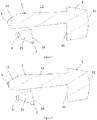
- the present disclosure provides a vehicle light optical element assembly, including a low-beam primary optical element 1, a high-beam primary optical element 2 provided below the low-beam primary optical element 1, and a lens 3 provided at the front end of the low-beam primary optical element 1 and/or the high-beam primary optical element 2.
- the low-beam primary optical element 1 and/or the high-beam primary optical element 2 are/is integrated with the lens 3; and the low-beam primary optical element 1 and the high-beam primary optical element 2 are suitable for focusing and collimating light and then forming a low-beam lighting light shape and a high-beam lighting light shape via the lens 3.
- the vehicle light optical element assembly of the present disclosure mainly has three basic structure solutions: First, the low-beam primary optical element 1 and the lens 3 are integrated, that is, a light-exiting surface of the low-beam primary optical element 1 and a light-incidence surface of the lens 3 are coplanar, and the high-beam primary optical element 2 is provided below the low-beam primary optical element 1. Second, the high-beam primary optical element 2 and the lens 3 are integrated, that is, a light-exiting surface of the high-beam primary optical element 2 and the light-incidence surface of the lens 3 are coplanar, and the low-beam primary optical element 1 is provided above the high-beam primary optical element 2.
- the lens 3 is simultaneously integrated with the low-beam primary optical element 1 and the high-beam primary optical element 2, that is, the light-incidence surface of the lens 3 is coplanar with the light-exiting surface of the low-beam primary optical element 1 and the light-exiting surface of the high-beam primary optical element 2, and the high-beam primary optical element 2 is provided below the low-beam primary optical element 1.
- This setting has the advantages that a space occupied by the vehicle light optical element assembly in a vehicle lighting device and the size of the vehicle lighting device are reduced without affecting a light-exiting effect and the light-exiting efficiency; moreover, the low-beam primary optical element 1 and/or the high-beam primary optical element 2 and the lens 3 are made into a whole, so that the number of parts can be reduced, the positioning and installation error between original parts can also be reduced, and the accuracy of an optical system of the vehicle lighting device is improved.
- the low-beam primary optical element 1 and/or the high-beam primary optical element 2 and the lens 3 in the present disclosure are made into a whole, but this does not affect the formed automobile lamp light shape. Both the automobile lamp light shape in the low-beam mode as shown in Figure 12 and the automobile lamp light shape in the high-beam mode as shown in Figure 13 can meet an automobile lamp lighting requirement.
- the lens 3 includes a lens light-incidence part 31 and a lens light-exiting part 32; the lens light-incidence part 31 is a plane, a backwards protruding curved surface or a forwards protruding curved surface; and the light-exiting part 32 is a forwards protruding curved surface.
- the low-beam primary optical element 1 sequentially, from back to front, includes at least one low-beam condensation part 11 and a low-beam light passing part 12; the low-beam light passing part 12 and the lens light-incidence part 31 are integrated; and a front edge of the lower surface of the low-beam light passing part 12 is formed into a low-beam cut-off line structure 13.
- the high-beam primary optical element 2 includes at least one high-beam condensation part 21; a high-beam light-exiting surface 24 is formed at the front end of the high-beam condensation part 21; and when there are a plurality of high-beam condensation parts 21, a shared high-beam light-exiting surface 24 is formed at the front ends of the plurality of high-beam condensation parts 21.
- the front edge of the lower surface of the low-beam light passing part 12 is formed into the low-beam cut-off line structure 13, and the shape of the low-beam cut-off line structure 13 matches the shape of a low-beam cut-off line 8.
- the light passes through the low-beam light passing part 12 and then enters the lens 3, so that a low-beam lighting light shape having the low-beam cut-off line 8 can be formed through the low-beam cut-off line structure 13.
- the light after exiting from the high-beam light-exiting surface 24 of the high-beam primary optical element 2 and then passing through the lens 3, the light can form a high-beam lighting light shape; part of the light exiting from the high-beam primary optical element 2 is emitted to the low-beam cut-off line structure 13, and is projected by the lens 3 to form a high-beam cut-off line; and at this time, the high-beam cut-off line overlaps the low-beam cut-off line 8, and the low-beam lighting light shape and the high-beam lighting light shape are well engaged.
- the high-beam primary optical element 2 sequentially, from back to front, includes at least one high-beam condensation part 21 and a high-beam light passing part 22; the high-beam light passing part 22 and the lens light-incidence part 31 are integrated; and a front edge of the upper surface of the high-beam light passing part 22 is formed into a high-beam cut-off line structure 23.
- the low-beam primary optical element 1 includes at least one low-beam condensation part 11; a low-beam light-exiting surface 14 is formed at the front end of the low-beam condensation part 11; and when there are a plurality of low-beam condensation parts 11, a shared low-beam light-exiting surface 14 is formed at the front ends of the plurality of low-beam condensation parts 11.
- the front edge of the upper surface of the high-beam light passing part 22 is formed into the high-beam cut-off line structure 23, and the shape of the high-beam cut-off line structure 23 matches the shape of the low-beam cut-off line 8.
- the light passes through the high-beam light passing part 22 and then enters the lens 3, so that a high-beam lighting light shape having the high-beam cut-off line can be formed through the high-beam cut-off line structure 23.
- the light after exiting from the low-beam light-exiting surface 14 of the low-beam primary optical element 1 and then passing through the lens 3, the light can form a low-beam lighting light shape; part of the light exiting from the low-beam primary optical element 1 is emitted to the high-beam cut-off line structure 23, and is projected by the lens 3 to form the low-beam cut-off line 8; and at this time, the low-beam cut-off line 8 overlaps the high-beam cut-off line, and the low-beam lighting light shape and the high-beam lighting light shape are well engaged.
- a corresponding low-beam cut-off line structure may be provided on the light-exiting surface of the low-beam primary optical element 1.
- one of the low-beam primary optical element 1 and the high-beam primary optical element 2 is not connected to the lens 3; furthermore, this optical element omits a longer light passing part, and directly forms the light-exiting surface at the front end of the condensation part, so that while it is ensured that the low-beam lighting light shape or the high-beam lighting light shape corresponding thereto can be realized, materials can be saved, and the weight of the vehicle lighting device can be reduced.
- the light and shade cut-off line is a boundary line presenting a visibly perceptible change in light and shade after a light beam is projected onto a light distribution screen.
- the low-beam cut-off line 8 refers to an upper boundary of the low-beam lighting light shape
- the high-beam cut-off line refers to a lower boundary of the high-beam lighting light shape.
- Different countries have different regulations on the shape of the low-beam cut-off line 8.
- the high-beam cut-off line shall theoretically overlap the low-beam cut-off line 8 or not be provided.
- the light distribution screen refers to a vertical screen disposed at 25 m in front of a vehicle.
- the low-beam primary optical element 1 sequentially, from back to front, includes at least one low-beam condensation part 11 and a low-beam light passing part 12.
- the high-beam primary optical element 2 sequentially, from back to front, includes at least one high-beam condensation part 21 and a high-beam light passing part 22.
- the low-beam light passing part 12 and the high-beam light passing part 22 are integrated with the lens light-incidence part 31; the front edge of the lower surface of the low-beam light passing part 12 is formed into a low-beam cut-off line structure 13, and the front edge of the upper surface of the high-beam light passing part 22 is formed into a high-beam cut-off line structure 23; and a wedge-shaped gap 4 is formed between the low-beam light passing part 12 and the high-beam light passing part 22.
- the low-beam primary optical element 1 and the high-beam primary optical element 2 may also be simultaneously integrated with the lens 3.
- the front edge of the lower surface of the low-beam light passing part 12 is formed into the low-beam cut-off line structure 13
- the front edge of the upper surface of the high-beam light passing part 22 is formed into the high-beam cut-off line structure 23.
- the low-beam cut-off line structure 13 and the high-beam cut-off line structure 23 will not overlap, thus causing a gap existing between the low-beam cut-off line 8 having the low-beam lighting light shape and the high-beam cut-off line having the high-beam lighting light shape, so that the low-beam lighting light shape and the high-beam lighting light shape cannot be well engaged.
- This phenomenon may be made up for through a light distribution means.
- the low-beam primary optical element 1, the high-beam primary optical element 2 and the lens 3 in the structural form are made into an integrated structure, so that the positioning and installation error is greatly reduced, and low-beam light shape and high-beam light shape with higher accuracy can be thus formed.
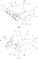
- a plurality of low-beam condensation parts 11 are provided in a left-right direction, and a plurality of high-beam condensation parts 21 are provided in a left-right direction.
- the low-beam condensation parts 11 and the high-beam condensation parts 21 of the present disclosure are both of condensation cup structures, but the low-beam condensation parts 11 and the high-beam condensation parts 21 of the present disclosure are not limited to this structure and arrangement mode. They may also be of condensation cup structures or other condensation structures provided into a matrix, or may further be of independent condensation cup structures or other condensation structures. These situations all fall within the protection scope of the present disclosure.
- the low-beam condensation part 11 is of a condensation cup structure or a protrusion structure which protrudes towards the back. More preferably, the high-beam condensation part 21 is of a condensation cup structure or a protrusion structure which protrudes towards the back.
- the low-beam condensation part 11 and the high-beam condensation part 21 play a role in focusing and collimating light emitted by light sources, so that the low-beam condensation part 11 and the high-beam condensation part 21 may be set to be of the condensation cup structures according to their functional requirements, or may also be of the protrusion structures which protrude towards the back, or may further be of pyramid structures that protrude towards the back, or may further be of other structures, as long as they can satisfy a function of focusing and collimating the light. These situations all fall within the protection scope of the present disclosure.
- the back end of the condensation cup structure is provided with a concave cavity; the bottom of the concave cavity is provided with a protrusion; and an external contour surface of the condensation cup structure is of a curved structure having an aperture that is gradually increased from the back end to the front end.
- the condensation cup structure is solid, a light-incidence surface of which is a plane, a convex curved surface or a concave curved surface; and the external contour surface of the condensation cup structure is of a curved structure having an aperture that is gradually increased from the back end to the front end.
- the condensation cup structure may be provided with a concave cavity, or may be solid. Both types of the condensation cup structures can meet the light focusing and collimation effect.
- the present disclosure further provides a vehicle lighting device 7.
- the vehicle lighting device 7 includes low-beam light sources 5, high-beam light sources 6, and the vehicle light optical element assembly according to any one of the above-mentioned technical solutions.
- the low-beam light sources 5 are in one-to-one correspondence to the low-beam condensation parts 11, and the high-beam light sources 6 are in one-to-one correspondence to the high-beam condensation parts 21.
- the vehicle lighting device 7 further includes a low-beam circuit board and a high-beam circuit board; the low-beam light sources 5 are provided on the low-beam circuit board; and the high-beam light sources are provided on the high-beam circuit board.
- the vehicle lighting device 7 further includes a circuit board, and the low-beam light sources 5 and the high-beam light sources 6 are both provided on the circuit board.
- the low-beam light sources 5 and the high-beam light sources 6 need to be installed on the circuit board.
- the vehicle light optical element assembly in the vehicle lighting device 7 of the present disclosure is smaller in size, so that the vehicle lighting device 7 of the present disclosure is gradually developing towards minimization.
- the minimization of the vehicle lighting device 7 is conductive to arranging the vehicle lighting device 7 in a limited space of a lamp body of a vehicle light at will, and can realize different light-exiting modeling surfaces by means of different arrangement forms.
- the present disclosure further provides a vehicle light, including at least one vehicle lighting device 7 according to at least one of the technical solutions.
- the vehicle light of the present disclosure includes three vehicle lighting devices 7. These vehicle lighting devices 7 are usually provided according to one straight line or curved line, or provided according to a matrix form. This is set according to an actual light-exiting requirement and modeling requirement of the vehicle light.
- the present disclosure further provides a vehicle, including the vehicle light in the above-mentioned technical solution.
- the vehicle light optical element assembly of the present disclosure includes the low-beam primary optical element 1, the high-beam primary optical element 2 provided below the low-beam primary optical element 1, and the lens 3 provided at the front end of the low-beam primary optical element 1 and/or the high-beam primary optical element 2.
- the low-beam primary optical element 1 and/or the high-beam primary optical element 2 are/is integrated with the lens 3; and the low-beam primary optical element 1 and the high-beam primary optical element 2 are suitable for focusing and collimating light and then forming a low-beam lighting light shape and a high-beam lighting light shape via the lens 3.
- the size of the vehicle light optical element assembly of the present disclosure can be effectively reduced without affecting high-beam lighting and low-beam lighting; and moreover, the positioning and installation error can also be reduced, and the optical system accuracy is improved.
Landscapes
- Engineering & Computer Science (AREA)
- General Engineering & Computer Science (AREA)
- Physics & Mathematics (AREA)
- Microelectronics & Electronic Packaging (AREA)
- Optics & Photonics (AREA)
- Mechanical Engineering (AREA)
- Non-Portable Lighting Devices Or Systems Thereof (AREA)
- Fastening Of Light Sources Or Lamp Holders (AREA)
- Planar Illumination Modules (AREA)
Applications Claiming Priority (2)
| Application Number | Priority Date | Filing Date | Title |
|---|---|---|---|
| CN202020281769.6U CN212132313U (zh) | 2020-03-09 | 2020-03-09 | 车灯光学元件组件、车辆照明装置、车灯和车辆 |
| PCT/CN2020/129309 WO2021179664A1 (zh) | 2020-03-09 | 2020-11-17 | 车灯光学元件组件、车辆照明装置、车灯和车辆 |
Publications (3)
| Publication Number | Publication Date |
|---|---|
| EP4006408A1 true EP4006408A1 (de) | 2022-06-01 |
| EP4006408A4 EP4006408A4 (de) | 2022-11-09 |
| EP4006408B1 EP4006408B1 (de) | 2024-05-29 |
Family
ID=73673308
Family Applications (1)
| Application Number | Title | Priority Date | Filing Date |
|---|---|---|---|
| EP20924803.8A Active EP4006408B1 (de) | 2020-03-09 | 2020-11-17 | Fahrzeugleuchte, fahrzeugbeleuchtungsvorrichtung, fahrzeugleuchte und fahrzeug |
Country Status (7)
| Country | Link |
|---|---|
| US (1) | US11927317B2 (de) |
| EP (1) | EP4006408B1 (de) |
| JP (1) | JP7433421B2 (de) |
| KR (1) | KR20220044799A (de) |
| CN (1) | CN212132313U (de) |
| MX (1) | MX2022000228A (de) |
| WO (1) | WO2021179664A1 (de) |
Family Cites Families (15)
| Publication number | Priority date | Publication date | Assignee | Title |
|---|---|---|---|---|
| JP4335785B2 (ja) | 2004-02-27 | 2009-09-30 | スタンレー電気株式会社 | 車両用灯具 |
| US9719648B2 (en) | 2015-09-09 | 2017-08-01 | Witslight Technology Corporation Limited | Automobile lamp having a lighting pattern with a light-and-shade contrast |
| FR3041738B1 (fr) * | 2015-09-28 | 2020-01-17 | Valeo Vision | Element optique primaire pour module lumineux de vehicule automobile |
| AT518109B1 (de) | 2016-01-14 | 2017-11-15 | Zkw Group Gmbh | Beleuchtungseinheit für einen Kraftfahrzeugscheinwerfer zum Erzeugen eines Lichtbündels mit Hell-Dunkel-Grenze |
| FR3050011A1 (fr) * | 2016-04-11 | 2017-10-13 | Valeo Vision | Module d'emission d'un faisceau lumineux pour projecteur de vehicule automobile |
| JP6747886B2 (ja) | 2016-06-23 | 2020-08-26 | スタンレー電気株式会社 | 車両用灯具 |
| FR3056688B1 (fr) * | 2016-09-26 | 2018-11-02 | Valeo Vision | Module d'eclairage bi-fonction en materiau transparent |
| JP6857490B2 (ja) | 2016-12-12 | 2021-04-14 | 株式会社小糸製作所 | 車両用前照灯 |
| CN109140377B (zh) | 2018-08-03 | 2020-11-24 | 常熟理工学院 | 一种汽车前照灯单元 |
| CN110953551A (zh) * | 2018-09-27 | 2020-04-03 | 法雷奥照明湖北技术中心有限公司 | 光学元件、光学模块和车辆 |
| CN109268774A (zh) | 2018-10-25 | 2019-01-25 | 华域视觉科技(上海)有限公司 | 一种双排矩阵式照明模组及其辅助照明方法 |
| CN209801362U (zh) | 2019-03-29 | 2019-12-17 | 曼德电子电器有限公司 | 车辆近光配光结构 |
| CN209782494U (zh) | 2019-04-25 | 2019-12-13 | 江西省绿野汽车照明有限公司 | 棱镜全反射式近光模组以及车灯 |
| CN210601445U (zh) * | 2019-10-25 | 2020-05-22 | 华域视觉科技(上海)有限公司 | 一种车灯光学元件 |
| CN210740266U (zh) * | 2019-10-25 | 2020-06-12 | 华域视觉科技(上海)有限公司 | 车灯光学元件 |
-
2020
- 2020-03-09 CN CN202020281769.6U patent/CN212132313U/zh active Active
- 2020-11-17 MX MX2022000228A patent/MX2022000228A/es unknown
- 2020-11-17 US US17/760,905 patent/US11927317B2/en active Active
- 2020-11-17 JP JP2022520919A patent/JP7433421B2/ja active Active
- 2020-11-17 KR KR1020227007827A patent/KR20220044799A/ko not_active Application Discontinuation
- 2020-11-17 WO PCT/CN2020/129309 patent/WO2021179664A1/zh unknown
- 2020-11-17 EP EP20924803.8A patent/EP4006408B1/de active Active
Also Published As
| Publication number | Publication date |
|---|---|
| EP4006408B1 (de) | 2024-05-29 |
| KR20220044799A (ko) | 2022-04-11 |
| EP4006408A4 (de) | 2022-11-09 |
| MX2022000228A (es) | 2022-02-03 |
| CN212132313U (zh) | 2020-12-11 |
| JP2022550614A (ja) | 2022-12-02 |
| WO2021179664A1 (zh) | 2021-09-16 |
| US20220349542A1 (en) | 2022-11-03 |
| JP7433421B2 (ja) | 2024-02-19 |
| US11927317B2 (en) | 2024-03-12 |
Similar Documents
| Publication | Publication Date | Title |
|---|---|---|
| EP2366940B1 (de) | Projektionsschweinwerfer für Motorräder | |
| US20070177400A1 (en) | Vehicle lighting device | |
| CN211822197U (zh) | 前照灯模组、前照灯及车辆 | |
| CN211694701U (zh) | 前照灯光学元件、前照灯模组、车灯及车辆 | |
| US10578268B2 (en) | Smart headlight | |
| CN209893297U (zh) | 一种车辆远光灯模组 | |
| EP3885644B1 (de) | Optisches abblendlichtmodul, abblendlichtbeleuchtungsmodul, fahrzeugleuchte und fahrzeug | |
| JP2021535567A (ja) | 照明モジュール、車両用ランプおよび車両 | |
| EP4006408A1 (de) | Fahrzeugleuchte, fahrzeugbeleuchtungsvorrichtung, fahrzeugleuchte und fahrzeug | |
| CN212132312U (zh) | 初级光学元件组件、车辆照明装置、车灯和车辆 | |
| CN212390299U (zh) | 用于车辆近光灯的光学元件、近光照明装置、车灯和车辆 | |
| US11927318B2 (en) | Headlamp optical element with III-region light shape forming structure | |
| CN210462861U (zh) | 车灯模组及反射结构 | |
| CN205208372U (zh) | 一种具有分光结构的光线收集装置及前照灯 | |
| CN211875908U (zh) | 光学元件、前照灯模组、车灯及车辆 | |
| CN105423216A (zh) | 一种光线收集装置及前照灯 | |
| CN112781001A (zh) | 车灯光学元件、车灯模组和车辆 | |
| CN220582277U (zh) | 一种车灯照明模组和车灯 | |
| JP7300554B2 (ja) | マイクロ車両ライトモジュール及び反射構造 | |
| CN210219615U (zh) | 一种微型车灯模组 | |
| WO2021036216A1 (zh) | 一种微型车灯模组 | |
| CN213542362U (zh) | 车灯光学组件、车灯模组和车辆 | |
| CN211875914U (zh) | 用于车辆远光灯的光学元件、远光照明装置、车灯和车辆 | |
| CN220911199U (zh) | 近光灯模组、近光灯和车辆 | |
| EP4123218A1 (de) | Mehrpixel-hochstrahlsystem, fahrzeuglampe und fahrzeug |
Legal Events
| Date | Code | Title | Description |
|---|---|---|---|
| STAA | Information on the status of an ep patent application or granted ep patent |
Free format text: STATUS: THE INTERNATIONAL PUBLICATION HAS BEEN MADE |
|
| PUAI | Public reference made under article 153(3) epc to a published international application that has entered the european phase |
Free format text: ORIGINAL CODE: 0009012 |
|
| STAA | Information on the status of an ep patent application or granted ep patent |
Free format text: STATUS: REQUEST FOR EXAMINATION WAS MADE |
|
| 17P | Request for examination filed |
Effective date: 20220225 |
|
| AK | Designated contracting states |
Kind code of ref document: A1 Designated state(s): AL AT BE BG CH CY CZ DE DK EE ES FI FR GB GR HR HU IE IS IT LI LT LU LV MC MK MT NL NO PL PT RO RS SE SI SK SM TR |
|
| A4 | Supplementary search report drawn up and despatched |
Effective date: 20221007 |
|
| RIC1 | Information provided on ipc code assigned before grant |
Ipc: F21S 41/20 20180101ALI20220930BHEP Ipc: F21S 41/147 20180101ALI20220930BHEP Ipc: F21Y 115/10 20160101ALI20220930BHEP Ipc: F21V 17/10 20060101ALI20220930BHEP Ipc: F21S 41/25 20180101AFI20220930BHEP |
|
| DAV | Request for validation of the european patent (deleted) | ||
| DAX | Request for extension of the european patent (deleted) | ||
| STAA | Information on the status of an ep patent application or granted ep patent |
Free format text: STATUS: EXAMINATION IS IN PROGRESS |
|
| 17Q | First examination report despatched |
Effective date: 20230616 |
|
| REG | Reference to a national code |
Ref country code: DE Ref legal event code: R079 Ref document number: 602020031835 Country of ref document: DE Free format text: PREVIOUS MAIN CLASS: F21S0041250000 Ipc: F21S0041143000 Ref country code: DE Ref legal event code: R079 Free format text: PREVIOUS MAIN CLASS: F21S0041250000 Ipc: F21S0041143000 |
|
| RIC1 | Information provided on ipc code assigned before grant |
Ipc: F21S 41/24 20180101ALI20231030BHEP Ipc: F21S 41/20 20180101ALI20231030BHEP Ipc: F21S 41/147 20180101ALI20231030BHEP Ipc: F21S 41/43 20180101ALI20231030BHEP Ipc: F21S 41/27 20180101ALI20231030BHEP Ipc: F21S 41/255 20180101ALI20231030BHEP Ipc: F21S 41/151 20180101ALI20231030BHEP Ipc: F21S 41/143 20180101AFI20231030BHEP |
|
| GRAP | Despatch of communication of intention to grant a patent |
Free format text: ORIGINAL CODE: EPIDOSNIGR1 |
|
| STAA | Information on the status of an ep patent application or granted ep patent |
Free format text: STATUS: GRANT OF PATENT IS INTENDED |
|
| INTG | Intention to grant announced |
Effective date: 20231222 |
|
| GRAS | Grant fee paid |
Free format text: ORIGINAL CODE: EPIDOSNIGR3 |
|
| GRAA | (expected) grant |
Free format text: ORIGINAL CODE: 0009210 |
|
| STAA | Information on the status of an ep patent application or granted ep patent |
Free format text: STATUS: THE PATENT HAS BEEN GRANTED |