EP4006391A1 - Mehrwegeventil für eine steuerung eines kältemittelkreislaufes - Google Patents
Mehrwegeventil für eine steuerung eines kältemittelkreislaufes Download PDFInfo
- Publication number
- EP4006391A1 EP4006391A1 EP21203742.8A EP21203742A EP4006391A1 EP 4006391 A1 EP4006391 A1 EP 4006391A1 EP 21203742 A EP21203742 A EP 21203742A EP 4006391 A1 EP4006391 A1 EP 4006391A1
- Authority
- EP
- European Patent Office
- Prior art keywords
- way valve
- housing
- rotary slide
- arrangement
- connection
- Prior art date
- Legal status (The legal status is an assumption and is not a legal conclusion. Google has not performed a legal analysis and makes no representation as to the accuracy of the status listed.)
- Pending
Links
- 239000003507 refrigerant Substances 0.000 title claims abstract description 55
- 230000001105 regulatory effect Effects 0.000 claims abstract description 28
- 238000003780 insertion Methods 0.000 claims abstract description 11
- 230000037431 insertion Effects 0.000 claims abstract description 11
- 230000001276 controlling effect Effects 0.000 claims abstract description 6
- 238000005057 refrigeration Methods 0.000 claims abstract description 5
- 230000000712 assembly Effects 0.000 claims description 18
- 238000000429 assembly Methods 0.000 claims description 18
- 238000001816 cooling Methods 0.000 description 6
- 238000007789 sealing Methods 0.000 description 5
- 239000012530 fluid Substances 0.000 description 4
- 238000009434 installation Methods 0.000 description 4
- 238000010276 construction Methods 0.000 description 3
- 238000005457 optimization Methods 0.000 description 3
- 239000002826 coolant Substances 0.000 description 2
- 230000004913 activation Effects 0.000 description 1
- 238000004378 air conditioning Methods 0.000 description 1
- 230000005540 biological transmission Effects 0.000 description 1
- 239000000919 ceramic Substances 0.000 description 1
- 230000000295 complement effect Effects 0.000 description 1
- 238000011161 development Methods 0.000 description 1
- 230000018109 developmental process Effects 0.000 description 1
- 238000000605 extraction Methods 0.000 description 1
- 230000002349 favourable effect Effects 0.000 description 1
- 238000010438 heat treatment Methods 0.000 description 1
- 239000002184 metal Substances 0.000 description 1
- 230000000717 retained effect Effects 0.000 description 1
- 230000007704 transition Effects 0.000 description 1
Images


Classifications
-
- F—MECHANICAL ENGINEERING; LIGHTING; HEATING; WEAPONS; BLASTING
- F25—REFRIGERATION OR COOLING; COMBINED HEATING AND REFRIGERATION SYSTEMS; HEAT PUMP SYSTEMS; MANUFACTURE OR STORAGE OF ICE; LIQUEFACTION SOLIDIFICATION OF GASES
- F25B—REFRIGERATION MACHINES, PLANTS OR SYSTEMS; COMBINED HEATING AND REFRIGERATION SYSTEMS; HEAT PUMP SYSTEMS
- F25B41/00—Fluid-circulation arrangements
- F25B41/20—Disposition of valves, e.g. of on-off valves or flow control valves
- F25B41/24—Arrangement of shut-off valves for disconnecting a part of the refrigerant cycle, e.g. an outdoor part
-
- F—MECHANICAL ENGINEERING; LIGHTING; HEATING; WEAPONS; BLASTING
- F16—ENGINEERING ELEMENTS AND UNITS; GENERAL MEASURES FOR PRODUCING AND MAINTAINING EFFECTIVE FUNCTIONING OF MACHINES OR INSTALLATIONS; THERMAL INSULATION IN GENERAL
- F16K—VALVES; TAPS; COCKS; ACTUATING-FLOATS; DEVICES FOR VENTING OR AERATING
- F16K11/00—Multiple-way valves, e.g. mixing valves; Pipe fittings incorporating such valves
- F16K11/02—Multiple-way valves, e.g. mixing valves; Pipe fittings incorporating such valves with all movable sealing faces moving as one unit
- F16K11/06—Multiple-way valves, e.g. mixing valves; Pipe fittings incorporating such valves with all movable sealing faces moving as one unit comprising only sliding valves, i.e. sliding closure elements
- F16K11/072—Multiple-way valves, e.g. mixing valves; Pipe fittings incorporating such valves with all movable sealing faces moving as one unit comprising only sliding valves, i.e. sliding closure elements with pivoted closure members
- F16K11/074—Multiple-way valves, e.g. mixing valves; Pipe fittings incorporating such valves with all movable sealing faces moving as one unit comprising only sliding valves, i.e. sliding closure elements with pivoted closure members with flat sealing faces
-
- F—MECHANICAL ENGINEERING; LIGHTING; HEATING; WEAPONS; BLASTING
- F16—ENGINEERING ELEMENTS AND UNITS; GENERAL MEASURES FOR PRODUCING AND MAINTAINING EFFECTIVE FUNCTIONING OF MACHINES OR INSTALLATIONS; THERMAL INSULATION IN GENERAL
- F16K—VALVES; TAPS; COCKS; ACTUATING-FLOATS; DEVICES FOR VENTING OR AERATING
- F16K11/00—Multiple-way valves, e.g. mixing valves; Pipe fittings incorporating such valves
- F16K11/10—Multiple-way valves, e.g. mixing valves; Pipe fittings incorporating such valves with two or more closure members not moving as a unit
- F16K11/20—Multiple-way valves, e.g. mixing valves; Pipe fittings incorporating such valves with two or more closure members not moving as a unit operated by separate actuating members
- F16K11/22—Multiple-way valves, e.g. mixing valves; Pipe fittings incorporating such valves with two or more closure members not moving as a unit operated by separate actuating members with an actuating member for each valve, e.g. interconnected to form multiple-way valves
-
- F—MECHANICAL ENGINEERING; LIGHTING; HEATING; WEAPONS; BLASTING
- F16—ENGINEERING ELEMENTS AND UNITS; GENERAL MEASURES FOR PRODUCING AND MAINTAINING EFFECTIVE FUNCTIONING OF MACHINES OR INSTALLATIONS; THERMAL INSULATION IN GENERAL
- F16K—VALVES; TAPS; COCKS; ACTUATING-FLOATS; DEVICES FOR VENTING OR AERATING
- F16K27/00—Construction of housing; Use of materials therefor
- F16K27/04—Construction of housing; Use of materials therefor of sliding valves
- F16K27/041—Construction of housing; Use of materials therefor of sliding valves cylindrical slide valves
-
- F—MECHANICAL ENGINEERING; LIGHTING; HEATING; WEAPONS; BLASTING
- F16—ENGINEERING ELEMENTS AND UNITS; GENERAL MEASURES FOR PRODUCING AND MAINTAINING EFFECTIVE FUNCTIONING OF MACHINES OR INSTALLATIONS; THERMAL INSULATION IN GENERAL
- F16K—VALVES; TAPS; COCKS; ACTUATING-FLOATS; DEVICES FOR VENTING OR AERATING
- F16K27/00—Construction of housing; Use of materials therefor
- F16K27/04—Construction of housing; Use of materials therefor of sliding valves
- F16K27/044—Construction of housing; Use of materials therefor of sliding valves slide valves with flat obturating members
- F16K27/045—Construction of housing; Use of materials therefor of sliding valves slide valves with flat obturating members with pivotal obturating members
-
- F—MECHANICAL ENGINEERING; LIGHTING; HEATING; WEAPONS; BLASTING
- F25—REFRIGERATION OR COOLING; COMBINED HEATING AND REFRIGERATION SYSTEMS; HEAT PUMP SYSTEMS; MANUFACTURE OR STORAGE OF ICE; LIQUEFACTION SOLIDIFICATION OF GASES
- F25B—REFRIGERATION MACHINES, PLANTS OR SYSTEMS; COMBINED HEATING AND REFRIGERATION SYSTEMS; HEAT PUMP SYSTEMS
- F25B41/00—Fluid-circulation arrangements
- F25B41/20—Disposition of valves, e.g. of on-off valves or flow control valves
-
- F—MECHANICAL ENGINEERING; LIGHTING; HEATING; WEAPONS; BLASTING
- F25—REFRIGERATION OR COOLING; COMBINED HEATING AND REFRIGERATION SYSTEMS; HEAT PUMP SYSTEMS; MANUFACTURE OR STORAGE OF ICE; LIQUEFACTION SOLIDIFICATION OF GASES
- F25B—REFRIGERATION MACHINES, PLANTS OR SYSTEMS; COMBINED HEATING AND REFRIGERATION SYSTEMS; HEAT PUMP SYSTEMS
- F25B41/00—Fluid-circulation arrangements
- F25B41/40—Fluid line arrangements
- F25B41/42—Arrangements for diverging or converging flows, e.g. branch lines or junctions
-
- F—MECHANICAL ENGINEERING; LIGHTING; HEATING; WEAPONS; BLASTING
- F16—ENGINEERING ELEMENTS AND UNITS; GENERAL MEASURES FOR PRODUCING AND MAINTAINING EFFECTIVE FUNCTIONING OF MACHINES OR INSTALLATIONS; THERMAL INSULATION IN GENERAL
- F16K—VALVES; TAPS; COCKS; ACTUATING-FLOATS; DEVICES FOR VENTING OR AERATING
- F16K11/00—Multiple-way valves, e.g. mixing valves; Pipe fittings incorporating such valves
- F16K11/10—Multiple-way valves, e.g. mixing valves; Pipe fittings incorporating such valves with two or more closure members not moving as a unit
- F16K11/20—Multiple-way valves, e.g. mixing valves; Pipe fittings incorporating such valves with two or more closure members not moving as a unit operated by separate actuating members
- F16K11/207—Multiple-way valves, e.g. mixing valves; Pipe fittings incorporating such valves with two or more closure members not moving as a unit operated by separate actuating members with two handles or actuating mechanisms at opposite sides of the housing
-
- F—MECHANICAL ENGINEERING; LIGHTING; HEATING; WEAPONS; BLASTING
- F25—REFRIGERATION OR COOLING; COMBINED HEATING AND REFRIGERATION SYSTEMS; HEAT PUMP SYSTEMS; MANUFACTURE OR STORAGE OF ICE; LIQUEFACTION SOLIDIFICATION OF GASES
- F25B—REFRIGERATION MACHINES, PLANTS OR SYSTEMS; COMBINED HEATING AND REFRIGERATION SYSTEMS; HEAT PUMP SYSTEMS
- F25B2313/00—Compression machines, plants or systems with reversible cycle not otherwise provided for
- F25B2313/027—Compression machines, plants or systems with reversible cycle not otherwise provided for characterised by the reversing means
- F25B2313/02741—Compression machines, plants or systems with reversible cycle not otherwise provided for characterised by the reversing means using one four-way valve
-
- F—MECHANICAL ENGINEERING; LIGHTING; HEATING; WEAPONS; BLASTING
- F25—REFRIGERATION OR COOLING; COMBINED HEATING AND REFRIGERATION SYSTEMS; HEAT PUMP SYSTEMS; MANUFACTURE OR STORAGE OF ICE; LIQUEFACTION SOLIDIFICATION OF GASES
- F25B—REFRIGERATION MACHINES, PLANTS OR SYSTEMS; COMBINED HEATING AND REFRIGERATION SYSTEMS; HEAT PUMP SYSTEMS
- F25B41/00—Fluid-circulation arrangements
- F25B41/20—Disposition of valves, e.g. of on-off valves or flow control valves
- F25B41/26—Disposition of valves, e.g. of on-off valves or flow control valves of fluid flow reversing valves
Definitions
- the invention relates to a multi-way valve for controlling a refrigerant circuit with a refrigeration system with a heat pump function.
- a multi-way valve for controlling a refrigerant circuit comprises a housing in which a rotary slide arrangement is provided, which actuates various switching positions via a shaft which is driven by a motor.
- the housing includes a first inlet opening which is connected to a regulation space by a first fluid channel.
- a second connection opening in the housing is connected to a second fluid channel to the regulating space.
- a third and fourth fluid channel leads from the control space to an outlet opening.
- the invention is based on the object of proposing a multi-way valve which enables a simple structure and individual activation of a number of switching positions for a refrigerant circuit.
- a multi-way valve for controlling the refrigerant circuit of the refrigeration system with a heat pump function which includes a housing that has two opposite end faces or two end faces that are associated with one another, each of which includes an insertion opening which is adjoined by a control space, in each of which a multi-way valve arrangement can be used, which comprises at least one base body and a rotary valve assembly.
- the housing has a connection opening assigned to the control space and at least two further connection openings, which are provided between the two rotary valve assemblies of the multi-way valve assemblies.
- the housing can be made in one piece.
- This multi-way valve has the advantage that two multi-way valve arrangements can be inserted opposite one another in the same housing.
- the design of the multi-way valve arrangements can be simplified, and it is nevertheless possible that, for example, up to six switching positions and preferably one service position can be set and controlled.
- two mutually opposite regulating spaces in the housing of the multi-way valve are aligned in a common longitudinal axis.
- the multi-way valve arrangements that can be used in each case in the control space are preferably aligned as mirror images of one another in the housing.
- the construction and in particular the arrangement of channels between the two regulating spaces can be simplified.
- the two longitudinal axes of the adjustment spaces are aligned at an angle of between 90° and 179°, preferably 135° and 179°, to one another.
- each insertion opening in the housing is preferably closed by a base body of the multi-way valve arrangement.
- a pressure-tight arrangement is created after this multi-way valve arrangement has been inserted into the housing.
- the rotary slide assemblies of the multi-way valve assemblies are preferably each driven by a shaft, and the shafts preferably lie on a common axis. This allows a simplified construction of the multi-way valve.
- the mutually opposite regulation spaces in the housing are preferably connected to two channels arranged coaxially to the longitudinal axis of the housing. These channels preferably extend between the two rotary valve arrangements arranged in the control spaces.
- connection opening into the regulation space is preferably aligned tangentially to the regulation space.
- Connection is thus decentralized to the control room.
- the at least one connection opening into the control space and the at least one connection provided between the two control spaces are aligned in the same direction on the housing.
- the housing preferably has a rectangular cross-section at least in sections and the at least one connection opening into the control space, the connections provided between the two control spaces and opening into the channels being aligned with the same side surface of the housing.
- the at least one connection for the further adjustment space is preferably aligned with an adjacent or opposite side face of the housing. This enables an improved installation situation and the option of connecting to other components of the refrigerant circuit, such as a chiller for battery cooling or an evaporator for air conditioning.
- Each multi-way valve arrangement of the multi-way valve preferably has a drive which drives a shaft which actuates the rotary slide arrangement.
- each multi-way valve arrangement can be activated in the respective switch positions and preferably coordinated with one another.
- a common control is preferably provided, by means of which the two multi-way valve arrangements can be controlled.
- the drives of the multi-way valve arrangements are preferably designed as flat, rectangular housings.
- a longitudinal axis of the housing is oriented differently from the side face of the housing having the plurality of terminals. This enables connection optimization.
- At least one side surface of the housing is preferably free of connections. This can provide an assembly interface.
- the one connection opening out to the control chamber can preferably be controlled as an inlet for the refrigerant in all adjustable switching positions, and the first multi-way valve arrangement is preferably arranged on the high-pressure side of the housing.
- the first multi-way valve arrangement is preferably designed according to the pressure conditions prevailing in the control space.
- the second multi-way valve arrangement opposite the first multi-way valve arrangement is preferably arranged on a low-pressure side of the housing. Since the flow conditions on the low-pressure side of the housing are different from those on the high-pressure side, the rotary slide arrangement of the second multi-way valve arrangement can be adapted accordingly.
- the first and second multi-way valve arrangements preferably have a connection point for the drive and preferably the same drive.
- the base body of the two multi-way valve arrangements can also be designed in the same way.
- first and second multi-way valve arrangement between the base body and the rotary slide arrangement preferably have a driver which is rotatably controlled by the shaft and rotatably controls a respective control disk of the rotary slide arrangement.
- the basic structure of such a rotary slide arrangement can be retained for both multi-way valve arrangements.
- the control disks of the rotary valve arrangement are matched to one another, so that they can rest against one another in a sealing manner in various switching positions without additional seals.
- the first multi-way valve arrangement can be used in the control space and the connection designed as an inlet can be pressurized and the refrigerant is transferred into one channel or the other channel or partially into the two channels and this rotary slide arrangement of the first multi-way valve arrangement by a rotary rotary slide and a fixed rotary slide support is formed, which is preferably positioned under pressure adjacent to the bottom of the control space.
- the second multi-way valve arrangement is preferably constructed differently from the rotary slide arrangement of the first multi-way valve arrangement. This has an adjustment to the pressure gradient and a direction of flow, since the rotary slide support is acted upon first. In this second multi-way valve arrangement, the pressure acts in the opposite direction to the first multi-way valve arrangement.
- the rotary slide support preferably has two connection sockets which can be inserted into sections of the channels and are each sealed off by seals.
- the end faces of the connection sockets pointing towards the channels are preferably provided with insertion bevels.
- the above-described embodiment of the multi-way valve can be used to control up to six different switching positions and preferably one switching position for service operation of the refrigerant circuit.
- Six switching positions are to be understood to mean that the connections are connected to one another in a manner that differs from one another, with settings still being possible in between with regard to the individual flow volumes.
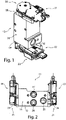
- FIG 1 a perspective view of a multi-way valve 11 is shown.
- This multi-way valve 11 is used to control a refrigerant circuit 12 ( Figures 6 and 13 ) of a refrigeration system with a heat pump function.
- This multi-way valve 11 includes a housing 12 which has, for example, a rectangular cross section.
- This housing 12 has a mounting interface 14 on one end face, in which, for example, bores for attaching fastening elements are provided.
- a connection 16 for a refrigerant supply or discharge is provided on a further side surface.
- a first multi-way valve arrangement 21 and opposite a second multi-way valve arrangement 22 are arranged on one end face 18 and an opposite end face 19 of the housing 12 . Only one drive 23 can be seen on this multi-way valve arrangement 21, 22 in each case. Below are in the sectional views according to Figures 3 to 5 the multi-way valve assemblies 21, 22 described in more detail:
- connections 25, 26, 27 are provided in a further side face of the housing 12. These connections 25, 26, 27 are provided on a side surface which is preferably aligned parallel to a longitudinal axis 24 of the drives 23.
- connections 16 , 25 , 26 , 27 are arranged on a side face of the housing 12 .
- a connection 16, 25, 26, 27 may be provided.
- the number of connections per side surface 12 of the housing and their orientation can be adapted to the installation situation.
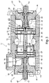
- figure 3 12 is a longitudinal section of the multi-way valve 11 in FIG figure 1 shown.
- the respective drives 23 of the first multi-way valve assembly 21 and second multi-way valve assembly 22 are only partially shown.
- This longitudinal section shows that the housing 12 for the multi-way valve 11 is preferably designed in one piece.
- An insertion opening 29, 30 is provided on each of the end faces 18, 19, to which a regulating space 31, 32 is connected in each case.
- the first connection 25 is assigned to the control space 31 .
- Two channels 34 , 35 are provided between the two regulating spaces 31 , 32 , one channel 34 being connected to the connection 26 and the other channel 35 being connected to the connection 27 .
- the second regulating space 32 facing the first regulating space 31 is connected to the port 16 .
- This multi-way valve 11 accommodates the first multi-way valve arrangement 21 and the second multi-way valve arrangement 22 opposite one another in the housing 12 . These can each be inserted via the insertion openings 29, 30 into the corresponding regulating space 31, 32 and fixed therein via detachable fastening means, not shown in detail.
- the multi-way valve assemblies 21, 22 have an analog structure. These include a base body 41 which can be inserted into the insertion opening 29 , 30 . At least one seal 42 is provided on the outer circumference of the base body in order to seal off this regulating space 31, 32 from the outside. In the base body 41 a shaft 43 is guided in a rotating manner by a shaft bearing 45 .
- a shaft seal 44 which is arranged between the shaft 43 and the base body 41 , seals off the control space.
- a pinion 47 is provided on a front end of the shaft 43 and is drivingly connected to a complementary drive element 48 of the drive 23 ( Figure 4 and Figure 5 ).
- the shaft 43 is connected to a rotary slide arrangement 51, 52.
- the rotary slide assembly 51 of the first multi-way valve assembly 21 preferably differs from the rotary slide assembly 52 of the second multi-way valve assembly 22 and is subsequently in the Figures 4 and 5 described in more detail.
- a driver 53 is provided between the rotary slide assembly 51, 52 and the shaft 44, which is firmly connected to the shaft 43 and controls a rotary movement of a rotary slide 54, 55 relative to a rotary slide support 56, 57 of the rotary slide assembly 52, 53.
- the shaft 43 is, for example, welded to the driver 54, in particular welded with a laser, or soldered, pressed or riveted.
- connection 25 is designed as an inlet for a refrigerant.
- high pressure is present in this first control chamber 31 .
- the first multi-way valve arrangement 21 is provided on the high-pressure side in the control chamber 31 and is designed accordingly.
- connections 26, 27 are provided on the low-pressure side. Furthermore, the second multi-way valve arrangement 22 is arranged in the second control chamber 32 on the low-pressure side.
- the port 16 is designed as an outlet.
- the connections 26, 27, which open into the channels 34, 35, can be controlled both as an inlet and as an outlet, with these being acted upon on the low-pressure side regardless of the control.
- the inlet 25 from the housing 12 into the control space 31 and the connection 16 from the second control space 32 out of the housing 12 are preferably provided eccentrically to the longitudinal axis of the respective multi-way valve arrangement 21 , 22 . These open eccentrically into the regulating spaces 31 , 32 and feed the refrigerant to a rounded section of the base body 41 . This enables a flow-optimized supply and/or removal of the refrigerant. Furthermore, the leading edge of the connection 25 in the control space 31 and an edge between the regulating space 32 and the outlet 16 has an inner chamfer, as a result of which a reduction in the pressure drop between the connection 25 to the regulating space 31 and/or from the regulating space 32 to the connection 16 is made possible.
- the connections 26, 27 are positioned eccentrically to the channels 34, 35.
- the control spaces 31, 32 are opposite one another and aligned with one another in such a way that, after the insertion of the first and second multi-way valve arrangement 21, 22, the longitudinal axes of the shafts 43 preferably lie in a common longitudinal axis.
- the channels 34, 35 are aligned coaxially with the longitudinal axis of the housing 12 and the longitudinal axis of the shafts 43, respectively.
- the longitudinal axes of the shafts 43 can also be aligned parallel to one another in a common housing 12 .
- the longitudinal axes of the two shafts 43 of the multi-way valve arrangement 21, 22 can be arranged at an angle of ⁇ 180° in a common housing 12.
- the adjustment spaces 31, 32 can also be aligned at an angle of 90° or at an angle of 90° to 180°, with the channels 34, 35 having correspondingly streamlined geometries.
- the rotary slide assemblies 51, 52 each have a first rotatable rotary slide 54, 55, which include two through-openings 61, 62, for example. These rotary slides 54, 55 are associated with rotary slide supports 56, 57. These also preferably each have two through-openings 63, 64. By covering or offsetting the first rotary slide 54, 55 relative to the rotary slide support 56, 57, the corresponding through-openings can be blocked and fully released, and individually or both partially opened. This is in the subsequent Figures 7 to 12 and 14 described.
- the respective passage openings 63, 64 in the rotary slide support 56, 57 are aligned with the channels 34, 35.
- the rotary valve 54, 55 and the rotary valve support 56, 57 are preferably made of ceramic. These can also be made of plastic or metal.
- the refrigerant entering via the connection 25 designed as an inlet is supplied either only to the channel 34 or only to the channel 35, for example through the first multi-way valve arrangement 21, or both channels 34, 35 are each supplied proportionately with refrigerant.
- a coolant present in the channel 34 can flow out via the connection 26 designed as an outlet.
- the coolant provided in channel 35 which can be discharged via connection 27 .
- a switching position can also be assumed, so that the connection 16 designed as an outlet discharges the refrigerant.
- FIG 4 is schematically enlarged the first multi-way valve assembly 21 in a further sectional view figure 3 shown.
- the sectional view shown is rotated 90° to that in figure 3 .
- This sectional view shows that this rotary slide support 56 is mounted in relation to the housing 12 in a manner secured against rotation by pins 58 .
- the rotary slide support 56 is held fixed to the housing 12 by a screw connection.
- a seal 59 can be provided for the sealing arrangement of the rotary slide support 56 to the housing 12, as is shown in figure 3 is shown, so that for each passage opening 63, 64 in each case a seal 59 is provided for the sealing arrangement between the housing 12 and the rotary slide support 56.
- the rotary slide 54 has cup-shaped depressions which merge into the through-openings 61 , 62 . As a result, a streamlined arrangement can be created.
- the driver 53 is preferably by at least one, in particular two pins 68 ( figure 3 ) rotatably fixed to the rotatable rotary valve 54.
- Is preferred between the rotatable rotary valve 54 and the Rotary slide support 56 is provided with a sliding surface 69 which is increased relative to an end face of the rotary slide support 56 .
- This increased sliding surface 59 can form a sealing surface which extends around the through bore 63, 64.
- individual segment-shaped sliding surfaces 69 can be designed as support surfaces.
- FIG 5 a schematically enlarged sectional view of the second multi-way valve arrangement 22 is shown.
- This sectional view is also at 90° to the sectional view in figure 3 turned.
- This sectional view makes it clear that the driver 53 acts on the rotatable rotary slide 55 via pins 68 and is rotationally connected.
- the pin 68 in particular the dowel pin, can be pressed into the driver 53 and engage in a recess in the rotatable rotary slide 55.
- a press fit between the pin 68 and the rotary slide 55 is preferably provided.
- the pins 68 are preferably pressed with a plastic sleeve into bores of the rotary slide 55 for torque transmission without lateral forces.
- This connection between the driver 18 and the rotary valve 55 can also be used in the rotary valve arrangement 51 according to FIG figure 4 be provided.
- the rotary slide arrangement 52 arranged in the second control chamber 32 is designed differently from the rotary slide arrangement 51 due to the prevailing pressure conditions. Low pressure is present in the control chamber 32 . In the channels 34, 35, the refrigerant is still at high pressure.
- a plug-in socket 71 is inserted into the channel 34 and 35 in each case. This is sealed off from the outside of the channel 34, 35 by means of a seal 72. This plug-in bushing 71 is positioned such that it can be displaced in the axial direction relative to the longitudinal axis of the channels 34 , 35 .
- a spring element 73 is preferably positioned between a shoulder 74 of the plug-in socket 71 and a floor 75 of the regulating space 32 .
- the plug-in socket 71 pressed in the direction of the rotary valve assembly 52.
- the plug-in socket 71 can have a bevel 77 in order to form an arrangement that is favorable to flow.
- the plug-in socket 71 can have a contact surface or a receptacle in order to rest against and/or engage with the rotary slide support 57 .
- the rotary slide support 57 can be formed by two annular bodies that are received and held on the plug-in socket 71 . These can in turn rest against the rotatable rotary slide 55 with a sliding surface 69 .
- FIG 6 an exemplary structure of the refrigerant circuit 90 is shown.
- This refrigerant circuit 90 is operated in cooling mode.
- This refrigerant circuit 90 comprises, described in the direction of flow, a condenser 91 which supplies the refrigerant which is under high pressure to an expansion valve 92 .
- An evaporator 93 is provided on the low-pressure side of the expansion valve 92 and supplies the expanded refrigerant to a compressor 94 .
- a fluid line 95 is provided on the outlet side of the compressor 94 and leads directly to the connection 25 of the housing 12 of the multi-way valve 11 .
- any refrigerant that has accumulated inside the condenser 96 can be sucked out so that it is fed to the channel 34 via the connection 26 and from there is transferred to the regulating chamber 32 via the second rotary slide arrangement 52, so that this is in turn fed to the refrigerant circuit 90 via the connection 16 .
- FIG 7a is a schematic representation of this shift position according to figure 6 shown.
- Figure 7b a view of the first rotary valve arrangement 51 seen in the direction of flow is shown. From this it is evident that the through openings 61 and 63 form a common passage, whereas the second Through openings 62 and 64 are not superimposed congruently and block this passage.
- Figure 7c a view of the second rotary valve arrangement 52 seen in the direction of flow is shown.
- the through-opening 62 of the rotatable rotary slide 55 only partially clears the through-opening 64 of the rotary slide support 57 , as a result of which a reduced refrigerant flow reaches the connection 16 .
- the other through openings 61, 63 are blocked.
- FIG 8a another switching position of the multi-way valve 11 is shown.
- This switching position can control a pure cooling mode.
- the first rotary slide arrangement 51 opens a passage to the connection 27 and blocks the further passage to the connection 26 .
- the switching position of the second rotary valve arrangement 52 is shown, which blocks passage of the channels 34 and 35 into the regulating space 32.
- FIG 9a another switching position of the multi-way valve 11 is shown. This can be a transition from a cooling mode to a heat pump mode.
- Figure 9b the switching position of the first rotary valve arrangement 51 is shown.
- the two passage openings 61, 62 of the rotatable rotary slide 54 only partially cover the passage bores 63, 64 of the rotary slide support 56, so that refrigerant flows from the regulating space 31 into the channels 34, 35. Since according to the Figure 9c illustrated switching position of the second rotary slide assembly 52 a flow is blocked in the other regulating space 32, the flowing into the channels 34, 35 refrigerant flows completely into the connections 26, 27 from.
- the Figure 10a shows another possible switching position of the multi-way valve 11.
- the first rotary slide assembly 51 according to Figure 10b is controlled in such a way that the passages 62, 64 are opened and the refrigerant is transferred into the channel 34 to the connection 26.
- the passage to port 27 is blocked.
- the second rotary valve assembly 52 is provided in a locked position.
- the Figure 11a shows another possible switching position of the multi-way valve 11.
- This can be a heat pump mode act, in particular a heater with simultaneous suction of the cooling circuit.
- the first rotary valve assembly 51 according to Figure 11b according to the Figure 10b arranged.
- the second rotary valve arrangement 52 is in a switching position according to FIG Figure 11c transferred, in which the through-opening 61, 63 is only partially open.
- Figure 12a shows different to Figure 11a that a flow rate of the refrigerant from the port 26 to the port 16 is increased.
- Figures 11c and 12c show a comparison of Figures 11c and 12c , from which it can be seen that the passage openings 61, 63 of the second rotary valve arrangement 52 are congruent and thus a maximum opening is released.
- FIG 14a another possible switching position of the multi-way valve 11 is shown.
- This switch position is what is known as a service position, in which, for example, the refrigerant circuit 90 can be evacuated and subsequently filled with refrigerant.
- the first rotary slide arrangement 51 is partially open with respect to the passage openings 61, 63 and 62, 64, so that the channels 34, 35 are filled and the refrigerant can flow out via the connections 26, 27.
- the second multi-way valve arrangement 52 is partially open, so that refrigerant can flow into the second control space 32 , which flows out via the connection 16 .
- switch positions to the switch positions described above are also possible. Such intermediate positions allow individual volume flows to be changed and regulated in terms of amount.
Landscapes
- Engineering & Computer Science (AREA)
- General Engineering & Computer Science (AREA)
- Mechanical Engineering (AREA)
- Physics & Mathematics (AREA)
- Thermal Sciences (AREA)
- Fluid Mechanics (AREA)
- Multiple-Way Valves (AREA)
Applications Claiming Priority (1)
| Application Number | Priority Date | Filing Date | Title |
|---|---|---|---|
| DE102020131446.9A DE102020131446A1 (de) | 2020-11-27 | 2020-11-27 | Mehrwegventil für eine Steuerung eines Kältemittelkreislaufes |
Publications (1)
| Publication Number | Publication Date |
|---|---|
| EP4006391A1 true EP4006391A1 (de) | 2022-06-01 |
Family
ID=78332659
Family Applications (1)
| Application Number | Title | Priority Date | Filing Date |
|---|---|---|---|
| EP21203742.8A Pending EP4006391A1 (de) | 2020-11-27 | 2021-10-20 | Mehrwegeventil für eine steuerung eines kältemittelkreislaufes |
Country Status (5)
| Country | Link |
|---|---|
| US (1) | US11767922B2 (ja) |
| EP (1) | EP4006391A1 (ja) |
| JP (1) | JP2022085869A (ja) |
| CN (1) | CN114562837A (ja) |
| DE (1) | DE102020131446A1 (ja) |
Cited By (1)
| Publication number | Priority date | Publication date | Assignee | Title |
|---|---|---|---|---|
| CN115978234A (zh) * | 2023-01-05 | 2023-04-18 | 宁波克泰液压有限公司 | 一种节流型三位五通电磁阀 |
Families Citing this family (1)
| Publication number | Priority date | Publication date | Assignee | Title |
|---|---|---|---|---|
| CN117432835A (zh) * | 2022-07-15 | 2024-01-23 | 舍弗勒技术股份两合公司 | 多路阀、热管理系统以及电动汽车 |
Citations (8)
| Publication number | Priority date | Publication date | Assignee | Title |
|---|---|---|---|---|
| US1489396A (en) * | 1921-06-16 | 1924-04-08 | Odum George | Air valve |
| US4286624A (en) * | 1980-02-25 | 1981-09-01 | Eivind Clausen | Fluid handling systems & multi-positionable valving arrangements for the use therein |
| JP2012036933A (ja) * | 2010-08-04 | 2012-02-23 | Daikin Industries Ltd | 冷媒流路切換弁、及び空気調和装置 |
| JP2013015227A (ja) * | 2011-06-30 | 2013-01-24 | Daikin Industries Ltd | 切換弁 |
| DE202012102798U1 (de) * | 2012-07-26 | 2013-07-31 | Ebitsch Energietechnik Gmbh | Mehrwegeventil |
| DE102017102841A1 (de) | 2017-02-13 | 2018-08-16 | Otto Egelhof Gmbh & Co. Kg | Mehrwegventil zur Steuerung eines Kältemittelkreislaufs |
| WO2019169650A1 (zh) * | 2018-03-05 | 2019-09-12 | 克拉玛依市金牛信泰石油设备有限公司 | 多路阀 |
| JP6689418B2 (ja) * | 2019-01-08 | 2020-04-28 | 株式会社不二工機 | 流路切換弁 |
Family Cites Families (3)
| Publication number | Priority date | Publication date | Assignee | Title |
|---|---|---|---|---|
| JPH06194007A (ja) | 1992-10-30 | 1994-07-15 | Nippondenso Co Ltd | 流路切替バルブとそれを使用する空調装置 |
| DE102009036544A1 (de) | 2009-08-07 | 2011-02-10 | Behr Gmbh & Co. Kg | Rotationsventil und Wärmepumpe |
| WO2017147699A1 (en) * | 2016-03-02 | 2017-09-08 | Dana Canada Corporation | Dual fluid valve apparatus and system for controlling two fluid streams incorporating same |
-
2020
- 2020-11-27 DE DE102020131446.9A patent/DE102020131446A1/de active Pending
-
2021
- 2021-10-20 EP EP21203742.8A patent/EP4006391A1/de active Pending
- 2021-11-04 US US17/518,790 patent/US11767922B2/en active Active
- 2021-11-15 JP JP2021185421A patent/JP2022085869A/ja active Pending
- 2021-11-26 CN CN202111420520.4A patent/CN114562837A/zh active Pending
Patent Citations (8)
| Publication number | Priority date | Publication date | Assignee | Title |
|---|---|---|---|---|
| US1489396A (en) * | 1921-06-16 | 1924-04-08 | Odum George | Air valve |
| US4286624A (en) * | 1980-02-25 | 1981-09-01 | Eivind Clausen | Fluid handling systems & multi-positionable valving arrangements for the use therein |
| JP2012036933A (ja) * | 2010-08-04 | 2012-02-23 | Daikin Industries Ltd | 冷媒流路切換弁、及び空気調和装置 |
| JP2013015227A (ja) * | 2011-06-30 | 2013-01-24 | Daikin Industries Ltd | 切換弁 |
| DE202012102798U1 (de) * | 2012-07-26 | 2013-07-31 | Ebitsch Energietechnik Gmbh | Mehrwegeventil |
| DE102017102841A1 (de) | 2017-02-13 | 2018-08-16 | Otto Egelhof Gmbh & Co. Kg | Mehrwegventil zur Steuerung eines Kältemittelkreislaufs |
| WO2019169650A1 (zh) * | 2018-03-05 | 2019-09-12 | 克拉玛依市金牛信泰石油设备有限公司 | 多路阀 |
| JP6689418B2 (ja) * | 2019-01-08 | 2020-04-28 | 株式会社不二工機 | 流路切換弁 |
Cited By (1)
| Publication number | Priority date | Publication date | Assignee | Title |
|---|---|---|---|---|
| CN115978234A (zh) * | 2023-01-05 | 2023-04-18 | 宁波克泰液压有限公司 | 一种节流型三位五通电磁阀 |
Also Published As
| Publication number | Publication date |
|---|---|
| JP2022085869A (ja) | 2022-06-08 |
| US11767922B2 (en) | 2023-09-26 |
| CN114562837A (zh) | 2022-05-31 |
| DE102020131446A1 (de) | 2022-06-02 |
| US20220170559A1 (en) | 2022-06-02 |
Similar Documents
| Publication | Publication Date | Title |
|---|---|---|
| DE4227332C2 (de) | Schraubenverdichter | |
| EP4006391A1 (de) | Mehrwegeventil für eine steuerung eines kältemittelkreislaufes | |
| DE102017122327B4 (de) | Spiralverdichter | |
| EP2359040B1 (de) | Ventil und montageverfahren | |
| DE102017102841A1 (de) | Mehrwegventil zur Steuerung eines Kältemittelkreislaufs | |
| WO2019011617A1 (de) | Ventilanordnung für einen kältemittelkreislauf | |
| EP3404264A1 (de) | Spiralverdichter und sein betriebsverfahren | |
| DE102016013492A1 (de) | Expansions- und Absperrventil | |
| WO2010091988A1 (de) | Ventileinrichtung | |
| DE202008003944U1 (de) | Fluidbetätigter Drehantrieb | |
| DE3345267A1 (de) | Kuehlkompressor mit variabler speisung | |
| DE3826548C2 (de) | Flügelzellenverdichter mit variabler Förderleistung | |
| EP2113698A2 (de) | Sitzventil | |
| DE102005040702A1 (de) | Rotationspumpe | |
| DE102012024207A1 (de) | Vorrichtung zur Steuerung des Betriebs eines mittels eines Hydromotors antreibbaren Lüfters einer Kühleinrichtung | |
| WO2008135159A1 (de) | Zahnradpumpe mit rückschlagventil und druckbegrenzungsventil | |
| DE102019220442A1 (de) | Pumpeneinheit | |
| EP0791772A2 (de) | Dreiwegeventil für hydraulische Schnittstelle | |
| EP4075080B1 (de) | Ventil zur steuerung eines kältemittelkreislaufes | |
| DE102017110541B4 (de) | Klimakompressor und Kältemittelkreis mit einem solchen Klimakompressor | |
| DE102020101030B4 (de) | Vorrichtung zum Regeln eines Durchflusses und Verteilen eines Fluids in einem Fluidkreislauf | |
| DE102012220450B4 (de) | Ventilbaugruppe, Kühlmittelbaugruppe und Motorbaugruppe | |
| DE102004049790A1 (de) | Abschaltventil, Bausatz mit einem Abschaltventil, sowie ein Expansionsventil | |
| DE202011051512U1 (de) | Ventilanordnung, insbesondere elektronische Expansionsventilanordnung | |
| EP4311961A1 (de) | Kugelventil |
Legal Events
| Date | Code | Title | Description |
|---|---|---|---|
| PUAI | Public reference made under article 153(3) epc to a published international application that has entered the european phase |
Free format text: ORIGINAL CODE: 0009012 |
|
| STAA | Information on the status of an ep patent application or granted ep patent |
Free format text: STATUS: THE APPLICATION HAS BEEN PUBLISHED |
|
| AK | Designated contracting states |
Kind code of ref document: A1 Designated state(s): AL AT BE BG CH CY CZ DE DK EE ES FI FR GB GR HR HU IE IS IT LI LT LU LV MC MK MT NL NO PL PT RO RS SE SI SK SM TR |
|
| STAA | Information on the status of an ep patent application or granted ep patent |
Free format text: STATUS: REQUEST FOR EXAMINATION WAS MADE |
|
| 17P | Request for examination filed |
Effective date: 20221201 |
|
| RBV | Designated contracting states (corrected) |
Designated state(s): AL AT BE BG CH CY CZ DE DK EE ES FI FR GB GR HR HU IE IS IT LI LT LU LV MC MK MT NL NO PL PT RO RS SE SI SK SM TR |
|
| STAA | Information on the status of an ep patent application or granted ep patent |
Free format text: STATUS: EXAMINATION IS IN PROGRESS |
|
| 17Q | First examination report despatched |
Effective date: 20240320 |