EP4006350A1 - Vakuumpumpe - Google Patents
Vakuumpumpe Download PDFInfo
- Publication number
- EP4006350A1 EP4006350A1 EP21213446.4A EP21213446A EP4006350A1 EP 4006350 A1 EP4006350 A1 EP 4006350A1 EP 21213446 A EP21213446 A EP 21213446A EP 4006350 A1 EP4006350 A1 EP 4006350A1
- Authority
- EP
- European Patent Office
- Prior art keywords
- interface
- vacuum pump
- controller
- interference suppression
- accessory
- Prior art date
- Legal status (The legal status is an assumption and is not a legal conclusion. Google has not performed a legal analysis and makes no representation as to the accuracy of the status listed.)
- Granted
Links
Images


Classifications
-
- F—MECHANICAL ENGINEERING; LIGHTING; HEATING; WEAPONS; BLASTING
- F04—POSITIVE - DISPLACEMENT MACHINES FOR LIQUIDS; PUMPS FOR LIQUIDS OR ELASTIC FLUIDS
- F04D—NON-POSITIVE-DISPLACEMENT PUMPS
- F04D19/00—Axial-flow pumps
- F04D19/02—Multi-stage pumps
- F04D19/04—Multi-stage pumps specially adapted to the production of a high vacuum, e.g. molecular pumps
-
- F—MECHANICAL ENGINEERING; LIGHTING; HEATING; WEAPONS; BLASTING
- F04—POSITIVE - DISPLACEMENT MACHINES FOR LIQUIDS; PUMPS FOR LIQUIDS OR ELASTIC FLUIDS
- F04D—NON-POSITIVE-DISPLACEMENT PUMPS
- F04D27/00—Control, e.g. regulation, of pumps, pumping installations or pumping systems specially adapted for elastic fluids
Definitions
- the invention relates to a vacuum pump, in particular a turbomolecular pump, provided with an interface for connecting the vacuum pump to an accessory.
- Many vacuum pumps can be electrically connected to accessories, for example to collect data used to control the vacuum pump or a vacuum system in which the vacuum pump is located, or to control the vacuum pump in conjunction with the accessory.
- accessories for example to collect data used to control the vacuum pump or a vacuum system in which the vacuum pump is located, or to control the vacuum pump in conjunction with the accessory.
- Examples of such accessories are pressure gauges, flood valves and fans.
- vacuum pumps are capable of automatic accessory detection when an accessory is connected, in which a controller of the vacuum pump automatically determines which type of accessory is currently connected to an interface of the vacuum pump. After automatic accessory detection, for example, correct characteristics can be selected to control the accessory device.
- the automatic accessory recognition can take place by means of analog signals and characteristic resistors, which are present in the accessory device and can be read out via the interface of the vacuum pump.
- the accessory can be recognized by means of digital signals, which are requested by the vacuum pump via the interface and sent by the accessory device to the controller of the vacuum pump in the form of digital data packets.
- One object of the invention is to provide a vacuum pump in which automatic accessory detection can also be carried out reliably during operation of the vacuum pump when different types of signals, in particular analog or digital signals are available at an interface of the vacuum pump.
- the vacuum pump which is in particular a turbomolecular pump, has an interface for connecting the vacuum pump to an accessory device, a controller which is in communication with the interface, and an interference suppression device which is connected to the interface and the controller.
- the controller is designed to recognize at least two different types of a signal present at the interface of the vacuum pump and to activate the interference suppression device as a function of the recognized type of signal present at the interface.
- the respective connections between the interface, the controller and the interference suppression device can be electrical or electronic connections.
- the interface can be a standardized interface, such as a micro USB plug connection.
- the interface can be automatically adapted to this signal type by activating or deactivating the interference suppression device according to the signal type using the controller. For example, attenuation of digital data packets when connecting "intelligent" accessories can be prevented, while possible interference with static analog signals can be suppressed by means of the interference suppression device. Due to the suppression of interference, it is also possible, for example when using analog signals and characteristic resistors in the accessory, to distinguish between a larger number of types of accessory.
- the vacuum pump can also have a switching device that is connected to the interference suppression device and the controller.
- the controller can be designed to selectively activate the interference suppression device by means of the switching device.
- the interference suppression device can thus be reliably activated or deactivated via the switching device.
- the switching device can also include a transistor. It has been shown that a commercially available transistor can be particularly suitable as a switching device, since such a transistor takes up little space within the vacuum pump. Alternatively, however, the switching device can also be in the form of a switch or optocoupler.
- the controller can also be designed to use the signal present at the interface to recognize whether the accessory device has a characteristic resistance. If the presence of a characteristic resistance is detected, an analog signal type can be present at the interface. Conversely, if the accessory is found to have no characteristic impedance, a digital signal type may be present at the interface.
- the controller can use the presence of the characteristic resistor to identify which signal type is present at the interface and activate or deactivate the interference suppression device accordingly.
- the controller can use the interference suppression device enable when the accessory has the characteristic resistance and disable the interference suppression facility when the accessory does not have the characteristic resistance. The presence of the characteristic resistance can thus represent a clear and reliable condition for the activation of the interference suppression device.
- the controller can identify the characteristic impedance of the accessory by a voltage applied between two input lines of the interface. For example, a voltage in a given range may be associated with a particular type of accessory. In this embodiment, the controller is consequently not only able to distinguish at least two different signal types, but also different types of accessories that provide the same signal type at the interface. However, if no voltage can be measured on the two input lines of the interface, for example because the two input lines are open, the controller can determine that there is no characteristic resistance in the accessory and that consequently a digital signal type is present at the interface.
- the interference suppression device can comprise a capacitor. Since there are no special requirements for such a capacitor, the interference suppression device can consequently be implemented in a cost-effective manner. Furthermore, the interference suppression device can be designed as a low-pass filter. In addition to a capacitor, the interference suppression device can thus include a resistor, which in turn has no special requirements. However, the size of the resistor and the capacitor determines the cut-off frequency of the low-pass filter. In order to suppress interference caused by a drive motor of a turbomolecular pump, such a dimensioning of the resistor and the capacitor of a low-pass filter be expedient as an interference suppression device that the low-pass filter has a cut-off frequency of approximately 1 kHz.
- the at least two different types of the signal present at the interface include an analog signal and a digital signal.
- the anti-interference device When the controller detects the analog signal, the anti-interference device can be activated, and when the controller detects the digital signal, the anti-interference device can be deactivated.
- a common data line can be used or retained for these signals at the interface. This means that a standardized interface can be used or retained.
- the interface can be designed as a micro USB interface, for example.
- Such an interface has, for example, a 5-pin connection in which one pin can be used jointly for analog and digital input signals.
- the invention relates to a system with a vacuum pump as described above and with an accessory device.
- the vacuum pump and the accessory are connected to each other via the interface, which can be an electrical or electronic connection.
- the vacuum pump is designed by means of the controller to recognize at least two different types of a signal present at the interface, for example an analog signal or a digital signal, and to activate the interference suppression device according to the recognized type of signal present at the interface activate.
- the vacuum pump can also be designed to recognize a type of accessory device based on the signal present at the interface.
- the controller of the vacuum pump can detect whether the Accessory has a characteristic resistor, and identify the type of accessory from the characteristic resistor, or it can request a digital signal and then read it to identify the accessory.
- the accessory device can include a pressure measuring device that provides a digital signal at the interface, for example.
- the accessory device can include a flood valve or a fan, which, for example, provide an analog signal at the interface and have a characteristic resistor.
- FIG. 1 shows schematically a vacuum pump 11 which is connected via an interface 13 to an accessory device 15 which has a plug 16 for this purpose.
- the vacuum pump 11 also has a microcontroller 17 which is connected to the interface 13 .
- the vacuum pump 11 is intended to be connected to different types of accessory device 15 via the interface 13 and to automatically recognize the respective type of accessory device 15 by means of the microcontroller 17 .
- accessory device 15 has a characteristic resistor 19 for recognizing the accessory device 15 .
- Such accessory devices 15 are, for example, a flood valve or a fan, which provide an analog signal for the microcontroller 17 at the interface 13, which signal reflects the size of the characteristic resistor 19. Using this analog signal, the microcontroller 17 recognizes the size of the characteristic resistor 19 and thus the type of accessory device 15.
- accessory device 15 which can also be regarded as "intelligent" accessory devices and are equipped with a serial interface, send digital data packets via interface 13 to microcontroller 17 of vacuum pump 11 after a corresponding request.
- the microcontroller uses the digital data packets to identify 17 the type of accessory device 15.
- Such an accessory device 15 is, for example, a pressure measuring device or pressure gauge.
- the interface 13 is in the form of a micro-USB plug-in connection and has five poles or connection connections, which are labeled X4:1 to X4:5.
- the plug 16 of the accessory device 15 has corresponding connection connections X3:1 to X3:5, which, however, are assigned or used differently depending on the type of accessory device 15.
- the connections X4:1 and X4:4 are provided for supply lines 21,22.
- the supply line 21 is used to supply an "intelligent" or "digital” accessory device 15, for example a pressure gauge, with a voltage of +5V.
- the supply line 22, on the other hand, is provided for supplying an "analog" accessory device 15 with +24V, as is necessary, for example, with a flood valve or a fan.
- connection connections X4:2 for a transmission line 23 and X4:3 for a reception line 24 are provided at the interface 13, while the connection connection X4:5 is connected to ground (GND) via a ground line 25.
- the transmission line 23 is used to send a request to the accessory device 15 that the accessory device 15 should output digital data packets to the microcontroller 17 via the receive line 24 for accessory recognition.
- the interface 13 Since the different types of accessory device 15 provide either digital or analog signals for accessory detection, the interface 13 actually have two different connections X4:3 for different receiving lines 24 in order to detect both digital data packets and analog signals corresponding to the characteristic resistor 19. With the connections X4:1 and X4:4 for the two supply lines 21, 22, the connection X4:2 for the transmission line 23 and the connection X4:5 for the ground line 25, the interface 13 would therefore have to have six connections. However, since the standardized micro-USB connector is only 5-pin, it is necessary to use a common connection X4:3 and a common receiving line 24 for both the digital and the analog signals.
- the receiving line 24 is thus used, on the one hand, to detect a static, analog voltage in the event that the accessory device 15 has a characteristic resistor 19, as is the case in FIG 1 is shown.
- the analog voltage sensed across the input line 24 is typically assigned six different values between 0.38 and 2.74 V to thereby identify the characteristic resistor 19 and hence the type of accessory device, for example a flood valve or a fan.
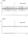
- FIG. 1 shows the signal on the receiving line 24 related to ground (GND) over time after switching on the drive motor of the vacuum pump 11.
- this signal has interference with such an amplitude that a clear evaluation of the voltage signal on line 24 is no longer possible. Specifically, the interference does not allow the voltage sensed on the receiving line 24 to be assigned to one of the six different voltage ranges within the interval from 0.38V to 2.74V. Consequently, at the in Figure 2A In the case shown, the type of accessory device 15 cannot be recognized from the signal present on the receiving line 24 and from the corresponding characteristic resistor 19 .
- the vacuum pump 11 has an interference suppression device in the form of a low-pass filter 31 (cf. 1 ), which comprises a resistor 33 connected in series and a capacitor 35 connected in parallel with respect to the receiving line 24 .
- the vacuum pump 11 has a switching device 37 which includes a transistor 39 and a control line 41 which in turn is connected to the microcontroller 17 .
- the capacitor As soon as the transistor 39 is turned on by means of the control line 41, the capacitor is connected to ground (GND), so that the low-pass filter 31 is activated as an interference suppression device. If, on the other hand, the transistor 39 is blocked or switched off by means of the control line 41, the capacitor 35 and thus also the low-pass filter 31 as an interference suppression device are deactivated.
- FIG 2B is the signal on the receiving line 24 as a voltage signal 27 behind the low-pass filter 31 (cf. 1 ) shown after its activation, as measured by the microcontroller 17.
- the fluctuations or disturbances in the analog voltage signal 27 are considerably smaller after the activation of the low-pass filter 31 (cf. Figure 2B ) than without activating the low-pass filter 31 (cf. Figure 2A ).
- the microcontroller 17 and the interface 13 of the vacuum pump 11 are also provided for identifying those accessory devices 15 that send digital data packets, which are also recorded via the receiving line 24 by the microcontroller 17 .
- the microcontroller 17 sends a signal to the accessory device 15 via the transmission line 23 in order to thereby trigger the transmission of the digital data packets via the reception line 24 .
- the detection of the digital data packets on the receiving line 24 allows the corresponding accessory device 15 to be uniquely identified by means of the controller 17.
- the low-pass filter 31 is activated as an interference suppression device by switching the switching device 37 on, ie if the transistor 39 is switched on by means of the control line 41, the digital signals on the receiving line 24 are short-circuited, as is shown in FIG Figure 3B is shown.
- digital signals are plotted over time, ie the voltage signal 27 behind the low-pass filter 31 over time in the event that a "digital" accessory device 15 such as a pressure gauge is connected to the vacuum pump 11 via the interface 13 .
- the accessory device 15 cannot be identified using the digital data packets that are detected via the receiving line 24.
- the low-pass filter 31 is deactivated if digital data packets are to be recorded via the receiving line 24.
- the microcontroller 17 determines whether a characteristic resistor 19 in of the accessory device 15 is present. To determine this, the microcontroller 17 checks whether there is a measurable voltage between the receiving line 24 and ground (GND) or whether the receiving line 24 is open to ground. If a voltage can be measured between the receiving line 24 and ground, the accessory device 15 has the characteristic resistor 19 so that a static, analog signal on the receiving line 24 can be detected. In this case, the microcontroller 17 activates the low-pass filter 31 via the control line 41 by the transistor 39 being switched on. This means that the static analog signal is suppressed by means of the low-pass filter 31, as is shown in Figure 2B is shown.
- GND receiving line 24 and ground
- the receiving line 24 is open to ground and the microcontroller 17 cannot determine a voltage corresponding to a particular characteristic resistor 19 in this case. Consequently, in this case, digital data packets are to be detected on the receiving line 24, so that the microcontroller 17 deactivates the low-pass filter 31 via the control line 41 by switching the transistor 39 to “non-conducting”. As a result, the low-pass filter 31 does not affect the digital data packets, which can therefore be recorded without hindrance, as is shown in Figure 3A is shown.
- the microcontroller 17 uses the signal on the receiving line 24 to determine whether the accessory device 15 has a characteristic resistor 19 or not, and activates or deactivates the low-pass filter 31 accordingly in order to either transmit an undisturbed analog signal (cf. Figure 2B ) or an undisturbed digital data package (cf. Figure 3A ) to be able to capture.
- the selective activation or deactivation of the low-pass filter 31 thus enables correct automatic accessory detection both by means of analog signals (cf. Figure 2B ) by detecting the characteristic resistance 19 as well as by means of digital data packets (cf. Figure 3A ) possible even if the drive motor of the vacuum pump 11 is controlled by means of the pulse width modulated signal.
- the limit frequency of the low-pass filter 31 can be set in such a way that the possible interference in the analog signal (cf. Figure 2A ) can be suitably suppressed.
- a resistor with 820 ⁇ and a capacitor with 220 nF were chosen, resulting in a cut-off frequency of 882 Hz for the low-pass filter 31. It has been shown that a limit frequency of 1 kHz of the low-pass filter 31 is sufficient to suppress the interference that can be caused by the pulse-width-modulated signals for the drive motor of a turbomolecular pump.
Landscapes
- Engineering & Computer Science (AREA)
- Mechanical Engineering (AREA)
- General Engineering & Computer Science (AREA)
- Non-Positive Displacement Air Blowers (AREA)
- Connection Of Motors, Electrical Generators, Mechanical Devices, And The Like (AREA)
- Compressors, Vaccum Pumps And Other Relevant Systems (AREA)
- Control Of Positive-Displacement Pumps (AREA)
Abstract
Description
- Die Erfindung betrifft eine Vakuumpumpe, bei der sich insbesondere um eine Turbomolekularpumpe handelt und die mit einer Schnittstelle ausgestattet ist, um die Vakuumpumpe mit einer Zubehöreinrichtung zu verbinden.
- Viele Vakuumpumpen können mit Zubehöreinrichtungen elektrisch verbunden werden, um beispielsweise Daten zu erfassen, die zur Steuerung der Vakuumpumpe oder einer Vakuumanlage verwendet werden, in der sich die Vakuumpumpe befindet, oder um die Vakuumpumpe zusammen mit der Zubehöreinrichtung zu steuern. Beispiele für solche Zubehöreinrichtungen sind Druckmesseinrichtungen, Flutventile und Lüfter.
- Ferner sind viele Vakuumpumpen in der Lage, beim Anschließen einer Zubehöreinrichtung eine automatische Zubehörerkennung durchzuführen, bei welcher ein Controller der Vakuumpumpe automatisch ermittelt, welcher Typ der Zubehöreinrichtungen momentan an eine Schnittstelle der Vakuumpumpe angeschlossen ist. Nach der automatischen Zubehörerkennung können beispielsweise korrekte Kennlinien zur Steuerung der Zubehöreinrichtung ausgewählt werden.
- Die automatische Zubehörerkennung kann mittels analoger Signale und Kennwiderständen erfolgen, die in der Zubehöreinrichtung vorhanden sind und über die Schnittstelle der Vakuumpumpe ausgelesen werden. Alternativ kann die Zubehörerkennung mittels digitaler Signale erfolgen, die über die Schnittstelle von der Vakuumpumpe angefordert werden und von der Zubehöreinrichtung in der Form von digitalen Datenpaketen an den Controller der Vakuumpumpe gesendet werden.
- Bei der Verbindung der Vakuumpumpe mit der Zubehöreinrichtung ist es wünschenswert, als Schnittstelle eine standardisierte Steckverbindung zu verwenden, beispielsweise eine Mikro-USB-Steckverbindung, um dadurch die Herstellungskosten zu verringern und die Flexibilität bezüglich der anschließbaren Zubehöreinrichtungen zu erhöhen. Es ist jedoch ebenso wünschenswert, auch dann eine automatische Zubehörerkennung durchführen zu können, wenn dieselbe Schnittstelle für alle Typen der Zubehöreinrichtungen verwendet wird, d.h. unabhängig davon, ob die Zubehöreinrichtung einen Kennwiderstand aufweist oder als "intelligentes" Zubehör digitale Datenpakete senden kann.
- Aufgrund der begrenzten Anzahl von Anschlusspolen bzw. Datenleitungen in standardisierten Schnittstellen bzw. Steckverbindungen ist es jedoch häufig erforderlich, eine gemeinsame Leitung für die Zubehörerkennung zu verwenden, d.h. sowohl für die analoge Zubehörerkennung mittels Kennwiderständen als auch für die Zubehörerkennung mit digitalen Datenpaketen. Im Betrieb der Vakuumpumpe, d.h. bei eingeschaltetem Antriebsmotor, können allerdings Störungen auftreten, beispielsweise durch eine Endstufen-Pulsweitenmodulation bei Turbomolekularpumpen zur Ansteuerung des Antriebsmotors. Dies kann bei einer Zubehörerkennung mittels Analogsignal dazu führen, dass eine automatische Zubehörerkennung aufgrund der Störungen nicht mehr möglich ist. Die Störungen können zwar mittels eines geeigneten, fest verbundenen Kondensators im Bereich der Schnittstelle der Vakuumpumpe verringert werden. Ein solcher fest installierter Kondensator bewirkt jedoch, dass digitale Signale an der Schnittstelle der Vakuumpumpe kurzgeschlossen werden und eine automatische Zubehörerkennung mittels der digitalen Datenpakete verhindert wird.
- Eine Aufgabe der Erfindung besteht darin, eine Vakuumpumpe zu schaffen, bei der eine automatische Zubehörerkennung im Betrieb der Vakuumpumpe auch dann zuverlässig durchführbar ist, wenn unterschiedliche Typen von Signalen, insbesondere analoge oder digitale Signale, an einer Schnittstelle der Vakuumpumpe verfügbar sind.
- Diese Aufgabe wird durch eine Vakuumpumpe mit den Merkmalen des Anspruchs 1 gelöst.
- Die Vakuumpumpe, bei der es sich insbesondere um eine Turbomolekularpumpe handelt, weist eine Schnittstelle zum Verbinden der Vakuumpumpe mit einer Zubehöreinrichtung, einen Controller, der mit der Schnittstelle in Verbindung steht, und eine Entstörungseinrichtung auf, die mit der Schnittstelle und dem Controller verbunden ist. Der Controller ist ausgebildet, um zumindest zwei unterschiedliche Typen eines Signals zu erkennen, das an der Schnittstelle der Vakuumpumpe anliegt, und um die Entstörungseinrichtung in Abhängigkeit von dem erkannten Typ des an der Schnittstelle anliegenden Signals zu aktivieren.
- Die jeweiligen Verbindungen zwischen der Schnittstelle, dem Controller und der Entstörungseinrichtung können elektrische oder elektronische Verbindungen sein. Ferner kann es sich bei der Schnittstelle um eine standardisierte Schnittstelle handeln, wie beispielsweise eine Mikro-USB-Steckverbindung. Durch die Verwendung einer solchen standardisierten Schnittstelle, beispielsweise mit einer gemeinsamen Datenleitung für analoge und digitale Signale, werden die Herstellungskosten für die Vakuumpumpe im Vergleich zu Vakuumpumpen mit speziell ausgestalteten Schnittstellen verringert.
- Da der Controller zumindest zwei unterschiedliche Signaltypen an der Schnittstelle erkennen kann, lässt sich die Schnittstelle automatisch an diesen Signaltyp anpassen, indem die Entstörungseinrichtung entsprechend dem Signaltyp mittels des Controllers aktiviert oder deaktiviert wird. Beispielsweise kann eine Dämpfung digitaler Datenpakete beim Anschluss von "intelligenten" Zubehöreinrichtungen verhindert werden, während mögliche Störungen bei statischen, analogen Signalen mittels der Entstörungseinrichtung unterdrückt werden können. Aufgrund der Unterdrückung der Störungen ist es ferner beispielsweise bei der Verwendung von Analogsignalen und Kennwiderständen in der Zubehöreinrichtung möglich, eine größere Anzahl von Typen der Zubehöreinrichtung zu unterscheiden.
- Vorteilhafte Weiterbildungen der Erfindung sind in den Unteransprüchen, der Beschreibung und den Zeichnungen angegeben.
- Gemäß einer Ausführungsform kann die Vakuumpumpe ferner eine Schalteinrichtung aufweisen, die mit der Entstörungseinrichtung und dem Controller verbunden ist. In diesem Fall kann der Controller ausgebildet sein, um die Entstörungseinrichtung mittels der Schalteinrichtung selektiv zu aktivieren. Die Entstörungseinrichtung kann somit über die Schalteinrichtung zuverlässig aktiviert oder deaktiviert werden.
- Die Schalteinrichtung kann ferner einen Transistor umfassen. Es hat sich gezeigt, dass ein handelsüblicher Transistor als Schalteinrichtung besonders geeignet sein kann, da ein solcher innerhalb der Vakuumpumpe wenig Bauraum in Anspruch nimmt. Alternativ kann die Schalteinrichtung jedoch auch als Schalter oder Optokoppler ausgebildet sein.
- Der Controller kann ferner ausgebildet sein, um anhand des an der Schnittstelle anliegenden Signals zu erkennen, ob die Zubehöreinrichtung einen Kennwiderstand aufweist. Falls das Vorhandensein eines Kennwiderstands erkannt wird, kann ein analoger Signaltyp an der Schnittstelle anliegen. Wenn umgekehrt erkannt wird, dass die Zubehöreinrichtung keinen Kennwiderstand aufweist, kann ein digitaler Signaltyp an der Schnittstelle anliegen. Somit kann der Controller bei dieser Ausführungsform anhand des Vorhandenseins des Kennwiderstands erkennen, welcher Signaltyp an der Schnittstelle anliegt, und die Entstörungseinrichtung entsprechend aktivieren oder deaktivieren. Konkret kann der Controller die Entstörungseinrichtung aktivieren, wenn die Zubehöreinrichtung den Kennwiderstand aufweist, und die Entstörungseinrichtung deaktivieren, wenn die Zubehöreinrichtung keinen Kennwiderstand aufweist. Das Vorhandensein des Kennwiderstands kann somit eine eindeutige und zuverlässige Bedingung für die Aktivierung der Entstörungseinrichtung darstellen.
- Darüber hinaus kann der Controller den Kennwiderstand der Zubehöreinrichtung anhand einer Spannung identifizieren, die zwischen zwei Eingangsleitungen der Schnittstelle anliegt. Beispielsweise kann eine Spannung in einem vorgegebenen Bereich einem bestimmten Typ der Zubehöreinrichtungen zugeordnet sein. Der Controller ist bei dieser Ausführungsform folglich nicht nur in der Lage, mindestens zwei unterschiedliche Signaltypen, sondern auch unterschiedliche Typen von Zubehöreinrichtungen zu unterscheiden, die den gleichen Signaltyp an der Schnittstelle bereitstellen. Wenn an den zwei Eingangsleitungen der Schnittstelle jedoch keine Spannung gemessen werden kann, da die zwei Eingangsleitungen beispielsweise offen sind, kann der Controller ermitteln, dass kein Kennwiderstand in der Zubehöreinrichtung vorhanden ist und dass folglich ein digitaler Signaltyp an der Schnittstelle anliegt.
- Gemäß einer weiteren Ausführungsform kann die Entstörungseinrichtung einen Kondensator umfassen. Da an einen solchen Kondensator keine besonderen Anforderungen bestehen, kann die Entstörungseinrichtung folglich kostengünstig realisiert werden. Ferner kann die Entstörungseinrichtung als Tiefpass ausgebildet sein. Zusätzlich zu einem Kondensator kann die Entstörungseinrichtung somit einen Widerstand umfassen, an den wiederum keine besonderen Anforderungen bestehen. Die Größe des Widerstands und des Kondensators legt jedoch die Grenzfrequenz des Tiefpasses fest. Um Störungen zu unterdrücken, die durch einen Antriebsmotor einer Turbomolekularpumpe hervorgerufen werden, kann eine solche Dimensionierung des Widerstands und des Kondensators eines Tiefpasses als Entstörungseinrichtung zweckmäßig sein, dass der Tiefpass eine Grenzfrequenz von ungefähr 1 kHz aufweist.
- Gemäß einer weiteren Ausführungsform umfassen die zumindest zwei unterschiedlichen Typen des an der Schnittstelle anliegenden Signals ein analoges Signal und ein digitales Signal. Wenn der Controller das analoge Signal erkennt, kann die Entstörungseinrichtung aktiviert werden, und wenn der Controller das digitale Signal erkennt, kann die Entstörungseinrichtung deaktiviert werden. Unabhängig davon, ob ein analoges oder digitales Signal an der Schnittstelle anliegt, kann somit eine gemeinsame Datenleitung für diese Signale an der Schnittstelle verwendet bzw. beibehalten werden. Dadurch kann die Verwendung bzw. Beibehaltung einer standardisierten Schnittstelle erfolgen. Die Schnittstelle kann beispielsweise als Mikro-USB-Schnittstelle ausgebildet sein. Eine solche Schnittstelle verfügt beispielsweise über einen 5-poligen Anschluss, bei welchem ein Pol gemeinsam für analoge und digitale Eingangssignale verwendet werden kann.
- Ferner betrifft die Erfindung ein System mit einer Vakuumpumpe, wie sie vorstehend beschrieben ist, und mit einer Zubehöreinrichtung. Die Vakuumpumpe und die Zubehöreinrichtung sind über die Schnittstelle miteinander verbunden, wobei es sich um eine elektrische oder elektronische Verbindung handeln kann. Wie vorstehend erläutert wurde, ist die Vakuumpumpe mittels des Controllers ausgebildet, um zumindest zwei unterschiedliche Typen eines an der Schnittstelle anliegenden Signals, beispielsweise ein analoges Signal oder ein digitales Signal, zu erkennen und die Entstörungseinrichtung entsprechend dem erkannten Typ des an der Schnittstelle anliegenden Signals zu aktivieren.
- Neben der Unterscheidung zumindest zweier unterschiedlicher Signaltypen an der Schnittstelle kann die Vakuumpumpe ferner ausgebildet sein, um einen Typ der Zubehöreinrichtung anhand des an der Schnittstelle anliegenden Signals zu erkennen. Beispielsweise kann der Controller der Vakuumpumpe erkennen, ob die Zubehöreinrichtung einen Kennwiderstand aufweist, und den Typ der Zubehöreinrichtung anhand des Kennwiderstands identifizieren, oder sie kann ein digitales Signal anfordern und anschließend zum Identifizieren der Zubehöreinrichtung auslesen. Die Zubehöreinrichtung kann eine Druckmesseinrichtung umfassen, die beispielsweise ein digitales Signal an der Schnittstelle bereitstellt. Alternativ kann die Zubehöreinrichtung ein Flutventil oder einen Lüfter umfassen, die beispielsweise ein analoges Signal an der Schnittstelle bereitstellen und einen Kennwiderstand aufweisen.
- Die Erfindung betrifft zudem ein Verfahren zum Betreiben einer Vakuumpumpe, insbesondere einer Turbomolekularpumpe, wobei
- eine Schnittstelle der Vakuumpumpe mit einer Zubehöreinrichtung verbunden wird,
- ein Controller mit der Schnittstelle in Verbindung steht,
- eine Entstörungseinrichtung mit der Schnittstelle und dem Controller verbunden ist, wobei
- der Controller zumindest zwei unterschiedliche Typen eines an der Schnittstelle anliegenden Signals erkennt und die Entstörungseinrichtung in Abhängigkeit von dem erkannten Typ des an der Schnittstelle anliegenden Signals selektiv aktiviert.
- Für das erfindungsgemäße Verfahren gelten die zu der erfindungsgemäßen Vakuumpumpe und zu dem erfindungsgemäßen System getroffenen Aussagen entsprechend. Dies gilt insbesondere hinsichtlich Vorteilen und Ausführungsformen.
- Weiterhin versteht sich, dass sämtliche hierin genannten Ausführungsformen miteinander kombiniert werden können, sofern nicht explizit etwas anderes angegeben ist.
- Nachfolgend wird die Erfindung beispielhaft anhand einer vorteilhaften Ausführungsform unter Bezugnahme auf die beigefügten Figuren beschrieben. Es zeigen, jeweils schematisch:
- Fig. 1
- eine erfindungsgemäße Vakuumpumpe, die über eine Schnittstelle mit einer Zubehöreinrichtung verbunden ist,
- Fig. 2A und 2B
- analoge Signale, die an der Schnittstelle gemessen werden, bei deaktivierter bzw. aktivierter Entstörungseinrichtung und
- Fig. 3A und 3B
- digitale Signale, die an der Schnittstelle gemessen werden, bei deaktivierter bzw. aktivierter Entstörungseinrichtung.
-
Fig. 1 zeigt schematisch eine Vakuumpumpe 11, die über eine Schnittstelle 13 mit einer Zubehöreinrichtung 15 verbunden ist, welche zu diesem Zweck einen Stecker 16 aufweist. Die Vakuumpumpe 11 weist ferner einen Mikrocontroller 17 auf, der mit der Schnittstelle 13 in Verbindung steht. Die Vakuumpumpe 11 ist dafür vorgesehen, über die Schnittstelle 13 mit unterschiedlichen Typen der Zubehöreinrichtung 15 verbunden zu werden und den jeweiligen Typ der der Zubehöreinrichtung 15 mittels des Mikrocontrollers 17 automatisch zu erkennen. - Zum Erkennen der Zubehöreinrichtung 15 weisen bestimmte Typen der Zubehöreinrichtung 15 einen Kennwiderstand 19 auf. Solche Zubehöreinrichtungen 15 sind beispielsweise ein Flutventil oder ein Lüfter, die ein analoges Signal für den Mikrocontroller 17 an der Schnittstelle 13 bereitstellen, welches die Größe des Kennwiderstands 19 widerspiegelt. Anhand dieses analogen Signals erkennt der Mikrocontroller 17 die Größe des Kennwiderstands 19 und somit den Typ der Zubehöreinrichtung 15.
- Andere Typen der Zubehöreinrichtung 15, die auch als "intelligente" Zubehöreinrichtung angesehen werden können und mit einer seriellen Schnittstelle ausgestattet sind, senden nach einer entsprechenden Anforderung digitale Datenpakete über die Schnittstelle 13 an den Mikrocontroller 17 der Vakuumpumpe 11. Anhand der digitalen Datenpakete identifiziert der Mikrocontroller 17 den Typ der Zubehöreinrichtung 15. Eine solche Zubehöreinrichtung 15 ist beispielsweise eine Druckmesseinrichtung oder Druckmessröhre.
- Die Schnittstelle 13 ist als Mikro-USB-Steckverbindung ausgebildet und umfasst fünf Pole bzw. Anschlussverbindungen, die mit X4:1 bis X4:5 bezeichnet sind. Der Stecker 16 der Zubehöreinrichtung 15 weist entsprechende Anschlussverbindungen X3:1 bis X3:5 auf, die jedoch je nach Typ der Zubehöreinrichtung 15 unterschiedlich belegt sind bzw. verwendet werden. Die Anschlussverbindungen X4:1 und X4:4 sind für Versorgungsleitungen 21, 22 vorgesehen. Die Versorgungsleitung 21 dient zur Versorgung einer "intelligenten" bzw. "digitalen" Zubehöreinrichtung 15, beispielsweise einer Druckmessröhre, mit einer Spannung von +5V. Die Versorgungsleitung 22 ist hingegen zur Versorgung einer "analogen" Zubehöreinrichtung 15 mit +24V vorgesehen, wie dies etwa bei einem Flutventil oder einem Lüfter notwendig ist.
- Ferner sind an der Schnittstelle 13 die Anschlussverbindungen X4:2 für eine Sendeleitung 23 und X4:3 für eine Empfangsleitung 24 vorgesehen, während die Anschlussverbindung X4:5 über eine Masseleitung 25 mit Masse (GND) verbunden ist. Die Sendeleitung 23 dient dazu, im Falle einer "digitalen" Zubehöreinrichtung 15 eine Anforderung an die Zubehöreinrichtung 15 zu senden, dass die Zubehöreinrichtung 15 digitale Datenpakete zur Zubehörerkennung über die Empfangsleitung 24 an den Mikrocontroller 17 ausgeben soll.
- Da die unterschiedlichen Typen der Zubehöreinrichtung 15 entweder digitale oder analoge Signale zur Zubehörerkennung bereitstellen, müsste die Schnittstelle 13 eigentlich zwei verschiedene Anschlüsse X4:3 für unterschiedliche Empfangsleitungen 24 aufweisen, um sowohl digitale Datenpakete als auch analoge Signale entsprechen dem Kennwiderstand 19 zu erfassen. Mit den Anschlüssen X4:1 und X4:4 für die zwei Versorgungsleitungen 21, 22, dem Anschluss X4:2 für die Sendeleitung 23 und dem Anschluss X4:5 für die Masseleitung 25 müsste die Schnittstelle 13 somit sechs Anschlüsse aufweisen. Da die standardisierte Mikro-USB-Steckverbindung jedoch nur 5-polig ist, ist es notwendig, einen gemeinsamen Anschluss X4:3 und eine gemeinsame Empfangsleitung 24 sowohl für die digitalen als auch für die analogen Signale zu verwenden.
- Die Empfangsleitung 24 dient somit einerseits zum Erfassen einer statischen, analogen Spannung für den Fall, dass die Zubehöreinrichtung 15 einen Kennwiderstand 19 aufweist, wie dies beispielhaft in
Fig. 1 dargestellt ist. Die analoge Spannung über den Kennwiderstand 19, die zwischen der Eingangsleitung 23 und Masse (GND) gemessen wird, wird mittels des Mikrocontrollers 17 der Vakuumpumpe 11 ausgewertet, beispielsweise über einen Spannungsteiler. Die über die Eingangsleitung 24 erfasste analoge Spannung wird typischerweise sechs verschiedenen Werten zwischen 0,38 und 2,74 V zugeordnet, um dadurch den Kennwiderstand 19 und somit den Typ der Zubehöreinrichtung zu identifizieren, beispielsweise ein Flutventil oder einen Lüfter. - Nach dem Einschalten der Vakuumpumpe 11 wird deren Antriebsmotor (nicht gezeigt) mit einem Pulsweiten-modulierten Signal einer Endstufe angesteuert. Wenn die Zubehöreinrichtung 15 den Kennwiderstand 19 aufweist und somit ein analoges Signal an der Empfangsleitung 24 der Schnittstelle 13 anliegt, stört das Pulsweiten-modulierte Signal das Analogsignal an der Empfangsleitung 24 auf eine Weise, wie dies in
Fig. 2A dargestellt ist.Fig. 2A zeigt das Signal an der Empfangsleitung 24 bezogen auf Masse (GND) über der Zeit nach Einschalten des Antriebsmotors der Vakuumpumpe 11. - Man erkennt, dass dieses Signal Störungen mit einer solchen Amplitude aufweist, dass eine eindeutige Auswertung des Spannungssignals an der Leitung 24 nicht mehr möglich ist. Konkret gestatten es die Störungen nicht, die an der Empfangsleitung 24 erfasste Spannung einem der sechs verschiedenen Spannungsbereiche innerhalb des Intervalls von 0,38 V bis 2,74 V zuzuordnen. Folglich kann bei dem in
Fig. 2A dargestellten Fall der Typ der Zubehöreinrichtung 15 nicht anhand des an der Empfangsleitung 24 anliegenden Signals und anhand des entsprechenden Kennwiderstands 19 erkannt werden. - Um die Störungen des Analogsignals an der Empfangsleitung 24 zu beseitigen, weist die Vakuumpumpe 11 eine Entstörungseinrichtung in der Form eines Tiefpasses 31 auf (vgl.
Fig. 1 ), der bezogen auf die Empfangsleitung 24 einen in Reihe geschalteten Widerstand 33 und einen parallel geschalteten Kondensator 35 umfasst. Zusätzlich weist die Vakuumpumpe 11 eine Schalteinrichtung 37 auf, die einen Transistor 39 und eine Steuerleitung 41 umfasst, die wiederum mit dem Mikrocontroller 17 verbunden ist. - Sobald der Transistor 39 mittels der Steuerleitung 41 leitend geschaltet ist, ist der Kondensator mit Masse (GND) verbunden, so dass der Tiefpass 31 als Entstörungseinrichtung aktiviert ist. Wenn der Transistor 39 hingegen gesperrt ist bzw. mittels der Steuerleitung 41 nichtleitend geschaltet ist, ist der Kondensator 35 und damit auch der Tiefpass 31 als Entstörungseinrichtung deaktiviert.
- In
Fig. 2B ist das Signal an der Empfangsleitung 24 als Spannungssignal 27 hinter dem Tiefpass 31 (vgl.Fig. 1 ) nach dessen Aktivierung dargestellt, wie es mittels des Mikrocontrollers 17 gemessen wird. Die Schwankungen bzw. Störungen des analogen Spannungssignals 27 sind nach Aktivierung des Tiefpasses 31 erheblich kleiner (vgl.Fig. 2B ) als ohne Aktivierung des Tiefpasses 31 (vgl.Fig. 2A ). - Wie bereits erwähnt wurde, sind der Mikrocontroller 17 und die Schnittstelle 13 der Vakuumpumpe 11 auch zum Identifizieren solcher Zubehöreinrichtungen 15 vorgesehen, die digitale Datenpakete senden, welche ebenfalls über die Empfangsleitung 24 mittels des Mikrocontrollers 17 erfasst werden. Über die Sendeleitung 23 sendet der Mikrocontroller 17 ein Signal an die Zubehöreinrichtung 15, um dadurch das Senden der digitalen Datenpakete über die Empfangsleitung 24 auszulösen. Das Erfassen der digitalen Datenpakete an der Empfangsleitung 24 gestattet eine eindeutige Identifikation der entsprechenden Zubehöreinrichtung 15 mittels des Controllers 17.
- Wenn der Tiefpass 31 jedoch als Entstörungseinrichtung aktiviert ist, indem die Schalteinrichtung 37 eingeschaltet ist, d.h. wenn der Transistor 39 mittels der Steuerleitung 41 leitend geschaltet ist, werden die digitalen Signale an der Empfangsleitung 24 kurzgeschlossen, wie dies in
Fig. 3B dargestellt ist. InFig. 3A und 3B sind jeweils digitale Signale über der Zeit aufgetragen, d.h. das Spannungssignal 27 hinter dem Tiefpass 31 über der Zeit für den Fall, dass eine "digitale" Zubehöreinrichtung 15 wie beispielsweise eine Druckmessröhre über die Schnittstelle 13 mit der Vakuumpumpe 11 verbunden ist. - Da die digitalen Signale über den Kondensator 35 des Tiefpasses 31 kurzgeschlossen werden, wenn der Tiefpass 31 über den leitenden Transistor 39 aktiviert ist, ist keine Erkennung der Zubehöreinrichtung 15 anhand der digitalen Datenpakete möglich, die über die Empfangsleitung 24 erfasst werden. Um dies zu verhindern, wird der Tiefpass 31 deaktiviert, wenn digitale Datenpakete über die Empfangsleitung 24 erfasst werden sollen.
- Dies erfolgt dadurch, dass der Transistor 39 mittels der Steuerleitung 41 gesperrt bzw. auf "nichtleitend" umgeschaltet wird. Dadurch wird der Kondensator 35 und somit der Tiefpass 31 deaktiviert, so dass die digitalen Datenpakete wie gewünscht durch den Mikrocontroller 17 erfasst werden können. Dies ist in
Fig. 3A dargestellt, in welcher die digitalen Signale über der Zeit aufgetragen sind, während der Tiefpass 31 mittels des Transistors 39 über die Steuerleitung 41 deaktiviert ist. InFig. 3A ist ebenfalls zu erkennen, dass die digitalen Signale nicht durch das Pulsweiten-modulierte Signal beeinträchtigt werden, mit dem der Antriebsmotor der Vakuumpumpe 11 angesteuert wird. - Um festzustellen, ob eine "analoge" oder "digitale" Zubehöreinrichtung 15 an der Schnittstelle 13 angeschlossen ist und ob entsprechend ein statisches, analoges Signal oder ein digitales Datenpaket über die Empfangsleitung 24 zu erfassen ist, ermittelt der Mikrocontroller 17, ob ein Kennwiderstand 19 in der Zubehöreinrichtung 15 vorhanden ist. Um dies festzustellen, überprüft der Mikrocontroller 17, ob zwischen der Empfangsleitung 24 und Masse (GND) eine messbare Spannung anliegt oder ob die Empfangsleitung 24 gegenüber Masse offen ist. Wenn eine Spannung zwischen der Empfangsleitung 24 und Masse messbar ist, weist die Zubehöreinrichtung 15 den Kennwiderstand 19 auf, so dass ein statisches, analoges Signal an der Empfangsleitung 24 zu erfassen ist. In diesem Fall aktiviert der Mikrocontroller 17 den Tiefpass 31 über die Steuerleitung 41, indem der Transistor 39 leitend geschaltet wird. Dies führt dazu, dass das statische Analogsignal mittels des Tiefpasses 31 entstört wird, wie dies in
Fig. 2B dargestellt ist. - Wenn die Zubehöreinrichtung 15 jedoch keinen Kennwiderstand 19 aufweist, ist die Empfangsleitung 24 gegenüber Masse offen, und der Mikrocontroller 17 kann in diesem Fall keine Spannung ermitteln, die einem bestimmten Kennwiderstand 19 entspricht. Folglich sind in diesem Fall digitale Datenpakete an der Empfangsleitung 24 zu erfassen, so dass der Mikrocontroller 17 den Tiefpass 31 über die Steuerleitung 41 deaktiviert, indem der Transistor 39 auf "nichtleitend" umgeschaltet wird. Dadurch beeinträchtigt der Tiefpass 31 die digitalen Datenpakete nicht, die somit ungehindert erfasst werden können, wie dies in
Fig. 3A dargestellt ist. - Insgesamt ermittelt der Mikrocontroller 17 somit anhand des Signals an der Empfangsleitung 24, ob die Zubehöreinrichtung 15 einen Kennwiderstand 19 aufweist oder nicht, und aktiviert oder deaktiviert den Tiefpass 31 entsprechend, um entweder ein ungestörtes Analogsignal (vgl.
Fig. 2B ) oder ein ungestörtes digitales Datenpaket (vgl.Fig. 3A ) erfassen zu können. Durch die selektive Aktivierung oder Deaktivierung des Tiefpasses 31 ist somit eine korrekte automatische Zubehörerkennung sowohl mittels analoger Signale (vgl.Fig. 2B ) durch Erfassen des Kennwiderstands 19 als auch mittels digitaler Datenpakete (vgl.Fig. 3A ) möglich, selbst wenn der Antriebsmotor der Vakuumpumpe 11 mittels des Pulsweiten-modulierten Signals angesteuert wird. - Durch geeignete Dimensionierung des Widerstands 33 und des Kondensators 35 lässt sich die Grenzfrequenz des Tiefpasses 31 derart festlegen, dass die möglichen Störungen des analogen Signals (vgl.
Fig. 2A ) geeignet unterdrückt werden können. Im vorliegenden Beispiel wurde ein Widerstand mit 820 Ω und ein Kondensator mit 220 nF gewählt, so dass sich eine Grenzfrequenz von 882 Hz für den Tiefpass 31 ergibt. Es hat sich gezeigt, dass zum Unterdrücken der Störungen, die durch die Pulsweiten-modulierten Signale für den Antriebsmotor einer Turbomolekularpumpe hervorgerufen werden können, eine Grenzfrequenz von 1 kHz des Tiefpasses 31 ausreichend ist. -
- 11
- Vakuumpumpe
- 13
- Schnittstelle der Vakuumpumpe
- 15
- Zubehöreinrichtung
- 16
- Stecker der Zubehöreinrichtung
- 17
- Mikrocontroller
- 19
- Kennwiderstand
- 21
- +5V-Versorgungsleitung
- 22
- +24V-Versorgungsleitung
- 23
- Sendeleitung
- 24
- Empfangsleitung
- 25
- Masseleitung
- 27
- Spannungssignal nach Tiefpass
- 31
- Tiefpass
- 33
- Widerstand
- 35
- Kondensator
- 37
- Schalteinrichtung
- 39
- Transistor
- 41
- Steuerleitung
- X4:1 bis X4:5
- Anschlüsse an der Schnittstelle der Vakuumpumpe
- X3:1 bis X3:5
- Anschlüsse am Stecker der Zubehöreinrichtung
Claims (15)
- Vakuumpumpe (11), insbesondere Turbomolekularpumpe, miteiner Schnittstelle (13) zum Verbinden der Vakuumpumpe (11) mit einer Zubehöreinrichtung (15),einem Controller (17), der mit der Schnittstelle (13) in Verbindung steht,einer Entstörungseinrichtung (31), die mit der Schnittstelle (13) und dem Controller (17) verbunden ist,wobei der Controller (17) ausgebildet ist, um:zumindest zwei unterschiedliche Typen eines an der Schnittstelle (13) anliegenden Signals zu erkennen unddie Entstörungseinrichtung (31) in Abhängigkeit von dem erkannten Typ des an der Schnittstelle (13) anliegenden Signals selektiv zu aktivieren.
- Vakuumpumpe (11) nach Anspruch 1,die ferner eine Schalteinrichtung (37) aufweist, die mit der Entstörungseinrichtung (31) und dem Controller (17) verbunden ist,wobei der Controller (17) ausgebildet ist, um die Entstörungseinrichtung (31) mittels der Schalteinrichtung (37) selektiv zu aktivieren.
- Vakuumpumpe (11) nach Anspruch 2,
wobei die Schalteinrichtung (37) einen Transistor (39) umfasst. - Vakuumpumpe (11) nach einem der Ansprüche 1 bis 3,
wobei der Controller (17) ausgebildet ist, um anhand des an der Schnittstelle (13) anliegenden Signals zu erkennen, ob die Zubehöreinrichtung (15) einen Kennwiderstand (19) aufweist. - Vakuumpumpe (11) nach Anspruch 4,
wobei der Controller (17) die Entstörungseinrichtung (31) aktiviert, wenn die Zubehöreinrichtung (15) den Kennwiderstand (19) aufweist, und die Entstörungseinrichtung (31) deaktiviert, wenn die Zubehöreinrichtung (15) keinen Kennwiderstand (19) aufweist. - Vakuumpumpe (11) nach Anspruch 4 oder 5,
wobei der Controller (17) den Kennwiderstand (19) der Zubehöreinrichtung (15) anhand einer Spannung (27) identifiziert, die zwischen zwei Eingangsleitungen (24, 25) der Schnittstelle (13) anliegt. - Vakuumpumpe (11) nach einem der Ansprüche 1 bis 6,
wobei die Entstörungseinrichtung (31) einen Kondensator (35) umfasst. - Vakuumpumpe (11) nach einem der Ansprüche 1 bis 7,
wobei die Entstörungseinrichtung (31) als Tiefpass ausgebildet ist. - Vakuumpumpe (11) nach einem der Ansprüche 1 bis 8,
wobei die zumindest zwei unterschiedlichen Typen des an der Schnittstelle (13) anliegenden Signals ein analoges Signal und ein digitales Signal umfassen. - Vakuumpumpe (11) nach Anspruch 9,wobei die Entstörungseinrichtung (31) aktiviert ist, wenn der Controller (17) das analoge Signal erkennt, undwobei die Entstörungseinrichtung (31) deaktiviert ist, wenn der Controller (17) das digitale Signal erkennt.
- Vakuumpumpe (11) nach einem der Ansprüche 1 bis 10,
wobei die Schnittstelle (13) als Mikro-USB-Schnittstelle ausgebildet ist. - System mit einer Vakuumpumpe (11) nach einem der Ansprüche 1 bis 11 und einer Zubehöreinrichtung (15),
wobei die Vakuumpumpe (11) und die Zubehöreinrichtung (15) über die Schnittstelle (13) miteinander verbunden sind. - System nach Anspruch 12,
wobei die Vakuumpumpe (11) ausgebildet ist, um einen Typ der Zubehöreinrichtung (15) anhand des an der Schnittstelle (13) anliegenden Signals zu erkennen. - System nach Anspruch 12 oder 13,
wobei die Zubehöreinrichtung (15) eine Druckmesseinrichtung, ein Flutventil oder einen Lüfter umfasst. - Verfahren zum Betreiben einer Vakuumpumpe (11), insbesondere einer Turbomolekularpumpe, wobeieine Schnittstelle (13) der Vakuumpumpe (11) mit einer Zubehöreinrichtung (15) verbunden wird,ein Controller (17) mit der Schnittstelle (13) in Verbindung steht, eine Entstörungseinrichtung (31) mit der Schnittstelle (13) und dem Controller (17) verbunden ist,wobei der Controller (17) zumindest zwei unterschiedliche Typen eines an der Schnittstelle (13) anliegenden Signals erkennt und
die Entstörungseinrichtung (31) in Abhängigkeit von dem erkannten Typ des an der Schnittstelle (13) anliegenden Signals selektiv aktiviert.
Priority Applications (2)
| Application Number | Priority Date | Filing Date | Title |
|---|---|---|---|
| EP21213446.4A EP4006350B1 (de) | 2021-12-09 | 2021-12-09 | Vakuumpumpe |
| JP2022103401A JP7515540B2 (ja) | 2021-12-09 | 2022-06-28 | 真空ポンプ |
Applications Claiming Priority (1)
| Application Number | Priority Date | Filing Date | Title |
|---|---|---|---|
| EP21213446.4A EP4006350B1 (de) | 2021-12-09 | 2021-12-09 | Vakuumpumpe |
Publications (2)
| Publication Number | Publication Date |
|---|---|
| EP4006350A1 true EP4006350A1 (de) | 2022-06-01 |
| EP4006350B1 EP4006350B1 (de) | 2023-09-13 |
Family
ID=78827985
Family Applications (1)
| Application Number | Title | Priority Date | Filing Date |
|---|---|---|---|
| EP21213446.4A Active EP4006350B1 (de) | 2021-12-09 | 2021-12-09 | Vakuumpumpe |
Country Status (2)
| Country | Link |
|---|---|
| EP (1) | EP4006350B1 (de) |
| JP (1) | JP7515540B2 (de) |
Citations (3)
| Publication number | Priority date | Publication date | Assignee | Title |
|---|---|---|---|---|
| US8467890B2 (en) * | 2008-11-10 | 2013-06-18 | Broadcom Corporation | Method and system for detecting interrupts from detachable electronic accessories or peripherals |
| GB2502983A (en) * | 2012-06-12 | 2013-12-18 | Incus Lab Ltd | Electronic host device with flexible interface for accessory connection |
| EP3647600A1 (de) * | 2019-10-08 | 2020-05-06 | Pfeiffer Vacuum Gmbh | Erkennung eines elektrisch angeschlossenen zubehörs |
-
2021
- 2021-12-09 EP EP21213446.4A patent/EP4006350B1/de active Active
-
2022
- 2022-06-28 JP JP2022103401A patent/JP7515540B2/ja active Active
Patent Citations (3)
| Publication number | Priority date | Publication date | Assignee | Title |
|---|---|---|---|---|
| US8467890B2 (en) * | 2008-11-10 | 2013-06-18 | Broadcom Corporation | Method and system for detecting interrupts from detachable electronic accessories or peripherals |
| GB2502983A (en) * | 2012-06-12 | 2013-12-18 | Incus Lab Ltd | Electronic host device with flexible interface for accessory connection |
| EP3647600A1 (de) * | 2019-10-08 | 2020-05-06 | Pfeiffer Vacuum Gmbh | Erkennung eines elektrisch angeschlossenen zubehörs |
Also Published As
| Publication number | Publication date |
|---|---|
| JP2023086079A (ja) | 2023-06-21 |
| JP7515540B2 (ja) | 2024-07-12 |
| EP4006350B1 (de) | 2023-09-13 |
Similar Documents
| Publication | Publication Date | Title |
|---|---|---|
| EP1490772B1 (de) | Verfahren zum adressieren der teilnehmer eines bussystems mittels identifizierungsströmen | |
| DE69418982T2 (de) | Verfahren und Vorrichtung zum Überwachen und Auswerten von Sensorsignalen | |
| AT510379B1 (de) | Diagnosetool zum anschluss an eine fahrzeug-diagnosebuchse | |
| EP1217528B1 (de) | Schaltungsanordnung zur Fehlerkennung eines Zweidraht-Datenbusses | |
| DE102010009775A1 (de) | Schaltschranküberwachungseinrichtung | |
| EP1039357A2 (de) | Einrichtung zum Einstellen von Betriebsgrössen in mehreren programmierbaren integrierten Schaltungen | |
| EP0415039A2 (de) | Elektronische Schaltung zur Überwachung eines Endverstärkers und seiner Last | |
| DE19839073C2 (de) | Verfahren und Vorrichtung zur Diagnose einer Zündanlage für eine Brennkraftmaschine | |
| EP4006350B1 (de) | Vakuumpumpe | |
| WO2017076572A1 (de) | Bussystem und verfahren zur diagnose eines kurzschlusses | |
| EP3818628B1 (de) | Verfahren und vorrichtung zum betreiben eines elektromotors für eine elektrische bremseinrichtung | |
| EP3830589A1 (de) | Kontaktüberwachungseinrichtung für eine sicherheitskritische auslösevorrichtung eines schaltgeräts | |
| DE10163393B4 (de) | Anschlusselement für einen Bus | |
| WO2005027549A1 (de) | Verlängerung der sim-karten-schnittstelle in gsm-geräten | |
| DE3642500A1 (de) | System zur ein- und/oder ausgabe von signalen eines digitalen steuersystems | |
| DE10061025B4 (de) | Mehrstellungs-Schalter-Anordnung in Kraftfahrzeugen | |
| EP1160580A1 (de) | Schaltungsanordnung zur Detektion einer Funktionsstörung | |
| DE102018201520B4 (de) | Sensoreinrichtung zum Erfassen eines elektrisch leitfähigen Mediums und Verfahren zum Betreiben einer Sensoreinrichtung | |
| EP0927356B1 (de) | Verfahren zur prüfung elektrischer bauteile und vorrichtung zur durchführung des verfahrens | |
| EP4038843B1 (de) | Bussystem und verfahren zum betreiben eines bussystems | |
| DE10246107B4 (de) | Verfahren sowie Schaltungsanordnung zur Fehlerüberwachung wenigstens eines elektrischen Verbrauchers | |
| DE10111468B4 (de) | Verfahren und Vorrichtung zur Ermittlung von Eigenschaften gesteckter Module | |
| EP3139223A1 (de) | Sensoreinrichtung zur überwachung eines sensorbereichs und verfahren zum umschalten zwischen zwei betriebsmodi | |
| DE4422173A1 (de) | Schaltungsanordnung zur Umschaltung eines sich in einem Steuersystem befindenden Mikroprozessors in einen programmfreien Betriebsmodus, insbesondere für Kraftfahrzeuge | |
| DE10018051B4 (de) | Näherungssensor |
Legal Events
| Date | Code | Title | Description |
|---|---|---|---|
| PUAI | Public reference made under article 153(3) epc to a published international application that has entered the european phase |
Free format text: ORIGINAL CODE: 0009012 |
|
| STAA | Information on the status of an ep patent application or granted ep patent |
Free format text: STATUS: THE APPLICATION HAS BEEN PUBLISHED |
|
| AK | Designated contracting states |
Kind code of ref document: A1 Designated state(s): AL AT BE BG CH CY CZ DE DK EE ES FI FR GB GR HR HU IE IS IT LI LT LU LV MC MK MT NL NO PL PT RO RS SE SI SK SM TR |
|
| STAA | Information on the status of an ep patent application or granted ep patent |
Free format text: STATUS: REQUEST FOR EXAMINATION WAS MADE |
|
| 17P | Request for examination filed |
Effective date: 20220531 |
|
| RBV | Designated contracting states (corrected) |
Designated state(s): AL AT BE BG CH CY CZ DE DK EE ES FI FR GB GR HR HU IE IS IT LI LT LU LV MC MK MT NL NO PL PT RO RS SE SI SK SM TR |
|
| GRAP | Despatch of communication of intention to grant a patent |
Free format text: ORIGINAL CODE: EPIDOSNIGR1 |
|
| STAA | Information on the status of an ep patent application or granted ep patent |
Free format text: STATUS: GRANT OF PATENT IS INTENDED |
|
| INTG | Intention to grant announced |
Effective date: 20230623 |
|
| GRAS | Grant fee paid |
Free format text: ORIGINAL CODE: EPIDOSNIGR3 |
|
| GRAA | (expected) grant |
Free format text: ORIGINAL CODE: 0009210 |
|
| STAA | Information on the status of an ep patent application or granted ep patent |
Free format text: STATUS: THE PATENT HAS BEEN GRANTED |
|
| AK | Designated contracting states |
Kind code of ref document: B1 Designated state(s): AL AT BE BG CH CY CZ DE DK EE ES FI FR GB GR HR HU IE IS IT LI LT LU LV MC MK MT NL NO PL PT RO RS SE SI SK SM TR |
|
| REG | Reference to a national code |
Ref country code: CH Ref legal event code: EP |
|
| REG | Reference to a national code |
Ref country code: DE Ref legal event code: R096 Ref document number: 502021001476 Country of ref document: DE |
|
| REG | Reference to a national code |
Ref country code: IE Ref legal event code: FG4D Free format text: LANGUAGE OF EP DOCUMENT: GERMAN |
|
| REG | Reference to a national code |
Ref country code: LT Ref legal event code: MG9D |
|
| REG | Reference to a national code |
Ref country code: NL Ref legal event code: MP Effective date: 20230913 |
|
| PG25 | Lapsed in a contracting state [announced via postgrant information from national office to epo] |
Ref country code: GR Free format text: LAPSE BECAUSE OF FAILURE TO SUBMIT A TRANSLATION OF THE DESCRIPTION OR TO PAY THE FEE WITHIN THE PRESCRIBED TIME-LIMIT Effective date: 20231214 |
|
| PG25 | Lapsed in a contracting state [announced via postgrant information from national office to epo] |
Ref country code: SE Free format text: LAPSE BECAUSE OF FAILURE TO SUBMIT A TRANSLATION OF THE DESCRIPTION OR TO PAY THE FEE WITHIN THE PRESCRIBED TIME-LIMIT Effective date: 20230913 Ref country code: RS Free format text: LAPSE BECAUSE OF FAILURE TO SUBMIT A TRANSLATION OF THE DESCRIPTION OR TO PAY THE FEE WITHIN THE PRESCRIBED TIME-LIMIT Effective date: 20230913 Ref country code: NO Free format text: LAPSE BECAUSE OF FAILURE TO SUBMIT A TRANSLATION OF THE DESCRIPTION OR TO PAY THE FEE WITHIN THE PRESCRIBED TIME-LIMIT Effective date: 20231213 Ref country code: LV Free format text: LAPSE BECAUSE OF FAILURE TO SUBMIT A TRANSLATION OF THE DESCRIPTION OR TO PAY THE FEE WITHIN THE PRESCRIBED TIME-LIMIT Effective date: 20230913 Ref country code: LT Free format text: LAPSE BECAUSE OF FAILURE TO SUBMIT A TRANSLATION OF THE DESCRIPTION OR TO PAY THE FEE WITHIN THE PRESCRIBED TIME-LIMIT Effective date: 20230913 Ref country code: HR Free format text: LAPSE BECAUSE OF FAILURE TO SUBMIT A TRANSLATION OF THE DESCRIPTION OR TO PAY THE FEE WITHIN THE PRESCRIBED TIME-LIMIT Effective date: 20230913 Ref country code: GR Free format text: LAPSE BECAUSE OF FAILURE TO SUBMIT A TRANSLATION OF THE DESCRIPTION OR TO PAY THE FEE WITHIN THE PRESCRIBED TIME-LIMIT Effective date: 20231214 Ref country code: FI Free format text: LAPSE BECAUSE OF FAILURE TO SUBMIT A TRANSLATION OF THE DESCRIPTION OR TO PAY THE FEE WITHIN THE PRESCRIBED TIME-LIMIT Effective date: 20230913 |
|
| PG25 | Lapsed in a contracting state [announced via postgrant information from national office to epo] |
Ref country code: NL Free format text: LAPSE BECAUSE OF FAILURE TO SUBMIT A TRANSLATION OF THE DESCRIPTION OR TO PAY THE FEE WITHIN THE PRESCRIBED TIME-LIMIT Effective date: 20230913 |
|
| PG25 | Lapsed in a contracting state [announced via postgrant information from national office to epo] |
Ref country code: IS Free format text: LAPSE BECAUSE OF FAILURE TO SUBMIT A TRANSLATION OF THE DESCRIPTION OR TO PAY THE FEE WITHIN THE PRESCRIBED TIME-LIMIT Effective date: 20240113 |
|
| PG25 | Lapsed in a contracting state [announced via postgrant information from national office to epo] |
Ref country code: ES Free format text: LAPSE BECAUSE OF FAILURE TO SUBMIT A TRANSLATION OF THE DESCRIPTION OR TO PAY THE FEE WITHIN THE PRESCRIBED TIME-LIMIT Effective date: 20230913 |
|
| PG25 | Lapsed in a contracting state [announced via postgrant information from national office to epo] |
Ref country code: SM Free format text: LAPSE BECAUSE OF FAILURE TO SUBMIT A TRANSLATION OF THE DESCRIPTION OR TO PAY THE FEE WITHIN THE PRESCRIBED TIME-LIMIT Effective date: 20230913 Ref country code: RO Free format text: LAPSE BECAUSE OF FAILURE TO SUBMIT A TRANSLATION OF THE DESCRIPTION OR TO PAY THE FEE WITHIN THE PRESCRIBED TIME-LIMIT Effective date: 20230913 Ref country code: IS Free format text: LAPSE BECAUSE OF FAILURE TO SUBMIT A TRANSLATION OF THE DESCRIPTION OR TO PAY THE FEE WITHIN THE PRESCRIBED TIME-LIMIT Effective date: 20240113 Ref country code: ES Free format text: LAPSE BECAUSE OF FAILURE TO SUBMIT A TRANSLATION OF THE DESCRIPTION OR TO PAY THE FEE WITHIN THE PRESCRIBED TIME-LIMIT Effective date: 20230913 Ref country code: EE Free format text: LAPSE BECAUSE OF FAILURE TO SUBMIT A TRANSLATION OF THE DESCRIPTION OR TO PAY THE FEE WITHIN THE PRESCRIBED TIME-LIMIT Effective date: 20230913 Ref country code: PT Free format text: LAPSE BECAUSE OF FAILURE TO SUBMIT A TRANSLATION OF THE DESCRIPTION OR TO PAY THE FEE WITHIN THE PRESCRIBED TIME-LIMIT Effective date: 20240115 Ref country code: SK Free format text: LAPSE BECAUSE OF FAILURE TO SUBMIT A TRANSLATION OF THE DESCRIPTION OR TO PAY THE FEE WITHIN THE PRESCRIBED TIME-LIMIT Effective date: 20230913 |
|
| PG25 | Lapsed in a contracting state [announced via postgrant information from national office to epo] |
Ref country code: PL Free format text: LAPSE BECAUSE OF FAILURE TO SUBMIT A TRANSLATION OF THE DESCRIPTION OR TO PAY THE FEE WITHIN THE PRESCRIBED TIME-LIMIT Effective date: 20230913 |
|
| REG | Reference to a national code |
Ref country code: DE Ref legal event code: R097 Ref document number: 502021001476 Country of ref document: DE |
|
| PG25 | Lapsed in a contracting state [announced via postgrant information from national office to epo] |
Ref country code: DK Free format text: LAPSE BECAUSE OF FAILURE TO SUBMIT A TRANSLATION OF THE DESCRIPTION OR TO PAY THE FEE WITHIN THE PRESCRIBED TIME-LIMIT Effective date: 20230913 |
|
| PLBE | No opposition filed within time limit |
Free format text: ORIGINAL CODE: 0009261 |
|
| STAA | Information on the status of an ep patent application or granted ep patent |
Free format text: STATUS: NO OPPOSITION FILED WITHIN TIME LIMIT |
|
| PG25 | Lapsed in a contracting state [announced via postgrant information from national office to epo] |
Ref country code: DK Free format text: LAPSE BECAUSE OF FAILURE TO SUBMIT A TRANSLATION OF THE DESCRIPTION OR TO PAY THE FEE WITHIN THE PRESCRIBED TIME-LIMIT Effective date: 20230913 |
|
| 26N | No opposition filed |
Effective date: 20240614 |
|
| PG25 | Lapsed in a contracting state [announced via postgrant information from national office to epo] |
Ref country code: LU Free format text: LAPSE BECAUSE OF NON-PAYMENT OF DUE FEES Effective date: 20231209 |
|
| PG25 | Lapsed in a contracting state [announced via postgrant information from national office to epo] |
Ref country code: MC Free format text: LAPSE BECAUSE OF FAILURE TO SUBMIT A TRANSLATION OF THE DESCRIPTION OR TO PAY THE FEE WITHIN THE PRESCRIBED TIME-LIMIT Effective date: 20230913 |
|
| REG | Reference to a national code |
Ref country code: BE Ref legal event code: MM Effective date: 20231231 |
|
| PG25 | Lapsed in a contracting state [announced via postgrant information from national office to epo] |
Ref country code: MC Free format text: LAPSE BECAUSE OF FAILURE TO SUBMIT A TRANSLATION OF THE DESCRIPTION OR TO PAY THE FEE WITHIN THE PRESCRIBED TIME-LIMIT Effective date: 20230913 Ref country code: LU Free format text: LAPSE BECAUSE OF NON-PAYMENT OF DUE FEES Effective date: 20231209 |
|
| REG | Reference to a national code |
Ref country code: IE Ref legal event code: MM4A |
|
| PG25 | Lapsed in a contracting state [announced via postgrant information from national office to epo] |
Ref country code: IE Free format text: LAPSE BECAUSE OF NON-PAYMENT OF DUE FEES Effective date: 20231209 |
|
| PG25 | Lapsed in a contracting state [announced via postgrant information from national office to epo] |
Ref country code: BE Free format text: LAPSE BECAUSE OF NON-PAYMENT OF DUE FEES Effective date: 20231231 |
|
| PG25 | Lapsed in a contracting state [announced via postgrant information from national office to epo] |
Ref country code: FR Free format text: LAPSE BECAUSE OF NON-PAYMENT OF DUE FEES Effective date: 20231231 |
|
| PG25 | Lapsed in a contracting state [announced via postgrant information from national office to epo] |
Ref country code: SI Free format text: LAPSE BECAUSE OF FAILURE TO SUBMIT A TRANSLATION OF THE DESCRIPTION OR TO PAY THE FEE WITHIN THE PRESCRIBED TIME-LIMIT Effective date: 20230913 |
|
| PG25 | Lapsed in a contracting state [announced via postgrant information from national office to epo] |
Ref country code: SI Free format text: LAPSE BECAUSE OF FAILURE TO SUBMIT A TRANSLATION OF THE DESCRIPTION OR TO PAY THE FEE WITHIN THE PRESCRIBED TIME-LIMIT Effective date: 20230913 Ref country code: IE Free format text: LAPSE BECAUSE OF NON-PAYMENT OF DUE FEES Effective date: 20231209 Ref country code: FR Free format text: LAPSE BECAUSE OF NON-PAYMENT OF DUE FEES Effective date: 20231231 Ref country code: BE Free format text: LAPSE BECAUSE OF NON-PAYMENT OF DUE FEES Effective date: 20231231 |
|
| PG25 | Lapsed in a contracting state [announced via postgrant information from national office to epo] |
Ref country code: BG Free format text: LAPSE BECAUSE OF FAILURE TO SUBMIT A TRANSLATION OF THE DESCRIPTION OR TO PAY THE FEE WITHIN THE PRESCRIBED TIME-LIMIT Effective date: 20230913 |
|
| PG25 | Lapsed in a contracting state [announced via postgrant information from national office to epo] |
Ref country code: BG Free format text: LAPSE BECAUSE OF FAILURE TO SUBMIT A TRANSLATION OF THE DESCRIPTION OR TO PAY THE FEE WITHIN THE PRESCRIBED TIME-LIMIT Effective date: 20230913 |
|
| PG25 | Lapsed in a contracting state [announced via postgrant information from national office to epo] |
Ref country code: CY Free format text: LAPSE BECAUSE OF FAILURE TO SUBMIT A TRANSLATION OF THE DESCRIPTION OR TO PAY THE FEE WITHIN THE PRESCRIBED TIME-LIMIT; INVALID AB INITIO Effective date: 20211209 |
|
| REG | Reference to a national code |
Ref country code: CH Ref legal event code: PL |
|
| PG25 | Lapsed in a contracting state [announced via postgrant information from national office to epo] |
Ref country code: CH Free format text: LAPSE BECAUSE OF NON-PAYMENT OF DUE FEES Effective date: 20241231 |
|
| PG25 | Lapsed in a contracting state [announced via postgrant information from national office to epo] |
Ref country code: TR Free format text: LAPSE BECAUSE OF FAILURE TO SUBMIT A TRANSLATION OF THE DESCRIPTION OR TO PAY THE FEE WITHIN THE PRESCRIBED TIME-LIMIT Effective date: 20230913 |
|
| PGFP | Annual fee paid to national office [announced via postgrant information from national office to epo] |
Ref country code: GB Payment date: 20251219 Year of fee payment: 5 |
|
| PGFP | Annual fee paid to national office [announced via postgrant information from national office to epo] |
Ref country code: AT Payment date: 20260113 Year of fee payment: 5 |
|
| PGFP | Annual fee paid to national office [announced via postgrant information from national office to epo] |
Ref country code: IT Payment date: 20251223 Year of fee payment: 5 |
|
| PGFP | Annual fee paid to national office [announced via postgrant information from national office to epo] |
Ref country code: CZ Payment date: 20251203 Year of fee payment: 5 |
|
| PGFP | Annual fee paid to national office [announced via postgrant information from national office to epo] |
Ref country code: DE Payment date: 20260224 Year of fee payment: 5 |
|
| PG25 | Lapsed in a contracting state [announced via postgrant information from national office to epo] |
Ref country code: HU Free format text: LAPSE BECAUSE OF FAILURE TO SUBMIT A TRANSLATION OF THE DESCRIPTION OR TO PAY THE FEE WITHIN THE PRESCRIBED TIME-LIMIT; INVALID AB INITIO Effective date: 20211209 |
|
| PG25 | Lapsed in a contracting state [announced via postgrant information from national office to epo] |
Ref country code: CH Free format text: THE PATENT HAS BEEN ANNULLED BY A DECISION OF A NATIONAL AUTHORITY Effective date: 20241231 |
|
| PG25 | Lapsed in a contracting state [announced via postgrant information from national office to epo] |
Ref country code: MT Free format text: LAPSE BECAUSE OF NON-PAYMENT OF DUE FEES Effective date: 20231209 |