EP4005834A1 - Suspension de châssis pourvu d'élément d'ajustement excentrique - Google Patents
Suspension de châssis pourvu d'élément d'ajustement excentrique Download PDFInfo
- Publication number
- EP4005834A1 EP4005834A1 EP21210653.8A EP21210653A EP4005834A1 EP 4005834 A1 EP4005834 A1 EP 4005834A1 EP 21210653 A EP21210653 A EP 21210653A EP 4005834 A1 EP4005834 A1 EP 4005834A1
- Authority
- EP
- European Patent Office
- Prior art keywords
- eccentric element
- bearing
- bearing block
- pin
- legs
- Prior art date
- Legal status (The legal status is an assumption and is not a legal conclusion. Google has not performed a legal analysis and makes no representation as to the accuracy of the status listed.)
- Granted
Links
- 239000000725 suspension Substances 0.000 title claims abstract description 18
- 230000002093 peripheral effect Effects 0.000 claims abstract description 12
- 125000006850 spacer group Chemical group 0.000 claims description 6
- 238000009434 installation Methods 0.000 description 6
- 239000000463 material Substances 0.000 description 5
- 238000005260 corrosion Methods 0.000 description 3
- 230000007797 corrosion Effects 0.000 description 3
- 238000004519 manufacturing process Methods 0.000 description 2
- 238000000034 method Methods 0.000 description 2
- 238000003466 welding Methods 0.000 description 2
- 238000005266 casting Methods 0.000 description 1
- 239000002184 metal Substances 0.000 description 1
- 238000010422 painting Methods 0.000 description 1
- 238000012805 post-processing Methods 0.000 description 1
- 238000012545 processing Methods 0.000 description 1
- 230000000284 resting effect Effects 0.000 description 1
Images
Classifications
-
- B—PERFORMING OPERATIONS; TRANSPORTING
- B60—VEHICLES IN GENERAL
- B60G—VEHICLE SUSPENSION ARRANGEMENTS
- B60G7/00—Pivoted suspension arms; Accessories thereof
- B60G7/02—Attaching arms to sprung part of vehicle
-
- B—PERFORMING OPERATIONS; TRANSPORTING
- B60—VEHICLES IN GENERAL
- B60G—VEHICLE SUSPENSION ARRANGEMENTS
- B60G9/00—Resilient suspensions of a rigid axle or axle housing for two or more wheels
- B60G9/003—Resilient suspensions of a rigid axle or axle housing for two or more wheels the axle being rigidly connected to a trailing guiding device
-
- B—PERFORMING OPERATIONS; TRANSPORTING
- B60—VEHICLES IN GENERAL
- B60G—VEHICLE SUSPENSION ARRANGEMENTS
- B60G2200/00—Indexing codes relating to suspension types
- B60G2200/30—Rigid axle suspensions
- B60G2200/31—Rigid axle suspensions with two trailing arms rigidly connected to the axle
-
- B—PERFORMING OPERATIONS; TRANSPORTING
- B60—VEHICLES IN GENERAL
- B60G—VEHICLE SUSPENSION ARRANGEMENTS
- B60G2204/00—Indexing codes related to suspensions per se or to auxiliary parts
- B60G2204/10—Mounting of suspension elements
- B60G2204/14—Mounting of suspension arms
- B60G2204/143—Mounting of suspension arms on the vehicle body or chassis
-
- B—PERFORMING OPERATIONS; TRANSPORTING
- B60—VEHICLES IN GENERAL
- B60G—VEHICLE SUSPENSION ARRANGEMENTS
- B60G2204/00—Indexing codes related to suspensions per se or to auxiliary parts
- B60G2204/40—Auxiliary suspension parts; Adjustment of suspensions
- B60G2204/42—Joints with cam surfaces
-
- B—PERFORMING OPERATIONS; TRANSPORTING
- B60—VEHICLES IN GENERAL
- B60G—VEHICLE SUSPENSION ARRANGEMENTS
- B60G2204/00—Indexing codes related to suspensions per se or to auxiliary parts
- B60G2204/40—Auxiliary suspension parts; Adjustment of suspensions
- B60G2204/43—Fittings, brackets or knuckles
- B60G2204/4302—Fittings, brackets or knuckles for fixing suspension arm on the vehicle body or chassis
-
- B—PERFORMING OPERATIONS; TRANSPORTING
- B60—VEHICLES IN GENERAL
- B60G—VEHICLE SUSPENSION ARRANGEMENTS
- B60G2204/00—Indexing codes related to suspensions per se or to auxiliary parts
- B60G2204/40—Auxiliary suspension parts; Adjustment of suspensions
- B60G2204/44—Centering or positioning means
- B60G2204/4402—Spacers or shims
-
- B—PERFORMING OPERATIONS; TRANSPORTING
- B60—VEHICLES IN GENERAL
- B60G—VEHICLE SUSPENSION ARRANGEMENTS
- B60G2204/00—Indexing codes related to suspensions per se or to auxiliary parts
- B60G2204/61—Adjustable during maintenance
-
- B—PERFORMING OPERATIONS; TRANSPORTING
- B60—VEHICLES IN GENERAL
- B60G—VEHICLE SUSPENSION ARRANGEMENTS
- B60G2206/00—Indexing codes related to the manufacturing of suspensions: constructional features, the materials used, procedures or tools
- B60G2206/01—Constructional features of suspension elements, e.g. arms, dampers, springs
- B60G2206/90—Maintenance
- B60G2206/93—Tools used for adjustments
Definitions
- the present invention relates to a chassis suspension of a commercial vehicle with a bearing block arranged on a frame of the commercial vehicle, a chassis part held pivotably by a bearing bolt in the bearing block, the bearing bolt being held in slots in legs of the bearing block arranged at a distance from one another, a device for adjusting the spatial position of the bearing bolt in the slot with at least one eccentric element, which has a feed-through opening through which one end of the bearing bolt is passed and whose shape and dimensions create a play-free but rotatable seat of the bearing bolt in the eccentric element, between the eccentric element and the adjacent leg of the bearing block a rotary connection is formed, via which the eccentric element is rotatably mounted in a rotary bearing about a rotary pin arranged laterally offset relative to the feed-through opening, the eccentric element has a non-round peripheral contour f, the bearing pin is held in its spatial position in the position of use in the elongated holes of adjustable clamping elements, which are supported on the legs of the bearing block, in the position of use there is
- a generic chassis suspension is from the document U.S. 3,960,388 known.
- the eccentric element disclosed there has on its upper side facing away from the bearing block a number of lugs which protrude beyond the surface of the eccentric element and are arranged and designed in such a way that they serve as positive drivers for a separate screw which is screwed onto the bearing bolt.
- the eccentric element is also turned in via the lugs rotated when a screw is screwed onto the bearing pin and the screw is engaged with the protruding lugs.
- the eccentric element can no longer rotate around the bearing bolt, but only around the rotary pin. If the rotation of the screw is now continued, the drive torque acting on the screw is transferred via the lugs into a rotation of the eccentric element around the rotary pin. The eccentric element moves the bearing bolt, which cannot follow the rotational movement of the eccentric element in the direction of rotation because it is held in its slot, but along the direction of extension of the slot until the end of the slot is reached as a stop.
- the bearing bolt can be moved steplessly along the direction of extent of the elongated hole into a desired position in the bearing block by rotating the screw screwed onto the bearing bolt, depending on the direction of rotation of the screw.
- the bearing bolt can be brought into a position in the bearing block in which the chassis part mounted on the bearing bolt assumes an angularly accurate alignment for perfect chassis adjustment.
- the eccentric element is welded to the frame so that it can no longer be moved.
- the complex manufacturing process has proven to be disadvantageous because first the lugs must be introduced into the eccentric element, which represents an additional processing of the eccentric element, and the fixing of the eccentric element on the frame requires a welding process in which the painting or a protection against corrosion be destroyed in the welding area. Once the angular position has been fixed, it can only be corrected afterwards with a great deal of installation effort. It is also disadvantageous that the screw with which the eccentric element is screwed onto the bearing bolt is no longer free to move when the screw is in contact with the lugs of the eccentric plate. The screw can then no longer be tightened from the assembly side of the eccentric element. The screwing movement that is still possible after the rotary pin has engaged is required in full to determine the position of the bearing pin in the slot.
- the eccentric element is designed as a plate which has a planar contact surface on its side facing away from the bearing block for the tensioning element arranged there, the non-round peripheral contour of the at least one eccentric element is polygonal at the corners of the peripheral contour a tool can be placed in a form-fitting manner and the eccentric element can be moved around the rotary pin with the tool placed on the eccentric element when the clamping elements are not yet tightened.
- the assembly of the eccentric element and the stepless adjustment of the bearing pin are quick and easy because the eccentric element is simply pushed onto the bearing pin.
- the rotary pin By the rotary pin being inserted into the associated rotary bearing, the rotary connection between the eccentric element and the leg of the bearing block is produced at the same time.
- the rotary connection between the eccentric element and the leg of the bearing block can be so be created that the eccentric element has a rotary pin on the side facing the bearing block, which is inserted into a suitably positioned hole in the adjacent leg of the bearing block as a rotary bearing, or the rotary pin is attached to the leg of the axle block, and the eccentric element is fitted with a plugged into the hole formed therein on the rotary pin.
- the rotary pin can be connected in one piece to the eccentric element, for example by producing the eccentric element as a cast part, in the shape of which the rotary pin is contained, or the rotary pin is a separate component which is connected to the eccentric element or the leg of the bearing block using a suitable connection technique is connected.
- the bearing pin is easily aligned. Due to the polygonal peripheral contour of the plate forming the eccentric element, this offers starting points at the corners where an attached tool, such as an open-end wrench, finds a good hold.
- the corners can be designed with sharp edges. However, the corners can also be rounded as long as it is still possible for a correspondingly designed tool to grip a corresponding corner in a form-fitting manner. High actuating forces can be transferred easily and safely from the tool directly to the eccentric element via the corners. The adjustment thus takes place via the eccentric element itself and no longer via a separate element that must be installed separately and only acts indirectly on the eccentric element, such as a separate screw or a separate tool.
- the bearing pin also moves steplessly and easily in the corresponding direction along the direction of extent of the elongated hole. It can be precisely aligned in its spatial position in the bearing block.
- the precision and ease with which the bearing pin can be aligned in the bearing block also depends on the shape and size of the lead-through opening in the eccentric element, through which one end of the bearing pin is passed.
- the adjustment of the spatial position of the bearing pin is of course all the more difficult, the narrower the lead-through opening is in relation to the corresponding dimension of the bearing pin.
- play between these components would also mean idle travel when adjusting the spatial position of the bearing pin. It is therefore advantageous for the bearing pin to be seated in the eccentric element with as little play as possible, but in a rotatable manner.
- the eccentric element should not get stuck on the bearing bolt, but it shouldn't be able to wobble too loosely either. A free play between the components of, for example, 1 mm is still tolerable.
- the position of the bearing pin in the bearing block is then fixed by means of the clamping elements via the bracing in the bearing block.
- the clamping elements can be screw nuts, for example, which are screwed onto the ends of the bearing bolt, or it is a screw bolt which is provided with a thread at its end remote from the screw head, onto which a screw nut is screwed.
- the nuts are tightened, they also press the eccentric element or elements onto the outer surfaces of the legs of the bearing block.
- the bearing bolt is also held in its alignment in the bearing block by the eccentric element. It is not necessary to weld the eccentric element. This significantly reduces the risk of corrosion in the connection area. A post-processing of the connection zone with a corrosion protection is not necessary.
- clamping elements can be easily loosened with a simple tool, it is also possible to remove the entire chassis suspension with just a small amount of assembly work, to replace wearing parts and/or to correct the track also to be carried out after the initial assembly and alignment of the bearing bolt.
- the height of the elongated hole in the leg of the bulkhead is adapted to the diameter of the bearing pin to be inserted and the length is dimensioned so that it is sufficient to cover the adjustment requirements on the bearing pin. In this way, possible angular misalignments of a bearing pin that are already common can be compensated for via a slot length of, for example, 12, 15 or 20 mm.
- the chassis part which is mounted on the bearing pin, can in particular be a spring-loaded trailing arm of an axle suspension of a rigid axle of a trailer.
- the trailing arm can swing up and down around the bearing pin when the spring moves. Due to the precise adjustment of the spatial position of the bearing bolt in the bearing block, the wheels of the vehicle axle attached to the trailing arm are in a track pointing in the direction of travel, in which the tires do not rub over the road due to a possible slight deviation from the track, wear out prematurely and cause an increased need for traction .
- the plate as an eccentric element can be produced inexpensively.
- the eccentric element can be made more compact, which means a saving in material. Since there is no need to introduce shaped lugs, the production of such a plate is cheap.
- the plate can be manufactured with the polygonal perimeter as a simple stamping or casting.
- the eccentric element has no projections on its side facing the adjacent leg of the bearing block which protrude into the slot formed in this leg. Since except If no material of the eccentric element or any other component protrudes into a slot due to the material of the bearing bolt, the full length of the slot can be used to adjust the spatial position of the bearing bolt, or the slot is made correspondingly shorter, which means that the relevant leg of the Bearing block simplified and makes cheaper. As a result, the eccentric element can be configured flat on the side facing the leg and thus be more cost-effective. The assembly is also simplified because it is not necessary to thread a projection into the slot. This also reduces the risk of possible assembly errors.
- the eccentric element is designed as a square or hexagonal plate.
- a square or hexagonal eccentric element can be adjusted with a standard wrench.
- a hexagonal eccentric element can be designed for a wrench size of 60 mm, for example.
- an eccentric element is used on both legs of the bearing block.
- two eccentric elements on opposite sides of the bearing bolt it can be specifically aligned and held in its spatial position in the bearing block from both sides.
- the slot or slots in the legs of the bearing block have a curved one along their direction of longitudinal extension history up. Since an eccentric element and thus also the feed-through opening formed in the eccentric element rotates about the rotary pin when the spatial position of the bearing bolt is adjusted, corresponding tolerances in the size of the elongated hole and/or in the feed-through opening can be dispensed with if the course of the associated elongated hole is adapted to the pivoting path of the feed-through opening by a correspondingly curved course.
- the eccentric element has a position marking on its side facing away from the bearing block.
- the position marking shows the rotational position of the eccentric element with which the bearing pin in the bearing block is aligned.
- the rotary bearing for mounting the rotary pin has a non-round inner shape. Due to the non-circular inner shape of the rotary bearing, it is possible to set and hold the eccentric element in certain pivot positions, so that the bearing pin also assumes a certain position in such a pivot position in the slot and is fixed therein.
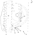
- a bearing block 8 is fastened to a frame 6 and can consist, for example, of a U-shaped canted sheet metal body which has two legs 14 spaced apart from one another.
- a chassis part 10 is held in the bearing block 8, which can be, for example, a trailing arm of an axle suspension, on which a rigid axle with wheels attached thereto is held. At its free end, the trailing arm can move up and down around the bearing pin 12 as a pivot bearing, as indicated by the double arrow, in order to avoid bumps in the road while driving.
- the bearing pin 12 is held in the legs 14 and the elongated holes 22 formed therein via at least one eccentric element 16 in a desired spatial orientation.
- the structure and functioning of the eccentric element 16 is described in more detail in the following figures.
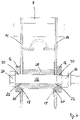
- In 2 is a sectional view through a bearing block 8 along the section line II-II in 1 shown in the area of the bearing pin 12.
- the two legs 14 of the bearing block 8 are clearly visible.
- an eccentric element 16 is placed from the outside.
- the eccentric elements 16 each have a rotary pin 18 on their side facing the legs 14 , which protrudes beyond the flat contact surface of the eccentric element 16 and is mounted in a rotary bearing 20 in each case.
- the pivot bearing 20 consists of a circular opening which is introduced into the material of the respective legs 14 .
- the shape of a pivot bearing 20 can also deviate from the circular shape and assume any other suitable shape.
- the rotary pin 18 and the rotary bearing 20 together form a rotary connection between the legs 14 of the bearing block 8 and the eccentric elements 16.
- the bearing pin 12 is in the in 2 sectional view shown inserted through two slots 22, which are each located in the legs 14 of the bearing block 8.
- the bearing bolt 12 has a screw head 24 at its first end, which rests on the side A of the eccentric element 16 that faces away from the bearing block 8 and this in 2 shown screwed position on the outwardly facing surface of the associated leg 14 is pressed.
- On the opposite side of the bearing pin 12 is provided with a nut 26 which also rests on the side A of the eccentric element 16 facing away from the bearing block 8 and the eccentric element 16 against the outward-facing side of the associated there Leg 14 presses.
- the screw head 24 and the screw nut 26 as clamping elements press the eccentric elements 16 so hard against the outwardly facing surfaces of the legs 14 that they can no longer rotate around the rotary pin 18 . They thus fix the bearing pin 12 in the current spatial alignment in the respective slotted holes 22 .
- a spacer sleeve 28 is pushed onto the bearing pin 12 in the space between the legs 14 . The clamping of the legs 14 by the clamping elements 24, 26 thus takes place against the end faces of the spacer sleeve 28.
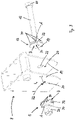
- FIG. 3 is a three-dimensional view of an embodiment of a device for adjusting the spatial position of a bearing pin 12 is shown before assembly.
- Leg 14 is in 3 shown only partially in the area of the connection with the eccentric element 16 .
- the eccentric element 16 has a passage opening 30 through which the bearing pin 12 has already been inserted.
- the rotary pin 18 can be seen, which is intended to be inserted into the rotary bearing 20, which is formed in the leg 14 at a suitable point.
- the eccentric element 16 can only move in a rotational movement around the pivot pin 18.
- the bearing pin 12 With such a movement, the bearing pin 12 would be carried along via the feed-through opening 30 with which the eccentric element 16 encompasses the bearing pin 12 . In this case, the bearing pin 12 would move in the longitudinal direction L in accordance with the respective direction of rotation in the slot 22 as long as the bearing pin 12 is not yet in contact with the end stops of a slot 22 .
- the slot 22 has in the in 3 shown embodiment in the direction of longitudinal extent L an arcuate course, since pivoting of the eccentric element 16 around the rotary pin 18 would also result in an arcuate movement of the bearing pin 12 . Since the arcuate course of the slot 22 follows the radius around the pivot bearing 20 and the pivot pin 18, the width of the slot 22 in the entire direction of longitudinal extent L can correspond to the diameter of the bearing pin 12, resulting in minimal tolerances between the edges of the slot 22 and the Diameter of the bearing pin 22 result. The ends of the elongated hole 22 form a stop for the bearing pin 12, which also limits the mobility of the eccentric element 16 when the pivot pin 18 is inserted into the pivot bearing 20.
- the eccentric element 16 has a total of six corners 34 on its peripheral contour 32 .
- the eccentric element 16 is therefore designed as a plate with a hexagonal basic shape.
- a tool 36 can be attached to the edge surfaces of the peripheral contour 32 , with which the eccentric element 16 can be rotated around the rotary pin 18 in order to move the bearing pin 12 along the longitudinal direction L of the elongated hole 22 .
- the tool 36 is thereby moved in a direction by which the bearing pin 12 is brought in the slot 22 in the desired direction.
- the corners 34 which are formed on the peripheral contour 32 of the eccentric element 16, interlock with the tool 36 during a rotary movement with the tool 36 about the axis of rotation of the rotary pin 18, so that comparatively high actuating forces are transmitted to the eccentric element 16 via these contact surfaces be able.
- the possible directions of rotation of the tool 36 are in 3 indicated by a double arrow.
- the bearing pin 12 is made 3 inserted with the eccentric element 16 resting on the screw head into the elongated hole 22 until the rotary pin 18 dips into the pivot bearing 20 .
- an eccentric element 16 can also be slid onto the outside of the associated leg 14 of the bearing block 8, again in such a way that the pivot pin 18 there also engages in the associated pivot bearing 20.
- a nut 26 can then be screwed onto the free end of the bearing pin 12 on the opposite side of the bearing block 8 .
- the eccentric element 16 can then be rotated back and forth with the tool 36 until the bearing pin 12 comes to rest in the slot 22 in a desired orientation. Then the clamping elements 24, 26 can be tightened to set both the bearing pin 12 and the eccentric elements 16 in the respectively assumed spatial position in the bearing block 8.
- the invention is not limited to the above exemplary embodiments. It is not difficult for a person skilled in the art to modify the exemplary embodiments in a manner that he deems suitable in order to adapt them to a specific application.
Landscapes
- Engineering & Computer Science (AREA)
- Mechanical Engineering (AREA)
- Vehicle Body Suspensions (AREA)
Applications Claiming Priority (1)
| Application Number | Priority Date | Filing Date | Title |
|---|---|---|---|
| DE102020131375.6A DE102020131375A1 (de) | 2020-11-26 | 2020-11-26 | Fahrwerksaufhängung mit exzentrischem Justierelement |
Publications (3)
| Publication Number | Publication Date |
|---|---|
| EP4005834A1 true EP4005834A1 (fr) | 2022-06-01 |
| EP4005834B1 EP4005834B1 (fr) | 2023-10-11 |
| EP4005834C0 EP4005834C0 (fr) | 2023-10-11 |
Family
ID=78806292
Family Applications (1)
| Application Number | Title | Priority Date | Filing Date |
|---|---|---|---|
| EP21210653.8A Active EP4005834B1 (fr) | 2020-11-26 | 2021-11-26 | Suspension de châssis pourvu d'élément d'ajustement excentrique |
Country Status (2)
| Country | Link |
|---|---|
| EP (1) | EP4005834B1 (fr) |
| DE (1) | DE102020131375A1 (fr) |
Families Citing this family (1)
| Publication number | Priority date | Publication date | Assignee | Title |
|---|---|---|---|---|
| US11845490B1 (en) * | 2023-03-01 | 2023-12-19 | Ford Global Technologies, Llc | Vehicle alignment assembly |
Citations (5)
| Publication number | Priority date | Publication date | Assignee | Title |
|---|---|---|---|---|
| US3960388A (en) | 1975-03-27 | 1976-06-01 | Lear Siegler, Inc. | Vehicle suspension system and alignment mechanism therefor |
| DE8716234U1 (de) * | 1987-05-16 | 1988-01-28 | Bergische Achsenfabrik Fr. Kotz & Söhne, 5276 Wiehl | Luftfederachse |
| EP0943529A1 (fr) * | 1998-03-17 | 1999-09-22 | Weweler Nederland B.V. | Dispositif de fixation pour un bras de support longitudinal d'un ensemble d' essieu suspendu de véhicule |
| US20060181044A1 (en) * | 2005-02-16 | 2006-08-17 | Zebolsky Michael L | Rotary cam alignment system |
| US20110068524A1 (en) | 2009-09-22 | 2011-03-24 | Mccarthy Robert E | Adjustable spring mounting assembly |
-
2020
- 2020-11-26 DE DE102020131375.6A patent/DE102020131375A1/de active Pending
-
2021
- 2021-11-26 EP EP21210653.8A patent/EP4005834B1/fr active Active
Patent Citations (5)
| Publication number | Priority date | Publication date | Assignee | Title |
|---|---|---|---|---|
| US3960388A (en) | 1975-03-27 | 1976-06-01 | Lear Siegler, Inc. | Vehicle suspension system and alignment mechanism therefor |
| DE8716234U1 (de) * | 1987-05-16 | 1988-01-28 | Bergische Achsenfabrik Fr. Kotz & Söhne, 5276 Wiehl | Luftfederachse |
| EP0943529A1 (fr) * | 1998-03-17 | 1999-09-22 | Weweler Nederland B.V. | Dispositif de fixation pour un bras de support longitudinal d'un ensemble d' essieu suspendu de véhicule |
| US20060181044A1 (en) * | 2005-02-16 | 2006-08-17 | Zebolsky Michael L | Rotary cam alignment system |
| US20110068524A1 (en) | 2009-09-22 | 2011-03-24 | Mccarthy Robert E | Adjustable spring mounting assembly |
Also Published As
| Publication number | Publication date |
|---|---|
| DE102020131375A1 (de) | 2022-06-02 |
| EP4005834B1 (fr) | 2023-10-11 |
| EP4005834C0 (fr) | 2023-10-11 |
Similar Documents
| Publication | Publication Date | Title |
|---|---|---|
| EP4005834B1 (fr) | Suspension de châssis pourvu d'élément d'ajustement excentrique | |
| DE1405837C3 (de) | Anordnung zum Befestigen eines Gegengewichtes an einem Hublader | |
| EP0306626B1 (fr) | Dispositif de réglage de la tringlerie de direction d'une roue | |
| DE2646026C2 (de) | Vorrichtung zur Umwandlung einer Rotationsbewegung in eine Hin- und Herbewegung | |
| DE4211765C2 (de) | Werkzeug zum Montieren und Demontieren von Gummilagern der Raumlenker und insbesondere des Achsträgers bei Kraftfahrzeugen | |
| DE3141158C2 (de) | Führungsvorrichtung für einen ein- und ausfahrbaren Einsatz im Korpus eines Schrankes | |
| DE1552780C3 (de) | Vorrichtung zum Richten unrunder Zahnkränze | |
| EP0250638A1 (fr) | Tendeur pour ressort de compression | |
| DE2520795B2 (de) | Vorrichtung zum Befestigen eines Schwingträgers am Hauptrahmen eines Fahrzeuges | |
| DE102015012641B3 (de) | Gelenkverbindung | |
| EP2784019B1 (fr) | Dispositif d'étayage par le dessous d'un moteur de véhicule automobile | |
| DE3521836C2 (de) | Vorrichtung zum Verstellen eines Fahrzeugsitzes | |
| DE9305933U1 (de) | Zwangsgesteuertes Türscharnier mit zwei Schwenkachsen | |
| DE8327478U1 (de) | Hydraulischer schraubenschluessel mit rolle | |
| DE3200879A1 (de) | "vorrichtung zur einstellung der schwenkachse eines gelenks zur schwenkfaehigen aufhaengung eines fuehrungslenkers zur fuehrung eines rades, insbesondere eines fahrzeughinterrades" | |
| DE69210572T2 (de) | Schnellwechselbare Abschneidescherenvorrichtung für eine Maschine zum Formen von Glasgegenständen | |
| DE1502359A1 (de) | Vorrichtung zum Abrichten von Schleifscheiben od.dgl. | |
| DE3517306A1 (de) | Vorrichtung zum ausrichten nebeneinander angeordneter schalungselemente | |
| DE2315982A1 (de) | Befestigungsvorrichtung fuer motoren, getriebegehaeuse, variatoren oder dgl., insbesondere fuer einen elektromotor, der bei einem maschinenwerkzeug oder dgl. eine riemenscheibe treibt | |
| DE3402809A1 (de) | Scharnierbefestigung fuer fahrzeugtueren | |
| WO2009080002A1 (fr) | Dispositif de réglage fin à broche filetée | |
| DE941728C (de) | Einrichtung zum Tragen der Klischees von Druckmaschinen fuer Bogen- oder Rotationsdruck | |
| DE102004034148B4 (de) | Gasheizstrahler in Form eines Terrassenstrahlers sowie schwenkbare Baugruppe hierzu | |
| WO2016202432A1 (fr) | Élément de liaison pour parties structurales d'un arbre à chat et arbre à chat comportant un tel élément de liaison | |
| DE1704263B1 (de) | Halterung fuer einen Schweissspiegel von Kunststoffschweissmaschinen |
Legal Events
| Date | Code | Title | Description |
|---|---|---|---|
| PUAI | Public reference made under article 153(3) epc to a published international application that has entered the european phase |
Free format text: ORIGINAL CODE: 0009012 |
|
| STAA | Information on the status of an ep patent application or granted ep patent |
Free format text: STATUS: THE APPLICATION HAS BEEN PUBLISHED |
|
| AK | Designated contracting states |
Kind code of ref document: A1 Designated state(s): AL AT BE BG CH CY CZ DE DK EE ES FI FR GB GR HR HU IE IS IT LI LT LU LV MC MK MT NL NO PL PT RO RS SE SI SK SM TR |
|
| STAA | Information on the status of an ep patent application or granted ep patent |
Free format text: STATUS: REQUEST FOR EXAMINATION WAS MADE |
|
| 17P | Request for examination filed |
Effective date: 20221129 |
|
| RBV | Designated contracting states (corrected) |
Designated state(s): AL AT BE BG CH CY CZ DE DK EE ES FI FR GB GR HR HU IE IS IT LI LT LU LV MC MK MT NL NO PL PT RO RS SE SI SK SM TR |
|
| GRAP | Despatch of communication of intention to grant a patent |
Free format text: ORIGINAL CODE: EPIDOSNIGR1 |
|
| STAA | Information on the status of an ep patent application or granted ep patent |
Free format text: STATUS: GRANT OF PATENT IS INTENDED |
|
| GRAS | Grant fee paid |
Free format text: ORIGINAL CODE: EPIDOSNIGR3 |
|
| INTG | Intention to grant announced |
Effective date: 20230504 |
|
| GRAA | (expected) grant |
Free format text: ORIGINAL CODE: 0009210 |
|
| STAA | Information on the status of an ep patent application or granted ep patent |
Free format text: STATUS: THE PATENT HAS BEEN GRANTED |
|
| AK | Designated contracting states |
Kind code of ref document: B1 Designated state(s): AL AT BE BG CH CY CZ DE DK EE ES FI FR GB GR HR HU IE IS IT LI LT LU LV MC MK MT NL NO PL PT RO RS SE SI SK SM TR |
|
| REG | Reference to a national code |
Ref country code: GB Ref legal event code: FG4D Free format text: NOT ENGLISH |
|
| REG | Reference to a national code |
Ref country code: CH Ref legal event code: EP |
|
| REG | Reference to a national code |
Ref country code: DE Ref legal event code: R096 Ref document number: 502021001689 Country of ref document: DE |
|
| REG | Reference to a national code |
Ref country code: IE Ref legal event code: FG4D Free format text: LANGUAGE OF EP DOCUMENT: GERMAN |
|
| U01 | Request for unitary effect filed |
Effective date: 20231012 |
|
| U07 | Unitary effect registered |
Designated state(s): AT BE BG DE DK EE FI FR IT LT LU LV MT NL PT SE SI Effective date: 20231023 |
|
| U20 | Renewal fee paid [unitary effect] |
Year of fee payment: 3 Effective date: 20231120 |
|
| PG25 | Lapsed in a contracting state [announced via postgrant information from national office to epo] |
Ref country code: GR Free format text: LAPSE BECAUSE OF FAILURE TO SUBMIT A TRANSLATION OF THE DESCRIPTION OR TO PAY THE FEE WITHIN THE PRESCRIBED TIME-LIMIT Effective date: 20240112 |
|
| PG25 | Lapsed in a contracting state [announced via postgrant information from national office to epo] |
Ref country code: IS Free format text: LAPSE BECAUSE OF FAILURE TO SUBMIT A TRANSLATION OF THE DESCRIPTION OR TO PAY THE FEE WITHIN THE PRESCRIBED TIME-LIMIT Effective date: 20240211 |
|
| PG25 | Lapsed in a contracting state [announced via postgrant information from national office to epo] |
Ref country code: ES Free format text: LAPSE BECAUSE OF FAILURE TO SUBMIT A TRANSLATION OF THE DESCRIPTION OR TO PAY THE FEE WITHIN THE PRESCRIBED TIME-LIMIT Effective date: 20231011 |
|
| PG25 | Lapsed in a contracting state [announced via postgrant information from national office to epo] |
Ref country code: IS Free format text: LAPSE BECAUSE OF FAILURE TO SUBMIT A TRANSLATION OF THE DESCRIPTION OR TO PAY THE FEE WITHIN THE PRESCRIBED TIME-LIMIT Effective date: 20240211 Ref country code: GR Free format text: LAPSE BECAUSE OF FAILURE TO SUBMIT A TRANSLATION OF THE DESCRIPTION OR TO PAY THE FEE WITHIN THE PRESCRIBED TIME-LIMIT Effective date: 20240112 Ref country code: ES Free format text: LAPSE BECAUSE OF FAILURE TO SUBMIT A TRANSLATION OF THE DESCRIPTION OR TO PAY THE FEE WITHIN THE PRESCRIBED TIME-LIMIT Effective date: 20231011 |
|
| PG25 | Lapsed in a contracting state [announced via postgrant information from national office to epo] |
Ref country code: RS Free format text: LAPSE BECAUSE OF FAILURE TO SUBMIT A TRANSLATION OF THE DESCRIPTION OR TO PAY THE FEE WITHIN THE PRESCRIBED TIME-LIMIT Effective date: 20231011 Ref country code: PL Free format text: LAPSE BECAUSE OF FAILURE TO SUBMIT A TRANSLATION OF THE DESCRIPTION OR TO PAY THE FEE WITHIN THE PRESCRIBED TIME-LIMIT Effective date: 20231011 Ref country code: NO Free format text: LAPSE BECAUSE OF FAILURE TO SUBMIT A TRANSLATION OF THE DESCRIPTION OR TO PAY THE FEE WITHIN THE PRESCRIBED TIME-LIMIT Effective date: 20240111 Ref country code: HR Free format text: LAPSE BECAUSE OF FAILURE TO SUBMIT A TRANSLATION OF THE DESCRIPTION OR TO PAY THE FEE WITHIN THE PRESCRIBED TIME-LIMIT Effective date: 20231011 |
|
| REG | Reference to a national code |
Ref country code: DE Ref legal event code: R097 Ref document number: 502021001689 Country of ref document: DE |
|
| PG25 | Lapsed in a contracting state [announced via postgrant information from national office to epo] |
Ref country code: CZ Free format text: LAPSE BECAUSE OF FAILURE TO SUBMIT A TRANSLATION OF THE DESCRIPTION OR TO PAY THE FEE WITHIN THE PRESCRIBED TIME-LIMIT Effective date: 20231011 |
|
| PG25 | Lapsed in a contracting state [announced via postgrant information from national office to epo] |
Ref country code: SK Free format text: LAPSE BECAUSE OF FAILURE TO SUBMIT A TRANSLATION OF THE DESCRIPTION OR TO PAY THE FEE WITHIN THE PRESCRIBED TIME-LIMIT Effective date: 20231011 |
|
| PG25 | Lapsed in a contracting state [announced via postgrant information from national office to epo] |
Ref country code: SM Free format text: LAPSE BECAUSE OF FAILURE TO SUBMIT A TRANSLATION OF THE DESCRIPTION OR TO PAY THE FEE WITHIN THE PRESCRIBED TIME-LIMIT Effective date: 20231011 Ref country code: SK Free format text: LAPSE BECAUSE OF FAILURE TO SUBMIT A TRANSLATION OF THE DESCRIPTION OR TO PAY THE FEE WITHIN THE PRESCRIBED TIME-LIMIT Effective date: 20231011 Ref country code: RO Free format text: LAPSE BECAUSE OF FAILURE TO SUBMIT A TRANSLATION OF THE DESCRIPTION OR TO PAY THE FEE WITHIN THE PRESCRIBED TIME-LIMIT Effective date: 20231011 Ref country code: CZ Free format text: LAPSE BECAUSE OF FAILURE TO SUBMIT A TRANSLATION OF THE DESCRIPTION OR TO PAY THE FEE WITHIN THE PRESCRIBED TIME-LIMIT Effective date: 20231011 |
|
| PLBE | No opposition filed within time limit |
Free format text: ORIGINAL CODE: 0009261 |
|
| STAA | Information on the status of an ep patent application or granted ep patent |
Free format text: STATUS: NO OPPOSITION FILED WITHIN TIME LIMIT |
|
| PG25 | Lapsed in a contracting state [announced via postgrant information from national office to epo] |
Ref country code: MC Free format text: LAPSE BECAUSE OF FAILURE TO SUBMIT A TRANSLATION OF THE DESCRIPTION OR TO PAY THE FEE WITHIN THE PRESCRIBED TIME-LIMIT Effective date: 20231011 |
|
| PG25 | Lapsed in a contracting state [announced via postgrant information from national office to epo] |
Ref country code: MC Free format text: LAPSE BECAUSE OF FAILURE TO SUBMIT A TRANSLATION OF THE DESCRIPTION OR TO PAY THE FEE WITHIN THE PRESCRIBED TIME-LIMIT Effective date: 20231011 |
|
| REG | Reference to a national code |
Ref country code: IE Ref legal event code: MM4A |
|
| 26N | No opposition filed |
Effective date: 20240712 |
|
| PG25 | Lapsed in a contracting state [announced via postgrant information from national office to epo] |
Ref country code: IE Free format text: LAPSE BECAUSE OF NON-PAYMENT OF DUE FEES Effective date: 20231126 |
|
| PG25 | Lapsed in a contracting state [announced via postgrant information from national office to epo] |
Ref country code: IE Free format text: LAPSE BECAUSE OF NON-PAYMENT OF DUE FEES Effective date: 20231126 |