EP4005722A1 - Ultrasonic horn, secondary battery, and method for manufacturing secondary battery - Google Patents
Ultrasonic horn, secondary battery, and method for manufacturing secondary battery Download PDFInfo
- Publication number
- EP4005722A1 EP4005722A1 EP20847933.7A EP20847933A EP4005722A1 EP 4005722 A1 EP4005722 A1 EP 4005722A1 EP 20847933 A EP20847933 A EP 20847933A EP 4005722 A1 EP4005722 A1 EP 4005722A1
- Authority
- EP
- European Patent Office
- Prior art keywords
- negative electrode
- protrusion
- foil
- exposed portion
- horn
- Prior art date
- Legal status (The legal status is an assumption and is not a legal conclusion. Google has not performed a legal analysis and makes no representation as to the accuracy of the status listed.)
- Granted
Links
Images



Classifications
-
- H—ELECTRICITY
- H01—ELECTRIC ELEMENTS
- H01M—PROCESSES OR MEANS, e.g. BATTERIES, FOR THE DIRECT CONVERSION OF CHEMICAL ENERGY INTO ELECTRICAL ENERGY
- H01M10/00—Secondary cells; Manufacture thereof
- H01M10/04—Construction or manufacture in general
- H01M10/0431—Cells with wound or folded electrodes
-
- B—PERFORMING OPERATIONS; TRANSPORTING
- B23—MACHINE TOOLS; METAL-WORKING NOT OTHERWISE PROVIDED FOR
- B23K—SOLDERING OR UNSOLDERING; WELDING; CLADDING OR PLATING BY SOLDERING OR WELDING; CUTTING BY APPLYING HEAT LOCALLY, e.g. FLAME CUTTING; WORKING BY LASER BEAM
- B23K20/00—Non-electric welding by applying impact or other pressure, with or without the application of heat, e.g. cladding or plating
- B23K20/10—Non-electric welding by applying impact or other pressure, with or without the application of heat, e.g. cladding or plating making use of vibrations, e.g. ultrasonic welding
-
- B—PERFORMING OPERATIONS; TRANSPORTING
- B23—MACHINE TOOLS; METAL-WORKING NOT OTHERWISE PROVIDED FOR
- B23K—SOLDERING OR UNSOLDERING; WELDING; CLADDING OR PLATING BY SOLDERING OR WELDING; CUTTING BY APPLYING HEAT LOCALLY, e.g. FLAME CUTTING; WORKING BY LASER BEAM
- B23K20/00—Non-electric welding by applying impact or other pressure, with or without the application of heat, e.g. cladding or plating
- B23K20/10—Non-electric welding by applying impact or other pressure, with or without the application of heat, e.g. cladding or plating making use of vibrations, e.g. ultrasonic welding
- B23K20/106—Features related to sonotrodes
-
- B—PERFORMING OPERATIONS; TRANSPORTING
- B23—MACHINE TOOLS; METAL-WORKING NOT OTHERWISE PROVIDED FOR
- B23K—SOLDERING OR UNSOLDERING; WELDING; CLADDING OR PLATING BY SOLDERING OR WELDING; CUTTING BY APPLYING HEAT LOCALLY, e.g. FLAME CUTTING; WORKING BY LASER BEAM
- B23K20/00—Non-electric welding by applying impact or other pressure, with or without the application of heat, e.g. cladding or plating
- B23K20/22—Non-electric welding by applying impact or other pressure, with or without the application of heat, e.g. cladding or plating taking account of the properties of the materials to be welded
- B23K20/233—Non-electric welding by applying impact or other pressure, with or without the application of heat, e.g. cladding or plating taking account of the properties of the materials to be welded without ferrous layer
- B23K20/2333—Non-electric welding by applying impact or other pressure, with or without the application of heat, e.g. cladding or plating taking account of the properties of the materials to be welded without ferrous layer one layer being aluminium, magnesium or beryllium
-
- B—PERFORMING OPERATIONS; TRANSPORTING
- B23—MACHINE TOOLS; METAL-WORKING NOT OTHERWISE PROVIDED FOR
- B23K—SOLDERING OR UNSOLDERING; WELDING; CLADDING OR PLATING BY SOLDERING OR WELDING; CUTTING BY APPLYING HEAT LOCALLY, e.g. FLAME CUTTING; WORKING BY LASER BEAM
- B23K20/00—Non-electric welding by applying impact or other pressure, with or without the application of heat, e.g. cladding or plating
- B23K20/26—Auxiliary equipment
-
- B—PERFORMING OPERATIONS; TRANSPORTING
- B23—MACHINE TOOLS; METAL-WORKING NOT OTHERWISE PROVIDED FOR
- B23K—SOLDERING OR UNSOLDERING; WELDING; CLADDING OR PLATING BY SOLDERING OR WELDING; CUTTING BY APPLYING HEAT LOCALLY, e.g. FLAME CUTTING; WORKING BY LASER BEAM
- B23K37/00—Auxiliary devices or processes, not specially adapted for a procedure covered by only one of the other main groups of this subclass
- B23K37/04—Auxiliary devices or processes, not specially adapted for a procedure covered by only one of the other main groups of this subclass for holding or positioning work
- B23K37/0408—Auxiliary devices or processes, not specially adapted for a procedure covered by only one of the other main groups of this subclass for holding or positioning work for planar work
-
- H—ELECTRICITY
- H01—ELECTRIC ELEMENTS
- H01M—PROCESSES OR MEANS, e.g. BATTERIES, FOR THE DIRECT CONVERSION OF CHEMICAL ENERGY INTO ELECTRICAL ENERGY
- H01M10/00—Secondary cells; Manufacture thereof
- H01M10/05—Accumulators with non-aqueous electrolyte
- H01M10/058—Construction or manufacture
- H01M10/0587—Construction or manufacture of accumulators having only wound construction elements, i.e. wound positive electrodes, wound negative electrodes and wound separators
-
- H—ELECTRICITY
- H01—ELECTRIC ELEMENTS
- H01M—PROCESSES OR MEANS, e.g. BATTERIES, FOR THE DIRECT CONVERSION OF CHEMICAL ENERGY INTO ELECTRICAL ENERGY
- H01M4/00—Electrodes
- H01M4/02—Electrodes composed of, or comprising, active material
- H01M4/04—Processes of manufacture in general
- H01M4/043—Processes of manufacture in general involving compressing or compaction
-
- H—ELECTRICITY
- H01—ELECTRIC ELEMENTS
- H01M—PROCESSES OR MEANS, e.g. BATTERIES, FOR THE DIRECT CONVERSION OF CHEMICAL ENERGY INTO ELECTRICAL ENERGY
- H01M50/00—Constructional details or processes of manufacture of the non-active parts of electrochemical cells other than fuel cells, e.g. hybrid cells
- H01M50/50—Current conducting connections for cells or batteries
- H01M50/531—Electrode connections inside a battery casing
- H01M50/536—Electrode connections inside a battery casing characterised by the method of fixing the leads to the electrodes, e.g. by welding
-
- H—ELECTRICITY
- H01—ELECTRIC ELEMENTS
- H01M—PROCESSES OR MEANS, e.g. BATTERIES, FOR THE DIRECT CONVERSION OF CHEMICAL ENERGY INTO ELECTRICAL ENERGY
- H01M50/00—Constructional details or processes of manufacture of the non-active parts of electrochemical cells other than fuel cells, e.g. hybrid cells
- H01M50/50—Current conducting connections for cells or batteries
- H01M50/531—Electrode connections inside a battery casing
- H01M50/538—Connection of several leads or tabs of wound or folded electrode stacks
-
- B—PERFORMING OPERATIONS; TRANSPORTING
- B23—MACHINE TOOLS; METAL-WORKING NOT OTHERWISE PROVIDED FOR
- B23K—SOLDERING OR UNSOLDERING; WELDING; CLADDING OR PLATING BY SOLDERING OR WELDING; CUTTING BY APPLYING HEAT LOCALLY, e.g. FLAME CUTTING; WORKING BY LASER BEAM
- B23K2101/00—Articles made by soldering, welding or cutting
- B23K2101/36—Electric or electronic devices
-
- B—PERFORMING OPERATIONS; TRANSPORTING
- B23—MACHINE TOOLS; METAL-WORKING NOT OTHERWISE PROVIDED FOR
- B23K—SOLDERING OR UNSOLDERING; WELDING; CLADDING OR PLATING BY SOLDERING OR WELDING; CUTTING BY APPLYING HEAT LOCALLY, e.g. FLAME CUTTING; WORKING BY LASER BEAM
- B23K2103/00—Materials to be soldered, welded or cut
- B23K2103/08—Non-ferrous metals or alloys
- B23K2103/10—Aluminium or alloys thereof
-
- B—PERFORMING OPERATIONS; TRANSPORTING
- B23—MACHINE TOOLS; METAL-WORKING NOT OTHERWISE PROVIDED FOR
- B23K—SOLDERING OR UNSOLDERING; WELDING; CLADDING OR PLATING BY SOLDERING OR WELDING; CUTTING BY APPLYING HEAT LOCALLY, e.g. FLAME CUTTING; WORKING BY LASER BEAM
- B23K2103/00—Materials to be soldered, welded or cut
- B23K2103/08—Non-ferrous metals or alloys
- B23K2103/12—Copper or alloys thereof
-
- B—PERFORMING OPERATIONS; TRANSPORTING
- B23—MACHINE TOOLS; METAL-WORKING NOT OTHERWISE PROVIDED FOR
- B23K—SOLDERING OR UNSOLDERING; WELDING; CLADDING OR PLATING BY SOLDERING OR WELDING; CUTTING BY APPLYING HEAT LOCALLY, e.g. FLAME CUTTING; WORKING BY LASER BEAM
- B23K2103/00—Materials to be soldered, welded or cut
- B23K2103/18—Dissimilar materials
-
- Y—GENERAL TAGGING OF NEW TECHNOLOGICAL DEVELOPMENTS; GENERAL TAGGING OF CROSS-SECTIONAL TECHNOLOGIES SPANNING OVER SEVERAL SECTIONS OF THE IPC; TECHNICAL SUBJECTS COVERED BY FORMER USPC CROSS-REFERENCE ART COLLECTIONS [XRACs] AND DIGESTS
- Y02—TECHNOLOGIES OR APPLICATIONS FOR MITIGATION OR ADAPTATION AGAINST CLIMATE CHANGE
- Y02E—REDUCTION OF GREENHOUSE GAS [GHG] EMISSIONS, RELATED TO ENERGY GENERATION, TRANSMISSION OR DISTRIBUTION
- Y02E60/00—Enabling technologies; Technologies with a potential or indirect contribution to GHG emissions mitigation
- Y02E60/10—Energy storage using batteries
-
- Y—GENERAL TAGGING OF NEW TECHNOLOGICAL DEVELOPMENTS; GENERAL TAGGING OF CROSS-SECTIONAL TECHNOLOGIES SPANNING OVER SEVERAL SECTIONS OF THE IPC; TECHNICAL SUBJECTS COVERED BY FORMER USPC CROSS-REFERENCE ART COLLECTIONS [XRACs] AND DIGESTS
- Y02—TECHNOLOGIES OR APPLICATIONS FOR MITIGATION OR ADAPTATION AGAINST CLIMATE CHANGE
- Y02P—CLIMATE CHANGE MITIGATION TECHNOLOGIES IN THE PRODUCTION OR PROCESSING OF GOODS
- Y02P70/00—Climate change mitigation technologies in the production process for final industrial or consumer products
- Y02P70/50—Manufacturing or production processes characterised by the final manufactured product
Definitions
- the present invention relates to an ultrasonic horn for ultrasonically bonding a plurality of stacked sheets of metal foil and a metal member by sandwiching the plurality of stacked sheets of metal foil and the metal member with an anvil and applying ultrasonic vibration to the plurality of stacked sheets of metal foil; a secondary battery; and a method for manufacturing a secondary battery.
- a lithium ion secondary battery having a high energy density has been developed as a power source of an electric vehicle, for example.
- a secondary battery mounted on a vehicle or the like a rectangular secondary battery having a high volume density is known.
- a positive electrode having a positive electrode active material applied on both surfaces of a positive electrode foil and a negative electrode having a negative electrode active material applied on both surfaces of a negative electrode foil are wound in a flat shape, with a separator interposed therebetween, and the winding body (i.e., electrode group) is housed in a rectangular battery case.
- an energizing path is minimized to reduce the connection resistance by forming metal-foil-exposed portions, in which a positive electrode metal foil and a negative electrode metal foil are exposed respectively at the opposite end portions of the winding body in the winding axis direction, and then connecting electrode terminals and collectors to these metal-foil-exposed portions by welding or the like.
- Patent Literature 1 discloses a method for performing ultrasonic welding by arranging a protective metal plate on an upper side on a horn abutting side of the large number of stacked sheets of metal foil.
- Patent Literature 2 discloses that a distal end portion on a side of the object to be joined of the resonator is configured such that a plurality of protrusions each having an outer face not including an angular shape edge are stacked in two or more steps.
- arranging a protective metal plate on the horn abutting side in ultrasonic bonding may increase the number of components and the number of manufacturing steps. Furthermore, additional bonding of the protective plate may increase the thickness of the joint part, which requires a longer time for bonding as compared to the case of not using a protective plate.
- the present invention has been made in view of the foregoing, and provides an ultrasonic horn, a secondary battery, and a method for manufacturing a secondary battery that can reduce the likelihood of damaging a plurality of stacked sheets of metal foil when the stacked sheets of metal foil and a metal member are ultrasonically bonded by applying ultrasonic vibration to the stacked sheets of metal foil, without using a protective metal plate.
- an ultrasonic horn for ultrasonically bonding a plurality of stacked sheets of metal foil and a metal member by sandwiching the plurality of stacked sheets of metal foil and the metal member with an anvil and applying ultrasonic vibration in a state where the ultrasonic horn abuts on the plurality of stacked sheets of metal foil
- the ultrasonic horn including: a horn body, a first protrusion having a first surface that is a curved surface and protruding from an opposing surface of the horn body facing the anvil toward the anvil, and a second protrusion provided at a center of the first surface of the first protrusion and protruding toward the anvil.
- the second protrusion includes an end surface that is a planar surface and a second surface that is a curved surface connecting the end surface and the first surface of the first protrusion.
- an ultrasonic horn a secondary battery
- a method for manufacturing a secondary battery that can reduce the likelihood of damaging a plurality of stacked sheets of metal foil when the plurality of stacked sheets of metal foil and a metal member are ultrasonically bonded, without using a protective metal plate.
- a rectangular secondary battery manufactured by using the ultrasonic horn according to one embodiment of the present invention will be described with reference to Fig. 1 to Fig. 3 .
- an example of applying a rectangular secondary battery 20 to a lithium ion secondary battery will be described.
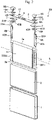
- Fig. 1 is an external perspective view of a rectangular secondary battery manufactured by using an ultrasonic horn according to one embodiment of the present invention.
- Fig. 2 is an exploded perspective view of a rectangular secondary battery manufactured by using an ultrasonic horn according to one embodiment of the present invention.
- the rectangular secondary battery 20 includes a battery case 1 and a lid 6.
- the battery case 1 houses an electrode group 3 serving as a power generator, and the upper opening of the battery case 1 is sealed with the lid 6.
- the lid 6 is welded to the battery case 1 by laser welding.
- the battery case 1 and the lid 6 form a battery container.
- the lid 6 is provided with a positive electrode external terminal 8A and a negative electrode external terminal 8B. Via the positive electrode external terminal 8A and the negative electrode external terminal 8B, the electrode group 3 is charged, and electric power is supplied to an external load.
- the lid 6 is integrally provided with a gas discharge valve 10. When a pressure increases in the battery container, the gas discharge valve 10 opens, and gas is discharged from the inside of the battery container to reduce the pressure in the battery container, such that the safety of the rectangular secondary battery 20 is ensured.
- a liquid injection plug 11 is welded to the lid 6 to seal a liquid injection port 9 for injecting an electrolyte into the battery case 1.
- the battery case 1 of the rectangular secondary battery 20 houses the electrode group 3 via an insulating sheet 2.
- a positive electrode body (positive electrode) 301 and a negative electrode body (negative electrode) 302 are wound about a winding axis L in a flat shape with a separator 303 (see Fig. 3 for all of them) interposed therebetween.
- the electrode group 3 includes a pair of bent portions 3a, 3b each having a substantially semicircular cross section that are opposed to each other, and a flat surface portion 3c continuously formed between the pair of bent portions 3a, 3b.
- the electrode group 3 includes a positive electrode side bundled portion 301d and a negative electrode side bundled portion 302d, which are formed by at least partially bundling in a flat plate shape a positive electrode foil-exposed portion 301c and a negative electrode foil-exposed portion 302c (see Fig. 3 for them) serving as the flat surface portion 3c of the electrode group 3 and metal-foil-exposed portions (described later).
- the positive electrode side bundled portion 301d and the negative electrode side bundled portion 302d are respectively overlaid with and connected to one end (connection portion 42A) of a positive electrode collector plate 4A and one end (connection portion 42B) of a negative electrode collector plate 4B by welding or the like.
- the positive electrode collector plate 4A and the negative electrode collector plate 4B are one example of the "metal member" of the present invention.
- the electrode group 3 is inserted into the battery case 1 from the bent portion 3b, which is one of the pair of bent portions 3a, 3b, such that the winding axis L direction of the electrode group 3 is along the lateral width of the battery case 1, and the bent portion 3a, which is the other one of the pair of bent portions 3a, 3b, is disposed so as to be adjacent to an upper opening 1a of the battery case 1.
- the other end (upper end) of the positive electrode collector plate 4A and the other end (upper end) of the negative electrode collector plate 4B are connected to the positive electrode external terminal 8A and the negative electrode external terminal 8B, respectively.
- the positive electrode external terminal 8A and the negative electrode external terminal 8B each have a weld joint part to be joined by welding to a bus bar or the like (not shown).
- the weld joint part has a rectangular parallelepiped block shape protruding upward from the lid 6, and is configured such that the lower surface thereof faces the surface of the lid 6, and the upper surface thereof is in parallel with the lid 6 at a predetermined height position.
- a positive electrode connection portion 12A for connecting the positive electrode external terminal 8A and the positive electrode collector plate 4A is integrally formed with the lower surface of the weld joint part of the positive electrode external terminal 8A.
- a negative electrode connection portion 12B for connecting the negative electrode external terminal 8B and the negative electrode collector plate 4B is integrally formed with the lower surface of the weld joint part of the negative electrode external terminal 8B.
- the positive electrode collector plate 4A and the negative electrode collector plate 4B respectively include rectangular plate-like base portions 41A, 41B disposed to face the lower surface of the lid 6.
- the base portions 41A, 41B respectively have opening holes 43A, 43B through which the positive electrode connection portion 12A formed on the positive electrode external terminal 8A and the negative electrode connection portion 12B formed on the negative electrode external terminal 8B are inserted, respectively.
- the positive electrode collector plate 4A and the negative electrode collector plate 4B are bent at the side ends of the base portions 41A, 41B and extend toward the bottom surface of the battery case 1 along the wider surface of the battery case 1.
- the positive electrode collector plate 4A and the negative electrode collector plate 4B respectively include connection portions 42A, 42B to be connected to the positive electrode side bundled portion 301d and the negative electrode side bundled portion 302d of the electrode group 3, respectively, in a state where the positive electrode collector plate 4A and the negative electrode collector plate 4B are opposed to and overlaid with the positive electrode side bundled portion 301d and the negative electrode side bundled portion 302d.
- the positive electrode connection portion 12A of the positive electrode external terminal 8A and the negative electrode connection portion 12B of the negative electrode external terminal 8B have a cylindrical shape such that the end of the positive electrode external terminal 8A and the end of the negative electrode external terminal 8B protruding from their respective lower surfaces can be inserted into through-holes 6A, 6B formed on the lid 6, respectively.
- the positive electrode connection portion 12A and the negative electrode connection portion 12B penetrate the lid 6 through the through-holes 6A, 6B, and protrude toward the inner part of the battery case 1 beyond the base portions 41A, 41B of the positive electrode collector plate 4A and the negative electrode collector plate 4B through the opening holes 43A, 43B.
- the positive electrode connection portion 12A and the negative electrode connection portion 12B are swaged at their ends so as to integrally fix the positive electrode external terminal 8A and the positive electrode collector plate 4A to the lid 6, and the negative electrode external terminal 8B and the negative electrode collector plate 4B to the lid 6.
- a gasket 5 is interposed between the positive electrode external terminal 8A and the lid 6 and between the negative electrode external terminal 8B and the lid 6, and an insulating plate 7 is interposed between the positive electrode collector plate 4A and the lid 6 and between the negative electrode collector plate 4B and the lid 6.
- the gaskets 5 and the insulating plates 7 electrically insulate the positive electrode external terminal 8A, the negative electrode external terminal 8B, the positive electrode collector plate 4A, and the negative electrode collector plate 4B from the lid 6.
- a liquid injection port 9 is formed on the lid 6, and after an electrolyte is injected from the liquid injection port 9 into the battery case 1, a liquid injection plug 11 is welded to the liquid injection port 9, so as to hermetically seal the rectangular secondary battery 20.
- the positive electrode collector plate 4A includes a current interruption portion 101 configured to interrupt current when an excessive current flows into an intermediate portion of the positive electrode collector plate 4A.
- the current interruption portion 101 is formed by narrowing some portion of the positive electrode collector plate 4A, for example, and when such a portion is blown out by the excessive current, the positive electrode collector plate 4A is able to be separated into a portion adjacent to the electrode group 3 and a portion adjacent to the positive electrode external terminal 8A.
- the current interruption portion 101 may be formed on the negative electrode collector plate 4B, or may be formed on each of the positive electrode collector plate 4A and the negative electrode collector plate 4B. As long as the current interruption portion 101 can interrupt current flowing through a current collector plate when an excessive current flows, the configuration of the current interruption portion 101 is not limited to the above-described configuration.
- the battery case 1, the lid 6, the positive electrode collector plate 4A, and the positive electrode external terminal 8A are made of aluminum or an aluminum alloy, and the negative electrode collector plate 4B and the negative electrode external terminal 8B are made of copper or a copper alloy.
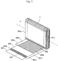
- Fig. 3 is a perspective view of the electrode group 3 shown in Fig. 2 , a part of which is expanded. It should be noted that Fig. 3 shows a state of the electrode group 3 before the metal-foil-exposed portions (i.e., the positive electrode foil-exposed portion 301c, the negative electrode foil-exposed portion 302c) of the positive electrode body (positive electrode) 301 and the negative electrode body (negative electrode) 302 are bundled and bonded.
- the metal-foil-exposed portions i.e., the positive electrode foil-exposed portion 301c, the negative electrode foil-exposed portion 302c
- the electrode group 3 is formed by winding in a flat shape the positive electrode body 301 and the negative electrode body 302 about the winding axis L with the separator 303 interposed therebetween.
- the positive electrode body 301 includes an active material layer that is formed by applying a positive electrode mixture 301b on both surfaces of a positive electrode foil (metal foil) 301a, and the end portion of the positive electrode foil 301a on one side in the width direction (i.e., winding axis L direction) includes the positive electrode foil-exposed portion (metal-foil-exposed portion) 301c on which the positive electrode mixture 301b is not applied and the positive electrode foil 301a is exposed.
- the negative electrode body 302 includes an active material layer that is formed by applying a negative electrode mixture 302b on both surfaces of a negative electrode foil (metal foil) 302a, and the end portion of the negative electrode foil 302a on the other side in the width direction (i.e., winding axis L direction) includes the negative electrode foil-exposed portion (metal-foil-exposed portion) 302c on which the negative electrode mixture 302b is not applied and the negative electrode foil 302a is exposed.
- the positive electrode body 301 and the negative electrode body 302 are wound about the winding axis L such that the positive electrode foil-exposed portion 301c and the negative electrode foil-exposed portion 302c are disposed on opposite sides to each other in the winding axis L direction.
- the negative electrode body 302 PolyVinylidene Difluoride (PVDF) as a binder is added to amorphous carbon powder with a mass ratio of amorphous carbon powder to PVDF of 10:1, and N-methylpyrrolidone (NMP) as a dispersing solvent is further added and kneaded to prepare the negative electrode mixture 302b.
- the negative electrode mixture 302b is applied to both surfaces of a copper foil (negative electrode foil 302a) having a thickness of 10 ⁇ m, with a current collector portion (i.e., negative electrode foil-exposed portion 302c) left. Then, after drying, pressing, and cutting steps, the negative electrode body 302 having a thickness of 70 ⁇ m excluding the copper foil is obtained.
- examples of the negative electrode mixture may include natural graphite into/from which lithium ions can be insert/removed, various artificial graphite materials, a carbonaceous material such as coke, or the like.
- examples of the particle form thereof may include a scaly form, a spherical form, a fibrous form, a massive form, or the like.
- the positive electrode body 301 For the positive electrode body 301, scaly graphite as a conductive material and PVDF as a binder are added to lithium manganese oxide (LiMn 2 O 4 ) with a mass ratio of LiMn 2 O 4 to scaly graphite to PVDF of 10:1:1, and the NMP as a dispersing solvent is further added and kneaded to prepare the positive electrode mixture 301b.
- the positive electrode mixture 301b is applied to both surfaces of an aluminum foil (positive electrode foil 301a) having a thickness of 20 ⁇ m, with a current collector portion (i.e., positive electrode foil-exposed portion 301c) left. Then, after drying, pressing, and cutting steps, the positive electrode body 301 having a thickness of 90 ⁇ m excluding the aluminum foil is obtained.
- examples of the positive electrode mixture may include another lithium manganese oxide having a spinel crystal structure, a lithium manganese composite oxide in which the lithium manganese oxide is partially substituted by or doped with a metal element, a lithium cobaltite or a lithium titanate having a layered crystal structure, or a lithium-metal composite oxide in which the lithium cobaltite or lithium titanate is partially substituted by or doped with a metal element.
- examples of the binder may include a polymer, a mixture, and the like of polytetrafluoroethylene, polyethylene, polystyrene, polybutadiene, butyl rubber, nitrile rubber, styrene butadiene rubber, polysulfide rubber, nitrocellulose, cyanoethyl cellulose, various kinds of latex, acrylonitrile, vinyl fluoride, vinylidene fluoride, propylene fluoride, chloroprene fluoride, acrylic-based resin, and the like.
- Fig. 4 is a view schematically showing the step of bonding a current collector plate to the electrode group shown in Fig. 3 .
- the bonding step is not limited to bonding a metal foil made of copper and a current collector plate, and is also applicable to bonding a metal foil made of aluminum and a current collector plate, and further to bonding a metal foil made of material other than copper and aluminum and a current collector plate.
- connection portion 42B of the negative electrode collector plate 4B is disposed on one side 302e of the negative electrode side bundled portion 302d that is formed by bundling the negative electrode foil-exposed portion 302c of the electrode group 3 in a flat plate shape, and then through ultrasonic bonding, the negative electrode foil-exposed portion 302c of the electrode group 3 and the connection portion 42B of the negative electrode collector plate 4B are bonded together in a state where their respective flat surface portions abut on each other.
- an ultrasonic bonding apparatus 500 for bonding the negative electrode foil-exposed portion 302c and the connection portion 42B of the negative electrode collector plate 4B includes a horn (ultrasonic horn) 510, an anvil 520 disposed to face the horn 510, and a horn drive unit (not shown) for driving the horn 510.
- connection portion 42B of the negative electrode collector plate 4B is disposed on the anvil 520 of the ultrasonic bonding apparatus 500, and the negative electrode foil-exposed portion 302c is disposed on the connection portion 42B. Then, in a state where the horn 510 and the anvil 520 sandwich therebetween the negative electrode side bundled portion 302d of the negative electrode foil-exposed portion 302c and the connection portion 42B, the horn 510 is ultrasonically vibrated while being pressed against the negative electrode side bundled portion 302d.
- connection portion 42B and the negative electrode foil-exposed portion 302c This removes an oxide film on the surface of the connection portion 42B and the negative electrode foil-exposed portion 302c and facilitates atomic diffusion with frictional heat generated by the vibration, whereby the connection portion 42B and the negative electrode foil-exposed portion 302c are ultrasonically bonded.
- the horn 510 includes a horn body 511 in a substantially rectangular parallelepiped, a first protrusion 512 that protrudes from an opposing surface 511a of the horn body 511, which is a flat surface facing the anvil 520, toward the anvil 520 (see Fig. 4 ), and a second protrusion 513 that is provided at the center (i.e., the furthest portion from the horn body 511) of a first surface 512a of the first protrusion 512 and protrudes toward the anvil 520.
- a plurality of (e.g., three in this example) first protrusions 512 is provided and arranged on a straight line in a direction perpendicular to the paper surface of Fig. 4 , that is, in a longitudinal direction of the negative electrode collector plate 4B shown in Fig. 2 .
- Providing the plurality of first protrusions 512 allows the negative electrode foil-exposed portion 302c and the negative electrode collector plate 4B to be bonded together at a plurality of positions, thereby increasing the reliability of connection between the negative electrode foil-exposed portion 302c and the negative electrode collector plate 4B in the long view.
- the horn body 511 includes three first protrusions 512 in the present embodiment, the number of first protrusions 512 is not particularly limited. As can be seen from Example 8, which will be described later, providing only one first protrusion 512 can increase the connection reliability, and at least one first protrusion 512 is simply required. It should be noted that examples of the material of the horn 510 may include, but not particularly limited to, an aluminum alloy or a titanium alloy. Examples of a method for manufacturing the horn 510 may include, but not particularly limited to, sintering or casting. Although the horn body 511, the first protrusion 512, and the second protrusion 513 are integrally formed, the first protrusion 512 and the second protrusion 513 may be integrally formed and then fixed to the horn body 511.
- the first protrusion 512 is formed of a part of a sphere.
- the first surface 512a of the first protrusion 512 is a curved surface, which is a part of the spherical surface in this example.
- an angle ⁇ 1 defined by the first surface 512a and the opposing surface 511a may be, but not particularly limited to, 60° or less, specifically, 30° or less. This is because, as the angle ⁇ 1 decreases, a force in vibration directions (i.e., right-and-left directions in Fig. 4 ) to be applied to the negative electrode foil-exposed portion 302c decreases when the horn 510 is vibrated, and the likelihood of damaging the negative electrode foil-exposed portion 302c can be reduced.
- the angle ⁇ 1 may be 5° or greater. As the angle ⁇ 1 is closer to 0°, a force to be applied from the first protrusion 512 to the negative electrode foil-exposed portion 302c is distributed. Then, a force to be applied to a portion of the negative electrode foil-exposed portion 302c adjacent to the second protrusion 513 decreases, thereby reducing the tight contact between the stacked sheets of negative electrode foil-exposed portion 302c. For this reason, setting the angle ⁇ 1 to 5° or greater can easily ensure the tight contact between the stacked sheets of negative electrode foil-exposed portion 302c.
- the second protrusion 513 is formed of a part of a truncated cone.
- the second protrusion 512 includes an end surface (i.e., the lower surface in Fig. 7 ) 513b, which is a planar surface disposed in the furthest position from the horn body 511, and a second surface 513a connecting the end surface 513b and the first surface 512a of the first protrusion 512.
- the second surface 512a is a curved surface and is formed of a part of the conical surface.
- the second protrusion 513 ultrasonically vibrates while pressing the negative electrode foil-exposed portion 302c, whereby the stacked sheets of negative electrode foil-exposed portion 302c are firmly bonded together, and also the negative electrode foil-exposed portion 302c and the negative electrode collector plate 4B are firmly bonded together.
- an angle ⁇ 2 of the second surface 513a with respect to the opposing surface 511a may be, but not particularly limited to, 60° or less, specifically, 35° or less. This is because, as the angle ⁇ 2 decreases, a force in vibration directions (i.e., right-and-left directions in Fig. 4 ) to be applied to the negative electrode foil-exposed portion 302c decreases when the horn 510 is vibrated, and the likelihood of damaging the negative electrode foil-exposed portion 302c can be reduced.
- the angle ⁇ 2 may be 15° or greater.
- the second surface 513a In order to provide the second protrusion 513 on the first surface 512a, which is formed of a part of the spherical surface, the second surface 513a needs to have an inclination angle greater than that of the first surface 512a. Setting the angle ⁇ 2 to 15° or greater can easily form the second protrusion 513 so as to protrude downward relative to the first surface 512a, which is formed of a part of the spherical surface.
- the end surface 513b which is a planar surface, is formed so as to be in parallel with the opposing surface 511a of the horn body 511 and the vibration directions of the horn 510.
- the end surface 513b can prevent the force to be applied from the end surface 513b to the negative electrode foil-exposed portion 302c from concentrating on one point. Since shearing stress generated in the negative electrode foil-exposed portion 302c will not concentrate on one point, the likelihood of damaging the negative electrode foil-exposed portion 302c can be reduced.
- the upper sheet of the negative electrode foil-exposed portion 302c i.e., the negative electrode foil-exposed portion 302c adjacent to the horn 510 among the plurality of sheets of negative electrode foil-exposed portion 302c has a larger deformation amount, and the uppermost sheet of the negative electrode foil-exposed portion 302c among the plurality of sheets of negative electrode foil-exposed portion 302c has the largest deformation amount.
- the uppermost sheet of the negative electrode foil-exposed portion 302c has the smallest thickness.
- Fig. 9 is a cross-sectional view showing the negative electrode foil-exposed portion 302c being pressed by the horn, which includes a hemispherical end of the second protrusion 513 instead of a planar end, unlike the one in the present embodiment.
- the portion of the negative electrode foil-exposed portion 302c being pressed by the end of the second protrusion 513 will have a much smaller thickness since it has a much larger deformation amount as compared to the case where the portion of the negative electrode foil-exposed portion 302c is pressed by the end surface 513b of the present embodiment. Therefore, it is more likely that applying ultrasonic vibration to the negative electrode foil-exposed portion 302c by using the second protrusion 513 having a hemispherical end shown in Fig.
- the area of the end surface 513b may be, but not particularly limited to, 0.05 mm 2 or larger and 1.15 mm 2 or smaller. Setting the area of the end surface 513b to 0.05 mm 2 or larger can distribute the force to be applied from the second protrusion 513 to the negative electrode foil-exposed portion 302c when the negative electrode foil-exposed portion 302c and the negative electrode collector plate 4B are bonded together, and thus the likelihood of damaging the negative electrode foil-exposed portion 302c can easily be reduced.
- first protrusions 512 is disposed at predetermined intervals (for example, 0.3 mm or larger).
- the interval W (see Fig. 6 ) between the adjacent first protrusions 512 may be, but not particularly limited to, 0.3 mm or larger. This is because when the first protrusions 512 are pressed against the negative electrode side bundled portion 302d, the first protrusions 512 cause the negative electrode foil-exposed portion 302c to deform. At this time, the negative electrode foil-exposed portion 302c is pressed in the lateral direction (i.e., the horizontal direction in Fig. 5 ) by the first protrusions 512.
- the interval W between the adjacent first protrusions 512 is small, the negative electrode foil-exposed portion 302c has no clearance between the adjacent first protrusions 512, thus leading to wrinkling in the negative electrode foil-exposed portion 302c. For this reason, the interval W may be 0.3 mm or larger.
- the distance from the opposing surface 511a of the horn body 511 to the end surface 513b of the second protrusion 513 may be set within, but not particularly limited to, a range of -0.1 mm to +0.3 mm, for example, with respect to a value (i.e., the total thickness of the sheets of negative electrode foil-exposed portion 302c) obtained by multiplying the thickness of the negative electrode foil-exposed portion 302c (e.g., 10 ⁇ m in this example) by the number of sheets of negative electrode foil-exposed portion 302c to be stacked (70, for example).
- a value i.e., the total thickness of the sheets of negative electrode foil-exposed portion 302c
- the horn body 511 is provided with the first protrusion 512 including the first surface 512a that is a curved surface, and the first surface 512a of the first protrusion 512 is provided with the second protrusion 513.
- the first protrusion 512 pressurizes the negative electrode foil-exposed portion 302c, whereby the stacked sheets of negative electrode foil-exposed portion 302c come into tight contact with each other in the vicinity of the second protrusion 513 and the likelihood of generating a gap therebetween can be reduced.
- the second protrusion 513 is provided with the end surface 513b that is a planar surface.
- the second protrusion 513 is provided with the end surface 513b that is a planar surface, it is possible to suppress a decrease in the thickness of the portion of the upper sheet of the negative electrode foil-exposed portion 302c being pressed by the second protrusion 513 when the second protrusion 513 presses the plurality of sheets of negative electrode foil-exposed portion 302c, as compared to the case where the end of the second protrusion 513 is formed in a hemispherical shape or a pointed shape. Therefore, the likelihood of damaging the negative electrode foil-exposed portion 302c when ultrasonic vibration is applied to the negative electrode foil-exposed portion 302c can be reduced.
- the angle ⁇ 1 of the first protrusion 512 is 5° or greater and 30° or less as described above.
- the angle ⁇ 1 of the first protrusion 512 is set to 30° or less. This sufficiently reduces the force in the vibration directions (i.e., right-and-left directions in Fig. 4 ) to be applied from the first protrusion 512 to the negative electrode foil-exposed portion 302c when the horn 510 is vibrated. With such a configuration, it is possible to sufficiently reduce the likelihood of damaging the negative electrode foil-exposed portion 302c.
- the angle ⁇ 1 of the first protrusion 512 is set to 5° or greater.
- the angle ⁇ 2 of the second protrusion 513 is 35° or less as described above. This sufficiently reduces the force in the vibration directions (i.e., right-and-left directions in Fig. 4 ) to be applied from the second protrusion 513 to the negative electrode foil-exposed portion 302c when the horn 510 is vibrated. Therefore, the likelihood of damaging the negative electrode foil-exposed portion 302c can be sufficiently reduced.
- the area of the end surface 513b of the second protrusion 513 is 0.05 mm 2 or larger as described above. This sufficiently distributes the force to be applied from the end surface 513b to the negative electrode foil-exposed portion 302c when the negative electrode foil-exposed portion 302c and the connection portion 42B are bonded together. Since the stress generated in the negative electrode foil-exposed portion 302c can be sufficiently distributed, the likelihood of damaging the negative electrode foil-exposed portion 302c can be reduced. Furthermore, the area of the end surface 513b is 1.15 mm 2 or smaller.
- the plurality of first protrusions 512 is provided on the horn body 511 as described above.
- the adjacent first protrusions 512 are disposed at the interval W of 0.3 mm or larger.
- Example 1 by using the horn 510 having three first protrusions 512 on the horn body 511, the negative electrode side bundled portion 302d including a bundle of the negative electrode foil-exposed portion 302c and the connection portion 42B of the negative electrode collector plate 4B were bonded together.
- the angle ⁇ 1 of the first protrusion 512 was 60° and the angle ⁇ 2 of the second protrusion 513 was 60°.
- the area of each end surface 513b of the second protrusion 513 was 0.15 mm 2 .
- the interval W between the adjacent first protrusions 512 was 2.8 mm.
- the other configurations were equal to those of the above embodiment.
- Example 2 the angle ⁇ 1 was 45° and the angle ⁇ 2 was 60°.
- the other configurations were equal to those of Example 1.
- Example 3 the angle ⁇ 1 was 30° and the angle ⁇ 2 was 45°.
- the other configurations were equal to those of Example 1.
- Example 4 the angle ⁇ 1 was 30° and the angle ⁇ 2 was 35°.
- the other configurations were equal to those of Example 1.
- Example 5 the angle ⁇ 1 was 30° and the angle ⁇ 2 was 15°.
- the other configurations were equal to those of Example 1.
- Example 6 the angle ⁇ 1 was 5° and the angle ⁇ 2 was 35°.
- the other configurations were equal to those of Example 1.
- Example 7 the angle ⁇ 1 was 5° and the angle ⁇ 2 was 15°.
- the other configurations were equal to those of Example 1.
- Comparative Example 1 three first protrusions 512 were provided on the horn body 511, and no second protrusion 513 was provided.
- the angle ⁇ 1 was 60°.
- the other configurations were equal to those of Example 1.
- Comparative Example 4 three first protrusions were provided on the horn body 511, and no second protrusion was provided.
- the first protrusion of Comparative Example 4 had a shape of a quadrangular pyramid having a pointed tip toward the negative electrode foil-exposed portion 302c, unlike the aforementioned first protrusion 512.
- the angle ⁇ 1 defined by the side face of the first protrusion and the opposing surface 511a of the horn body 511 was 45°.
- the other configurations were equal to those of Example 1.
- connection portion 42B of the negative electrode collector plate 4B and the negative electrode side bundled portion 302d were disposed above the anvil 520, and then a protective material made of metal was disposed on the negative electrode side bundled portion 302d, and the connection portion 42B and the negative electrode side bundled portion 302d were bonded together by using the same horn 510 as the one in Comparative Example 4.
- the other configurations were equal to those of Comparative Example 4.
- the bonding states in Examples 1 to 7 and Comparative Examples 1 to 5 were confirmed.
- the bonding conditions included: the frequency of the horn 510 of 20 kHz; the bonding time in a range of 0.1 to 1.5 msec; the welding pressure of the horn 510 in a range of 400 to 3000N; and the amplitude amount of the horn 510 in a range of 30 to 70 ⁇ m.
- the most favorable conditions for each of Examples 1 to 7 and Comparative Examples 1 to 5 were found.
- the bonding state through the bonding under the most favorable conditions for each of Examples 1 to 7 and Comparative Examples 1 to 5 was confirmed. The results are shown in Table 1 below.
- Examples 1 to 3 unlike Comparative Examples 1 to 4, it was found that although the negative electrode foil-exposed portion 302c had a small crack or break and had a small amount of metal powder, it was favorably bonded. In Examples 4 to 7, it was found that the negative electrode foil-exposed portion 302c was favorably bonded without having a damage such as a crack.
- the negative electrode foil-exposed portion 302c and the connection portion 42B were able to be favorably bonded together for the following reasons.
- the stacked sheets of negative electrode foil-exposed portion 302c came into tight contact with each other and it was possible to reduce the likelihood of generating a gap therebetween. Therefore, when the second protrusion 513 vibrated while pressurizing the negative electrode foil-exposed portion 302c and the connection portion 42B, friction was generated between the surface of the connection portion 42B and the surface of the negative electrode foil-exposed portion 302c in a state where they were in tight contact.
- connection portion 42B This made it easier to remove the oxide film on the surface of the connection portion 42B and the surface of the negative electrode foil-exposed portion 302c, and facilitated atomic diffusion with frictional heat, and thus it is considered that the negative electrode foil-exposed portion 302c and the connection portion 42B were able to be favorably bonded together.
- the negative electrode foil-exposed portion 302c was favorably bonded without having a damage such as a crack by setting the angle ⁇ 1 of the first protrusion 512 to 5° or greater and 30° or less and by setting the angle ⁇ 2 of the second protrusion 513 to 15° or greater and 35° or less. It is considered that this is because of the following reasons. Setting the angle ⁇ 1 to 30° or less reduced the force in the vibration directions (i.e., right-and-left directions in Fig. 4 ) applied from the first protrusion 512 to the negative electrode foil-exposed portion 302c when the horn 510 was vibrated, and thus it was possible to prevent damaging of the negative electrode foil-exposed portion 302c.
- Comparative Example 5 it was found that the negative electrode foil-exposed portion 302c was bonded with a reduced damage such as a crack. In Comparative Example 5, however, the negative electrode foil-exposed portion 302c had a damage that was larger than that in Examples 4 to 7. In addition, in Comparative Example 5, since a protective material was disposed on the anvil 520 as in the aforementioned Patent Literature 1, the number of components and the number of manufacturing steps increased.
- Example 8 one first protrusion 512 was provided on the horn body 511, the area of the end surface 513b of the second protrusion 513 was 0.05 mm 2 .
- the other configurations were equal to those of Example 4.
- Example 9 the area of the end surface 513b of the second protrusion 513 was 0.29 mm 2 .
- the other configurations were equal to those of Example 4.
- Example 10 the area of the end surface 513b of the second protrusion 513 was 1.15 mm 2 .
- the other configurations were equal to those of Example 4.
- Example 11 the area of the end surface 513b of the second protrusion 513 was 2.36 mm 2 .
- the other configurations were equal to those of Example 4.
- Example 11 an oxide film was left in a very small part of the interface between the connection portion 42B and the negative electrode foil-exposed portion 302c. It is considered that this is because setting the area of the end surface 513b to 2.36 mm 2 distributed the force applied from the end surface 513b to the negative electrode foil-exposed portion 302c, and this resulted in a shortage of pressure required for removing an oxide film in some part.
- the negative electrode foil-exposed portion 302c was bonded without having a damage such as a crack, but with an oxide film left in a very small part of the interface, and thus the bonding state was determined to be Good.
- Example 12 the interval W between the adjacent first protrusions 512 was 0.3 mm.
- the other configurations were equal to those of Example 4.
- Example 13 the interval W between the adjacent first protrusions 512 was 0.0 mm.
- the other configurations were equal to those of Example 4.
- the interval W between the adjacent first protrusions 512 may be 0.3 mm or larger, and no upper limit is particularly set. Though not stated in the above experiment results, this could be understood also from the result that no wrinkling occurred when the number of first protrusions 512 was one (that is, the interval W was infinite). Therefore, the interval W between the adjacent first protrusions 512 is 0.3 mm or larger, and its upper limit is the length of the connection portion 42B of the negative electrode collector plate 4B (see Fig. 2 ). The upper limit depends on the size of the rectangular secondary battery 20.
- the present invention is not limited to the aforementioned embodiment and includes various modifications.
- the aforementioned embodiment has been described in detail to clearly illustrate the present invention, the present invention need not include all of the configurations described in the embodiment. It is possible to replace a part of a configuration of an embodiment with a configuration of another embodiment.
- the present invention is not limited thereto, and may be used for manufacturing other than the secondary battery.
- the present invention is not limited thereto.
- the second protrusion 513 may be formed of a part of a sphere or an ellipsoid, for example.
- the aforementioned embodiment shows an example of forming the first protrusion 512 by a part of a sphere, the present invention is not limited thereto.
- the first protrusion 512 may be formed of a part of an ellipsoid or a truncated cone, for example.
- the major-axis (longer-axis) direction of the ellipsoid may be in parallel with the vibration directions of the ultrasonic vibration, or a minor-axis (shorter-axis) direction of the ellipsoid may be in parallel with the vibration directions of the ultrasonic vibration.
- first protrusions 512 disposed in the opposite ends may have a size larger than that of the other first protrusions 512
- second protrusion 513 disposed in the opposite ends may have a size larger than that of the other second protrusions 513.
- first protrusions 512 disposed in the opposite ends may have a size smaller than that of the other first protrusions 512
- second protrusion 513 disposed in the opposite ends may have a size smaller than that of the other second protrusions 513.
- the aforementioned embodiment shows an example of arranging the plurality of first protrusions 512 in a direction perpendicular to the vibration directions
- the present invention is not limited thereto, and the plurality of first protrusions 512 may be arranged in the vibration directions.
- the aforementioned embodiment shows an example of providing the plurality of first protrusions 512 on the horn body 511 in one line along the longitudinal direction of the negative electrode collector plate 4B
- the present invention is not limited thereto, and a plurality of lines each including the plurality of first protrusions 512 may be provided in the transverse direction of the negative electrode collector plate 4B, for example.
- the second protrusion 513 may be configured such that the second surface 513a and the end surface 513b are connected by a curved surface. In this case, the second protrusion 513 does not have a pointed portion, which can further reduce the likelihood of damaging metal foil.
Landscapes
- Engineering & Computer Science (AREA)
- Mechanical Engineering (AREA)
- Chemical Kinetics & Catalysis (AREA)
- Electrochemistry (AREA)
- General Chemical & Material Sciences (AREA)
- Chemical & Material Sciences (AREA)
- Manufacturing & Machinery (AREA)
- Physics & Mathematics (AREA)
- Optics & Photonics (AREA)
- Connection Of Batteries Or Terminals (AREA)
- Secondary Cells (AREA)
- Pressure Welding/Diffusion-Bonding (AREA)
- Apparatuses For Generation Of Mechanical Vibrations (AREA)
Abstract
Description
- The present invention relates to an ultrasonic horn for ultrasonically bonding a plurality of stacked sheets of metal foil and a metal member by sandwiching the plurality of stacked sheets of metal foil and the metal member with an anvil and applying ultrasonic vibration to the plurality of stacked sheets of metal foil; a secondary battery; and a method for manufacturing a secondary battery.
- Conventionally, a lithium ion secondary battery having a high energy density has been developed as a power source of an electric vehicle, for example. Particularly, as a secondary battery mounted on a vehicle or the like, a rectangular secondary battery having a high volume density is known. In this rectangular secondary battery, a positive electrode having a positive electrode active material applied on both surfaces of a positive electrode foil and a negative electrode having a negative electrode active material applied on both surfaces of a negative electrode foil are wound in a flat shape, with a separator interposed therebetween, and the winding body (i.e., electrode group) is housed in a rectangular battery case.
- In such a rectangular secondary battery, an energizing path is minimized to reduce the connection resistance by forming metal-foil-exposed portions, in which a positive electrode metal foil and a negative electrode metal foil are exposed respectively at the opposite end portions of the winding body in the winding axis direction, and then connecting electrode terminals and collectors to these metal-foil-exposed portions by welding or the like.
- As an ultrasonic welding method of a large number of stacked sheets of metal foil,
Patent Literature 1, for example, discloses a method for performing ultrasonic welding by arranging a protective metal plate on an upper side on a horn abutting side of the large number of stacked sheets of metal foil. - Meanwhile,
Patent Literature 2, for example, discloses that a distal end portion on a side of the object to be joined of the resonator is configured such that a plurality of protrusions each having an outer face not including an angular shape edge are stacked in two or more steps. -
- Patent Literature 1:
JP H10-244380 A - Patent Literature 2:
JP 2019-10655 A - In the method disclosed in the
aforementioned Patent Literature 1, however, arranging a protective metal plate on the horn abutting side in ultrasonic bonding may increase the number of components and the number of manufacturing steps. Furthermore, additional bonding of the protective plate may increase the thickness of the joint part, which requires a longer time for bonding as compared to the case of not using a protective plate. - In addition, in the configuration disclosed in the
aforementioned Patent Literature 2, since shearing stress concentrates on the end of the protrusion disposed adjacent to the anvil among the protrusions stacked in two steps, metal foil may be damaged. Using such metal foil to form a secondary battery, for example, may lead to a decrease in an output of the secondary battery in the long view. - The present invention has been made in view of the foregoing, and provides an ultrasonic horn, a secondary battery, and a method for manufacturing a secondary battery that can reduce the likelihood of damaging a plurality of stacked sheets of metal foil when the stacked sheets of metal foil and a metal member are ultrasonically bonded by applying ultrasonic vibration to the stacked sheets of metal foil, without using a protective metal plate.
- In view of the foregoing, an ultrasonic horn according to the present invention is an ultrasonic horn for ultrasonically bonding a plurality of stacked sheets of metal foil and a metal member by sandwiching the plurality of stacked sheets of metal foil and the metal member with an anvil and applying ultrasonic vibration in a state where the ultrasonic horn abuts on the plurality of stacked sheets of metal foil, the ultrasonic horn including: a horn body, a first protrusion having a first surface that is a curved surface and protruding from an opposing surface of the horn body facing the anvil toward the anvil, and a second protrusion provided at a center of the first surface of the first protrusion and protruding toward the anvil. The second protrusion includes an end surface that is a planar surface and a second surface that is a curved surface connecting the end surface and the first surface of the first protrusion.
- According to the present invention, it is possible to provide an ultrasonic horn, a secondary battery, and a method for manufacturing a secondary battery that can reduce the likelihood of damaging a plurality of stacked sheets of metal foil when the plurality of stacked sheets of metal foil and a metal member are ultrasonically bonded, without using a protective metal plate.
-
-
Fig. 1 is an external perspective view of a rectangular secondary battery manufactured by using an ultrasonic horn according to one embodiment of the present invention. -
Fig. 2 is an exploded perspective view of a rectangular secondary battery manufactured by using an ultrasonic horn according to one embodiment of the present invention. -
Fig. 3 is a perspective view of the electrode group shown inFig. 2 , a part of which is expanded. -
Fig. 4 is a view schematically showing the step of bonding a current collector plate to the electrode group shown inFig. 3 . -
Fig. 5 is a view showing a first protrusion and a second protrusion of the ultrasonic horn according to one embodiment of the present invention. -
Fig. 6 is a side view showing the first protrusion and the second protrusion of the ultrasonic horn according to one embodiment of the present invention. -
Fig. 7 is an enlarged view showing the first protrusion and the second protrusion of the ultrasonic horn according to one embodiment of the present invention. -
Fig. 8 is a cross-sectional view showing a negative electrode side bundled portion being pressed by the ultrasonic horn according to one embodiment of the present invention. -
Fig. 9 is a cross-sectional view showing a negative electrode foil-exposed portion being pressed by the ultrasonic horn, which includes a hemispherical end of the second protrusion instead of a planar end, unlike one embodiment of the present invention. -
Fig. 10 is an enlarged view showing the second protrusion of the ultrasonic horn according to a modification of the present invention. - Hereinafter, an ultrasonic horn according to one embodiment of the present invention and a method for manufacturing a secondary battery using this ultrasonic horn will be described.
- A rectangular secondary battery manufactured by using the ultrasonic horn according to one embodiment of the present invention will be described with reference to
Fig. 1 to Fig. 3 . Herein, an example of applying a rectangularsecondary battery 20 to a lithium ion secondary battery will be described. -
Fig. 1 is an external perspective view of a rectangular secondary battery manufactured by using an ultrasonic horn according to one embodiment of the present invention.Fig. 2 is an exploded perspective view of a rectangular secondary battery manufactured by using an ultrasonic horn according to one embodiment of the present invention. As shown inFig. 1 andFig. 2 , the rectangularsecondary battery 20 includes abattery case 1 and alid 6. Thebattery case 1 houses anelectrode group 3 serving as a power generator, and the upper opening of thebattery case 1 is sealed with thelid 6. Thelid 6 is welded to thebattery case 1 by laser welding. Thebattery case 1 and thelid 6 form a battery container. - The
lid 6 is provided with a positive electrodeexternal terminal 8A and a negative electrodeexternal terminal 8B. Via the positive electrodeexternal terminal 8A and the negative electrodeexternal terminal 8B, theelectrode group 3 is charged, and electric power is supplied to an external load. Thelid 6 is integrally provided with agas discharge valve 10. When a pressure increases in the battery container, thegas discharge valve 10 opens, and gas is discharged from the inside of the battery container to reduce the pressure in the battery container, such that the safety of the rectangularsecondary battery 20 is ensured. In addition, aliquid injection plug 11 is welded to thelid 6 to seal aliquid injection port 9 for injecting an electrolyte into thebattery case 1. - The
battery case 1 of the rectangularsecondary battery 20 houses theelectrode group 3 via aninsulating sheet 2. - In the
electrode group 3, a positive electrode body (positive electrode) 301 and a negative electrode body (negative electrode) 302 are wound about a winding axis L in a flat shape with a separator 303 (seeFig. 3 for all of them) interposed therebetween. Theelectrode group 3 includes a pair ofbent portions flat surface portion 3c continuously formed between the pair ofbent portions electrode group 3 includes a positive electrode side bundledportion 301d and a negative electrode side bundledportion 302d, which are formed by at least partially bundling in a flat plate shape a positive electrode foil-exposedportion 301c and a negative electrode foil-exposedportion 302c (seeFig. 3 for them) serving as theflat surface portion 3c of theelectrode group 3 and metal-foil-exposed portions (described later). The positive electrode side bundledportion 301d and the negative electrode side bundledportion 302d are respectively overlaid with and connected to one end (connection portion 42A) of a positiveelectrode collector plate 4A and one end (connection portion 42B) of a negativeelectrode collector plate 4B by welding or the like. The positiveelectrode collector plate 4A and the negativeelectrode collector plate 4B are one example of the "metal member" of the present invention. Theelectrode group 3 is inserted into thebattery case 1 from thebent portion 3b, which is one of the pair ofbent portions electrode group 3 is along the lateral width of thebattery case 1, and thebent portion 3a, which is the other one of the pair ofbent portions battery case 1. - The other end (upper end) of the positive
electrode collector plate 4A and the other end (upper end) of the negativeelectrode collector plate 4B are connected to the positive electrodeexternal terminal 8A and the negative electrodeexternal terminal 8B, respectively. In addition, the positive electrodeexternal terminal 8A and the negative electrodeexternal terminal 8B each have a weld joint part to be joined by welding to a bus bar or the like (not shown). The weld joint part has a rectangular parallelepiped block shape protruding upward from thelid 6, and is configured such that the lower surface thereof faces the surface of thelid 6, and the upper surface thereof is in parallel with thelid 6 at a predetermined height position. - A positive
electrode connection portion 12A for connecting the positive electrodeexternal terminal 8A and the positiveelectrode collector plate 4A is integrally formed with the lower surface of the weld joint part of the positive electrodeexternal terminal 8A. A negativeelectrode connection portion 12B for connecting the negative electrodeexternal terminal 8B and the negativeelectrode collector plate 4B is integrally formed with the lower surface of the weld joint part of the negative electrodeexternal terminal 8B. - In addition, the positive
electrode collector plate 4A and the negativeelectrode collector plate 4B respectively include rectangular plate-like base portions lid 6. Thebase portions opening holes electrode connection portion 12A formed on the positive electrodeexternal terminal 8A and the negativeelectrode connection portion 12B formed on the negative electrodeexternal terminal 8B are inserted, respectively. It should be noted that the positiveelectrode collector plate 4A and the negativeelectrode collector plate 4B are bent at the side ends of thebase portions battery case 1 along the wider surface of thebattery case 1. The positiveelectrode collector plate 4A and the negativeelectrode collector plate 4B respectively includeconnection portions portion 301d and the negative electrode side bundledportion 302d of theelectrode group 3, respectively, in a state where the positiveelectrode collector plate 4A and the negativeelectrode collector plate 4B are opposed to and overlaid with the positive electrode side bundledportion 301d and the negative electrode side bundledportion 302d. - The positive
electrode connection portion 12A of the positive electrodeexternal terminal 8A and the negativeelectrode connection portion 12B of the negative electrodeexternal terminal 8B have a cylindrical shape such that the end of the positive electrodeexternal terminal 8A and the end of the negative electrodeexternal terminal 8B protruding from their respective lower surfaces can be inserted into through-holes lid 6, respectively. The positiveelectrode connection portion 12A and the negativeelectrode connection portion 12B penetrate thelid 6 through the through-holes battery case 1 beyond thebase portions electrode collector plate 4A and the negativeelectrode collector plate 4B through the opening holes 43A, 43B. The positiveelectrode connection portion 12A and the negativeelectrode connection portion 12B are swaged at their ends so as to integrally fix the positive electrodeexternal terminal 8A and the positiveelectrode collector plate 4A to thelid 6, and the negative electrodeexternal terminal 8B and the negativeelectrode collector plate 4B to thelid 6. Here, agasket 5 is interposed between the positive electrodeexternal terminal 8A and thelid 6 and between the negative electrodeexternal terminal 8B and thelid 6, and an insulatingplate 7 is interposed between the positiveelectrode collector plate 4A and thelid 6 and between the negativeelectrode collector plate 4B and thelid 6. Thegaskets 5 and the insulatingplates 7 electrically insulate the positive electrodeexternal terminal 8A, the negative electrodeexternal terminal 8B, the positiveelectrode collector plate 4A, and the negativeelectrode collector plate 4B from thelid 6. - It should be noted that a
liquid injection port 9 is formed on thelid 6, and after an electrolyte is injected from theliquid injection port 9 into thebattery case 1, a liquid injection plug 11 is welded to theliquid injection port 9, so as to hermetically seal the rectangularsecondary battery 20. - In addition, the positive
electrode collector plate 4A includes acurrent interruption portion 101 configured to interrupt current when an excessive current flows into an intermediate portion of the positiveelectrode collector plate 4A. Thecurrent interruption portion 101 is formed by narrowing some portion of the positiveelectrode collector plate 4A, for example, and when such a portion is blown out by the excessive current, the positiveelectrode collector plate 4A is able to be separated into a portion adjacent to theelectrode group 3 and a portion adjacent to the positive electrodeexternal terminal 8A. It should be noted that thecurrent interruption portion 101 may be formed on the negativeelectrode collector plate 4B, or may be formed on each of the positiveelectrode collector plate 4A and the negativeelectrode collector plate 4B. As long as thecurrent interruption portion 101 can interrupt current flowing through a current collector plate when an excessive current flows, the configuration of thecurrent interruption portion 101 is not limited to the above-described configuration. - The
battery case 1, thelid 6, the positiveelectrode collector plate 4A, and the positive electrodeexternal terminal 8A are made of aluminum or an aluminum alloy, and the negativeelectrode collector plate 4B and the negative electrodeexternal terminal 8B are made of copper or a copper alloy. -
Fig. 3 is a perspective view of theelectrode group 3 shown inFig. 2 , a part of which is expanded. It should be noted thatFig. 3 shows a state of theelectrode group 3 before the metal-foil-exposed portions (i.e., the positive electrode foil-exposedportion 301c, the negative electrode foil-exposedportion 302c) of the positive electrode body (positive electrode) 301 and the negative electrode body (negative electrode) 302 are bundled and bonded. - As shown in
Fig. 3 , theelectrode group 3 is formed by winding in a flat shape thepositive electrode body 301 and thenegative electrode body 302 about the winding axis L with theseparator 303 interposed therebetween. Here, thepositive electrode body 301 includes an active material layer that is formed by applying apositive electrode mixture 301b on both surfaces of a positive electrode foil (metal foil) 301a, and the end portion of thepositive electrode foil 301a on one side in the width direction (i.e., winding axis L direction) includes the positive electrode foil-exposed portion (metal-foil-exposed portion) 301c on which thepositive electrode mixture 301b is not applied and thepositive electrode foil 301a is exposed. Thenegative electrode body 302 includes an active material layer that is formed by applying anegative electrode mixture 302b on both surfaces of a negative electrode foil (metal foil) 302a, and the end portion of thenegative electrode foil 302a on the other side in the width direction (i.e., winding axis L direction) includes the negative electrode foil-exposed portion (metal-foil-exposed portion) 302c on which thenegative electrode mixture 302b is not applied and thenegative electrode foil 302a is exposed. Thepositive electrode body 301 and thenegative electrode body 302 are wound about the winding axis L such that the positive electrode foil-exposedportion 301c and the negative electrode foil-exposedportion 302c are disposed on opposite sides to each other in the winding axis L direction. - Hereinafter, a method for manufacturing the
electrode bodies negative electrode body 302, PolyVinylidene Difluoride (PVDF) as a binder is added to amorphous carbon powder with a mass ratio of amorphous carbon powder to PVDF of 10:1, and N-methylpyrrolidone (NMP) as a dispersing solvent is further added and kneaded to prepare thenegative electrode mixture 302b. Thenegative electrode mixture 302b is applied to both surfaces of a copper foil (negative electrode foil 302a) having a thickness of 10 µm, with a current collector portion (i.e., negative electrode foil-exposedportion 302c) left. Then, after drying, pressing, and cutting steps, thenegative electrode body 302 having a thickness of 70 µm excluding the copper foil is obtained. - It should be noted that although an example using the amorphous carbon for the
negative electrode mixture 302b has been described in the present embodiment, examples of the negative electrode mixture may include natural graphite into/from which lithium ions can be insert/removed, various artificial graphite materials, a carbonaceous material such as coke, or the like. Examples of the particle form thereof may include a scaly form, a spherical form, a fibrous form, a massive form, or the like. - For the
positive electrode body 301, scaly graphite as a conductive material and PVDF as a binder are added to lithium manganese oxide (LiMn2O4) with a mass ratio of LiMn2O4 to scaly graphite to PVDF of 10:1:1, and the NMP as a dispersing solvent is further added and kneaded to prepare thepositive electrode mixture 301b. Thepositive electrode mixture 301b is applied to both surfaces of an aluminum foil (positive electrode foil 301a) having a thickness of 20 µm, with a current collector portion (i.e., positive electrode foil-exposedportion 301c) left. Then, after drying, pressing, and cutting steps, thepositive electrode body 301 having a thickness of 90 µm excluding the aluminum foil is obtained. - It should be noted that although an example using the lithium manganese oxide for the
positive electrode mixture 301b has been described in the present embodiment, examples of the positive electrode mixture may include another lithium manganese oxide having a spinel crystal structure, a lithium manganese composite oxide in which the lithium manganese oxide is partially substituted by or doped with a metal element, a lithium cobaltite or a lithium titanate having a layered crystal structure, or a lithium-metal composite oxide in which the lithium cobaltite or lithium titanate is partially substituted by or doped with a metal element. - Also, although an example using PVDF as a binder for the coating portions in the
positive electrode body 301 and thenegative electrode body 302 has been described in the present embodiment, examples of the binder may include a polymer, a mixture, and the like of polytetrafluoroethylene, polyethylene, polystyrene, polybutadiene, butyl rubber, nitrile rubber, styrene butadiene rubber, polysulfide rubber, nitrocellulose, cyanoethyl cellulose, various kinds of latex, acrylonitrile, vinyl fluoride, vinylidene fluoride, propylene fluoride, chloroprene fluoride, acrylic-based resin, and the like. -
Fig. 4 is a view schematically showing the step of bonding a current collector plate to the electrode group shown inFig. 3 . Although an example of bonding thenegative electrode body 302 and the negativeelectrode collector plate 4B will be described, the same bonding step also applies to an example of bonding thepositive electrode body 301 and the positiveelectrode collector plate 4A. That is, the bonding step is not limited to bonding a metal foil made of copper and a current collector plate, and is also applicable to bonding a metal foil made of aluminum and a current collector plate, and further to bonding a metal foil made of material other than copper and aluminum and a current collector plate. - As shown in
Fig. 4 , theconnection portion 42B of the negativeelectrode collector plate 4B is disposed on one side 302e of the negative electrode side bundledportion 302d that is formed by bundling the negative electrode foil-exposedportion 302c of theelectrode group 3 in a flat plate shape, and then through ultrasonic bonding, the negative electrode foil-exposedportion 302c of theelectrode group 3 and theconnection portion 42B of the negativeelectrode collector plate 4B are bonded together in a state where their respective flat surface portions abut on each other. - Specifically, an
ultrasonic bonding apparatus 500 for bonding the negative electrode foil-exposedportion 302c and theconnection portion 42B of the negativeelectrode collector plate 4B includes a horn (ultrasonic horn) 510, ananvil 520 disposed to face thehorn 510, and a horn drive unit (not shown) for driving thehorn 510. - The
connection portion 42B of the negativeelectrode collector plate 4B is disposed on theanvil 520 of theultrasonic bonding apparatus 500, and the negative electrode foil-exposedportion 302c is disposed on theconnection portion 42B. Then, in a state where thehorn 510 and theanvil 520 sandwich therebetween the negative electrode side bundledportion 302d of the negative electrode foil-exposedportion 302c and theconnection portion 42B, thehorn 510 is ultrasonically vibrated while being pressed against the negative electrode side bundledportion 302d. This removes an oxide film on the surface of theconnection portion 42B and the negative electrode foil-exposedportion 302c and facilitates atomic diffusion with frictional heat generated by the vibration, whereby theconnection portion 42B and the negative electrode foil-exposedportion 302c are ultrasonically bonded. - Herein, in the present embodiment, as shown in
Fig. 5 and Fig. 6 , thehorn 510 includes ahorn body 511 in a substantially rectangular parallelepiped, afirst protrusion 512 that protrudes from an opposingsurface 511a of thehorn body 511, which is a flat surface facing theanvil 520, toward the anvil 520 (seeFig. 4 ), and asecond protrusion 513 that is provided at the center (i.e., the furthest portion from the horn body 511) of afirst surface 512a of thefirst protrusion 512 and protrudes toward theanvil 520. In the present embodiment, mainly a plurality of (e.g., three in this example)first protrusions 512 is provided and arranged on a straight line in a direction perpendicular to the paper surface ofFig. 4 , that is, in a longitudinal direction of the negativeelectrode collector plate 4B shown inFig. 2 . Providing the plurality offirst protrusions 512 allows the negative electrode foil-exposedportion 302c and the negativeelectrode collector plate 4B to be bonded together at a plurality of positions, thereby increasing the reliability of connection between the negative electrode foil-exposedportion 302c and the negativeelectrode collector plate 4B in the long view. Although thehorn body 511 includes threefirst protrusions 512 in the present embodiment, the number offirst protrusions 512 is not particularly limited. As can be seen from Example 8, which will be described later, providing only onefirst protrusion 512 can increase the connection reliability, and at least onefirst protrusion 512 is simply required. It should be noted that examples of the material of thehorn 510 may include, but not particularly limited to, an aluminum alloy or a titanium alloy. Examples of a method for manufacturing thehorn 510 may include, but not particularly limited to, sintering or casting. Although thehorn body 511, thefirst protrusion 512, and thesecond protrusion 513 are integrally formed, thefirst protrusion 512 and thesecond protrusion 513 may be integrally formed and then fixed to thehorn body 511. - As shown in
Fig. 4 andFig. 7 , thefirst protrusion 512 is formed of a part of a sphere. Thefirst surface 512a of thefirst protrusion 512 is a curved surface, which is a part of the spherical surface in this example. When the negative electrode foil-exposedportion 302c and the negativeelectrode collector plate 4B are bonded together, thefirst surface 512a of thefirst protrusion 512 and theanvil 520 sandwich therebetween the negative electrode side bundledportion 302d and the negativeelectrode collector plate 4B to press the negative electrode side bundledportion 302d. This brings the stacked sheets of negative electrode foil-exposedportion 302c in tight contact with each other without a gap therebetween. - In the boundary portion between the
first surface 512a of thefirst protrusion 512 and the opposingsurface 511a of thehorn body 511, an angle θ1 defined by thefirst surface 512a and the opposingsurface 511a may be, but not particularly limited to, 60° or less, specifically, 30° or less. This is because, as the angle θ1 decreases, a force in vibration directions (i.e., right-and-left directions inFig. 4 ) to be applied to the negative electrode foil-exposedportion 302c decreases when thehorn 510 is vibrated, and the likelihood of damaging the negative electrode foil-exposedportion 302c can be reduced. - In addition, the angle θ1 may be 5° or greater. As the angle θ1 is closer to 0°, a force to be applied from the
first protrusion 512 to the negative electrode foil-exposedportion 302c is distributed. Then, a force to be applied to a portion of the negative electrode foil-exposedportion 302c adjacent to thesecond protrusion 513 decreases, thereby reducing the tight contact between the stacked sheets of negative electrode foil-exposedportion 302c. For this reason, setting the angle θ1 to 5° or greater can easily ensure the tight contact between the stacked sheets of negative electrode foil-exposedportion 302c. - The
second protrusion 513 is formed of a part of a truncated cone. Thesecond protrusion 512 includes an end surface (i.e., the lower surface inFig. 7 ) 513b, which is a planar surface disposed in the furthest position from thehorn body 511, and asecond surface 513a connecting theend surface 513b and thefirst surface 512a of thefirst protrusion 512. Thesecond surface 512a is a curved surface and is formed of a part of the conical surface. When the negative electrode foil-exposedportion 302c and the negativeelectrode collector plate 4B are bonded together, thesecond protrusion 513 ultrasonically vibrates while pressing the negative electrode foil-exposedportion 302c, whereby the stacked sheets of negative electrode foil-exposedportion 302c are firmly bonded together, and also the negative electrode foil-exposedportion 302c and the negativeelectrode collector plate 4B are firmly bonded together. - In the boundary portion between the
second surface 513a of thesecond protrusion 513 and thefirst surface 512a of thefirst protrusion 512, an angle θ2 of thesecond surface 513a with respect to the opposingsurface 511a may be, but not particularly limited to, 60° or less, specifically, 35° or less. This is because, as the angle θ2 decreases, a force in vibration directions (i.e., right-and-left directions inFig. 4 ) to be applied to the negative electrode foil-exposedportion 302c decreases when thehorn 510 is vibrated, and the likelihood of damaging the negative electrode foil-exposedportion 302c can be reduced. - In addition, the angle θ2 may be 15° or greater. In order to provide the
second protrusion 513 on thefirst surface 512a, which is formed of a part of the spherical surface, thesecond surface 513a needs to have an inclination angle greater than that of thefirst surface 512a. Setting the angle θ2 to 15° or greater can easily form thesecond protrusion 513 so as to protrude downward relative to thefirst surface 512a, which is formed of a part of the spherical surface. - The
end surface 513b, which is a planar surface, is formed so as to be in parallel with the opposingsurface 511a of thehorn body 511 and the vibration directions of thehorn 510. When the negative electrode foil-exposedportion 302c and the negativeelectrode collector plate 4B are bonded together, theend surface 513b can prevent the force to be applied from theend surface 513b to the negative electrode foil-exposedportion 302c from concentrating on one point. Since shearing stress generated in the negative electrode foil-exposedportion 302c will not concentrate on one point, the likelihood of damaging the negative electrode foil-exposedportion 302c can be reduced. - In addition, when the negative electrode side bundled
portion 302d is pressed by thehorn 510, as shown inFig. 8 , the upper sheet of the negative electrode foil-exposedportion 302c (i.e., the negative electrode foil-exposedportion 302c adjacent to the horn 510) among the plurality of sheets of negative electrode foil-exposedportion 302c has a larger deformation amount, and the uppermost sheet of the negative electrode foil-exposedportion 302c among the plurality of sheets of negative electrode foil-exposedportion 302c has the largest deformation amount. Thus, in the portion being pressed by thehorn 510, the uppermost sheet of the negative electrode foil-exposedportion 302c has the smallest thickness. In addition, along with the deformation, the negative electrode foil-exposedportion 302c adjacent to thehorn 510 has a smaller thickness, and the portion being pressed by theend surface 513b has the smallest thickness. That is, the portion of the uppermost sheet of the negative electrode foil-exposedportion 302c being pressed by theend surface 513b has the smallest thickness.Fig. 9 is a cross-sectional view showing the negative electrode foil-exposedportion 302c being pressed by the horn, which includes a hemispherical end of thesecond protrusion 513 instead of a planar end, unlike the one in the present embodiment. When the end of thesecond protrusion 513 is formed in a hemispherical shape as shown inFig. 9 or a pointed shape (not shown), for example, the portion of the negative electrode foil-exposedportion 302c being pressed by the end of thesecond protrusion 513 will have a much smaller thickness since it has a much larger deformation amount as compared to the case where the portion of the negative electrode foil-exposedportion 302c is pressed by theend surface 513b of the present embodiment. Therefore, it is more likely that applying ultrasonic vibration to the negative electrode foil-exposedportion 302c by using thesecond protrusion 513 having a hemispherical end shown inFig. 9 or a pointed end (not shown) will damage the negative electrode foil-exposedportion 302c, as compared to the case of applying ultrasonic vibration to the negative electrode foil-exposedportion 302c by using thesecond protrusion 513 including theend surface 513b of the present embodiment. It should be noted that if thesecond protrusion 513 formed in a pointed shape (not shown) is used, the negative electrode foil-exposedportion 302c may be damaged at a point when the negative electrode foil-exposedportion 302c is pressed. - The area of the
end surface 513b may be, but not particularly limited to, 0.05 mm2 or larger and 1.15 mm2 or smaller. Setting the area of theend surface 513b to 0.05 mm2 or larger can distribute the force to be applied from thesecond protrusion 513 to the negative electrode foil-exposedportion 302c when the negative electrode foil-exposedportion 302c and the negativeelectrode collector plate 4B are bonded together, and thus the likelihood of damaging the negative electrode foil-exposedportion 302c can easily be reduced. Setting the area of theend surface 513b to 1.15 mm2 or smaller can ensure a sufficient pressure required for removing an oxide film on the surface of the negative electrode foil-exposedportion 302c and the surface of theconnection portion 42B even when the force to be applied from theend surface 513b to the negative electrode foil-exposedportion 302c is distributed. Therefore, the likelihood of causing the oxide film to be partially left on the surface of the negative electrode foil-exposedportion 302c and the surface of theconnection portion 42B can easily be reduced. - In addition, a plurality of (e.g., three in this example)
first protrusions 512 is disposed at predetermined intervals (for example, 0.3 mm or larger). The interval W (seeFig. 6 ) between the adjacentfirst protrusions 512 may be, but not particularly limited to, 0.3 mm or larger. This is because when thefirst protrusions 512 are pressed against the negative electrode side bundledportion 302d, thefirst protrusions 512 cause the negative electrode foil-exposedportion 302c to deform. At this time, the negative electrode foil-exposedportion 302c is pressed in the lateral direction (i.e., the horizontal direction inFig. 5 ) by thefirst protrusions 512. When the interval W between the adjacentfirst protrusions 512 is small, the negative electrode foil-exposedportion 302c has no clearance between the adjacentfirst protrusions 512, thus leading to wrinkling in the negative electrode foil-exposedportion 302c. For this reason, the interval W may be 0.3 mm or larger. - It should be noted that the distance from the opposing
surface 511a of thehorn body 511 to theend surface 513b of thesecond protrusion 513 may be set within, but not particularly limited to, a range of -0.1 mm to +0.3 mm, for example, with respect to a value (i.e., the total thickness of the sheets of negative electrode foil-exposedportion 302c) obtained by multiplying the thickness of the negative electrode foil-exposedportion 302c (e.g., 10 µm in this example) by the number of sheets of negative electrode foil-exposedportion 302c to be stacked (70, for example). - In the present embodiment, as described above, the
horn body 511 is provided with thefirst protrusion 512 including thefirst surface 512a that is a curved surface, and thefirst surface 512a of thefirst protrusion 512 is provided with thesecond protrusion 513. With such a configuration, when the negative electrode foil-exposedportion 302c and theconnection portion 42B are bonded together by thesecond protrusion 513, thefirst protrusion 512 pressurizes the negative electrode foil-exposedportion 302c, whereby the stacked sheets of negative electrode foil-exposedportion 302c come into tight contact with each other in the vicinity of thesecond protrusion 513 and the likelihood of generating a gap therebetween can be reduced. Therefore, when thesecond protrusion 513 vibrates while pressurizing the negative electrode foil-exposedportion 302c and theconnection portion 42B, friction is generated between the surface of theconnection portion 42B and the surface of the negative electrode foil-exposedportion 302c in a state where they are uniformly in tight contact by thesecond protrusion 513. This makes it easier to remove the oxide film on the surface of theconnection portion 42B and the surface of the negative electrode foil-exposedportion 302c between thefirst protrusion 512 and theanvil 520, and facilitates atomic diffusion with frictional heat, and thus the adjacent sheets of negative electrode foil-exposedportion 302c can be favorably bonded together and the negative electrode foil-exposedportion 302c and theconnection portion 42B can be favorably bonded together. - Furthermore, the
second protrusion 513 is provided with theend surface 513b that is a planar surface. With such a configuration, the force to be applied from theend surface 513b to the negative electrode foil-exposedportion 302c will not concentrate on one point when the negative electrode foil-exposedportion 302c and theconnection portion 42B are bonded together. Since stress will not concentrate on one point when the negative electrode foil-exposedportion 302c and theconnection portion 42B are bonded together, the likelihood of damaging the negative electrode foil-exposedportion 302c can be reduced. - Moreover, since the
second protrusion 513 is provided with theend surface 513b that is a planar surface, it is possible to suppress a decrease in the thickness of the portion of the upper sheet of the negative electrode foil-exposedportion 302c being pressed by thesecond protrusion 513 when thesecond protrusion 513 presses the plurality of sheets of negative electrode foil-exposedportion 302c, as compared to the case where the end of thesecond protrusion 513 is formed in a hemispherical shape or a pointed shape. Therefore, the likelihood of damaging the negative electrode foil-exposedportion 302c when ultrasonic vibration is applied to the negative electrode foil-exposedportion 302c can be reduced. - In addition, the angle θ1 of the
first protrusion 512 is 5° or greater and 30° or less as described above. Thus, the angle θ1 of thefirst protrusion 512 is set to 30° or less. This sufficiently reduces the force in the vibration directions (i.e., right-and-left directions inFig. 4 ) to be applied from thefirst protrusion 512 to the negative electrode foil-exposedportion 302c when thehorn 510 is vibrated. With such a configuration, it is possible to sufficiently reduce the likelihood of damaging the negative electrode foil-exposedportion 302c. In addition, the angle θ1 of thefirst protrusion 512 is set to 5° or greater. This can prevent excessive distribution of the force to be applied from thefirst protrusion 512 to the negative electrode foil-exposedportion 302c, and sufficiently pressurize the portion of the negative electrode foil-exposedportion 302c in the vicinity of the second protrusion 51. Therefore, a tight contact between the stacked sheets of negative electrode foil-exposedportion 302c can be sufficiently ensured. - In addition, the angle θ2 of the
second protrusion 513 is 35° or less as described above. This sufficiently reduces the force in the vibration directions (i.e., right-and-left directions inFig. 4 ) to be applied from thesecond protrusion 513 to the negative electrode foil-exposedportion 302c when thehorn 510 is vibrated. Therefore, the likelihood of damaging the negative electrode foil-exposedportion 302c can be sufficiently reduced. - In addition, the area of the
end surface 513b of thesecond protrusion 513 is 0.05 mm2 or larger as described above. This sufficiently distributes the force to be applied from theend surface 513b to the negative electrode foil-exposedportion 302c when the negative electrode foil-exposedportion 302c and theconnection portion 42B are bonded together. Since the stress generated in the negative electrode foil-exposedportion 302c can be sufficiently distributed, the likelihood of damaging the negative electrode foil-exposedportion 302c can be reduced. Furthermore, the area of theend surface 513b is 1.15 mm2 or smaller. With such a configuration, it is possible to ensure a sufficient pressure required for removing an oxide film on the surface of the negative electrode foil-exposedportion 302c and the surface of theconnection portion 42B even when the force to be applied from theend surface 513b to the negative electrode foil-exposedportion 302c is distributed. Therefore, it is possible to easily reduce the likelihood of causing the oxide film to be partially left on the surface of the negative electrode foil-exposedportion 302c and the surface of theconnection portion 42B. - In addition, the plurality of
first protrusions 512 is provided on thehorn body 511 as described above. The adjacentfirst protrusions 512 are disposed at the interval W of 0.3 mm or larger. With such a configuration, when thefirst protrusions 512 are pressed against the negative electrode side bundledportion 302d, a sufficient clearance is ensured for the negative electrode foil-exposedportion 302c between the adjacentfirst protrusions 512 even if the negative electrode foil-exposedportion 302c is pressed by thefirst protrusions 512 in the lateral direction. This can reduce occurrence of wrinkling in the negative electrode foil-exposedportion 302c. - Next, a confirmation experiment that was conducted to confirm the effects of the present embodiment will be described. First, an experiment to confirm the effects of providing both of the
first protrusion 512 and thesecond protrusion 513 on thehorn 510 will be described. - In Example 1, by using the
horn 510 having threefirst protrusions 512 on thehorn body 511, the negative electrode side bundledportion 302d including a bundle of the negative electrode foil-exposedportion 302c and theconnection portion 42B of the negativeelectrode collector plate 4B were bonded together. The angle θ1 of thefirst protrusion 512 was 60° and the angle θ2 of thesecond protrusion 513 was 60°. The area of eachend surface 513b of thesecond protrusion 513 was 0.15 mm2. The interval W between the adjacentfirst protrusions 512 was 2.8 mm. The other configurations were equal to those of the above embodiment. - In Example 2, the angle θ1 was 45° and the angle θ2 was 60°. The other configurations were equal to those of Example 1.
- In Example 3, the angle θ1 was 30° and the angle θ2 was 45°. The other configurations were equal to those of Example 1.
- In Example 4, the angle θ1 was 30° and the angle θ2 was 35°. The other configurations were equal to those of Example 1.
- In Example 5, the angle θ1 was 30° and the angle θ2 was 15°. The other configurations were equal to those of Example 1.
- In Example 6, the angle θ1 was 5° and the angle θ2 was 35°. The other configurations were equal to those of Example 1.
- In Example 7, the angle θ1 was 5° and the angle θ2 was 15°. The other configurations were equal to those of Example 1.
- In Comparative Example 1, three
first protrusions 512 were provided on thehorn body 511, and nosecond protrusion 513 was provided. The angle θ1 was 60°. The other configurations were equal to those of Example 1. - In Comparative Example 2, the angle θ1 was 45°. The other configurations were equal to those of Comparative Example 1.
- In Comparative Example 3, the angle θ1 was 30°. The other configurations were equal to those of Comparative Example 1.
- In Comparative Example 4, three first protrusions were provided on the
horn body 511, and no second protrusion was provided. The first protrusion of Comparative Example 4 had a shape of a quadrangular pyramid having a pointed tip toward the negative electrode foil-exposedportion 302c, unlike the aforementionedfirst protrusion 512. The angle θ1 defined by the side face of the first protrusion and the opposingsurface 511a of thehorn body 511 was 45°. The other configurations were equal to those of Example 1. - In Comparative Example 5, in the same manner as the
aforementioned Patent Literature 1, theconnection portion 42B of the negativeelectrode collector plate 4B and the negative electrode side bundledportion 302d were disposed above theanvil 520, and then a protective material made of metal was disposed on the negative electrode side bundledportion 302d, and theconnection portion 42B and the negative electrode side bundledportion 302d were bonded together by using thesame horn 510 as the one in Comparative Example 4. The other configurations were equal to those of Comparative Example 4. - Then, the bonding states in Examples 1 to 7 and Comparative Examples 1 to 5 were confirmed. It should be noted that the bonding conditions included: the frequency of the
horn 510 of 20 kHz; the bonding time in a range of 0.1 to 1.5 msec; the welding pressure of thehorn 510 in a range of 400 to 3000N; and the amplitude amount of thehorn 510 in a range of 30 to 70 µm. The most favorable conditions for each of Examples 1 to 7 and Comparative Examples 1 to 5 were found. Then, the bonding state through the bonding under the most favorable conditions for each of Examples 1 to 7 and Comparative Examples 1 to 5 was confirmed. The results are shown in Table 1 below. - It should be noted that "Excellent" shows that the negative electrode foil-exposed
portion 302c was favorably bonded without having a damage such as a crack. "Good" shows that the negative electrode foil-exposedportion 302c had only a small crack or break and had only a small amount of metal powder. "Fair" shows that the negative electrode foil-exposedportion 302c had a large crack or break and had a large amount of metal powder. "Poor" shows that the negative electrode foil-exposedportion 302c and theconnection portion 42B were not bonded together.[Table 1] Protective material Angle (°) Bonding state First protrusion Second protrusion Example 1 No 60 60 Good Example 2 No 45 60 Good Example 3 No 30 45 Good Example 4 No 30 35 Excellent Example 5 No 30 15 Excellent Example 6 No 5 35 Excellent Example 7 No 5 15 Excellent Comparative Example 1 No 60 - Poor Comparative Example 2 No 45 - Poor Comparative Example 3 No 30 - Poor Comparative Example 4 No 45 - Fair Comparative Example 5 Yes 45 - Good - With reference to Table 1, in Examples 1 to 3, unlike Comparative Examples 1 to 4, it was found that although the negative electrode foil-exposed
portion 302c had a small crack or break and had a small amount of metal powder, it was favorably bonded. In Examples 4 to 7, it was found that the negative electrode foil-exposedportion 302c was favorably bonded without having a damage such as a crack. - As described above, in Examples 1 to 7, it is considered that the negative electrode foil-exposed
portion 302c and theconnection portion 42B were able to be favorably bonded together for the following reasons. By pressurizing the negative electrode foil-exposedportion 302c by thefirst protrusion 512, the stacked sheets of negative electrode foil-exposedportion 302c came into tight contact with each other and it was possible to reduce the likelihood of generating a gap therebetween. Therefore, when thesecond protrusion 513 vibrated while pressurizing the negative electrode foil-exposedportion 302c and theconnection portion 42B, friction was generated between the surface of theconnection portion 42B and the surface of the negative electrode foil-exposedportion 302c in a state where they were in tight contact. This made it easier to remove the oxide film on the surface of theconnection portion 42B and the surface of the negative electrode foil-exposedportion 302c, and facilitated atomic diffusion with frictional heat, and thus it is considered that the negative electrode foil-exposedportion 302c and theconnection portion 42B were able to be favorably bonded together. - In addition, as in Examples 4 to 7, the negative electrode foil-exposed
portion 302c was favorably bonded without having a damage such as a crack by setting the angle θ1 of thefirst protrusion 512 to 5° or greater and 30° or less and by setting the angle θ2 of thesecond protrusion 513 to 15° or greater and 35° or less. It is considered that this is because of the following reasons. Setting the angle θ1 to 30° or less reduced the force in the vibration directions (i.e., right-and-left directions inFig. 4 ) applied from thefirst protrusion 512 to the negative electrode foil-exposedportion 302c when thehorn 510 was vibrated, and thus it was possible to prevent damaging of the negative electrode foil-exposedportion 302c. By setting the angle θ1 to 5° or greater, it was possible to sufficiently ensure the tight contact between the stacked sheets of negative electrode foil-exposedportion 302c. Setting the angle θ2 to 35° or less reduced the force in the vibration directions (i.e., right-and-left directions inFig. 4 ) applied from thesecond protrusion 513 to the negative electrode foil-exposedportion 302c when thehorn 510 was vibrated, and thus it was possible to prevent damaging of the negative electrode foil-exposedportion 302c. - In Comparative Examples 1 to 3, it was found that the negative electrode foil-exposed
portion 302c and theconnection portion 42B were not bonded together. This is because since thefirst surface 512a of thefirst protrusion 512 was formed by a part of the spherical surface, the force applied to the negative electrode foil-exposedportion 302c was distributed. It is considered that this made it impossible to remove the oxide film on the surface of the negative electrode foil-exposedportion 302c and the surface of theconnection portion 42B, and thus the negative electrode foil-exposedportion 302c and theconnection portion 42B were not able to be bonded together. - In Comparative Example 4, it was found that the negative electrode foil-exposed
portion 302c had a large crack or break and had a large amount of metal powder. It is considered that this is because since the end of the first protrusion provided on thehorn body 511 was pointed, the force applied to the negative electrode foil-exposedportion 302c was excessively concentrated, and this led to a large crack or break in the negative electrode foil-exposedportion 302c. - In Comparative Example 5, it was found that the negative electrode foil-exposed
portion 302c was bonded with a reduced damage such as a crack. In Comparative Example 5, however, the negative electrode foil-exposedportion 302c had a damage that was larger than that in Examples 4 to 7. In addition, in Comparative Example 5, since a protective material was disposed on theanvil 520 as in theaforementioned Patent Literature 1, the number of components and the number of manufacturing steps increased. - Next, an experiment to confirm the relation between the area of the
end surface 513b of thesecond protrusion 513 and the bonding state will be described. - In Example 8, one
first protrusion 512 was provided on thehorn body 511, the area of theend surface 513b of thesecond protrusion 513 was 0.05 mm2. The other configurations were equal to those of Example 4. - In Example 9, the area of the
end surface 513b of thesecond protrusion 513 was 0.29 mm2. The other configurations were equal to those of Example 4. - In Example 10, the area of the
end surface 513b of thesecond protrusion 513 was 1.15 mm2. The other configurations were equal to those of Example 4. - In Example 11, the area of the
end surface 513b of thesecond protrusion 513 was 2.36 mm2. The other configurations were equal to those of Example 4. - In Comparative Example 6, the area of the
end surface 513b of thesecond protrusion 513 was 0.00 mm2. That is, noend surface 513b was provided on thesecond protrusion 513. The other configurations were equal to those of Example 4. - Then, the bonding states in Examples 4, 8 to 11 and Comparative Example 6 were confirmed. It should be noted that the bonding conditions and the determination conditions were equal to those of the confirmation experiment for the bonding states in the aforementioned Examples 1 to 7 and Comparative Examples 1 to 5.
[Table 2] Angle (°) Number of protrusions Second protrusion Bonding state First protrusion Second protrusion End area (mm2) Example 4 30 35 3 0.15 Excellent Example 8 30 35 1 0.05 Excellent Example 9 30 35 3 0.29 Excellent Example 10 30 35 3 1.15 Excellent Example 11 30 35 3 2.36 Good (Some part had oxide film.) Comparative Example 6 30 35 3 0.00 Fair - With reference to Table 2, in Examples 4, 8 to 11, it was found that the negative electrode foil-exposed
portion 302c was favorably bonded without having a damage such as a crack. It is considered that this is because of the following reasons. Providing theend surface 513b that was a planar surface on thesecond protrusion 513 prevented the force applied from theend surface 513b to the negative electrode foil-exposedportion 302c from concentrating on one point when the negative electrode foil-exposedportion 302c and the negativeelectrode collector plate 4B were bonded together. Therefore, it is considered that it was possible to easily reduce the likelihood of damaging the negative electrode foil-exposedportion 302c when the negative electrode foil-exposedportion 302c and theconnection portion 42B were bonded together. - It should be noted that in Example 11, an oxide film was left in a very small part of the interface between the
connection portion 42B and the negative electrode foil-exposedportion 302c. It is considered that this is because setting the area of theend surface 513b to 2.36 mm2 distributed the force applied from theend surface 513b to the negative electrode foil-exposedportion 302c, and this resulted in a shortage of pressure required for removing an oxide film in some part. In this Example 11, the negative electrode foil-exposedportion 302c was bonded without having a damage such as a crack, but with an oxide film left in a very small part of the interface, and thus the bonding state was determined to be Good. - In Comparative Example 6, it was found that the negative electrode foil-exposed
portion 302c had a large crack or break and had a large amount of metal powder. It is considered that this is because providing noend surface 513b on thesecond protrusion 513 led to excessive distribution of the force to be applied to the negative electrode foil-exposedportion 302c, and this resulted in a large crack or break in the negative electrode foil-exposedportion 302c. - Next, an experiment to confirm the relation between the interval W between the adjacent
first protrusions 512 and the occurrence of wrinkling will be described. - In Example 12, the interval W between the adjacent
first protrusions 512 was 0.3 mm. The other configurations were equal to those of Example 4. - In Example 13, the interval W between the adjacent
first protrusions 512 was 0.0 mm. The other configurations were equal to those of Example 4. - Then, it was confirmed whether wrinkling occurred in the negative electrode foil-exposed
portion 302c in Examples 4, 12 and 13. It should be noted that the bonding conditions were equal to those of the confirmation experiment for the bonding states in the aforementioned Examples 1 to 7 and Comparative Examples 1 to 5.[Table 3] Number of protrusions Interval W (mm) Occurrence of wrinkling Example 4 3 2.8 No Example 12 3 0.3 No Example 13 3 0 Yes - With reference to Table 3, no wrinkling occurred in the negative electrode foil-exposed
portion 302c in Examples 4 and 12. Meanwhile, wrinkling occurred in the negative electrode foil-exposedportion 302c in Example 13. It is considered this is because of the following reasons. When thefirst protrusions 512 were pressed against the negative electrode side bundledportion 302d, thefirst protrusions 512 caused the negative electrode foil-exposedportion 302c to deform. At this time, when the interval W between the adjacentfirst protrusions 512 was small (0.00 mm in this example), the negative electrode foil-exposedportion 302c being pressed by thefirst protrusions 512 in the lateral direction (i.e., the horizontal direction inFig. 4 ) had no clearance between the adjacentfirst protrusions 512. It is considered that this led to wrinkling in the negative electrode foil-exposedportion 302c. - When the occurrence of wrinkling is taken into consideration, the interval W between the adjacent
first protrusions 512 may be 0.3 mm or larger, and no upper limit is particularly set. Though not stated in the above experiment results, this could be understood also from the result that no wrinkling occurred when the number offirst protrusions 512 was one (that is, the interval W was infinite). Therefore, the interval W between the adjacentfirst protrusions 512 is 0.3 mm or larger, and its upper limit is the length of theconnection portion 42B of the negativeelectrode collector plate 4B (seeFig. 2 ). The upper limit depends on the size of the rectangularsecondary battery 20. - It should be noted that the present invention is not limited to the aforementioned embodiment and includes various modifications. For example, although the aforementioned embodiment has been described in detail to clearly illustrate the present invention, the present invention need not include all of the configurations described in the embodiment. It is possible to replace a part of a configuration of an embodiment with a configuration of another embodiment. In addition, it is also possible to add, to a configuration of an embodiment, a configuration of another embodiment. Further, it is also possible to, for a part of a configuration of each embodiment, add/remove/substitute a configuration of another embodiment.
- For example, although the aforementioned embodiment shows an example of manufacturing a secondary battery using the ultrasonic horn of the present invention, the present invention is not limited thereto, and may be used for manufacturing other than the secondary battery.
- In addition, although the aforementioned embodiment shows an example of forming the
second protrusion 513 by a part of a truncated cone, the present invention is not limited thereto. Thesecond protrusion 513 may be formed of a part of a sphere or an ellipsoid, for example. - In addition, although the aforementioned embodiment shows an example of forming the
first protrusion 512 by a part of a sphere, the present invention is not limited thereto. Thefirst protrusion 512 may be formed of a part of an ellipsoid or a truncated cone, for example. - When the
first protrusion 512 and thesecond protrusion 513 are formed of a part of an ellipsoid, the major-axis (longer-axis) direction of the ellipsoid may be in parallel with the vibration directions of the ultrasonic vibration, or a minor-axis (shorter-axis) direction of the ellipsoid may be in parallel with the vibration directions of the ultrasonic vibration. - In addition, although the aforementioned embodiment shows an example of forming a plurality of
first protrusions 512 to have the same shape and size and forming a plurality ofsecond protrusions 513 to have the same shape and size, the present invention is not limited thereto. For example, thefirst protrusions 512 disposed in the opposite ends may have a size larger than that of the otherfirst protrusions 512, and thesecond protrusion 513 disposed in the opposite ends may have a size larger than that of the othersecond protrusions 513. Further, for example, thefirst protrusions 512 disposed in the opposite ends may have a size smaller than that of the otherfirst protrusions 512, and thesecond protrusion 513 disposed in the opposite ends may have a size smaller than that of the othersecond protrusions 513. - In addition, although the aforementioned embodiment shows an example of arranging the plurality of
first protrusions 512 in a direction perpendicular to the vibration directions, the present invention is not limited thereto, and the plurality offirst protrusions 512 may be arranged in the vibration directions. - In addition, although the aforementioned embodiment shows an example of providing the plurality of
first protrusions 512 on thehorn body 511 in one line along the longitudinal direction of the negativeelectrode collector plate 4B, the present invention is not limited thereto, and a plurality of lines each including the plurality offirst protrusions 512 may be provided in the transverse direction of the negativeelectrode collector plate 4B, for example. - In addition, as in the modification shown in
Fig. 10 , thesecond protrusion 513 may be configured such that thesecond surface 513a and theend surface 513b are connected by a curved surface. In this case, thesecond protrusion 513 does not have a pointed portion, which can further reduce the likelihood of damaging metal foil. -
- 4A
- Positive electrode collector plate (metal member)
- 4B
- Negative electrode collector plate (metal member)
- 20
- Rectangular secondary battery (secondary battery)
- 301a
- Positive electrode foil (metal foil)
- 302a
- Negative electrode foil (metal foil)
- 510
- Horn (ultrasonic horn)
- 511
- Horn body
- 511a
- Opposing surface
- 512
- First protrusion
- 512a
- First surface
- 513
- Second protrusion
- 513a
- Second surface
- 513b
- End surface
- 520
- Anvil
- W
- Interval
- θ1, θ2
- Angle
Claims (7)
- An ultrasonic horn for ultrasonically bonding a plurality of stacked sheets of metal foil and a metal member by sandwiching the plurality of stacked sheets of metal foil and the metal member with an anvil and applying ultrasonic vibration in a state where the ultrasonic horn abuts on the plurality of stacked sheets of metal foil, the ultrasonic horn comprising:a horn body, a first protrusion having a first surface that is a curved surface and protruding from an opposing surface of the horn body facing the anvil toward the anvil, and a second protrusion provided at a center of the first surface of the first protrusion and protruding toward the anvil,wherein the second protrusion includes an end surface that is a planar surface and a second surface that is a curved surface connecting the end surface and the first surface of the first protrusion.
- The ultrasonic horn according to claim 1, wherein in a boundary portion between the first surface of the first protrusion and the opposing surface of the horn body, an angle defined by the first surface and the opposing surface is 5° or greater and 30° or less.
- The ultrasonic horn according to claim 1, wherein in a boundary portion between the second surface of the second protrusion and the first surface of the first protrusion, an angle of the second surface with respect to the opposing surface is 15° or greater and 35° or less.
- The ultrasonic horn according to claim 1, wherein an area of the end surface of the second protrusion is 0.05 mm2 or larger and 1.15 mm2 or smaller.
- The ultrasonic horn according to claim 1, wherein one or a plurality of first protrusions is provided on the horn body, and
when the plurality of first protrusions is provided on the horn body, adjacent first protrusions of the plurality of first protrusions are disposed at an interval of 0.3 mm or larger. - A secondary battery comprising an electrode group and a current collector plate that are bonded together by using the ultrasonic horn and the anvil according to claim 1,
wherein:the electrode group is configured by winding a positive electrode and a negative electrode with a separator interposed therebetween, the positive electrode and the negative electrode each having a metal-foil-exposed portion in which an active material layer is formed on a surface of a metal foil and the metal foil is exposed at one or another end in a winding axis direction, andthe current collector plate is a metal member bonded to the metal-foil-exposed portion of the electrode group. - A method for manufacturing a secondary battery including: an electrode group configured by winding a positive electrode and a negative electrode with a separator interposed therebetween, the positive electrode and the negative electrode each having a metal-foil-exposed portion in which an active material layer is formed on a surface of a metal foil and the metal foil is exposed at one or another end in a winding axis direction; and a current collector plate to be bonded to the metal-foil-exposed portion of the electrode group, the method comprising:overlaying the electrode group with the current collector plate; andultrasonically bonding the electrode group and the current collector plate by vibrating the ultrasonic horn according to claim 1 while being pressed against the electrode group.
Priority Applications (1)
| Application Number | Priority Date | Filing Date | Title |
|---|---|---|---|
| EP24219943.8A EP4501518B1 (en) | 2019-07-31 | 2020-07-03 | Ultrasonic horn, secondary battery, and method for manufacturing secondary battery |
Applications Claiming Priority (2)
| Application Number | Priority Date | Filing Date | Title |
|---|---|---|---|
| JP2019141746 | 2019-07-31 | ||
| PCT/JP2020/026282 WO2021020032A1 (en) | 2019-07-31 | 2020-07-03 | Ultrasonic horn, secondary battery, and method for manufacturing secondary battery |
Related Child Applications (2)
| Application Number | Title | Priority Date | Filing Date |
|---|---|---|---|
| EP24219943.8A Division EP4501518B1 (en) | 2019-07-31 | 2020-07-03 | Ultrasonic horn, secondary battery, and method for manufacturing secondary battery |
| EP24219943.8A Division-Into EP4501518B1 (en) | 2019-07-31 | 2020-07-03 | Ultrasonic horn, secondary battery, and method for manufacturing secondary battery |
Publications (3)
| Publication Number | Publication Date |
|---|---|
| EP4005722A1 true EP4005722A1 (en) | 2022-06-01 |
| EP4005722A4 EP4005722A4 (en) | 2023-10-04 |
| EP4005722B1 EP4005722B1 (en) | 2025-02-19 |
Family
ID=74229967
Family Applications (2)
| Application Number | Title | Priority Date | Filing Date |
|---|---|---|---|
| EP20847933.7A Active EP4005722B1 (en) | 2019-07-31 | 2020-07-03 | Ultrasonic horn, secondary battery, and method for manufacturing secondary battery |
| EP24219943.8A Active EP4501518B1 (en) | 2019-07-31 | 2020-07-03 | Ultrasonic horn, secondary battery, and method for manufacturing secondary battery |
Family Applications After (1)
| Application Number | Title | Priority Date | Filing Date |
|---|---|---|---|
| EP24219943.8A Active EP4501518B1 (en) | 2019-07-31 | 2020-07-03 | Ultrasonic horn, secondary battery, and method for manufacturing secondary battery |
Country Status (5)
| Country | Link |
|---|---|
| US (2) | US12172226B2 (en) |
| EP (2) | EP4005722B1 (en) |
| JP (1) | JP7203983B2 (en) |
| CN (1) | CN113906602A (en) |
| WO (1) | WO2021020032A1 (en) |
Families Citing this family (9)
| Publication number | Priority date | Publication date | Assignee | Title |
|---|---|---|---|---|
| WO2022180737A1 (en) * | 2021-02-25 | 2022-09-01 | 株式会社 東芝 | Battery and method for manufacturing battery |
| CN113571844A (en) * | 2021-07-14 | 2021-10-29 | 厦门海辰新能源科技有限公司 | Preparation method of current collector assembly, current collector assembly, battery cell and battery pack |
| KR20230026562A (en) * | 2021-08-17 | 2023-02-27 | 삼성디스플레이 주식회사 | Bonding apparatus and bonding method using the same |
| JP7418482B2 (en) * | 2022-02-16 | 2024-01-19 | 矢崎総業株式会社 | wire with terminal |
| CN114243230B (en) | 2022-02-23 | 2022-05-31 | 深圳市格林晟科技有限公司 | Method and equipment for welding and confluence of electric core tabs |
| EP4371691B1 (en) * | 2022-09-27 | 2026-03-11 | Jiangsu Contemporary Amperex Technology Limited | Ultrasonic welding unit |
| CN218694876U (en) * | 2022-11-30 | 2023-03-24 | 宁德时代新能源科技股份有限公司 | Processing mechanism and ultrasonic welding device |
| CN116937073B (en) * | 2023-09-19 | 2024-01-30 | 宁德时代新能源科技股份有限公司 | Current collecting disc processing method, current collecting disc, battery monomer and electricity utilization device |
| JP2025139236A (en) * | 2024-03-12 | 2025-09-26 | 株式会社東芝 | Battery, joining jig, joining device, and battery manufacturing method |
Family Cites Families (39)
| Publication number | Priority date | Publication date | Assignee | Title |
|---|---|---|---|---|
| US5868301A (en) * | 1996-04-10 | 1999-02-09 | Tessera, Inc. | Semiconductor inner lead bonding tool |
| JP3209133B2 (en) | 1997-02-28 | 2001-09-17 | 新神戸電機株式会社 | Ultrasonic welding method for multiple laminated metal foils |
| JP4374828B2 (en) * | 2002-05-24 | 2009-12-02 | 株式会社ジーエス・ユアサコーポレーション | Battery manufacturing method |
| JP2004071199A (en) * | 2002-08-02 | 2004-03-04 | Japan Storage Battery Co Ltd | battery |
| JP4168694B2 (en) * | 2002-08-09 | 2008-10-22 | 日本ケミコン株式会社 | Ultrasonic welding horn for electrolytic capacitor and method for manufacturing electrolytic capacitor |
| JP4792945B2 (en) * | 2005-01-28 | 2011-10-12 | 日産自動車株式会社 | Ultrasonic bonding apparatus and bonded structure |
| JP4576271B2 (en) * | 2005-03-30 | 2010-11-04 | ニチコン株式会社 | Ultrasonic welding horn and method of manufacturing electrolytic capacitor using the same |
| JP2012209269A (en) * | 2006-07-06 | 2012-10-25 | Enax Inc | Method for manufacturing sheet-like secondary battery |
| JP5211086B2 (en) * | 2010-02-08 | 2013-06-12 | 日立ビークルエナジー株式会社 | Secondary battery |
| JP5122617B2 (en) * | 2010-08-31 | 2013-01-16 | 日立ビークルエナジー株式会社 | Rectangular secondary battery and method for manufacturing the same |
| WO2013105361A1 (en) * | 2012-01-12 | 2013-07-18 | 日立マクセル株式会社 | Ultrasonic welding tip, ultrasonic welding machine, and method for producing battery |
| WO2013105362A1 (en) * | 2012-01-12 | 2013-07-18 | 日立マクセル株式会社 | Method for producing battery |
| CN202461801U (en) * | 2012-03-07 | 2012-10-03 | 中铁一局集团有限公司 | Ultrasonic welding gun head |
| DE112012006588T5 (en) * | 2012-06-28 | 2015-04-02 | Toyota Jidosha Kabushiki Kaisha | Method for producing a battery and a battery |
| US8651163B1 (en) * | 2012-12-04 | 2014-02-18 | Ford Global Technologies, Llc | Geometric design for ultrasonic welding tools |
| KR20140110353A (en) * | 2013-03-07 | 2014-09-17 | 삼성에스디아이 주식회사 | Ultrasound horn and secondary battery manufactured using the same |
| JP2014212012A (en) * | 2013-04-18 | 2014-11-13 | トヨタ自動車株式会社 | Method of manufacturing secondary battery and secondary battery |
| JP2014213366A (en) * | 2013-04-26 | 2014-11-17 | 精電舎電子工業株式会社 | Tool hone for metal ultrasonic bonding, and metal bonding device |
| JP2015199095A (en) * | 2014-04-08 | 2015-11-12 | 株式会社デンソー | Ultrasonic welding apparatus and method of manufacturing battery |
| JP6493782B2 (en) * | 2014-12-04 | 2019-04-03 | 株式会社Gsユアサ | Ultrasonic bonding apparatus and method for manufacturing power storage element using ultrasonic bonding apparatus |
| KR102510882B1 (en) * | 2015-07-16 | 2023-03-16 | 삼성에스디아이 주식회사 | Manufacturing method for secondary battery |
| JP6466296B2 (en) * | 2015-09-10 | 2019-02-06 | 株式会社東芝 | Battery and battery manufacturing method |
| CN108475756B (en) | 2016-02-29 | 2021-07-09 | 松下知识产权经营株式会社 | Manufacturing method of electrode body and manufacturing method of non-aqueous electrolyte secondary battery |
| JP2019133741A (en) * | 2016-05-26 | 2019-08-08 | ヤマハ発動機株式会社 | Power storage module |
| US10369657B2 (en) | 2016-09-26 | 2019-08-06 | Ultex Corporation | Joining resonator or joining support jig |
| JP2018051629A (en) * | 2016-09-26 | 2018-04-05 | 株式会社アルテクス | Resonator for bonding or receiving jig for bonding |
| CN110177644B (en) * | 2016-12-27 | 2021-02-19 | 远景Aesc日本有限公司 | Ultrasonic bonding tool and ultrasonic bonding method |
| JP6945223B2 (en) | 2017-06-29 | 2021-10-06 | 株式会社アルテクス | Resonator for bonding or receiving jig for bonding |
| JP2019013959A (en) | 2017-07-06 | 2019-01-31 | イーグル工業株式会社 | Ultrasonic joining jig, joining structure and joining method |
| JP2019030888A (en) * | 2017-08-08 | 2019-02-28 | イーグル工業株式会社 | Ultrasonic joining jig, ultrasonic joining method and joint structure |
| JP6827386B2 (en) * | 2017-08-15 | 2021-02-10 | イーグル工業株式会社 | Ultrasonic bonding jig, ultrasonic bonding method and bonding structure |
| JP7022890B2 (en) * | 2018-01-24 | 2022-02-21 | パナソニックIpマネジメント株式会社 | Joining structure and joining method |
| JP6975387B2 (en) * | 2018-02-09 | 2021-12-01 | トヨタ自動車株式会社 | Manufacturing method of power storage device |
| JP7021564B2 (en) * | 2018-03-02 | 2022-02-17 | 三洋電機株式会社 | Secondary battery and its manufacturing method |
| EP3778196A4 (en) * | 2018-04-13 | 2021-06-02 | Seidensha Electronics Co., Ltd. | Ultrasonic welding method, structure welded by ultrasonic welding method, and ultrasonic welding device |
| WO2020066240A1 (en) * | 2018-09-26 | 2020-04-02 | パナソニック株式会社 | Secondary battery |
| WO2020071049A1 (en) * | 2018-10-03 | 2020-04-09 | パナソニック株式会社 | Secondary battery |
| JP6975917B2 (en) * | 2018-10-11 | 2021-12-01 | パナソニックIpマネジメント株式会社 | Joint structure |
| JP7084299B2 (en) * | 2018-12-27 | 2022-06-14 | 三洋電機株式会社 | Secondary battery |
-
2020
- 2020-07-03 JP JP2021536865A patent/JP7203983B2/en active Active
- 2020-07-03 EP EP20847933.7A patent/EP4005722B1/en active Active
- 2020-07-03 WO PCT/JP2020/026282 patent/WO2021020032A1/en not_active Ceased
- 2020-07-03 CN CN202080040788.2A patent/CN113906602A/en active Pending
- 2020-07-03 EP EP24219943.8A patent/EP4501518B1/en active Active
- 2020-07-03 US US17/621,873 patent/US12172226B2/en active Active
-
2024
- 2024-11-13 US US18/946,246 patent/US12599986B2/en active Active
Also Published As
| Publication number | Publication date |
|---|---|
| EP4501518A3 (en) | 2025-05-14 |
| JPWO2021020032A1 (en) | 2021-02-04 |
| US12172226B2 (en) | 2024-12-24 |
| US12599986B2 (en) | 2026-04-14 |
| EP4501518B1 (en) | 2026-04-15 |
| WO2021020032A1 (en) | 2021-02-04 |
| CN113906602A (en) | 2022-01-07 |
| EP4005722B1 (en) | 2025-02-19 |
| EP4501518A2 (en) | 2025-02-05 |
| US20250065435A1 (en) | 2025-02-27 |
| EP4005722A4 (en) | 2023-10-04 |
| JP7203983B2 (en) | 2023-01-13 |
| US20220241890A1 (en) | 2022-08-04 |
Similar Documents
| Publication | Publication Date | Title |
|---|---|---|
| EP4005722B1 (en) | Ultrasonic horn, secondary battery, and method for manufacturing secondary battery | |
| US11075374B2 (en) | Method for producing electrode assembly and method for producing nonaqueous electrolyte secondary battery | |
| JP5981809B2 (en) | Prismatic secondary battery | |
| JP6586969B2 (en) | Power storage module | |
| US8986874B2 (en) | Prismatic cell and production method for the same | |
| JP7662697B2 (en) | Terminals, secondary batteries and battery packs | |
| JP2020513148A (en) | Electrode having improved electrode tab welding characteristics and secondary battery including the same | |
| JP2009004361A (en) | Stacked battery | |
| CN107154312B (en) | Electrochemical device and method for manufacturing electrochemical device | |
| JP7571661B2 (en) | Energy Storage Module | |
| JPWO2018159197A1 (en) | Secondary battery | |
| WO2019069659A1 (en) | Secondary battery | |
| WO2018123520A1 (en) | Electricity storage device | |
| JP2020102320A (en) | Manufacturing method of secondary battery | |
| CN110224176A (en) | Secondary battery and manufacturing method thereof | |
| JP2007053002A (en) | Battery manufacturing method | |
| JP2018018666A (en) | Power storage device and method for manufacturing power storage device | |
| EP4102604B1 (en) | Secondary battery | |
| EP4131304B1 (en) | Easy removable busbar for an electrical storage module | |
| JP7205723B2 (en) | Ultrasonic bonding method | |
| JP6739615B2 (en) | Secondary battery | |
| JP2016100170A (en) | Nonaqueous electrolyte secondary battery |
Legal Events
| Date | Code | Title | Description |
|---|---|---|---|
| STAA | Information on the status of an ep patent application or granted ep patent |
Free format text: STATUS: THE INTERNATIONAL PUBLICATION HAS BEEN MADE |
|
| PUAI | Public reference made under article 153(3) epc to a published international application that has entered the european phase |
Free format text: ORIGINAL CODE: 0009012 |
|
| STAA | Information on the status of an ep patent application or granted ep patent |
Free format text: STATUS: REQUEST FOR EXAMINATION WAS MADE |
|
| 17P | Request for examination filed |
Effective date: 20211129 |
|
| AK | Designated contracting states |
Kind code of ref document: A1 Designated state(s): AL AT BE BG CH CY CZ DE DK EE ES FI FR GB GR HR HU IE IS IT LI LT LU LV MC MK MT NL NO PL PT RO RS SE SI SK SM TR |
|
| DAV | Request for validation of the european patent (deleted) | ||
| DAX | Request for extension of the european patent (deleted) | ||
| RIN1 | Information on inventor provided before grant (corrected) |
Inventor name: NANAUMI, TAKESHI Inventor name: YAMANAKA, HIROSHI |
|
| A4 | Supplementary search report drawn up and despatched |
Effective date: 20230906 |
|
| RIC1 | Information provided on ipc code assigned before grant |
Ipc: B23K 103/18 20060101ALN20230831BHEP Ipc: B23K 103/12 20060101ALN20230831BHEP Ipc: B23K 103/10 20060101ALN20230831BHEP Ipc: B23K 101/36 20060101ALN20230831BHEP Ipc: B23K 20/233 20060101ALI20230831BHEP Ipc: H01M 10/0587 20100101ALI20230831BHEP Ipc: H01M 4/04 20060101ALI20230831BHEP Ipc: B23K 20/10 20060101AFI20230831BHEP |
|
| RIC1 | Information provided on ipc code assigned before grant |
Ipc: B23K 103/18 20060101ALN20240711BHEP Ipc: B23K 103/12 20060101ALN20240711BHEP Ipc: B23K 103/10 20060101ALN20240711BHEP Ipc: B23K 101/36 20060101ALN20240711BHEP Ipc: B23K 20/233 20060101ALI20240711BHEP Ipc: H01M 10/0587 20100101ALI20240711BHEP Ipc: H01M 4/04 20060101ALI20240711BHEP Ipc: B23K 20/10 20060101AFI20240711BHEP |
|
| GRAP | Despatch of communication of intention to grant a patent |
Free format text: ORIGINAL CODE: EPIDOSNIGR1 |
|
| STAA | Information on the status of an ep patent application or granted ep patent |
Free format text: STATUS: GRANT OF PATENT IS INTENDED |
|
| RIC1 | Information provided on ipc code assigned before grant |
Ipc: B23K 103/18 20060101ALN20240712BHEP Ipc: B23K 103/12 20060101ALN20240712BHEP Ipc: B23K 103/10 20060101ALN20240712BHEP Ipc: B23K 101/36 20060101ALN20240712BHEP Ipc: B23K 20/233 20060101ALI20240712BHEP Ipc: H01M 10/0587 20100101ALI20240712BHEP Ipc: H01M 4/04 20060101ALI20240712BHEP Ipc: B23K 20/10 20060101AFI20240712BHEP |
|
| INTG | Intention to grant announced |
Effective date: 20240819 |
|
| GRAS | Grant fee paid |
Free format text: ORIGINAL CODE: EPIDOSNIGR3 |
|
| GRAA | (expected) grant |
Free format text: ORIGINAL CODE: 0009210 |
|
| STAA | Information on the status of an ep patent application or granted ep patent |
Free format text: STATUS: THE PATENT HAS BEEN GRANTED |
|
| AK | Designated contracting states |
Kind code of ref document: B1 Designated state(s): AL AT BE BG CH CY CZ DE DK EE ES FI FR GB GR HR HU IE IS IT LI LT LU LV MC MK MT NL NO PL PT RO RS SE SI SK SM TR |
|
| REG | Reference to a national code |
Ref country code: GB Ref legal event code: FG4D |
|
| REG | Reference to a national code |
Ref country code: CH Ref legal event code: EP |
|
| REG | Reference to a national code |
Ref country code: IE Ref legal event code: FG4D |
|
| REG | Reference to a national code |
Ref country code: DE Ref legal event code: R096 Ref document number: 602020046491 Country of ref document: DE |
|
| REG | Reference to a national code |
Ref country code: NL Ref legal event code: MP Effective date: 20250219 |
|
| PG25 | Lapsed in a contracting state [announced via postgrant information from national office to epo] |
Ref country code: RS Free format text: LAPSE BECAUSE OF FAILURE TO SUBMIT A TRANSLATION OF THE DESCRIPTION OR TO PAY THE FEE WITHIN THE PRESCRIBED TIME-LIMIT Effective date: 20250519 |
|
| PG25 | Lapsed in a contracting state [announced via postgrant information from national office to epo] |
Ref country code: FI Free format text: LAPSE BECAUSE OF FAILURE TO SUBMIT A TRANSLATION OF THE DESCRIPTION OR TO PAY THE FEE WITHIN THE PRESCRIBED TIME-LIMIT Effective date: 20250219 |
|
| PG25 | Lapsed in a contracting state [announced via postgrant information from national office to epo] |
Ref country code: PL Free format text: LAPSE BECAUSE OF FAILURE TO SUBMIT A TRANSLATION OF THE DESCRIPTION OR TO PAY THE FEE WITHIN THE PRESCRIBED TIME-LIMIT Effective date: 20250219 |
|
| PG25 | Lapsed in a contracting state [announced via postgrant information from national office to epo] |
Ref country code: ES Free format text: LAPSE BECAUSE OF FAILURE TO SUBMIT A TRANSLATION OF THE DESCRIPTION OR TO PAY THE FEE WITHIN THE PRESCRIBED TIME-LIMIT Effective date: 20250219 |
|
| REG | Reference to a national code |
Ref country code: LT Ref legal event code: MG9D |
|
| PG25 | Lapsed in a contracting state [announced via postgrant information from national office to epo] |
Ref country code: NO Free format text: LAPSE BECAUSE OF FAILURE TO SUBMIT A TRANSLATION OF THE DESCRIPTION OR TO PAY THE FEE WITHIN THE PRESCRIBED TIME-LIMIT Effective date: 20250519 Ref country code: IS Free format text: LAPSE BECAUSE OF FAILURE TO SUBMIT A TRANSLATION OF THE DESCRIPTION OR TO PAY THE FEE WITHIN THE PRESCRIBED TIME-LIMIT Effective date: 20250619 |
|
| PG25 | Lapsed in a contracting state [announced via postgrant information from national office to epo] |
Ref country code: NL Free format text: LAPSE BECAUSE OF FAILURE TO SUBMIT A TRANSLATION OF THE DESCRIPTION OR TO PAY THE FEE WITHIN THE PRESCRIBED TIME-LIMIT Effective date: 20250219 |
|
| PG25 | Lapsed in a contracting state [announced via postgrant information from national office to epo] |
Ref country code: HR Free format text: LAPSE BECAUSE OF FAILURE TO SUBMIT A TRANSLATION OF THE DESCRIPTION OR TO PAY THE FEE WITHIN THE PRESCRIBED TIME-LIMIT Effective date: 20250219 |
|
| PG25 | Lapsed in a contracting state [announced via postgrant information from national office to epo] |
Ref country code: LV Free format text: LAPSE BECAUSE OF FAILURE TO SUBMIT A TRANSLATION OF THE DESCRIPTION OR TO PAY THE FEE WITHIN THE PRESCRIBED TIME-LIMIT Effective date: 20250219 Ref country code: PT Free format text: LAPSE BECAUSE OF FAILURE TO SUBMIT A TRANSLATION OF THE DESCRIPTION OR TO PAY THE FEE WITHIN THE PRESCRIBED TIME-LIMIT Effective date: 20250620 |
|
| PG25 | Lapsed in a contracting state [announced via postgrant information from national office to epo] |
Ref country code: GR Free format text: LAPSE BECAUSE OF FAILURE TO SUBMIT A TRANSLATION OF THE DESCRIPTION OR TO PAY THE FEE WITHIN THE PRESCRIBED TIME-LIMIT Effective date: 20250520 Ref country code: BG Free format text: LAPSE BECAUSE OF FAILURE TO SUBMIT A TRANSLATION OF THE DESCRIPTION OR TO PAY THE FEE WITHIN THE PRESCRIBED TIME-LIMIT Effective date: 20250219 |
|
| REG | Reference to a national code |
Ref country code: AT Ref legal event code: MK05 Ref document number: 1767844 Country of ref document: AT Kind code of ref document: T Effective date: 20250219 |
|
| PG25 | Lapsed in a contracting state [announced via postgrant information from national office to epo] |
Ref country code: SE Free format text: LAPSE BECAUSE OF FAILURE TO SUBMIT A TRANSLATION OF THE DESCRIPTION OR TO PAY THE FEE WITHIN THE PRESCRIBED TIME-LIMIT Effective date: 20250219 |
|
| PG25 | Lapsed in a contracting state [announced via postgrant information from national office to epo] |
Ref country code: SM Free format text: LAPSE BECAUSE OF FAILURE TO SUBMIT A TRANSLATION OF THE DESCRIPTION OR TO PAY THE FEE WITHIN THE PRESCRIBED TIME-LIMIT Effective date: 20250219 |
|
| PG25 | Lapsed in a contracting state [announced via postgrant information from national office to epo] |
Ref country code: DK Free format text: LAPSE BECAUSE OF FAILURE TO SUBMIT A TRANSLATION OF THE DESCRIPTION OR TO PAY THE FEE WITHIN THE PRESCRIBED TIME-LIMIT Effective date: 20250219 |
|
| PGFP | Annual fee paid to national office [announced via postgrant information from national office to epo] |
Ref country code: DE Payment date: 20250724 Year of fee payment: 6 |
|
| PG25 | Lapsed in a contracting state [announced via postgrant information from national office to epo] |
Ref country code: IT Free format text: LAPSE BECAUSE OF FAILURE TO SUBMIT A TRANSLATION OF THE DESCRIPTION OR TO PAY THE FEE WITHIN THE PRESCRIBED TIME-LIMIT Effective date: 20250219 |
|
| PG25 | Lapsed in a contracting state [announced via postgrant information from national office to epo] |
Ref country code: AT Free format text: LAPSE BECAUSE OF FAILURE TO SUBMIT A TRANSLATION OF THE DESCRIPTION OR TO PAY THE FEE WITHIN THE PRESCRIBED TIME-LIMIT Effective date: 20250219 |
|
| PGFP | Annual fee paid to national office [announced via postgrant information from national office to epo] |
Ref country code: FR Payment date: 20250728 Year of fee payment: 6 |
|
| PG25 | Lapsed in a contracting state [announced via postgrant information from national office to epo] |
Ref country code: EE Free format text: LAPSE BECAUSE OF FAILURE TO SUBMIT A TRANSLATION OF THE DESCRIPTION OR TO PAY THE FEE WITHIN THE PRESCRIBED TIME-LIMIT Effective date: 20250219 Ref country code: CZ Free format text: LAPSE BECAUSE OF FAILURE TO SUBMIT A TRANSLATION OF THE DESCRIPTION OR TO PAY THE FEE WITHIN THE PRESCRIBED TIME-LIMIT Effective date: 20250219 |
|
| PG25 | Lapsed in a contracting state [announced via postgrant information from national office to epo] |
Ref country code: RO Free format text: LAPSE BECAUSE OF FAILURE TO SUBMIT A TRANSLATION OF THE DESCRIPTION OR TO PAY THE FEE WITHIN THE PRESCRIBED TIME-LIMIT Effective date: 20250219 |
|
| PG25 | Lapsed in a contracting state [announced via postgrant information from national office to epo] |
Ref country code: SK Free format text: LAPSE BECAUSE OF FAILURE TO SUBMIT A TRANSLATION OF THE DESCRIPTION OR TO PAY THE FEE WITHIN THE PRESCRIBED TIME-LIMIT Effective date: 20250219 |
|
| REG | Reference to a national code |
Ref country code: DE Ref legal event code: R097 Ref document number: 602020046491 Country of ref document: DE |
|
| PLBE | No opposition filed within time limit |
Free format text: ORIGINAL CODE: 0009261 |
|
| STAA | Information on the status of an ep patent application or granted ep patent |
Free format text: STATUS: NO OPPOSITION FILED WITHIN TIME LIMIT |
|
| REG | Reference to a national code |
Ref country code: CH Ref legal event code: L10 Free format text: ST27 STATUS EVENT CODE: U-0-0-L10-L00 (AS PROVIDED BY THE NATIONAL OFFICE) Effective date: 20251231 |
|
| 26N | No opposition filed |
Effective date: 20251120 |
|
| REG | Reference to a national code |
Ref country code: CH Ref legal event code: H13 Free format text: ST27 STATUS EVENT CODE: U-0-0-H10-H13 (AS PROVIDED BY THE NATIONAL OFFICE) Effective date: 20260224 |
|
| PG25 | Lapsed in a contracting state [announced via postgrant information from national office to epo] |
Ref country code: LU Free format text: LAPSE BECAUSE OF NON-PAYMENT OF DUE FEES Effective date: 20250703 |
|
| GBPC | Gb: european patent ceased through non-payment of renewal fee |
Effective date: 20250703 |
|
| REG | Reference to a national code |
Ref country code: BE Ref legal event code: MM Effective date: 20250731 |
|
| PG25 | Lapsed in a contracting state [announced via postgrant information from national office to epo] |
Ref country code: GB Free format text: LAPSE BECAUSE OF NON-PAYMENT OF DUE FEES Effective date: 20250703 |
|
| PG25 | Lapsed in a contracting state [announced via postgrant information from national office to epo] |
Ref country code: BE Free format text: LAPSE BECAUSE OF NON-PAYMENT OF DUE FEES Effective date: 20250731 |
|
| PG25 | Lapsed in a contracting state [announced via postgrant information from national office to epo] |
Ref country code: CH Free format text: LAPSE BECAUSE OF NON-PAYMENT OF DUE FEES Effective date: 20250731 |