EP4005342B1 - Elektrischer heizer - Google Patents
Elektrischer heizer Download PDFInfo
- Publication number
- EP4005342B1 EP4005342B1 EP20764149.9A EP20764149A EP4005342B1 EP 4005342 B1 EP4005342 B1 EP 4005342B1 EP 20764149 A EP20764149 A EP 20764149A EP 4005342 B1 EP4005342 B1 EP 4005342B1
- Authority
- EP
- European Patent Office
- Prior art keywords
- electric heater
- aluminum
- tubular cartridge
- stretch
- block
- Prior art date
- Legal status (The legal status is an assumption and is not a legal conclusion. Google has not performed a legal analysis and makes no representation as to the accuracy of the status listed.)
- Active
Links
Images


Classifications
-
- H—ELECTRICITY
- H05—ELECTRIC TECHNIQUES NOT OTHERWISE PROVIDED FOR
- H05B—ELECTRIC HEATING; ELECTRIC LIGHT SOURCES NOT OTHERWISE PROVIDED FOR; CIRCUIT ARRANGEMENTS FOR ELECTRIC LIGHT SOURCES, IN GENERAL
- H05B3/00—Ohmic-resistance heating
- H05B3/40—Heating elements having the shape of rods or tubes
- H05B3/42—Heating elements having the shape of rods or tubes non-flexible
- H05B3/48—Heating elements having the shape of rods or tubes non-flexible heating conductor embedded in insulating material
-
- H—ELECTRICITY
- H05—ELECTRIC TECHNIQUES NOT OTHERWISE PROVIDED FOR
- H05B—ELECTRIC HEATING; ELECTRIC LIGHT SOURCES NOT OTHERWISE PROVIDED FOR; CIRCUIT ARRANGEMENTS FOR ELECTRIC LIGHT SOURCES, IN GENERAL
- H05B2203/00—Aspects relating to Ohmic resistive heating covered by group H05B3/00
- H05B2203/014—Heaters using resistive wires or cables not provided for in H05B3/54
-
- H—ELECTRICITY
- H05—ELECTRIC TECHNIQUES NOT OTHERWISE PROVIDED FOR
- H05B—ELECTRIC HEATING; ELECTRIC LIGHT SOURCES NOT OTHERWISE PROVIDED FOR; CIRCUIT ARRANGEMENTS FOR ELECTRIC LIGHT SOURCES, IN GENERAL
- H05B2203/00—Aspects relating to Ohmic resistive heating covered by group H05B3/00
- H05B2203/017—Manufacturing methods or apparatus for heaters
-
- H—ELECTRICITY
- H05—ELECTRIC TECHNIQUES NOT OTHERWISE PROVIDED FOR
- H05B—ELECTRIC HEATING; ELECTRIC LIGHT SOURCES NOT OTHERWISE PROVIDED FOR; CIRCUIT ARRANGEMENTS FOR ELECTRIC LIGHT SOURCES, IN GENERAL
- H05B2203/00—Aspects relating to Ohmic resistive heating covered by group H05B3/00
- H05B2203/02—Heaters using heating elements having a positive temperature coefficient
-
- H—ELECTRICITY
- H05—ELECTRIC TECHNIQUES NOT OTHERWISE PROVIDED FOR
- H05B—ELECTRIC HEATING; ELECTRIC LIGHT SOURCES NOT OTHERWISE PROVIDED FOR; CIRCUIT ARRANGEMENTS FOR ELECTRIC LIGHT SOURCES, IN GENERAL
- H05B3/00—Ohmic-resistance heating
- H05B3/10—Heating elements characterised by the composition or nature of the materials or by the arrangement of the conductor
- H05B3/12—Heating elements characterised by the composition or nature of the materials or by the arrangement of the conductor characterised by the composition or nature of the conductive material
- H05B3/14—Heating elements characterised by the composition or nature of the materials or by the arrangement of the conductor characterised by the composition or nature of the conductive material the material being non-metallic
- H05B3/141—Conductive ceramics, e.g. metal oxides, metal carbides, barium titanate, ferrites, zirconia, vitrous compounds
Definitions
- the present invention relates to an electric heater for any application in which it is necessary to ensure an optimal heat transmission, ensuring a high level of safety on the maximum temperature reached by the system.
- Electric heaters comprising armored tubular cartridges and/or resistors, comprising at least one resistive wire embedded in magnesium oxide, are available on the market.
- US4493972A discloses an electric heater according to the preamble of claim 1.
- a first disadvantage is represented by the fact that the temperature adjustment is carried out by means of additional components, such as thermostats or thermocouples.
- a second disadvantage is represented by the fact that, often, the heat exchange of these armored tubular cartridges with other components, adhering externally to the cartridge, is not optimal due to the presence of air between the component in question and the armored tubular cartridge.
- an electric heater comprising:
- the invention also comprises a production process of the aforesaid electric heater comprising the following steps:
- At least one armored tubular cartridge is placed inside the aluminum die-cast, generating heat by means of the application of at least one PTC stone.
- PTC Positive Temperature Coefficient
- the electric heater of the invention can be used in domestic or industrial evaporators, or in coffee machines.
- an electric heater 1 of the present invention is described, comprising in all the embodiments thereof:
- the block of aluminum 4 is adjacent, preferably perfectly adjacent, externally to the one or more armored tubular cartridges 2.
- the block of aluminum 4 completely surrounds a single armored tubular cartridge ( Figure 3 ) or two or more armored tubular cartridges 2 ( Figures 7 and 8 ). From the block of aluminum 4 only the electrical supply cables 9, which feed the at least one armored tubular cartridge 2, can protrude. In the case of more than one armored tubular cartridge 2, a pair of electrical supply cables 9 is provided for each armored tubular cartridge.
- a coating layer in plastic material 5 is also provided, for example in Polyethylene or Polyamide or Teflon, overmolded around the block of aluminum 4. Therefore, said coating layer 5 is adjacent, preferably perfectly adjacent, externally to the block of aluminum 4.
- the plastic coating layer 5 can have a thickness of about 0,1-5 mm.
- each armored tubular cartridge 2 there is provided a plurality of PTC resistors 3, preferably of ceramic material, connected in sequence to one another along the entire armored tubular cartridge 2.
- PTC resistors are, for example, in the form of stones, substantially in the shape of a flat rectangular parallelepiped, connected the one to the next one in series at end faces having a much smaller area with respect to the areas of the other faces of the stones.
- Said PTC resistors are inserted between two heat sinks or electrodes 8 made of aluminum, or alloys thereof.
- Each aluminum heat sink or electrode 8 is connected to a respective electrical supply cable 9 which protrudes from one end of the respective armored tubular cartridge 2.
- the assembly defined by the aluminum heat sinks or electrodes 8 and by the PTC resistors 3 is surrounded by a layer of insulating material 10, preferably powdered magnesium oxide or polyimide, externally delimited by a metal sheath 11, preferably in steel. Therefore, the block of aluminum 4 is overmolded by die-casting around the metal sheath 11.
- the armored tubular cartridge 2 exclusively defines a straight longitudinal axis X.
- PTC resistors 3 are provided in series inside the armored tubular cartridge 2.
- the number of PTC resistors 3 can be less or greater than three.
- the shape of the armored tubular cartridge 2 is cylindrical, with the metal sheath 11 having a circular section and the two heat sinks 8 having a semi-cylindrical shape and being arranged opposite to each other, while the cross-section of the block of aluminum 4 surrounding the cartridge 2 is quadrangular.
- any other shape of the armored tubular cartridge 2 and of the block of aluminum 4 can be provided. It is not excluded that both the armored tubular cartridge 2 and the die-cast block of aluminum 4 are provided having the same cross-sectional shape.
- a variant of this first embodiment provides that the armored tubular cartridge 2 exclusively defines a curvilinear longitudinal axis, rather than a straight one.
- a single armored tubular cartridge 2 can be provided, or two or more armored tubular cartridges, equal or different from one another, can be provided, inside the die-cast block of aluminum.
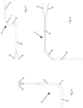
- the at least one armored tubular cartridge 2 comprises more than one stretch or portion; in which at least one first stretch 6 defines a straight longitudinal axis and at least one second stretch 7 defines a curvilinear axis.
- the armored tubular cartridge 2 comprises, or consists of, two straight stretches 6, 6' joined together by at least one curvilinear stretch 7, preferably by only one curvilinear stretch 7.
- the two stretches 6, 6' are perpendicular to each other.
- the armored tubular cartridge 2 comprises two straight stretches 6, 6' joined together by at least one curvilinear stretch 7, preferably by only one curvilinear stretch 7.
- a further straight stretch 6" is provided in sequence to the straight stretch 6'.
- the stretches 6, 6' are perpendicular to each other and, possibly, also the stretches 6', 6" are perpendicular to each other and, therefore, the stretches 6 and 6" are parallel to each other.
- a variant of this third embodiment can include the presence of a further curvilinear stretch between the straight stretch 6' and the straight stretch 6", said further curvilinear stretch having a radius of curvature opposite to the curvilinear stretch 7.
- Another variant of this third embodiment can instead include the presence of two curvilinear stretches, with opposite radius of curvature, between the straight stretch 6 and the straight stretch 6". In this latter case, the straight stretch 6' is not provided.
- the armored tubular cartridge 2 comprises at least two straight stretches 6, 6'; each stretch 6, 6' defining a respective straight longitudinal axis and in which the straight longitudinal axes define a broken line.
- straight stretches 6, 6', 6" are provided.
- the straight stretches 6 and 6" are perpendicular to each other, while the intermediate straight stretch 6' is inclined by an acute angle, preferably between 30° and 60°, for example 45°, with respect to one of the two stretches 6, 6".
- Figures 4, 5 and 6 do not show the block of aluminum 4 surrounding the armored tubular cartridge 2.
- each stretch 6, 6', 6" 7 comprises at least one PTC resistor 3 therein.
- each straight stretch 6, 6', 6" comprises a plurality of PTC resistors 3, preferably in ceramic material, connected in sequence to one another along the entire stretch and inserted between two heat sinks or electrodes 8 in aluminum, or alloys thereof, each aluminum heat sink or electrode 8 being connected to a respective electrical supply cable 9 which protrudes from one end of the armored tubular cartridge 2.
- a single PTC resistor 3 can be provided, substantially flat in shape and having a curvilinear axis, or a plurality of PTC resistors can be provided, substantially flat in shape and having a straight axis but a much shorter longitudinal extension with respect to the single PTC resistor with a curvilinear axis.
- the PTC resistors are arranged with the straight axes thereof incident to each other along the curvilinear stretch 7.
- the single PTC resistor or the plurality of PTC resistors are inserted between two heat sinks or electrodes 8 in aluminum, or alloys thereof, each aluminum heat sink or electrode 8 being connected to a respective electrical supply cable 9 which protrudes from one end of the armored tubular cartridge 2.
- the process comprises the following steps:
Landscapes
- Resistance Heating (AREA)
- Surface Heating Bodies (AREA)
- Air-Conditioning For Vehicles (AREA)
- Saccharide Compounds (AREA)
Claims (11)
- Elektrische Heizung (1), umfassend:- mindestens eine gepanzerte röhrenförmige Kartusche (2), die mindestens einen PTC-Widerstand (3) darin aufweist; und- einen Block aus Aluminium (4) oder Legierungen davon;dadurch gekennzeichnet, dassder Block aus Aluminium durch Druckguss um die mindestens eine gepanzerte röhrenförmige Kartusche (2) überformt ist;wobei eine Überzugsschicht aus Kunststoffmaterial (5) vorgesehen ist, die um den Block aus Aluminium (4) überformt ist.
- Elektrische Heizung (1) nach Anspruch 1, wobei die mindestens eine gepanzerte röhrenförmige Kartusche (2) nur eine gerade Längsachse X oder nur eine gekrümmte Längsachse definiert.
- Elektrische Heizung (1) nach Anspruch 1, wobei die mindestens eine gepanzerte röhrenförmige Kartusche (2) mehr als eine Erstreckung umfasst; wobei mindestens eine erste Erstreckung (6) eine gerade Längsachse definiert und mindestens eine zweite Erstreckung (7) eine gekrümmte Achse definiert.
- Elektrische Heizung (1) nach Anspruch 3, wobei mindestens zwei erste Erstreckungen (6, 6', 6"), vorzugsweise nur zwei erste Erstreckungen (6, 6'), vorgesehen sind, die durch mindestens eine zweite Erstreckung (7), vorzugsweise nur durch eine zweite Erstreckung (7), miteinander verbunden sind.
- Elektrische Heizung (1) nach Anspruch 1, wobei die mindestens eine gepanzerte röhrenförmige Kartusche (2) mindestens zwei Erstreckungen (6, 6') umfasst; wobei jede Erstreckung (6, 6') eine jeweilige gerade Längsachse definiert und die geraden Längsachsen eine unterbrochene Linie definieren.
- Elektrische Heizung (1) nach Anspruch 5, wobei drei Erstreckungen (6, 6', 6") vorgesehen sind.
- Elektrische Heizung (1) nach einem der vorhergehenden Ansprüche, wobei eine Vielzahl von PTC-Widerständen (3), vorzugsweise aus keramischem Material, vorgesehen sind, die entlang der gesamten gepanzerten röhrenförmigen Kartusche (2) hintereinander verbunden sind.
- Elektrische Heizung (1) nach einem der vorhergehenden Ansprüche, wobei der mindestens eine PTC-Widerstand (3) zwischen zwei Kühlkörpern oder Elektroden aus Aluminium (8) oder Legierungen davon eingefügt ist, wobei jeder Aluminium-Kühlkörper oder -Elektrode (8) mit einem entsprechenden elektrischen Versorgungskabel (9) verbunden ist, das aus einem Ende der mindestens einen gepanzerten röhrenförmigen Kartusche (2) herausragt.
- Elektrische Heizung (1) nach Anspruch 8, wobei die durch die Aluminium-Kühlkörper oder -Elektroden (8) und den mindestens einen PTC-Widerstand (3) definierte Anordnung von einer Schicht aus isolierendem Material (10), vorzugsweise pulverförmigem Magnesiumoxid oder Polyimid, umgeben ist, die außen durch eine Metallumhüllung (11), vorzugsweise aus Stahl, begrenzt ist.
- Elektrische Heizung (1) nach Anspruch 9, wobei der Block aus Aluminium (4) oder Legierungen davon durch Druckguss um die Metallumhüllung (2) herumgeformt ist.
- Verfahren zur Herstellung einer elektrischen Heizung (1) nach einem der vorhergehenden Ansprüche, wobei das Verfahren die folgenden Schritte umfasst:- Bereitstellen mindestens einer gepanzerten röhrenförmigen Kartusche (2), die mindestens einen PTC-Widerstand (3) darin aufweist;- Überformen der mindestens einen gepanzerten röhrenförmigen Kartusche (2) mit einem Block aus Aluminium (4) oder Legierungen davon durch Druckguss;- Überformen des Aluminiumblocks (4) mit Kunststoffmaterial, um eine Überzugsschicht (5) zu erzeugen.
Applications Claiming Priority (2)
| Application Number | Priority Date | Filing Date | Title |
|---|---|---|---|
| IT102019000012903A IT201900012903A1 (it) | 2019-07-25 | 2019-07-25 | Riscaldatore elettrico |
| PCT/IB2020/057058 WO2021014432A1 (en) | 2019-07-25 | 2020-07-27 | Electric heater |
Publications (2)
| Publication Number | Publication Date |
|---|---|
| EP4005342A1 EP4005342A1 (de) | 2022-06-01 |
| EP4005342B1 true EP4005342B1 (de) | 2023-08-30 |
Family
ID=68733496
Family Applications (1)
| Application Number | Title | Priority Date | Filing Date |
|---|---|---|---|
| EP20764149.9A Active EP4005342B1 (de) | 2019-07-25 | 2020-07-27 | Elektrischer heizer |
Country Status (9)
| Country | Link |
|---|---|
| US (1) | US20220287157A1 (de) |
| EP (1) | EP4005342B1 (de) |
| JP (1) | JP7607628B2 (de) |
| KR (1) | KR20220066883A (de) |
| CN (1) | CN114731741A (de) |
| CA (1) | CA3149100A1 (de) |
| ES (1) | ES2965815T3 (de) |
| IT (1) | IT201900012903A1 (de) |
| WO (1) | WO2021014432A1 (de) |
Families Citing this family (2)
| Publication number | Priority date | Publication date | Assignee | Title |
|---|---|---|---|---|
| SK9745Y1 (sk) | 2022-08-15 | 2023-05-17 | Protherm Production S.R.O. | Modulárny PTC elektrický ohrievač |
| SK10260Y1 (sk) * | 2024-06-11 | 2025-01-29 | Protherm Production S.R.O. | PTC elektrický prietokový ohrievač s keramickou izoláciou |
Family Cites Families (14)
| Publication number | Priority date | Publication date | Assignee | Title |
|---|---|---|---|---|
| EP0055350A3 (de) * | 1980-12-29 | 1982-09-08 | Steinel GmbH & Co. KG | Vorrichtung zur Verflüssigung eines schmelzbaren Klebers |
| DE3049343C2 (de) * | 1980-12-29 | 1983-06-09 | Steinel GmbH & Co KG, 4836 Herzebrock | Vorrichtung zur Verflüssigung eines schmelzbaren Klebers |
| FR2579854A1 (fr) * | 1985-03-29 | 1986-10-03 | Etirex | Resistance electrique blindee a enroulements coaxiaux |
| US4972067A (en) * | 1989-06-21 | 1990-11-20 | Process Technology Inc. | PTC heater assembly and a method of manufacturing the heater assembly |
| JPH0778675A (ja) * | 1993-09-09 | 1995-03-20 | Kawai Denki Seisakusho:Kk | カートリッジヒータ |
| GB9718109D0 (en) * | 1997-08-27 | 1997-10-29 | Strix Ltd | Electric heaters |
| AU3929299A (en) * | 1999-04-28 | 2000-11-17 | I.R.C.A. S.P.A. - Industria Resistenze Corazzate E Affini | Resistance element for defrosting evaporators in refrigeration units |
| JP2001017372A (ja) * | 1999-07-05 | 2001-01-23 | Hitachi Ltd | 食器洗い乾燥機 |
| US20070251938A1 (en) * | 2006-04-26 | 2007-11-01 | Watlow Electric Manufacturing Company | Ceramic heater and method of securing a thermocouple thereto |
| WO2012171072A1 (en) * | 2011-06-16 | 2012-12-20 | Resmed Limited | Humifier and layered heating element |
| ITUB20152625A1 (it) * | 2015-07-30 | 2017-01-30 | Irca Spa | Resistenza corazzata e relativo processo di produzione |
| EP3348931B1 (de) * | 2015-09-09 | 2024-07-17 | Marelli Cabin Comfort Japan Corporation | Fluidheizvorrichtung und herstellungsverfahren dafür |
| US20190072309A1 (en) * | 2017-09-06 | 2019-03-07 | Bsh-Hausgeraete Gmbh | Ice maker with a heater and an ice tray made of heat-conductive plastic, and household cooling appliance |
| IT201800007346A1 (it) * | 2018-07-19 | 2020-01-19 | Riscaldatore elettrico per serbatoio |
-
2019
- 2019-07-25 IT IT102019000012903A patent/IT201900012903A1/it unknown
-
2020
- 2020-07-27 CN CN202080053391.7A patent/CN114731741A/zh active Pending
- 2020-07-27 CA CA3149100A patent/CA3149100A1/en active Pending
- 2020-07-27 WO PCT/IB2020/057058 patent/WO2021014432A1/en not_active Ceased
- 2020-07-27 EP EP20764149.9A patent/EP4005342B1/de active Active
- 2020-07-27 ES ES20764149T patent/ES2965815T3/es active Active
- 2020-07-27 KR KR1020227004530A patent/KR20220066883A/ko not_active Ceased
- 2020-07-27 US US17/629,393 patent/US20220287157A1/en active Pending
- 2020-07-27 JP JP2022503821A patent/JP7607628B2/ja active Active
Also Published As
| Publication number | Publication date |
|---|---|
| ES2965815T3 (es) | 2024-04-17 |
| CN114731741A (zh) | 2022-07-08 |
| JP7607628B2 (ja) | 2024-12-27 |
| CA3149100A1 (en) | 2021-01-28 |
| WO2021014432A1 (en) | 2021-01-28 |
| KR20220066883A (ko) | 2022-05-24 |
| JP2022546917A (ja) | 2022-11-10 |
| IT201900012903A1 (it) | 2021-01-25 |
| US20220287157A1 (en) | 2022-09-08 |
| EP4005342A1 (de) | 2022-06-01 |
Similar Documents
| Publication | Publication Date | Title |
|---|---|---|
| US8731386B2 (en) | Electric heating device for heating fluids | |
| KR100867026B1 (ko) | 가열 러너 노즐 및 다중 노즐 배열체 | |
| EP1795048B1 (de) | Anpassbares geschichtetes heizsystem | |
| EP3424264B1 (de) | Heizungsbündel für anpassungsfähige steuerung | |
| CA1149855A (en) | Arrangement for the prewarming of heating oil | |
| EP2324682B1 (de) | Heizkabel | |
| US20110297666A1 (en) | Heating Apparatus and Method for Producing the Heating Apparatus | |
| EP2865963B1 (de) | Elektrische Heizungsvorrichtung | |
| CN109693514B (zh) | 用于机动车辆的电加热器 | |
| US20220287157A1 (en) | Electric heater | |
| EP4325137A1 (de) | Modularer elektrischer ptc-heizer | |
| EP4290155B1 (de) | Elektrischer ptc-heizer | |
| EP1829425B1 (de) | Steuerung eines heizungskabels | |
| KR20180112836A (ko) | 열교환기, 특히 물-공기 열교환기 또는 오일-물 열교환기 | |
| EP3068984B1 (de) | Kontakterhitzer | |
| EP0287898B1 (de) | Flexibles gestricktes Thermistorheizkabel | |
| KR20180112835A (ko) | 특히 차량 내연 기관의 오일-물 열교환기 | |
| EP1537761B1 (de) | Elektrisches heizkabel | |
| EP3203162B1 (de) | Heizstruktur für heisse luftverteiler | |
| EP3401617A1 (de) | Elektrische heizeinrichtung | |
| US20190074112A1 (en) | Sheath heater | |
| EP4070625B1 (de) | Elektrischer heizer zum heizen eine substanz in einem kraftfahrzeug | |
| KR20170063476A (ko) | 면상발열체를 이용한 배관 히팅 시스템 | |
| EP2438364B1 (de) | Elektrisches heizgerät | |
| CA2804160C (en) | A low resistance electric heating system |
Legal Events
| Date | Code | Title | Description |
|---|---|---|---|
| STAA | Information on the status of an ep patent application or granted ep patent |
Free format text: STATUS: UNKNOWN |
|
| STAA | Information on the status of an ep patent application or granted ep patent |
Free format text: STATUS: THE INTERNATIONAL PUBLICATION HAS BEEN MADE |
|
| PUAI | Public reference made under article 153(3) epc to a published international application that has entered the european phase |
Free format text: ORIGINAL CODE: 0009012 |
|
| STAA | Information on the status of an ep patent application or granted ep patent |
Free format text: STATUS: REQUEST FOR EXAMINATION WAS MADE |
|
| 17P | Request for examination filed |
Effective date: 20220224 |
|
| AK | Designated contracting states |
Kind code of ref document: A1 Designated state(s): AL AT BE BG CH CY CZ DE DK EE ES FI FR GB GR HR HU IE IS IT LI LT LU LV MC MK MT NL NO PL PT RO RS SE SI SK SM TR |
|
| DAV | Request for validation of the european patent (deleted) | ||
| DAX | Request for extension of the european patent (deleted) | ||
| GRAP | Despatch of communication of intention to grant a patent |
Free format text: ORIGINAL CODE: EPIDOSNIGR1 |
|
| STAA | Information on the status of an ep patent application or granted ep patent |
Free format text: STATUS: GRANT OF PATENT IS INTENDED |
|
| INTG | Intention to grant announced |
Effective date: 20230323 |
|
| P01 | Opt-out of the competence of the unified patent court (upc) registered |
Effective date: 20230525 |
|
| GRAS | Grant fee paid |
Free format text: ORIGINAL CODE: EPIDOSNIGR3 |
|
| GRAA | (expected) grant |
Free format text: ORIGINAL CODE: 0009210 |
|
| STAA | Information on the status of an ep patent application or granted ep patent |
Free format text: STATUS: THE PATENT HAS BEEN GRANTED |
|
| AK | Designated contracting states |
Kind code of ref document: B1 Designated state(s): AL AT BE BG CH CY CZ DE DK EE ES FI FR GB GR HR HU IE IS IT LI LT LU LV MC MK MT NL NO PL PT RO RS SE SI SK SM TR |
|
| REG | Reference to a national code |
Ref country code: GB Ref legal event code: FG4D |
|
| REG | Reference to a national code |
Ref country code: CH Ref legal event code: EP |
|
| REG | Reference to a national code |
Ref country code: DE Ref legal event code: R096 Ref document number: 602020016848 Country of ref document: DE |
|
| REG | Reference to a national code |
Ref country code: IE Ref legal event code: FG4D |
|
| REG | Reference to a national code |
Ref country code: LT Ref legal event code: MG9D |
|
| REG | Reference to a national code |
Ref country code: NL Ref legal event code: MP Effective date: 20230830 |
|
| REG | Reference to a national code |
Ref country code: AT Ref legal event code: MK05 Ref document number: 1607139 Country of ref document: AT Kind code of ref document: T Effective date: 20230830 |
|
| PG25 | Lapsed in a contracting state [announced via postgrant information from national office to epo] |
Ref country code: GR Free format text: LAPSE BECAUSE OF FAILURE TO SUBMIT A TRANSLATION OF THE DESCRIPTION OR TO PAY THE FEE WITHIN THE PRESCRIBED TIME-LIMIT Effective date: 20231201 |
|
| PG25 | Lapsed in a contracting state [announced via postgrant information from national office to epo] |
Ref country code: IS Free format text: LAPSE BECAUSE OF FAILURE TO SUBMIT A TRANSLATION OF THE DESCRIPTION OR TO PAY THE FEE WITHIN THE PRESCRIBED TIME-LIMIT Effective date: 20231230 |
|
| PG25 | Lapsed in a contracting state [announced via postgrant information from national office to epo] |
Ref country code: SE Free format text: LAPSE BECAUSE OF FAILURE TO SUBMIT A TRANSLATION OF THE DESCRIPTION OR TO PAY THE FEE WITHIN THE PRESCRIBED TIME-LIMIT Effective date: 20230830 Ref country code: RS Free format text: LAPSE BECAUSE OF FAILURE TO SUBMIT A TRANSLATION OF THE DESCRIPTION OR TO PAY THE FEE WITHIN THE PRESCRIBED TIME-LIMIT Effective date: 20230830 Ref country code: NO Free format text: LAPSE BECAUSE OF FAILURE TO SUBMIT A TRANSLATION OF THE DESCRIPTION OR TO PAY THE FEE WITHIN THE PRESCRIBED TIME-LIMIT Effective date: 20231130 Ref country code: LV Free format text: LAPSE BECAUSE OF FAILURE TO SUBMIT A TRANSLATION OF THE DESCRIPTION OR TO PAY THE FEE WITHIN THE PRESCRIBED TIME-LIMIT Effective date: 20230830 Ref country code: LT Free format text: LAPSE BECAUSE OF FAILURE TO SUBMIT A TRANSLATION OF THE DESCRIPTION OR TO PAY THE FEE WITHIN THE PRESCRIBED TIME-LIMIT Effective date: 20230830 Ref country code: IS Free format text: LAPSE BECAUSE OF FAILURE TO SUBMIT A TRANSLATION OF THE DESCRIPTION OR TO PAY THE FEE WITHIN THE PRESCRIBED TIME-LIMIT Effective date: 20231230 Ref country code: HR Free format text: LAPSE BECAUSE OF FAILURE TO SUBMIT A TRANSLATION OF THE DESCRIPTION OR TO PAY THE FEE WITHIN THE PRESCRIBED TIME-LIMIT Effective date: 20230830 Ref country code: GR Free format text: LAPSE BECAUSE OF FAILURE TO SUBMIT A TRANSLATION OF THE DESCRIPTION OR TO PAY THE FEE WITHIN THE PRESCRIBED TIME-LIMIT Effective date: 20231201 Ref country code: FI Free format text: LAPSE BECAUSE OF FAILURE TO SUBMIT A TRANSLATION OF THE DESCRIPTION OR TO PAY THE FEE WITHIN THE PRESCRIBED TIME-LIMIT Effective date: 20230830 Ref country code: AT Free format text: LAPSE BECAUSE OF FAILURE TO SUBMIT A TRANSLATION OF THE DESCRIPTION OR TO PAY THE FEE WITHIN THE PRESCRIBED TIME-LIMIT Effective date: 20230830 |
|
| PG25 | Lapsed in a contracting state [announced via postgrant information from national office to epo] |
Ref country code: PL Free format text: LAPSE BECAUSE OF FAILURE TO SUBMIT A TRANSLATION OF THE DESCRIPTION OR TO PAY THE FEE WITHIN THE PRESCRIBED TIME-LIMIT Effective date: 20230830 Ref country code: NL Free format text: LAPSE BECAUSE OF FAILURE TO SUBMIT A TRANSLATION OF THE DESCRIPTION OR TO PAY THE FEE WITHIN THE PRESCRIBED TIME-LIMIT Effective date: 20230830 |
|
| REG | Reference to a national code |
Ref country code: ES Ref legal event code: FG2A Ref document number: 2965815 Country of ref document: ES Kind code of ref document: T3 Effective date: 20240417 |
|
| PG25 | Lapsed in a contracting state [announced via postgrant information from national office to epo] |
Ref country code: SM Free format text: LAPSE BECAUSE OF FAILURE TO SUBMIT A TRANSLATION OF THE DESCRIPTION OR TO PAY THE FEE WITHIN THE PRESCRIBED TIME-LIMIT Effective date: 20230830 Ref country code: RO Free format text: LAPSE BECAUSE OF FAILURE TO SUBMIT A TRANSLATION OF THE DESCRIPTION OR TO PAY THE FEE WITHIN THE PRESCRIBED TIME-LIMIT Effective date: 20230830 Ref country code: EE Free format text: LAPSE BECAUSE OF FAILURE TO SUBMIT A TRANSLATION OF THE DESCRIPTION OR TO PAY THE FEE WITHIN THE PRESCRIBED TIME-LIMIT Effective date: 20230830 Ref country code: DK Free format text: LAPSE BECAUSE OF FAILURE TO SUBMIT A TRANSLATION OF THE DESCRIPTION OR TO PAY THE FEE WITHIN THE PRESCRIBED TIME-LIMIT Effective date: 20230830 Ref country code: CZ Free format text: LAPSE BECAUSE OF FAILURE TO SUBMIT A TRANSLATION OF THE DESCRIPTION OR TO PAY THE FEE WITHIN THE PRESCRIBED TIME-LIMIT Effective date: 20230830 Ref country code: PT Free format text: LAPSE BECAUSE OF FAILURE TO SUBMIT A TRANSLATION OF THE DESCRIPTION OR TO PAY THE FEE WITHIN THE PRESCRIBED TIME-LIMIT Effective date: 20240102 Ref country code: SK Free format text: LAPSE BECAUSE OF FAILURE TO SUBMIT A TRANSLATION OF THE DESCRIPTION OR TO PAY THE FEE WITHIN THE PRESCRIBED TIME-LIMIT Effective date: 20230830 |
|
| REG | Reference to a national code |
Ref country code: DE Ref legal event code: R097 Ref document number: 602020016848 Country of ref document: DE |
|
| PLBE | No opposition filed within time limit |
Free format text: ORIGINAL CODE: 0009261 |
|
| STAA | Information on the status of an ep patent application or granted ep patent |
Free format text: STATUS: NO OPPOSITION FILED WITHIN TIME LIMIT |
|
| PG25 | Lapsed in a contracting state [announced via postgrant information from national office to epo] |
Ref country code: SI Free format text: LAPSE BECAUSE OF FAILURE TO SUBMIT A TRANSLATION OF THE DESCRIPTION OR TO PAY THE FEE WITHIN THE PRESCRIBED TIME-LIMIT Effective date: 20230830 |
|
| 26N | No opposition filed |
Effective date: 20240603 |
|
| PG25 | Lapsed in a contracting state [announced via postgrant information from national office to epo] |
Ref country code: BG Free format text: LAPSE BECAUSE OF FAILURE TO SUBMIT A TRANSLATION OF THE DESCRIPTION OR TO PAY THE FEE WITHIN THE PRESCRIBED TIME-LIMIT Effective date: 20230830 |
|
| PG25 | Lapsed in a contracting state [announced via postgrant information from national office to epo] |
Ref country code: BG Free format text: LAPSE BECAUSE OF FAILURE TO SUBMIT A TRANSLATION OF THE DESCRIPTION OR TO PAY THE FEE WITHIN THE PRESCRIBED TIME-LIMIT Effective date: 20230830 |
|
| PG25 | Lapsed in a contracting state [announced via postgrant information from national office to epo] |
Ref country code: MC Free format text: LAPSE BECAUSE OF FAILURE TO SUBMIT A TRANSLATION OF THE DESCRIPTION OR TO PAY THE FEE WITHIN THE PRESCRIBED TIME-LIMIT Effective date: 20230830 |
|
| REG | Reference to a national code |
Ref country code: CH Ref legal event code: PL |
|
| PG25 | Lapsed in a contracting state [announced via postgrant information from national office to epo] |
Ref country code: LU Free format text: LAPSE BECAUSE OF NON-PAYMENT OF DUE FEES Effective date: 20240727 |
|
| PG25 | Lapsed in a contracting state [announced via postgrant information from national office to epo] |
Ref country code: LU Free format text: LAPSE BECAUSE OF NON-PAYMENT OF DUE FEES Effective date: 20240727 |
|
| PG25 | Lapsed in a contracting state [announced via postgrant information from national office to epo] |
Ref country code: BE Free format text: LAPSE BECAUSE OF NON-PAYMENT OF DUE FEES Effective date: 20240731 Ref country code: CH Free format text: LAPSE BECAUSE OF NON-PAYMENT OF DUE FEES Effective date: 20240731 |
|
| REG | Reference to a national code |
Ref country code: BE Ref legal event code: MM Effective date: 20240731 |
|
| PG25 | Lapsed in a contracting state [announced via postgrant information from national office to epo] |
Ref country code: IE Free format text: LAPSE BECAUSE OF NON-PAYMENT OF DUE FEES Effective date: 20240727 |
|
| PGFP | Annual fee paid to national office [announced via postgrant information from national office to epo] |
Ref country code: ES Payment date: 20250827 Year of fee payment: 6 |
|
| PGFP | Annual fee paid to national office [announced via postgrant information from national office to epo] |
Ref country code: DE Payment date: 20250722 Year of fee payment: 6 |
|
| PGFP | Annual fee paid to national office [announced via postgrant information from national office to epo] |
Ref country code: IT Payment date: 20250730 Year of fee payment: 6 |
|
| PGFP | Annual fee paid to national office [announced via postgrant information from national office to epo] |
Ref country code: GB Payment date: 20250722 Year of fee payment: 6 |
|
| PGFP | Annual fee paid to national office [announced via postgrant information from national office to epo] |
Ref country code: FR Payment date: 20250725 Year of fee payment: 6 |
|
| PG25 | Lapsed in a contracting state [announced via postgrant information from national office to epo] |
Ref country code: CY Free format text: LAPSE BECAUSE OF FAILURE TO SUBMIT A TRANSLATION OF THE DESCRIPTION OR TO PAY THE FEE WITHIN THE PRESCRIBED TIME-LIMIT; INVALID AB INITIO Effective date: 20200727 |
|
| PG25 | Lapsed in a contracting state [announced via postgrant information from national office to epo] |
Ref country code: HU Free format text: LAPSE BECAUSE OF FAILURE TO SUBMIT A TRANSLATION OF THE DESCRIPTION OR TO PAY THE FEE WITHIN THE PRESCRIBED TIME-LIMIT; INVALID AB INITIO Effective date: 20200727 |