EP4004569B1 - Verfahren sowie vorrichtung zur prüfung der isolation eines elektrischen bauteils, insbesondere eines hv-kabelsatzes - Google Patents
Verfahren sowie vorrichtung zur prüfung der isolation eines elektrischen bauteils, insbesondere eines hv-kabelsatzes Download PDFInfo
- Publication number
- EP4004569B1 EP4004569B1 EP20734345.0A EP20734345A EP4004569B1 EP 4004569 B1 EP4004569 B1 EP 4004569B1 EP 20734345 A EP20734345 A EP 20734345A EP 4004569 B1 EP4004569 B1 EP 4004569B1
- Authority
- EP
- European Patent Office
- Prior art keywords
- test
- sheath
- insulation
- component
- wall
- Prior art date
- Legal status (The legal status is an assumption and is not a legal conclusion. Google has not performed a legal analysis and makes no representation as to the accuracy of the status listed.)
- Active
Links
- 238000012360 testing method Methods 0.000 title claims description 210
- 238000009413 insulation Methods 0.000 title claims description 57
- 238000000034 method Methods 0.000 title claims description 27
- 239000004020 conductor Substances 0.000 claims description 15
- 239000002985 plastic film Substances 0.000 claims description 13
- 229920006255 plastic film Polymers 0.000 claims description 13
- 238000010998 test method Methods 0.000 claims description 6
- 238000004806 packaging method and process Methods 0.000 claims description 5
- 239000011248 coating agent Substances 0.000 claims description 4
- 238000000576 coating method Methods 0.000 claims description 4
- 230000002950 deficient Effects 0.000 claims description 4
- 239000004744 fabric Substances 0.000 claims description 2
- 239000000463 material Substances 0.000 claims description 2
- 239000010410 layer Substances 0.000 description 20
- 238000005259 measurement Methods 0.000 description 7
- 238000007789 sealing Methods 0.000 description 7
- 239000007789 gas Substances 0.000 description 5
- 239000000853 adhesive Substances 0.000 description 4
- 230000001070 adhesive effect Effects 0.000 description 4
- 150000003839 salts Chemical class 0.000 description 4
- 239000004033 plastic Substances 0.000 description 3
- XLYOFNOQVPJJNP-UHFFFAOYSA-N water Substances O XLYOFNOQVPJJNP-UHFFFAOYSA-N 0.000 description 3
- XKRFYHLGVUSROY-UHFFFAOYSA-N Argon Chemical compound [Ar] XKRFYHLGVUSROY-UHFFFAOYSA-N 0.000 description 2
- 238000004519 manufacturing process Methods 0.000 description 2
- 230000013011 mating Effects 0.000 description 2
- 239000002356 single layer Substances 0.000 description 2
- 229910052786 argon Inorganic materials 0.000 description 1
- 230000000712 assembly Effects 0.000 description 1
- 238000000429 assembly Methods 0.000 description 1
- 238000009954 braiding Methods 0.000 description 1
- 230000015556 catabolic process Effects 0.000 description 1
- 238000010276 construction Methods 0.000 description 1
- 230000007547 defect Effects 0.000 description 1
- 230000009977 dual effect Effects 0.000 description 1
- 238000010292 electrical insulation Methods 0.000 description 1
- 238000009429 electrical wiring Methods 0.000 description 1
- 239000000835 fiber Substances 0.000 description 1
- 239000011888 foil Substances 0.000 description 1
- 238000011990 functional testing Methods 0.000 description 1
- 238000002955 isolation Methods 0.000 description 1
- 239000007788 liquid Substances 0.000 description 1
- 238000000691 measurement method Methods 0.000 description 1
- 239000012528 membrane Substances 0.000 description 1
- 239000002184 metal Substances 0.000 description 1
- 230000001681 protective effect Effects 0.000 description 1
- 230000002787 reinforcement Effects 0.000 description 1
- 239000003566 sealing material Substances 0.000 description 1
- 238000010561 standard procedure Methods 0.000 description 1
- 239000004753 textile Substances 0.000 description 1
Images
Classifications
-
- G—PHYSICS
- G01—MEASURING; TESTING
- G01R—MEASURING ELECTRIC VARIABLES; MEASURING MAGNETIC VARIABLES
- G01R31/00—Arrangements for testing electric properties; Arrangements for locating electric faults; Arrangements for electrical testing characterised by what is being tested not provided for elsewhere
- G01R31/12—Testing dielectric strength or breakdown voltage ; Testing or monitoring effectiveness or level of insulation, e.g. of a cable or of an apparatus, for example using partial discharge measurements; Electrostatic testing
- G01R31/16—Construction of testing vessels; Electrodes therefor
-
- G—PHYSICS
- G01—MEASURING; TESTING
- G01R—MEASURING ELECTRIC VARIABLES; MEASURING MAGNETIC VARIABLES
- G01R31/00—Arrangements for testing electric properties; Arrangements for locating electric faults; Arrangements for electrical testing characterised by what is being tested not provided for elsewhere
- G01R31/12—Testing dielectric strength or breakdown voltage ; Testing or monitoring effectiveness or level of insulation, e.g. of a cable or of an apparatus, for example using partial discharge measurements; Electrostatic testing
- G01R31/1227—Testing dielectric strength or breakdown voltage ; Testing or monitoring effectiveness or level of insulation, e.g. of a cable or of an apparatus, for example using partial discharge measurements; Electrostatic testing of components, parts or materials
- G01R31/1263—Testing dielectric strength or breakdown voltage ; Testing or monitoring effectiveness or level of insulation, e.g. of a cable or of an apparatus, for example using partial discharge measurements; Electrostatic testing of components, parts or materials of solid or fluid materials, e.g. insulation films, bulk material; of semiconductors or LV electronic components or parts; of cable, line or wire insulation
- G01R31/1272—Testing dielectric strength or breakdown voltage ; Testing or monitoring effectiveness or level of insulation, e.g. of a cable or of an apparatus, for example using partial discharge measurements; Electrostatic testing of components, parts or materials of solid or fluid materials, e.g. insulation films, bulk material; of semiconductors or LV electronic components or parts; of cable, line or wire insulation of cable, line or wire insulation, e.g. using partial discharge measurements
Definitions
- the invention relates to a method and a device for testing the insulation of an electrical component, in particular a cable, especially a cable set and in particular a high-voltage cable (HV cable) or a high-voltage cable set (HV cable set).
- a cable especially a cable set and in particular a high-voltage cable (HV cable) or a high-voltage cable set (HV cable set).
- HV cable high-voltage cable
- HV cable set high-voltage cable set
- Cable assemblies generally consist of several interconnected components.
- cable harnesses for example, several individual lines or individual cables are typically combined and typically form a branched structure.
- the individual lines or cables are pre-assembled, ie they already have contact elements or plugs at the ends.
- Individual cables can also be connected to one another within the cable set, for example via distributors or connectors, etc.
- a functional test is generally carried out at the end of a cable harness production. Among other things, the integrity of the insulation of the cable set is checked during this test. This test, also known as the "insulation test", ensures, for example, that no live parts of the conductor have penetrated an insulating jacket and/or that the integrity of the insulation is ensured. In the case of shielded HV cables, an insulation resistance of the insulation can be measured against the shield attached to the inner conductor.
- From the DE 33 09 658 A1 shows a device for optically testing the dielectric strength of an electrical insulation, in which a plate with a lateral sealing element is placed on the insulation to be tested and a test space is also enclosed between the plate and the insulation to be tested, which is evacuated, for example, or filled with a test gas is filled.
- From the DE 28 016 49 A1 shows a test device in which a cable to be tested is placed in a tube surrounding the cable and also filled with a test gas.
- From the DE 10 2016 116 695 A1 discloses a method of inspecting a wire harness by putting a cuff on a wire in an inspecting section to inspect whether a specific test line of the wire harness is in the inspecting section.
- test clamp for checking a cable set can be found.
- the test tongs have two arms that are attached to one another and grips the cable set to be tested. There is a test room above the front seals formed, in which a test medium is introduced. To test the cable, the test clamp is successively guided along the cable.
- the invention is based on the object of specifying a method and a device for testing the insulation of an electrical component, in particular a HV cable set.
- the object directed to the method is solved by a method for testing the insulation of an electrical component with the features of claim 1.
- the electrical component is in particular a cable, specifically a cable set, in particular a high-voltage cable (HV cable), specifically a high-voltage cable set (HV cable set).
- HV cable high-voltage cable
- HV cable set high-voltage cable set
- the method described below and the device are also suitable for testing other electrical components, for example an electrical device in which electrical components are surrounded by an insulating housing.
- the electrical component generally has an electrical core which is surrounded by the insulation to be tested.
- the insulation is, for example, a cable jacket and/or an insulating housing.
- a voltage is applied to the electrical core.
- the electrical core is in particular a conductor which is surrounded by a cable sheath as insulation.
- the electrical core is formed by the multiple conductors, each of which is surrounded by a conductor insulation (core sheath) and each forms a core.
- the multi-core cable is surrounded by a common cable sheath, which is at least part of the insulation to be tested.
- test case in which the component to be tested is placed during the test.
- the test envelope has a wall made of a flexible and electrically conductive material, the flexibility of the test envelope being such that it lies flat against the insulation so that it accommodates an outer contour of the insulation and simulates it.
- a test voltage is applied to the electrical core and a suitable measurement is used to determine whether the insulation meets the quality requirements or whether the insulation is defective.
- the test sleeve is therefore used in the manner of an electrode.
- a check is made as to whether a leakage current is flowing away via the measuring sleeve and, in particular, how high this leakage current is, in order to decide whether it exceeds a critical value.
- the potential applied to the measuring sleeve is measured, for example with respect to a reference potential. In general, therefore, an electrical property of the test envelope is measured and, based on the measurement result, it is determined whether the insulation meets the quality requirements or is defective.
- Another advantage of the measuring method with this flexible test sleeve is that no additional media such as salt water or special test gases are introduced, which are then arranged in a space between the test sleeve, which serves as an electrode, and the insulation. Therefore, additional test media such as test gas or test liquid are not used.
- the test envelope lies directly and flat against the insulation.
- the test envelope is a test bag that holds the component to be tested.
- a “test pocket” is generally understood to mean that it has two opposite envelope surfaces which—at least when the test method is being carried out or alternatively permanently—are connected to one another on at least three edge sides.
- the edge sides can preferably be closed, in particular reversibly, by means of a closure element.
- the test bag therefore defines a closed test space, which only has an opening towards one edge side. This can preferably also be closed during the testing process.
- the component lies in the test pocket, preferably completely.
- the test pocket therefore forms a closed test space, which has the opening, which in particular can be closed, on only one side.
- At least one end of the component preferably several ends of the component, is brought out of this opening for connection to a voltage supply, specifically for connection to the test voltage.
- the led-out ends are specially formed by contact terminals.
- the component lies completely in the test case and the voltage connection is made via the opening using a connection element.
- the test envelope accommodates the component at least largely completely.
- “largely complete” is understood to mean that the component to be tested lies completely in the test envelope, with the exception of any connection areas of the component to be tested.
- the connection areas of the component, which are led out of the test envelope, are used to apply the test voltage.
- the ends that are pre-assembled with a plug, for example, are brought out, the rest of the cable set, i.e. for example at least 90% (of the entire cable length) is accommodated in the test case.
- the complete component to be tested, in particular the HV cable set is preferably in the test case, especially in the test bag.
- test method described below with the special test envelope can also be used for test situations in which the component is alternatively only partially, for example in sections, in the test envelope, which in turn can be designed as a test pocket.
- a cable set is understood to mean that a number of individual cables or lines are connected to one another to form a unit and typically form a branched structure.
- the individual cables are often connected to one another, for example via distributors or connectors, or are at least pre-assembled at the end with contact elements and/or plug elements.
- a high-voltage cable or cable set is understood to mean that the respective cable or cable set is designed for high voltages of in particular more than 250 volts, preferably more than 500 volts or even more than 1,000 volts and preferably up to a maximum of 1,500 to 2,000 volts is designed.
- the HV cables are typically designed to conduct high currents and accordingly have a large conductor cross section of, for example, several square millimeters (mm 2 ), for example more than 2.5 mm 2 .
- Such HV cable harnesses are used, for example, in the automotive industry, specifically for motor vehicles with an electric drive motor (electric vehicle or hybrid vehicle).
- the individual HV cable is typically a single-wire line, which is either provided with a shield as the outer conductor in the manner of a coaxial line, or in which there is no shield.
- the HV cable consists, for example, only of the conductor and the insulation surrounding it, which thus forms a core or cable sheath.
- the individual HV cable can also be a multi-core cable in which the individual cable cores are surrounded by a common insulating jacket as insulation.
- a negative pressure is generated in the test envelope with the component lying therein, compared to the pressure prevailing outside the test envelope.
- the test envelope ie its wall, nestles against the insulation and touches the insulation over a large area, in particular over the entire area.
- “Large area” means that more than 60%, preferably more than 80% and in particular more than 90% of the insulation is in contact with the test envelope. This means that only a small part of the surface of the insulation to be tested is not touched by the test envelope.
- low pressure is understood to mean a negative pressure of at least 150 hPa (150 mbar), preferably of at least 250 hPa.
- the negative pressure is preferably a maximum of 1000 hPa (1 bar) and specifically a maximum of 500 hPa.
- a negative pressure in the range of 200 hPa and 500 hPa is preferably set.
- the test envelope preferably has a suction connection, to which a suction line is connected in order to generate the negative pressure.
- the suction connection is, for example, a sleeve-like or bushing-like element, which is introduced into the wall in particular in a sealing manner and enables a flow path into the interior of the test casing.
- the socket typically consists of a material that is significantly stiffer than the wall, specifically plastic.
- the suction connection preferably has a closure valve that acts in particular automatically, such as a membrane closure, which prevents air from flowing in after the negative pressure has been generated.
- test envelope can also be closed airtight when the component is inserted.
- a closure element can be dispensed with, since when a negative pressure is applied, opposite wall areas of the test envelope are pulled together and are then possibly even self-sealing.
- one or more separate closure elements are preferably provided for the particularly airtight closure.
- the edge areas of the test case can be closed with a zip fastener or with adhesive or adhesive strips.
- This at least one closure element is in particular an integral part of the wall, ie firmly connected to it.
- necessary bushings for example for the bushing of the end areas of the cable harness to be tested, are expediently designed as airtight bushings.
- preferably half-shell-like reinforcements or sealing elements are integrated into the test envelope, for example, which are then placed around the cable section that has been passed through and enclose it in a sealing manner.
- fixing clamps etc. attached to the outside edge can be provided, which press the test sleeve against the partial area of the cable that has been passed through.
- the test envelope preferably has a measuring connection for connecting a measuring device, by means of which the electrical property is measured, in particular the test envelope is checked for an applied voltage.
- the measuring connection is, for example, a contact bolt, a contact socket or some other plug-in element.
- the component generally has at least one contact connection to which a voltage is applied when used as intended.
- a cable or a cable set is a contact element attached at the end, in particular a cable (set) plug.
- the cable set usually has a number of such cable set plugs.
- At least one or more such contact connections lie in the test case during the test. At least one connection end of the component to be tested is therefore in the test case. As a result, the insulation resistance of the connected contact element is checked at the same time during the test.
- connection element is preferably formed for this purpose, which is integrated into the test envelope and to which the component located inside the test envelope, specifically the cable harness, can be connected via the contact connection.
- the connection element is in particular a plug element, which therefore forms a mating plug for the cable harness plug. This eliminates the need to remove a section of the component to be tested from the test envelope.
- the component, especially the cable set is therefore connected to the integrated connection element inside the test case via a special plug connection.
- connection element itself is in turn preferably sealed and guided through the wall of the test envelope and has a connection contact on the outside, for example a plug-in contact for applying the test voltage.
- test voltage is generally applied via the contact connections of the component either directly or indirectly via the integrated connection element.
- the wall is generally a highly flexible, specifically film-like or also material-like covering. This has a low level of rigidity, so that it can easily adapt to the outer contour of the component to be tested, especially when the vacuum is applied.
- the wall has a wall thickness or thickness in the range of up to a maximum of 300 ⁇ m, preferably up to a maximum of 200 ⁇ m or up to a maximum of 100 ⁇ m.
- the wall has a film-like character, as is generally known, for example, in the packaging of food, specifically in the vacuum-tight packaging of food, for example by means of so-called freezer bags.
- the wall of the test envelope is preferably formed by a conductive plastic film or by a plastic film provided with a conductive coating.
- the wall has, in particular, a non-conductive film and a further, conductive layer.
- the conductive layer is formed, in particular, as a fabric or a mesh made of conductive fibers/threads, for example extremely fine wires.
- the conductive layer is oriented inwards towards the interior of the test envelope and is formed outwards by a film forming a gas-tight outer layer.
- the measuring connection is, for example, through a lead through the film Contact element realized, which is attached to the wall.
- this is a mechanically fastened element, for example a contact screw.
- the contact element is preferably passed airtight through the outer layer formed by the film. In principle, this principle of contacting with a contact element passed through the wall can also be used when using a conductive film or a film provided with a conductive coating.
- the test envelope is designed in the initial state as a single-layer film, for example, with the component to be tested first being placed on a first part, namely a lower part of the test envelope, and then a further part, hereinafter referred to as the upper part. placed over the component to be tested.
- a first part namely a lower part of the test envelope
- a further part hereinafter referred to as the upper part.
- the closure element or closure elements run in particular along the open edge sides, for example in a U-shape.
- the component to be tested remains in the test case after the test, and this is used as a protective cover or also as transport packaging, for example like a disposable item.
- the test sleeve fulfills a dual function, namely on the one hand for testing the cable set and as a transport packaging to an intended place of use.
- the test sleeve is alternatively used in the manner of a circulatory system for testing other components.
- the device has the test envelope and preferably also a measuring device and preferably also a vacuum pump.
- Figure 1A shows a test envelope 2, which in the illustrated embodiment has an unfolded film layer 6 with a first part, hereinafter referred to as the lower part 6A, and a further part, hereinafter referred to as the upper part 6B.
- the component in the form of a cable harness 4 rests on the lower part 6A.
- the two parts 6A, 6B are connected as indicated by the arrow in Figure 1A indicated, folded onto one another so that the upper part 6B rests on the lower part 6A with the cable harness 4 interposed.
- the two parts 6A, 6B together form a test pocket in which the cable set 4 lies.
- the test envelope 2 is already in the initial state as a test bag formed, which is only open on one side over which the component to be tested is inserted.
- the test envelope 2 has one or more closure elements 8 for the purpose of sealing in particular in an airtight manner. These preferably run along the edges and are designed, for example, in the manner of a closure strip, such as a zip closure or a pressure closure. In the case of pressure closures, two profile strips are pressed into one another to close the bag - as is known, for example, from the area of freezer bags.
- the closure element is designed as an adhesive or adhesive strip. This runs, for example, along the edge both along the upper part 6B and along the lower part 6A, as shown in FIG Figure 1A is shown.
- the film layer 6 is formed here, for example, by a plastic film 10 which either has an intrinsic conductivity or is provided with a conductive coating. Finally, there is also the possibility that a conductive layer is additionally arranged, as is shown in 4 is shown.
- the test envelope 2 also generally has a wall 12 which, in the exemplary embodiment of FIG Figure 1B is formed by the plastic film 10.
- the wall 12 seals off the test envelope 2 from the environment, in particular in an airtight manner. In this respect, the wall closes--in the case of a single cable set 4, when the test envelope 2 forms a test pocket--from an interior space of the test envelope to the environment.
- the wall 12 is gas-tight.
- test envelope 2 has a suction connection 14 and a measurement connection 16 .
- the suction connection 14 and the measuring connection 16 are each integrated components of the test envelope 2 and in particular are firmly connected to the wall 12 .
- the test envelope 2 also has lead-through elements 18, which are used in particular for the sealed, airtight passage of at least one element through a remaining (filling) opening in the test envelope 2, which is designed as a test bag serve.
- the element is in the embodiment of Figures 1A, 1B around a cable 20 of the cable harness 4.
- These lead-through elements 18 therefore also serve as closure elements 8. They are each formed, for example, in the manner of half-shells from a sealing material, for example plastic or rubber, and are each preferably firmly connected to the plastic film 10.
- Each pair of half-shells forms a lead-through element 18.
- the half-shells can be connected to one another, for example, by means of detachable connections, for example a clip connection or else a Velcro connection, etc.
- the end pieces of the cable set 4 led out of the test envelope 2 are therefore simply placed on the respective half-shells and then when the test envelope 2 is closed, the respective upper parts of the half-shells are connected to the lower parts, so that the respective cables 20 are led out airtight.
- the cable set 4 generally has a plurality of cables 20 which are each designed as HV cables.
- a respective cable 20 is designed as a single-core cable, which has only one central conductor 22 as an electrical core, which is directly surrounded by insulation 24, which therefore forms a core sheath (cf 4 ).
- the cable set 4 has two prefabricated electrical, first contact connections 26A on one connection side, which are preferably designed in the manner of plugs and in this respect form cable set plugs.
- the first contact terminals 26A are in the in Figures 1A, 1B situation shown outside of the test envelope 2 arranged.
- the cable set 4 has further electrical, second contact connections 26B, which are arranged inside the test case 2 .
- the cable set 4 has a branched structure with a plurality of cables 20 which are connected to one another via distributors 28 in the exemplary embodiment.
- the splitters 28 are 1-2 splitters, ie an incoming cable 20 is divided into two outgoing cables 20 .
- Two cables 4 are connected to the inner, second contact terminals 26B.
- In these second Contact connections 26B are in each case (plug) contact elements, so these are in particular two-pole contact connections 26B.
- the outer, first contact connections 26A are preferably single-pole contact connections 26A which, during operation, are connected to a positive or negative pole of a supply voltage, for example a battery.
- the two contact elements of the second contact connections 26 B arranged on the inside are preferably electrically connected to one another.
- the first contact terminals 26A of the cable set 4 are led out through the bushings 18 to the outside.
- the rest of the cable set 4, in particular also the second contact connections 26B, are sealed airtight in the test envelope 2 for the subsequent test. All in all, the cable set 4 lies almost completely in the test envelope 2 . This means that at least 90% of the total length of the individual cable strands of the cable set 4 is accommodated in the test envelope 2 .
- at least part of the contact connections 26B attached to the ends of the individual cables 20 is also accommodated by the test envelope 2 .
- the cable harness 4 is completely accommodated by the test case 2, ie all contact connections 26A, 26B are inside the test case 2.
- the cable set 4 therefore defines a total of an electrical component to be checked, which has an electrical core which is formed by the individual conductors 22 of the individual cables 20 and also by the contact elements located in the contact terminals 26B, 26A.
- the insulation 24 of this cable set 4 is formed on the one hand by the wire sheaths of the individual cables 20 and also by the individual insulating housings of the other components, such as the insulating housings of the distributors and the contact connections 26B.
- the procedure for checking the insulation 24 proceeds as follows: First, the cable set 4 is placed in the test case 2 designed as a test bag, ie the cable set 4 is accommodated at least almost completely or completely inside the test case 2 . This is preferably hermetically sealed. The air remaining inside the test envelope 2 is then sucked out via the suction connection 14, for example with the aid of a vacuum pump 30, and a negative pressure is generated. Due to the flexibility of the wall 12 and in general of the plastic film 10, the wall 12 nestles flat and following the outer contour of the cable set 4 to this outer contour. Here, a negative pressure is generated compared to the pressure prevailing in the environment of, for example, 300 to 800 hPa.
- a test voltage U1 is preferably applied to one of the two outer second contact connections 26B using a test or measuring device 32, which test voltage U1 corresponds, for example, at least to the voltage value of an operating voltage with which the cable set 4 is applied during operation.
- a significantly higher voltage than the operating voltage is preferably applied.
- a test voltage of 1,000 volts or more is applied.
- a test voltage greater than 1,500V and generally, for example, in the range between 1kV and 5kV is applied.
- the voltage U1 is applied in particular between one of the two contact connections 26B and the measuring connection 16 in each case. Any leakage current that may be flowing is preferably measured with the aid of the measuring device 32 as a measure of the resistance of the arrangement.
- Threshold values for impermissibly high leakage currents are preferably parameterized within the measuring device 32 .
- the first contact terminals 26A are also located inside the test envelope 2 during the test method. In this embodiment variant, these are therefore also checked during the test.
- connection elements 34 are, in particular, fixed components of the test envelope 2 and, for example, firmly connected to the wall 12 .
- connection elements 34 are designed in particular as plug-in elements and form mating plugs for the cable harness plugs, ie specifically for the first contact connections 26A.
- the connection elements 34 themselves are preferably sealed in an airtight manner towards the wall 12 and form, as it were, passages.
- the connecting elements 34 are preferably in turn by means of lead-through elements 18, as already the Figure 1A were described sealed.
- the connecting elements 34 are, for example, in the unfolded initial state of the foil layer 6 (cf Figure 1A ) For example, connected to the lower half-shells of the lead-through elements 18 or form an integral, one-piece element with them.
- the measuring device 32 for applying the test voltage U1 is connected to these connection elements 34 on the outside.
- the connecting element 34 preferably an external connection contact 36, for example a socket or a plug pin.
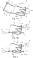
- connection elements 34 shows an end view from the outside of an end face of the test envelope 2 in the area of the connection elements 34.
- the lead-through elements 18 with the two half-shells can also be seen, which are guided around the connecting element 34 following the outer contour thereof.
- the plastic film 10 and the closure elements 8 can be seen, which are designed, for example, in the manner of strip-like clip closures.
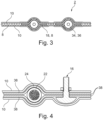
- the wall 2 is formed by an outer, in particular insulating layer, which is formed by a plastic film 10 and an inner conductive layer, which is in particular by a Tissue or braid 38 is formed.
- This consists, for example, of fine and finest metal wires or of metalized plastic or textile threads.
- the structure of the cable 20 with the inner conductor 22 and the insulation 24 (core sheath) can also be seen in this cross-sectional illustration.
- the measuring connection 16 is formed by a bolt-shaped element which contacts the braiding 38 on the inside and is routed to the outside.
- this is specifically a screw bolt, specifically with a flat head arranged on the inside, for example with a lens-shaped head.
- the screw is mechanically firmly connected to the wall 12 by means of a nut.
- the exemplary embodiment shows that the screw clamps two layers of the mesh 38 against one layer of the plastic film 10 . Alternatively, only one layer of the mesh 38 is braced.
- the measuring device 32 is electrically connected to this measuring connection 16 by means of a clamp, for example.
- the high flexibility of the wall 12 is essential for the method presented here, so that its conductive layer nestles against the cable harness 4 and its outer contour.
- the wall 12 has a comparatively small thickness D. This is preferably a maximum of 300 ⁇ m or less, depending on the configuration and structure of the wall 12.
- the thickness of the wall is defined by the entire structure of the wall 12, with a single-layer structure by the thickness D of one layer, eg the plastic film 10, and in a multi-layer construction by the total thickness of the multiple layers.
Description
- Die Erfindung betrifft ein Verfahren sowie eine Vorrichtung zur Prüfung der Isolation eines elektrischen Bauteils, insbesondere eines Kabels, speziell eines Kabelsatzes und insbesondere eines Hochvolt-Kabels (HV-Kabel) bzw. eines Hochvolt - Kabelsatzes (HV-Kabelsatz).
- Kabelsätze bestehen allgemein aus mehreren miteinander verbundenen Komponenten. So werden bei Kabelsätzen typischerweise mehrere Einzelleitungen oder Einzelkabel zusammengefasst und bilden typischerweise eine verzweigte Struktur aus. Die einzelnen Leitungen oder Kabel sind dabei vorkonfektioniert, weisen endseitig also bereits Kontaktelemente oder auch Stecker auf. Einzelne Kabel können innerhalb des Kabelsatzes auch miteinander verbunden sein, beispielsweise über Verteiler oder Verbinder etc.
- Bei der Herstellung eines Kabelsatzes werden mehrere Konfektionierungsschritte durchlaufen. Am Ende einer Kabelsatzfertigung erfolgt generell eine Funktionsprüfung. Unter anderem wird bei dieser auch die Integrität der Isolation des Kabelsatzes überprüft. Bei dieser auch als "Isolationstest" beschriebener Prüfung wird beispielsweise sichergestellt, dass keine spannungsführenden Leiterteile durch einen Isolationsmantel durchgedrungen sind und/oder dass die Integrität der Isolation sichergestellt ist. Bei geschirmten HV-Kabeln kann dazu ein Isolationswiderstand der Isolierung gegen den um den inneren Leiter angebrachten Schirm gemessen werden.
- Bei ungeschirmten HV-Kabeln oder HV-Kabelsätzen besteht diese Möglichkeit nicht. Als ein Standardverfahren wird der Kabelsatz in ein Salzwasserbad getaucht, sodass der Kabelsatz komplett vom Bad umschlossen ist. Bei dieser Variante wird der Isolationswiderstand zwischen dem eigentlichen Hochvolt-Leiter und einem Salzbad-Behälter gemessen. Allerdings ist diese Messung aufwendig und zudem hinterlässt sie Salzwasserrückstände am Kabelsatz.
- Zur Detektion von Schäden an der Isolierung von elektrischen Leitungen ist aus der
DE 100 24 809 B4 eine Prüfzange zu entnehmen, mittels der die zu überprüfende Leitung zangenartig umfasst werden kann. In dem von der Zange umgriffenen Teilbereich der Leitung wird dabei ein abgeschlossener Prüfraum geschaffen, in den ein Prüfgas mit geringer Durchschlagspannung eingeleitet wird. Nach Anlegen einer Prüfspannung wird der Prüfraum im Hinblick auf Entladungen überprüft. - Aus der
DE 33 09 658 A1 ist eine Vorrichtung zur optischen Prüfung der Durchschlagsfestigkeit einer elektrischen Isolation zu entnehmen, bei der eine Platte mit seitlichem Dichtungselement auf die zu prüfende Isolation aufgesetzt wird und zwischen der Platte und der zu prüfenden Isolation ebenfalls ein Prüfraum eingeschlossen ist, welcher beispielsweise evakuiert oder mit einem Testgas befüllt wird. - Aus der
DE 28 016 49 A1 ist eine Prüfvorrichtung zu entnehmen, bei der ein zu prüfendes Kabel in eine das Kabel umgebende Röhre eingelegt wird und ebenfalls mit einem Prüfgas gefüllt wird. - Aus der
DE 10 2016 116 695 A1 ist ein Verfahren zum Überprüfen eines Kabelbaums zu entnehmen, bei dem an einem Kabel in einem Prüfabschnitt eine Manschette angelegt wird, um zu überprüfen, ob eine spezielle Prüfleitung des Kabelsatzes in dem Prüfabschnitt liegt. - Aus der
US 6 518 772 B1 ist eine Prüfzange zur Überprüfung eines Kabelsatzes zu entnehmen. Die Prüfzange weist zwei aneinander gelagerte Arme auf und umgreift den zu prüfenden Kabelsatz. Über stirnseitige Dichtungen ist ein Prüfraum gebildet, in dem ein Prüfmedium eingebracht wird. Die Prüfzange wird zum Testen des Kabels sukzessive am Kabel entlang geführt. - Aus der
KR 2001 0056483 A - Aus der
JP S63 273073 A - Aus
US 2001 / 052 778 A1 ist eine Prüfvorrichtung zu entnehmen, die einen seitlich offenen, aufblasbaren Schlauch aufweist, durch den das zu prüfende Kabel hindurchgeführt wird. Dabei ist vorgesehen, dass der Schlauch entlang des Kabels verfahren wird, um unterschiedliche Regionen des Kabels zu überprüfen - Die aus dem Stand der Technik bekannten Messverfahren und Prüfverfahren sind häufig vergleichsweise aufwendig. Darüber hinaus ist bei vielen Prüfverfahren als nachteilig anzusehen, dass sie lediglich einzelne Abschnitte von Kabeln prüfen.
- Ausgehend hiervon liegt der Erfindung die Aufgabe zugrunde, ein Verfahren sowie eine Vorrichtung zur Prüfung der Isolation eines elektrischen Bauteils, insbesondere eines HV-Kabelsatzes anzugeben.
- Die auf das Verfahren gerichtete Aufgabe wird gelöst durch ein Verfahren zur Prüfung der Isolation eines elektrischen Bauteils mit den Merkmalen des Anspruchs 1. Bei dem elektrischen Bauteil handelt es sich insbesondere um ein Kabel, speziell um einen Kabelsatz, insbesondere um ein Hochvolt-Kabel (HV-Kabel), speziell um ein Hochvolt -Kabelsatz (HV-Kabelsatz).
- Grundsätzlich eignet sich das nachfolgend beschriebene Verfahren sowie die Vorrichtung auch zur Prüfung von anderen elektrischen Bauteilen, beispielsweise ein elektrisches Gerät, bei dem elektrische Komponenten von einem Isolationsgehäuse umgeben sind. Das elektrische Bauteil weist allgemein einen elektrischen Kern auf, welcher von der zu prüfenden Isolation umgeben ist. Die Isolation ist beispielsweise ein Kabelmantel und / oder ein Isolationsgehäuse. Beim bestimmungsgemäßen Gebrauch des elektrischen Bauteils ist an den elektrischen Kern eine Spannung angelegt. Bei einem Kabel handelt es sich bei dem elektrischen Kern insbesondere um einen Leiter, der von einem Kabelmantel als Isolierung umgeben ist. Bei mehrteiligen Kabeln, speziell mehradrigen Kabeln, ist der elektrische Kern gebildet durch die mehreren Leiter, die jeweils von einer Leiterisolation (Adermantel) umgeben sind und jeweils eine Ader bilden. Das mehradrige Kabel ist von einem gemeinsamen Kabelmantel umgeben, der zumindest ein Teil der zu prüfenden Isolation ist.
- Zur Prüfung, ob die Isolation einen Fehler aufweist, wird eine Prüfhülle bereitgestellt, in der das zu prüfende Bauteil bei der Prüfung einliegt. Die Prüfhülle weist dabei eine Wandung aus einem flexiblen und elektrisch leitfähigen Material auf, wobei die Flexibilität der Prüfhülle derart beschaffen ist, dass sie sich an die Isolation flächig anlegt, so dass sie eine Außenkontur der Isolation aufnimmt und diese nachbildet.
- Bei der Prüfung wird an den elektrischen Kern eine Prüfspannung angelegt und durch eine geeigente Messung ermittelt, ob die Isolierung den Qualitätsanforderungen entspricht oder ob die Isolation schadhaft ist. Die Prüfhülle wird daher nach Art einer Elektrode eingesetzt. Insbesondere wird geprüft, ob über die Messhülle ein Leckstrom abfließt und insbesondere auch, wie hoch dieser Leckstrom ist, um zu entscheiden, ob dieser einen kritischen Wert überschreitet. Alternativ wird das an der Messhülle anliegende Potential, beispielsweise gegenüber einem Bezugspotenzial gemessen. Allgemein wird daher eine elektrische Eigenschaft der Prüfhülle gemessen und anhand des Messergebnisses ermittelt, ob die Isolierung den Qualitätsanforderungen entspricht oder schadhaft ist.
- Der besondere Vorteil bei diesem Verfahren ist in der Prüfhülle mit der flexiblen, elektrisch leitfähigen Wandung zu sehen. Durch diese Maßnahme besteht die Möglichkeit, das zu überprüfende Bauteil, speziell einen HV-Kabelsatz vollständig oder zumindest nahezu vollständig in die Prüfhülle einzulegen und dann die gesamte Isolation des Bauteils mit nur einer Messung zu überprüfen. Wesentlich ist hierbei, dass aufgrund der Flexibilität der Prüfhülle diese der Außenkontur der Isolierung folgt, sodass auch lokale Schadstellen zuverlässig erfasst werden.
- Ein weiterer Vorteil der Messmethode mit dieser flexiblen Prüfhülle ist darin zu sehen, dass keine zusätzlichen Medien, wie beispielsweise Salzwasser oder spezielle Prüfgase eingebracht werden, die dann in einem Zwischenraum zwischen der als Elektrode dienenden Prüfhülle und der Isolation angeordnet sind. Es wird daher auf derartige zusätzliche Prüfmedien, wie Prüfgas oder Prüfflüssigkeit verzichtet. Die Prüfhülle liegt unmittelbar und flächig an der Isolation an.
- Bei der Prüfhülle handelt es sich dabei um eine Prüftasche, die das zu prüfende Bauteil in sich aufnimmt. Unter einer "Prüftasche" wird dabei allgemein verstanden, dass diese zwei gegenüberliegende Hüllflächen aufweist, die - zumindest bei der Durchführung des Prüfverfahrens oder alternativ dauerhaft - an zumindest drei Randseiten miteinander verbunden sind. Bevorzugt sind die Randseiten über ein Verschlusselement insbesondere reversibel verschließbar. Die Prüftasche definiert daher einen geschlossenen Prüfraum, welcher lediglich zu einer Randseite hin eine Öffnung aufweist. Während des Prüfvorgangs ist diese vorzugsweise ebenfalls verschließbar. In der Prüftasche liegt bei der Prüfung das Bauteil ein, vorzugsweise vollständig ein. Die Prüftasche bildet daher einen geschlossenen Prüfraum, welcher nur zu einer Seite hin die insbesondere verschließbare Öffnung aufweist. An dieser Öffnung ist bei der Prüfung zumindest ein Ende des Bauteils, vorzugsweise mehrere Enden des Bauteils zum Anschluss an eine Spannungsversorgung, speziell zum Anschluss an die Prüfspannung herausgeführt. Die herausgeführten Enden sind speziell durch Kontaktanschlüsse gebildet. Alternativ liegt das Bauteil vollständig in der Prüfhülle ein und der Spannungsanschluss erfolgt über die Öffnung mittels eines Anschlusselements.
- Allgemein nimmt die Prüfhülle das Bauteil zumindest weitgehend vollständig auf. Unter "weitgehend vollständig" wird hierbei verstanden, dass das zu prüfende Bauteil bis auf eventuelle Anschlussbereiche des zu prüfenden Bauteils vollständig in der Prüfhülle einliegt. Die Anschlussbereiche des Bauteils, die aus der Prüfhülle herausgeführt werden, dienen zum Anlegen der Prüfspannung. Im Falle eines HV-Kabelsatzes werden daher allenfalls die beispielsweise mit einem Stecker vorkonfektionierten Enden herausgeführt, der Rest des Kabelsatzes, also beispielsweise zumindest 90% (der gesamten Kabellänge) werden in der Prüfhülle aufgenommen. Bevorzugt liegt das komplette zu prüfende Bauteil, insbesondere der HV-Kabelsatz in der Prüfhülle, speziell in der Prüftasche ein.
- Das nachfolgend beschriebene Prüfverfahren mit der speziellen Prüfhülle kann gleichermaßen auch für Prüfsituationen herangezogen werden, bei denen das Bauteil alternativ nur teilweise, beispielsweise in Abschnitten in der Prüfhülle einliegt, die wiederum als Prüftasche ausgebildet sein kann.
- Unter Kabelsatz wird vorliegend verstanden, dass mehrere einzelne Kabel oder Leitungen zu einer Einheit miteinander verbunden sind und typischerweise eine verzweigte Struktur ausbilden. Häufig sind die einzelnen Kabel dabei beispielsweise über Verteiler oder Verbinder miteinander verbunden oder zumindest endseitig mit Kontaktelementen und/oder Steckerelementen vorkonfektioniert.
- Unter Hochvolt-Kabel oder - Kabelsatz wird verstanden, dass das jeweilige Kabel bzw. der jeweilige Kabelsatz dabei jeweils für hohe Spannungen von insbesondere mehr als 250 Volt, vorzugsweise mehr als 500 Volt oder auch mehr als 1.000 Volt und vorzugsweise bis maximal 1.500 bis 2.000 Volt ausgelegt ist. Die HV-Kabel sind typischerweise zur Leitung von hohen Strömen ausgelegt und weisen entsprechend einen großen Leiterquerschnitt von beispielsweise mehreren Quadratmillimetern (mm2) beispielsweise mehr als 2,5 mm2 auf. Derartige HV-Kabelsätze werden beispielsweise in der Automobilindustrie eingesetzt, speziell für Kraftfahrzeuge mit elektrischem Fahrmotor (Elektro-Fahrzeug oder HybridFahrzeug).
- Bei dem einzelnen HV-Kabel handelt es sich typischerweise um eine einadrige Leitung, die entweder nach Art einer Koaxialleitung mit einem Schirm als Außenleiter versehen ist oder bei der kein Schirm angeordnet ist. In letzterem Fall besteht das HV-Kabel beispielsweise lediglich aus dem Leiter und der diesen umgebende Isolierung, die also einen Ader- oder Kabelmantel bildet. Grundsätzlich kann das einzelne HV-Kabel auch ein mehradriges Kabel sein, bei dem die einzelnen Kabeladern von einem gemeinsamen Isolationsmantel als Isolierung umgeben sind.
- Gemäß einer bevorzugten Ausgestaltung wird in der Prüfhülle bei einliegendem Bauteil ein Unterdruck gegenüber einem außerhalb der Prüfhülle herrschenden Druck erzeugt. Hierdurch schmiegt sich die Prüfhülle, also ihre Wandung, an die Isolation an und berührt die Isolation großflächig, insbesondere vollflächig. Unter "großflächig" wird verstanden, dass die Isolation zu mehr als 60%, vorzugsweise zu mehr als 80% und insbesondere zu mehr als 90% von der Prüfhülle berührt wird. D.h. lediglich ein kleiner Anteil der Oberfläche der zu prüfenden Isolation wird nicht von der Prüfhülle berührt.
- Unter "Unterdruck" wird hierbei ein Unterdruck von zumindest 150 hPa (150mbar), vorzugsweise von zumindest 250 hPa verstanden. Vorzugsweise beträgt der Unterdruck maximal 1000 hPa (1 bar) und speziell maximal 500 hPa. Bevorzugt wird ein Unterdruck im Bereich von 200 hPa und 500 hPa eingestellt.
- Die Prüfhülle weist hierzu vorzugsweise einen Sauganschluss auf, an den zum Erzeugen des Unterdrucks eine Saugleitung angeschlossen wird. Bei dem Sauganschluss handelt es sich beispielsweise um ein hülsen- oder buchsenförmiges Element, welches insbesondere dichtend in die Wandung eingebracht ist und einen Strömungsweg in den Innenraum der Prüfhülle ermöglicht. Die Buchse besteht dabei typischerweise aus einem im Vergleich zur Wandung deutlich steiferen Material, speziell Kunststoff. Bevorzugt weist der Sauganschluss ein insbesondere automatisch wirkendes Verschlussventil, wie einen Membranverschluss auf, welcher ein Einströmen von Luft nach Erzeugen des Unterdrucks verhindert.
- In bevorzugter Ausgestaltung ist die Prüfhülle weiterhin bei einliegendem Bauteil luftdicht verschließbar. Je nach Flexibilität und Oberflächenbeschaffenheit der Prüfhülle kann auf ein Verschlusselement verzichtet werden, da beim Anlegen eines Unterdrucks gegenüberliegende Wandungsbereiche der Prüfhülle aufeinandergezogen werden und dann evtl. sogar selbstdichtend sind.
- Bevorzugt sind jedoch für das insbesondere luftdichte Verschließen ein oder mehrere separate Verschlusselemente vorgesehen. Beispielsweise lassen sich Randbereiche der Prüfhülle über einen Zipp-Verschluss oder über Haft- oder Klebestreifen verschließen. Dieses zumindest eine Verschlusselement ist dabei insbesondere integraler Bestandteil der Wandung, also mit dieser fest verbunden.
- Weiterhin sind erforderliche Durchführungen, beispielsweise für die Durchführung der Endbereiche des zu prüfenden Kabelsatzes, zweckdienlicherweise als luftdichte Durchführungen ausgebildet. Hierzu sind beispielsweise in die Prüfhülle integrierte, bevorzugt halbschalenartige Verstärkungen oder Abdichtelemente eingearbeitet, die dann um den durchgeführten Kabelabschnitt gelegt werden und diesen jeweils dichtend umschließen. Ergänzend können noch von außen randseitig angebrachte Fixierklammern etc. vorgesehen sein, die die Prüfhülle gegen den durchgeführten Teilbereich des Kabels drücken.
- Weiterhin weist die Prüfhülle vorzugsweise einen Messanschluss zum Anschluss eines Messgeräts auf, mittels dessen die elektrische Eigenschaft gemessen wird, insbesondere die Prüfhülle auf eine anliegende Spannung überprüft wird. Der Messanschluss ist beispielsweise ein Kontaktbolzen, eine Kontaktbuchse oder ein sonstiges Steckelement.
- Das Bauteil weist allgemein zumindest einen Kontaktanschluss auf, an dem beim bestimmungsgemäßen Gebrauch eine Spannung anliegt. Bei einem Kabel oder einem Kabelsatz handelt es sich hierbei um ein endseitig angeschlagenes Kontaktelement, insbesondere um einen Kabel(satz)stecker. Üblicherweise weist der Kabelsatz mehrere solcher Kabelsatzstecker auf.
- In bevorzugter Ausgestaltung liegt während der Prüfung zumindest ein oder mehrere derartiger Kontaktanschlüsse, insbesondere Kabeslsatzstecker, in der Prüfhülle ein. Zumindest ein Anschlussende des zu prüfenden Bauteils liegt daher in der Prüfhülle ein. Hierdurch wird bei der Prüfung zugleich auch die Isolationsfestigkeit des angeschlossenen Kontaktelements überprüft.
- Um eine vollständige Prüfung des gesamten Bauteils, speziell Kabelsatzes, zu ermöglichen, liegt der Kabelsatz vollständig innerhalb der Prüfhülle ein. Vorzugsweise ist hierzu ein Anschlusselement ausgebildet, welches in die Prüfhülle integriert ist, und an das das im Inneren der Prüfhülle liegende Bauteil, speziell der Kabelsatz, über den Kontaktanschluss anschließbar ist. Bei dem Anschlusselement handelt es sich insbesondere um ein Steckerelement, welches also einen Gegenstecker zum Kabelsatzstecker bildet. Hierdurch entfällt die Notwendigkeit, ein Teilstück des zu prüfenden Bauteils aus der Prüfhülle herauszuführen. Das Bauteil, speziell der Kabelsatz, ist daher im Inneren der Prüfhülle speziell über eine Steckverbindung an das integrierte Anschlusselement angeschlossen.
- Das Anschlusselement selbst ist wiederum bevorzugt abgedichtet durch die Wandung der Prüfhülle geführt und weist außenseitig einen Anschlusskontakt, beispielsweise einen Steckkontakt zum Anlegen der Prüfspannung auf.
- Über die Kontaktanschlüsse des Bauteils wird allgemein bei der Prüfung die Prüfspannung entweder direkt oder mittelbar über das integrierte Anschlusselement angelegt.
- Bei der Wandung handelt es sich allgemein um eine hochflexible, speziell folienartige oder auch stoffartige Umhüllung. Diese weist eine geringe Steifigkeit auf, sodass sie sich ohne Weiteres an die Außenkontur des zu prüfenden Bauteils speziell bei der Anlegung des Unterdrucks anschmiegen kann. Insbesondere weist die Wandung eine Wandungsstärke oder Dicke im Bereich bis maximal 300 µm, vorzugsweise bis maximal 200 µm oder bis maximal 100 µm auf.
- Speziell weist die Wandung einen folienartigen Charakter auf, wie es beispielsweise allgemein bei der Verpackung von Lebensmitteln, speziell bei der vakuumdichten Verpackung von Lebensmitteln, beispielsweise mittels sogenannter Gefrierbeutel, bekannt ist.
- Insgesamt ist die Wandung der Prüfhülle vorzugsweise durch eine leitfähige Kunststofffolie oder durch eine mit einer leitfähigen Beschichtung versehene Kunststofffolie gebildet.
- In einer bevorzugten Alternative weist die Wandung eine insbesondere nicht leitfähige Folie sowie eine weitere, leitfähige Lage auf. Die leitfähige Lage ist insbesondere als ein Gewebe oder ein Geflecht aus leitfähigen Fasern/Fäden, beispielsweise Feinstdrähten, gebildet. Die leitfähige Lage ist nach innen in Richtung zum Innenraum der Prüfhülle orientiert und durch eine gasdichte äußere Lage bildende Folie nach außen gebildet.
- Insbesondere bei dieser Ausführungsvariante mit der innenliegenden leitfähigen Lage ist der Messanschluss beispielsweise durch ein durch die Folie hindurchgeführtes Kontaktelement verwirklicht, welches mit der Wandung befestigt ist. Speziell handelt es sich hierbei um ein mechanisch befestigtes Element, beispielsweise eine Kontaktschraube. Das Kontaktelement ist bevorzugt luftdicht durch die äußere durch die Folie gebildete Lage hindurchgeführt. Grundsätzlich kann dieses Prinzip der Kontaktierung mit einem durch die Wandung hindurchgeführten Kontaktelement auch bei der Verwendung einer leitfähigen oder mit einer leitfähigen Beschichtung versehenen Folie eingesetzt werden.
- In einer bevorzugten Ausführungsvariante ist die Prüfhülle, speziell deren Wandung im Ausgangszustand als eine beispielsweise einlagige Folienlage ausgebildet, wobei das zu prüfende Bauteil zunächst auf einen ersten Teil, nämlich ein Unterteil der Prüfhülle, aufgelegt wird und anschließend ein weiteres Teil, nachfolgend als Oberteil bezeichnet, über das zu prüfende Bauteil gelegt wird. Das heißt, die Folienlage wird quasi einmal gefaltet und überdeckt dann mit Ober- und Unterteil das zu prüfende Bauteil vollflächig. Anschließend erfolgt vorzugsweise das bereits zuvor beschriebene luftdichte Verschließen der verbleibenden offenen Seitenteile. Das oder die Verschlusselemente verlaufen insbesondere entlang der offenen Randseiten beispielsweise U-förmig.
- In bevorzugter Ausgestaltung verbleibt das zu prüfende Bauteil nach der Prüfung in der Prüfhülle und diese wird als eine Schutzhülle oder auch als eine Transportverpackung beispielsweise nach Art eines Einwegartikels verwendet. Hierdurch erfüllt also die Prüfhülle eine Doppelfunktion, nämlich einerseits zum Prüfen des Kabelsatzes als auch als Transportverpackung bis zu einem vorgesehenen Einsatzort. Neben der Ausgestaltung als Einwegartikel wird die Prüfhülle alternativ nach Art eines Kreislaufsystems wiederkehrend für die Prüfung auch von weiteren Bauteilen eingesetzt.
- Die Aufgabe wird erfindungsgemäß weiterhin gelöst durch eine Vorrichtung zum Prüfen der Isolation eines elektrischen Bauteils mit den Merkmalen des Anspruchs 14
- Die zuvor im Hinblick auf das Verfahren angeführten Vorteile und bevorzugten Ausgestaltungen sind sinngemäß auch auf die Vorrichtung zu übertragen.
- Die Vorrichtung weist die Prüfhülle und vorzugsweise weiterhin ein Messgerät und vorzugsweise auch eine Vakuumpumpe auf.
- Ausführungsvarianten der Erfindung werden nachfolgend anhand der Figuren näher erläutert. Diese zeigen jeweils in stark vereinfachten Darstellungen:
- Fig. 1A
- eine Prüfhülle in aufgeklapptem Zustand mit einem aufgelegten HV-Kabelsatz,
- Fig. 1B
- die Prüfhülle gemäß
Fig. 1A im geschlossenen Zustand mit darin einliegendem HV-Kabelsatz, - Fig. 2
- eine zweite Ausführungsvariante einer Prüfhülle mit einem darin einliegenden HV-Kabelsatz,
- Fig. 3
- eine Stirnansicht auf eine geschlossene Prüfhülle im Bereich einer stirnseitigen Durchführung sowie
- Fig. 4
- eine ausschnittsweise Schnittdarstellung einer Ausführungsvariante der Prüfhülle mit integriertem Messanschluss.
- In den Figuren sind gleich wirkende Teile mit den gleichen Bezugszeichen dargestellt.
-
Fig. 1A zeigt eine Prüfhülle 2, die im dargestellten Ausführungsbeispiel eine aufgeklappte Folienlage 6 aufweist mit einem ersten Teil, nachfolgend als Unterteil 6A bezeichnet sowie einem weiteren Teil, nachfolgend als Oberteil 6B bezeichnet. Auf dem Unterteil 6A liegt das Bauteil in Form eines Kabelsatzes 4 auf. Nach dem Auflegen des Kabelsatzes 4 werden die beiden Teile 6A,6B wie durch den Pfeil inFig. 1A angedeutet, aufeinander geklappt, sodass das Oberteil 6B auf dem Unterteil 6A unter Zwischenlage des Kabelsatzes 4 aufliegt. Die beiden Teile 6A,6B bilden dadurch insgesamt eine Prüftasche aus, in der der Kabelsatz 4 einliegt. Alternativ hierzu ist die Prüfhülle 2 bereits im Ausganszustand als eine Prüftasche ausgebildet, die nur zu einer Seite offen ist, über die das zu prüfende Bauteil eingelegt wird. - Zum insbesondere luftdichten Verschließen weist die Prüfhülle 2 ein oder mehrere Verschlusselemente 8 auf. Diese verlaufen vorzugsweise randseitig und sind beispielsweise nach Art einer Verschlussleiste ausgebildet, wie beispielsweise ein Zipp-Verschluss oder ein Druckverschluss. Beim Druckverschluss werden - wie z.B. aus dem Bereich der Gefrierbeutel bekannt - zwei Profilleisten miteinander zum Verschließen ineinander gepresst. Alternativ ist das Verschlusselement als ein Haft- oder Klebestreifen ausgebildet. Dieser verläuft beispielsweise randseitig sowohl entlang des Oberteils 6B als auch entlang des Unterteils 6A, wie dies in der
Fig. 1A dargestellt ist. - Die Folienlage 6 ist dabei beispielsweise durch eine Kunststofffolie 10 gebildet, die entweder eine intrinsische Leitfähigkeit aufweist oder mit einer leitfähigen Beschichtung versehen ist. Schließlich besteht auch die Möglichkeit, dass zusätzlich eine leitfähige Lage angeordnet ist, wie dies in
Fig. 4 dargestellt ist. Die Prüfhülle 2 weist weiterhin allgemein eine Wandung 12 auf, die im Ausführungsbeispiel derFig.1B durch die Kunststofffolie 10 gebildet ist. Durch die Wandung 12 ist die Prüfhülle 2 zur Umgebung hin insbesondere luftdicht abgeschlossen. Die Wandung schließt insofern - bei einligendem Kabelsatz 4, wenn die Prüfhülle 2 eine Prüftasche bildet - einen Innenraum der Prüfhülle zur Umgebung hin ab. Die Wandung 12 ist gasdicht ausgebildet. - Ergänzend weist die Prüfhülle 2 einen Sauganschluss 14 sowie einen Messanschluss 16 auf.
- Der Sauganschluss 14 sowie der Messanschluss 16 sind jeweils integrierte Bestandteile der Prüfhülle 2 und insbesondere mit der Wandung 12 fest verbunden.
- Die Prüfhülle 2 weist weiterhin Durchführungselemente 18 auf, die insbesondere zum abgedichteten, luftdichten Durchführen zumindest eines Elementes durch eine verbleibende (Befüll-) Öffnung der zur Prüftasche ausgebildeten Prüfhülle 2 dienen. Bei dem Element handelt es sich im Ausführungsbeispiel der
Fig. 1A, 1B um ein Kabel 20 des Kabelsatzes 4. Diese Durchführungselemente 18 dienen daher ebenfalls als Verschlusselemente 8. Sie sind beispielsweise jeweils nach Art von Halbschalen aus einem Dichtmaterial, beispielsweise Kunststoff oder Gummi, ausgebildet und sind jeweils vorzugsweise fest mit der Kunststofffolie 10 verbunden. Ein jeweiliges Paar an Halbschalen bildet dabei jeweils ein Durchführungselement 18. Die Halbschalen lassen sich beispielsweise miteinander durch lösbare Verbindungen, beispielsweise eine Clip-Verbindung oder auch eine Klett-Verbindung etc., miteinander verbinden. - Die aus der Prüfhülle 2 herausgeführten Endstücke des Kabelsatzes 4 werden daher einfach auf die jeweiligen Halbschalen aufgelegt und anschließend beim Verschließen der Prüfhülle 2 werden die jeweiligen Oberteile der Halbschalen mit den Unterteilen verbunden, sodass die jeweiligen Kabel 20 luftdicht herausgeführt sind.
- Der Kabelsatz 4 weist allgemein mehrere Kabel 20 auf, die jeweils als HV-Kabel ausgebildet sind. Im Ausführungsbeispiel ist ein jeweiliges Kabel 20 als ein einadriges Kabel ausgebildet, welches lediglich einen zentralen Leiter 22 als einen elektrischen Kern aufweist, welcher von einer Isolation 24 direkt umgeben ist, die also einen Adermantel ausbildet (vgl. hierzu
Fig. 4 ). Der Kabelsatz 4 weist an einer Anschlussseite im Ausführungsbeispiel zwei vorkonfektionierte elektrische, erste Kontaktanschlüsse 26A auf, die bevorzugt nach Art von Steckern ausgebildet sind und insofern Kabelsatzstecker bilden. Die ersten Kontaktanschlüsse 26A sind in der inFig. 1A, 1B dargestellten Situation außerhalb der Prüfhülle 2 angeordnet. Daneben weist der Kabelsatz 4 weitere elektrische, zweite Kontaktanschlüsse 26B auf, die innerhalb der Prüfungshülle 2 angeordnet sind. - Der Kabelsatz 4 weist insgesamt eine verzweigte Struktur auf mit mehreren Kabeln 20, die im Ausführungsbeispiel über Verteiler 28. miteinander verbunden sind. Bei den Verteilern 28 handelt es sich um 1-2-Verteiler, d.h. ein eingehendes Kabel 20 wird auf zwei ausgehende Kabel 20 aufgeteilt. An den inneren, zweiten Kontaktanschlüssen 26B sind jeweils zwei Kabel 4 angeschlossen. In diesen zweiten Kontaktanschlüssen 26B liegen dabei jeweils (Steck-)Kontaktelemente ein, es handelt sich also bei diesen insbesondere um zweipolige Kontaktanschlüsse 26B. Bei den äußeren, ersten Kontaktanschlüssen 26A handelt es sich demgegenüber vorzugsweise um einpolige Kontaktanschlüsse 26A, die im Betrieb mit einem Pluspol bzw. Minuspol einer Versorgungsspannung, z.B. einer Batterie verbunden sind.
- Zur Prüfung der Isolation 24 des Kabelsatzes 4 sind vorzugsweise die beiden Kontaktelemente der innenseitig angeordneten zweiten Kontaktanschlüsse 26 B elektrisch miteinander verbunden.
- Im Ausführungsbeispiel der
Fig. 1A sind die ersten Kontaktanschlüsse 26A des Kabelsatzes 4 nach außen durch die Durchführungen 18 herausgeführt. Der restliche Kabelsatz 4, insbesondere auch die zweiten Kontaktanschlüsse 26B, liegen in der Prüfhülle 2 für die nachfolgende Prüfung luftdicht abgeschlossen ein. Insgesamt liegt damit der Kabelsatz 4 nahezu vollständig in der Prüfhülle 2 ein. Hierunter wird verstanden, dass mindestens 90% der aufsummierten Länge der einzelnen Kabelstränge des Kabelsatzes 4 in der Prüfhülle 2 aufgenommen wird. Speziell wird zumindest ein Teil der jeweils endseitig an den einzelnen Kabeln 20 angeschlagenen Kontaktanschlüsse 26B von der Prüfhülle 2 mit aufgenommen. - Im nachfolgend noch genauer beschriebenen Ausführungsbeispiel der
Fig. 2 ist der Kabelsatz 4 vollständig von der Prüfhülle 2 aufgenommen, d.h. sämtliche Kontaktanschlüsse 26A, 26B liegen im Inneren der Prüfhülle 2 ein. - Der Kabelsatz 4 definiert daher insgesamt ein zu überprüfendes elektrisches Bauteil, welches einen elektrischen Kern aufweist, der durch die einzelnen Leiter 22 der einzelnen Kabel 20 sowie aber auch durch die in den Kontaktanschlüssen 26B,26A einliegenden Kontaktelemente gebildet ist. Die Isolation 24 dieses Kabelsatzes 4 wird gebildet zum einen durch die Adermäntel der einzelnen Kabel 20 sowie aber auch durch die einzelnen Isoliergehäuse der weiteren Bauteile, wie z.B. die Isoliergehäuse der Verteiler und der Kontaktanschlüsse 26B.
- Zur Überprüfung, ob die Isolation 24 fehlerhaft ist, wird bei dem Verfahren zur Prüfung der Isolation 24 wie folgt vorgegangen:
Zunächst wird der Kabelsatz 4 in die als Prüftasche ausgebildete Prüfhülle 2 eingelegt, d.h. der Kabelsatz 4 ist zumindest nahezu vollständig oder vollständig im Inneren der Prüfhülle 2 aufgenommen. Diese ist vorzugsweise luftdicht verschlossen. Über den Sauganschluss 14 wird anschließend beispielsweise mithilfe einer Vakuumpumpe 30 die im Inneren der Prüfhülle 2 verbleibende Luft abgesaugt und ein Unterdruck erzeugt. Aufgrund der Flexibilität der Wandung 12 und allgemein der Kunststofffolie 10 schmiegt sich die Wandung 12 flächig und der Außenkontur des Kabelsatzes 4 folgend an diese Außenkontur an. Hierbei wird ein Unterdruck gegenüber dem in der Umgebung herrschenden Druck von beispielsweise 300 bis 800 hPa erzeugt. - Zur Messung der Integrität der Isolierung 24 wird vorzugsweise jeweils an einen der beiden äußeren zweiten Kontaktanschlüsse 26B mithilfe eines Test- oder Messgeräts 32 eine Prüfspannung U1 angelegt, die beispielsweise zumindest dem Spannungswert einer Betriebsspannung entspricht, mit der der Kabelsatz 4 im Betrieb beaufschlagt wird. Vorzugsweise wird jedoch eine deutlich höhere Spannung als die Betriebsspannung angelegt. Beispielsweise wird eine Prüfspannung von 1.000 Volt oder mehr angelegt. Beispielsweise wird eine Prüfspannung größer 1.500V und allgemein beispielsweise im Bereich zwischen 1kV bis 5kV angelegt.
- Die Spannung U1 wird insbesondere zwischen jeweils einem der beiden Kontaktanschlüsse 26B und dem Messanschluss 16 angelegt. Mithilfe des Messgeräts 32 wird bevorzugt ein evtl. fließender Leckstrom als Maß für den Widerstand der Anordnung gemessen.
- Für den Fall einer intakten Isolierung 24 fließt kein oder nur ein sehr geringer Leckstrom. Im Falle einer defekten Isolierung 24 treten beispielsweise Überschläge oder sogar eine Kontaktierung zwischen dem Leiter 22 und der Prüfhülle 2 auf, so dass dies zu einem messbaren signifikant höherem Leckstrom führen. Es wird aufgrund des gemessenen Leckstroms erkannt, ob die Isolation 24 den Qualitätsanforderungen entspricht. Innerhalb des Messgerätes 32 sind vorzugsweise Schwellenwerte für unzulässig hohe Leckströme parametriert.
- Der besondere Vorteil der hier vorgestellten Methode ist darin zu sehen, dass zum einen der Kabelsatz 4 zumindest weitgehend vollständig oder vollständig in der Prüfhülle 2 einliegt und damit der Kabelsatz 4 durch nur eine Messung vollständig auf Isolationsschäden überprüft wird. Insbesondere werden hierbei auch Konfektionierungsfehler beim Anschließen der Kontaktanschlüsse 26B erkannt, da diese ebenfalls in der Prüfhülle 2 einliegen. Gleiches gilt für die Verteiler 28.
- In der
Fig. 2 ist ein Ausführungsbeispiel dargestellt, bei dem auch die ersten Kontaktanschlüsse 26A im Inneren der Prüfhülle 2 beim Prüfverfahren einliegen. Bei dieser Ausführungsvariante werden daher auch diese bei der Prüfung mit überprüft. - Für diese Variante gemäß
Fig. 2 ist insbesondere vorgesehen, dass die Prüfhülle 2 integrierte Anschlusselemente 34 aufweist. Diese sind insbesondere fester Bestandteile der Prüfhülle 2 und beispielsweise mit der Wandung 12 fest verbunden. Diese Anschlusselemente 34 sind insbesondere als Steckelemente ausgebildet und bilden Gegenstecker für die Kabelsatzstecker, also speziell für die ersten Kontaktanschlüsse 26A. Die Anschlusselemente 34 selbst sind vorzugsweise luftdicht zur Wandung 12 hin abgedichtet und bilden quasi Durchführungen. Die Anschlusselemente 34 sind dabei vorzugsweise wiederum mittels Durchführungselementen 18, wie sie bereits zu derFig. 1A beschrieben wurden, abgedichtet. Die Anschlusselemente 34 sind beispielsweise im aufgefalteten Ausgangszustand der Folienlage 6 (vgl. hierzuFig. 1A ) beispielsweise mit den unteren Halbschalen der Durchführungselemente 18 verbunden oder bilden mit diesen ein integrales, einstückiges Element aus. - An diese Anschlusselemente 34 ist außenseitig das Messgerät 32 zum Anlegen der Prüfspannung U1 angeschlossen. Hierzu weist das Anschlusselement 34 vorzugsweise einen außenseitig liegenden Anschlusskontakt 36, beispielsweise eine Steckbuchse oder einen Steckerstift auf.
-
Fig. 3 zeigt eine Stirnansicht von außen auf eine Stirnseite der Prüfhülle 2 im Bereich der Anschlusselemente 34. In der Stirnansicht derFig. 3 sind weiterhin die Durchführungselemente 18 mit den beiden Halbschalen zu erkennen, die der Außenkontur des Anschlusselements 34 folgend um dieses herum geführt sind. Weiterhin sind die Kunststofffolie 10 sowie die Verschlusselemente 8 zu erkennen, die beispielsweise nach Art von leistenartigen Clip-Verschlüssen ausgebildet sind. -
Fig. 4 zeigt einen speziellen Aufbau der Wandung 12 der Prüfhülle 2. Und zwar ist in diesem Ausführungsbeispiel vorgesehen, dass die Wandung 2 gebildet ist durch eine äußere, insbesondere isolierende Lage, die durch eine Kunststofffolie 10 gebildet ist und eine innere leitfähige Lage, die insbesondere durch ein Gewebe oder Geflecht 38 gebildet ist. Dieses besteht beispielsweise aus feinen und feinsten Metalldrähten oder auch aus metallisierten Kunststoff- oder Textilfäden. Zu erkennen ist in dieser Querschnittsdarstellung auch der Aufbau des Kabels 20 mit dem innenliegenden Leiter 22 und der Isolation 24 (Adermantel). - Weiterhin ist zu erkennen, dass in diesem Ausführungsbeispiel der Messanschluss 16 gebildet ist durch ein bolzenförmiges Element, welches innenseitig das Geflecht 38 kontaktiert und nach außen geführt ist. Im Ausführungsbeispiel handelt es sich hierbei speziell um einen Schraubbolzen, speziell mit einem innenseitig angeordneten Flachkopf beispielsweise mit linsenförmigem Kopf. Mittels einer Mutter ist die Schraube mit der Wandung 12 mechanisch fest verbunden. Im Ausführungsbeispiel ist dargestellt, dass die Schraube zwei Lagen des Geflechts 38 gegen eine Lage der Kunststofffolie 10 verspannt. Alternativ wird nur eine Lage des Geflechts 38 verspannt. An diesen Messanschluss 16 wird das Messgerät 32 beispielsweise mittels einer Klemme elektrisch angeschlossen.
- Wesentlich für das hier dargestellte Verfahren ist die hohe Flexibilität der Wandung 12, sodass diese sich mit ihrer leitfähigen Lage an den Kabelsatz 4 und dessen Außenkontur anschmiegt. Um dies zu erreichen weist die Wandung 12 eine vergleichsweise geringe Dicke D auf. Diese liegt vorzugsweise bei maximal 300 µm oder auch darunter, je nach Ausgestaltung und Aufbau der Wandung 12. Die Dicke der Wandung ist dabei durch den gesamten Aufbau der Wandung 12 definiert, bei einem einlagigen Aufbau durch die Dicke D der einen Lage, z.B. der Kunststofffolie 10, und bei einem mehrlagigen Aufbau durch die Gesamtdicke der mehreren Lagen.
-
- 2
- Prüfhülle
- 4
- HV-Kabelsatz
- 6
- Folienlage
- 6A
- Unterteil
- 6B
- Oberteil
- 8
- Verschlusselement
- 10
- Kunststofffolie
- 12
- Wandung
- 14
- Sauganschluss
- 16
- Messanschluss
- 18
- Durchführungselement
- 20
- Kabel
- 22
- Leiter
- 24
- Isolation
- 26A
- erste Kontaktanschlüsse
- 26B
- zweite Kontaktanschlusse
- 28
- Verteiler
- 30
- Vakuumpumpe
- 32
- Messgerät
- 34
- Anschlusselement
- 36
- Anschlusskontakt
- 38
- Geflecht
- D
- Dicke
- U1
- Prüfspannung
Claims (14)
- Verfahren zur Prüfung der Isolation (24) eines elektrischen Bauteils, insbesondere eines HV-Kabelsatzes (4), wobei das elektrische Bauteil einen elektrischen Kern aufweist, der von der zu prüfenden Isolation (24) umgeben ist, wobei- eine Prüfhülle (2) bereitgestellt wird, in der das zu prüfende Bauteil bei der Prüfung zumindest weitgehend vollständig einliegt,- die Prüfhülle als eine Prüftasche ausgebildet ist, die zwei gegenüberliegende Hüllflächen aufweist, die zumindest bei der Durchführung des Prüfverfahrens an zumindest drei Randseiten miteinander verbunden sind, wobei die Prüftasche einen Prüfraum umschließt und in der Prüftasche das elektrische Bauteil einliegt,- die Prüfhülle (2) eine elektrisch leitfähige Wandung (12) aus einem flexiblen Material aufweist und es sich bei der Wandung (12) um eine folienartige oder stoffartige Umhüllung handelt,- die Prüfhülle (2) sich durch ihre Flexibilität an die Außenkontur der Isolation (24) anlegt,- an den elektrischen Kern eine Prüfspannung angelegt wird und geprüft wird, ob die Isolation (24) schadhaft ist.
- Verfahren nach dem vorhergehenden Anspruch, bei dem darauf verzichtet ist, in einen Zwischenraum zwischen der als Elektrode dienenden Prüfhüllle (2) und der Isolation (24) ein Prüfmedium einzubringen.
- Verfahren nach einem der vorhergehenden Ansprüche, bei dem die als eine Prüftasche ausgebildete Prüfhülle (2) nur zu einer Seite eine insbesondere verschließbare Öffnung aufweist, wobei durch die Öffnung vorzugsweise zumindest ein Ende oder ein Kontaktanschluss (26A, 26B) des elektrischen Bauteils herausgeführt ist an der Öffnung ein Anschlusselement (34) angeordnet ist.
- Verfahren nach einem der vorhergehenden Ansprüche, bei dem in der Prüfhülle (2) ein Unterdruck erzeugt wird, so dass sich die Prüfhülle (2) an die Isolation (24) anschmiegt und die Isolation (24) großflächig, insbesondere vollflächig berührt.
- Verfahren nach einem der vorhergehenden Ansprüche, bei dem die Prüfhülle (2) einen Sauganschluss (14) zum Erzeugen des Unterdrucks aufweist.
- Verfahren nach einem der vorhergehenden Ansprüche, bei dem die Prüfhülle (2) bei einliegendem Bauteil luftdicht verschließbar ist und hierzu vorzugsweise zumindest ein Verschlusselement (8) aufweist.
- Verfahren nach einem der vorhergehenden Ansprüche, bei dem die Prüfhülle (2) einen Messanschluss (16) zum Anschluss eines Messgeräts (32) aufweist.
- Verfahren nach einem der vorhergehenden Ansprüche, bei dem in der Prüfhülle (2) zumindest ein endseitiger Kontaktanschluss (26A, 26B) des Bauteils einliegt.
- Verfahren nach einem der vorhergehenden Ansprüche, bei dem die Prüfhülle (2) ein integriertes Anschlusselement (34) aufweist, an das das Bauteil im Inneren der Prüfhülle (2) anschließbar ist, wobei das Anschlusselement (34) insbesondere abgedichtet durch die Wandung (12) der Prüfhülle (2) geführt ist.
- Verfahren nach einem der vorhergehenden Ansprüche, bei dem die Wandung (12) eine Dicke (D) im Bereich bis maximal 300 µm, vorzugsweise maximal 200 µm oder maximal 100 µm aufweist.
- Verfahren nach einem der vorhergehenden Ansprüche, bei dem die Wandung (12) der Prüfhülle (2) durch eine leitfähige Kunststofffolie (10) oder durch eine mit einer leitfähigen Beschichtung versehene Kunststofffolie (10) gebildet ist, und/ oder
bei dem die Wandung (12) der Prüfhülle (2) eine Folie sowie eine weitere, leitfähige Lage aufweist, die insbesondere durch ein Gewebe gebildet ist.. - Verfahren nach einem der vorhergehenden Ansprüche, bei dem die Wandung (12) der Prüfhülle (2) im Ausganszustand als eine Folienlage (6) ausgebildet ist und das zu prüfende Bauteil auf einen Teil (6A) der Prüfhülle (2) aufgelegt wird und anschließend ein weiteres Teil (6B) der Prüfhülle (6A) über das zu prüfende Bauteil gelegt wird.
- Verfahren nach einem der vorhergehenden Ansprüche, bei dem das Bauteil nach der Prüfung in der Prüfhülle (2) verbleibt und diese als eine Transportverpackung verwendet wird.
- Vorrichtung zur Prüfung der Isolation (24) eines elektrischen Bauteils, insbesondere eines HV-Kabelsatzes (4), die eine Prüfhülle (2) aufweist, , die zwei gegenüberliegende Hüllflächen aufweist, die zumindest bei der Durchführung des Prüfverfahrens an zumindest drei Randseiten zur Ausbildung einer Prüftasche miteinander verbunden sind, wobei die Prüftasche einen Prüfraum umschließt und in die Prüftasche das zu prüfende elektrische Bauteil einlegbar ist und eine Wandung (12) aus einem elektrisch leitfähigem Material aufweist, wobei es sich bei der Wandung (12) um eine folienartige oder stoffartige Umhüllung handelt, und die Prüfhülle (2) durch die Wandung (12) zur Umgebung hin luftdicht abgeschlossen ist und die Prüfhülle (2) eine Flexibilität aufweist, so dass sie sich durch ihre Flexibilität an die Außenkontur der Isolation (24) anlegen kann, wobei die Prüfhülle (2) vorzugsweise ein oder mehrere der nachfolgenden Merkmale aufweist:- einen Sauganschluss (14) zum Erzeugen eines Unterdrucks innerhalb der Prüfhülle (2),- ein integriertes Anschlusselement (34) zum Anschluss eines Kontaktanschlusses (26A) des zu prüfenden Bauteils im Innern der Prüfhülle (2),- zumindest ein Verschlusselement (8) zum luftdichten Verschließen der Prüfhülle (2) sowie- einen Messanschluss (16) zum Anschließen eines Messgerätes (32).
Applications Claiming Priority (2)
| Application Number | Priority Date | Filing Date | Title |
|---|---|---|---|
| DE102019210866.0A DE102019210866B4 (de) | 2019-07-23 | 2019-07-23 | Verfahren sowie Vorrichtung zur Prüfung der Isolation eines elektrischen Bauteils, insbesondere eines HV-Kabelsatzes |
| PCT/EP2020/067066 WO2021013446A1 (de) | 2019-07-23 | 2020-06-19 | Verfahren sowie vorrichtung zur prüfung der isolation eines elektrischen bauteils, insbesondere eines hv-kabelsatzes |
Publications (2)
| Publication Number | Publication Date |
|---|---|
| EP4004569A1 EP4004569A1 (de) | 2022-06-01 |
| EP4004569B1 true EP4004569B1 (de) | 2023-08-02 |
Family
ID=71130957
Family Applications (1)
| Application Number | Title | Priority Date | Filing Date |
|---|---|---|---|
| EP20734345.0A Active EP4004569B1 (de) | 2019-07-23 | 2020-06-19 | Verfahren sowie vorrichtung zur prüfung der isolation eines elektrischen bauteils, insbesondere eines hv-kabelsatzes |
Country Status (3)
| Country | Link |
|---|---|
| EP (1) | EP4004569B1 (de) |
| DE (1) | DE102019210866B4 (de) |
| WO (1) | WO2021013446A1 (de) |
Families Citing this family (2)
| Publication number | Priority date | Publication date | Assignee | Title |
|---|---|---|---|---|
| US11573258B1 (en) * | 2021-08-16 | 2023-02-07 | Aptiv Technologies Limited | Apparatus and method for testing insulated high voltage devices |
| CN114705955B (zh) * | 2022-03-02 | 2023-04-25 | 中国电子科技集团公司第二十九研究所 | 一种聚四氟乙烯高压导线绝缘耐压测试装置及方法 |
Citations (1)
| Publication number | Priority date | Publication date | Assignee | Title |
|---|---|---|---|---|
| US20010052778A1 (en) * | 2000-06-07 | 2001-12-20 | Smith Paul Samuel | Device for detecting and locating insulation defects |
Family Cites Families (10)
| Publication number | Priority date | Publication date | Assignee | Title |
|---|---|---|---|---|
| FR2378286A1 (fr) * | 1977-01-21 | 1978-08-18 | Cefilac | Testeur de rigidite dielectrique a sec pour cable electrique isole |
| DE3309658A1 (de) * | 1983-03-17 | 1984-09-27 | Siemens AG, 1000 Berlin und 8000 München | Vorrichtung zur optischen pruefung der durchschlagsfestigkeit einer elektrischen isolation |
| JPS63273073A (ja) * | 1987-04-30 | 1988-11-10 | Oki Electric Ind Co Ltd | ケ−ブル絶縁試験方法 |
| KR100328186B1 (ko) * | 1999-12-15 | 2002-03-16 | 권문구 | 프리몰드 고무 슬리브 pd 시험치구 |
| US6518772B1 (en) * | 2000-05-16 | 2003-02-11 | Wee-Electrotest Engineering Gmbh | Method and device for the detection of damage in the insulation of electrical components, particularly of lines and cable harnesses |
| DE10024809B4 (de) * | 2000-05-16 | 2006-03-16 | Wee Electrotest Engineering Gmbh | Verfahren und Einrichtung zur Detektion von Schäden in der Isolation von elektrischen Leitungen und Kabelbäumen |
| DE102012214231A1 (de) * | 2012-08-10 | 2014-02-13 | Robert Bosch Gmbh | Verfahren und Vorrichtung zum Kontrollieren von Isolationseigenschaften eines Gehäuses für Batteriezellen |
| DE102012214738A1 (de) * | 2012-08-20 | 2014-02-20 | Robert Bosch Gmbh | Prüfvorrichtung und Verfahren zur Prüfung der elektrischen Isolation der Oberfläche von elektrischen Bauteilen |
| DE102016116695A1 (de) * | 2016-09-07 | 2018-03-08 | Espi Logistics Gmbh | Verfahren und Messvorrichtung zum Überprüfen eines Kabelbaumes |
| DE102017213922A1 (de) * | 2017-08-10 | 2019-02-14 | Robert Bosch Gmbh | Vorrichtung zur Prüfung der elektrischen Isolation einer Statorspule für eine elektrische Maschine |
-
2019
- 2019-07-23 DE DE102019210866.0A patent/DE102019210866B4/de active Active
-
2020
- 2020-06-19 EP EP20734345.0A patent/EP4004569B1/de active Active
- 2020-06-19 WO PCT/EP2020/067066 patent/WO2021013446A1/de unknown
Patent Citations (1)
| Publication number | Priority date | Publication date | Assignee | Title |
|---|---|---|---|---|
| US20010052778A1 (en) * | 2000-06-07 | 2001-12-20 | Smith Paul Samuel | Device for detecting and locating insulation defects |
Also Published As
| Publication number | Publication date |
|---|---|
| EP4004569A1 (de) | 2022-06-01 |
| DE102019210866A1 (de) | 2021-01-28 |
| WO2021013446A1 (de) | 2021-01-28 |
| DE102019210866B4 (de) | 2024-03-21 |
Similar Documents
| Publication | Publication Date | Title |
|---|---|---|
| DE102016117261B3 (de) | System aus einem Steckverbinder, einem fluidgekühlten Kabel und einer Anschlusseinheit | |
| EP4004569B1 (de) | Verfahren sowie vorrichtung zur prüfung der isolation eines elektrischen bauteils, insbesondere eines hv-kabelsatzes | |
| EP3495796B1 (de) | Vorrichtung und verfahren zum prüfen einer ladedose zum zuführen elektrischer energie zu einem energiespeicher eines fahrzeugs | |
| EP2091121B1 (de) | Vorrichtung für eine Verbindungsstelle zwischen zwei elektrischen Hochspannungskabeln mit unterschiedlichen Durchmessern | |
| WO2020114888A1 (de) | Anschlusselement zum elektrischen anschliessen einer fluidkühlbaren einzelleitung, fluidkühlbare einzelleitungseinheit und ladekabel | |
| EP2182602A1 (de) | Vorrichtung für eine Verbindungungsstelle zwischen zwei elektrischen Hochspannungskabeln | |
| DE102004046134A1 (de) | Freiluftendverschluss | |
| WO2019145139A1 (de) | Steckbare hochspannungsdurchführung und elektrisches gerät mit der steckbaren hochspannungsdurchführung | |
| EP1295136A1 (de) | Detektion von schäden in der isolierung von elektrischen komponenten | |
| DE19726419A1 (de) | Heizleiter-Verbindungssystem in einem Flugzeug | |
| DE102019120470A1 (de) | Steckverbinder mit Isolationsüberwachung | |
| DE2726403A1 (de) | Kabelgarnitur zum anschluss eines geschirmten starkstromkabels an ein elektrisches geraet | |
| DE102004014145A1 (de) | Gaskonzentrationsmessgerät | |
| EP3340392B1 (de) | Anordnung zum verbinden von elektrischen leitungen | |
| DE102017213592A1 (de) | Verfahren zur Überprüfung einer Abdichtung einer Steckerverbindung sowie Steckerverbindung | |
| DE102013016099A1 (de) | Mehrfachanschlusskabel zur Verbindung von Hochspannungsvorrichtungen eines Kraftfahrzeugs und Kraftfahrzeug | |
| EP0017953B1 (de) | Garnitur für das Ende eines Mittelspannungs- oder Hochspannungskabels | |
| AT517416B1 (de) | Kabel und verfahren zur herstellung eines kabels | |
| DE3542054C2 (de) | Endverschluß für insbesondere kunststoffisolierte Hochspannungskabel | |
| DE4403571C1 (de) | Verbindungsmuffe für kunststoffisolierte Hochspannungsenergieversorgungskabel | |
| EP2403087B1 (de) | Anordnung zum Verbinden von zwei papierisolierten Hochspannungskabeln | |
| DE10024809B4 (de) | Verfahren und Einrichtung zur Detektion von Schäden in der Isolation von elektrischen Leitungen und Kabelbäumen | |
| DE2943080C2 (de) | Garnitur für das Ende eines Mittelspannungs- oder Hochspannungskabels | |
| CH689709A5 (de) | Ueberspannungsableiter-Kabelsteckteil-Verbindung. | |
| CH690215A5 (de) | Ueberspannungsableiterstecker. |
Legal Events
| Date | Code | Title | Description |
|---|---|---|---|
| STAA | Information on the status of an ep patent application or granted ep patent |
Free format text: STATUS: UNKNOWN |
|
| STAA | Information on the status of an ep patent application or granted ep patent |
Free format text: STATUS: THE INTERNATIONAL PUBLICATION HAS BEEN MADE |
|
| PUAI | Public reference made under article 153(3) epc to a published international application that has entered the european phase |
Free format text: ORIGINAL CODE: 0009012 |
|
| STAA | Information on the status of an ep patent application or granted ep patent |
Free format text: STATUS: REQUEST FOR EXAMINATION WAS MADE |
|
| 17P | Request for examination filed |
Effective date: 20220222 |
|
| AK | Designated contracting states |
Kind code of ref document: A1 Designated state(s): AL AT BE BG CH CY CZ DE DK EE ES FI FR GB GR HR HU IE IS IT LI LT LU LV MC MK MT NL NO PL PT RO RS SE SI SK SM TR |
|
| STAA | Information on the status of an ep patent application or granted ep patent |
Free format text: STATUS: EXAMINATION IS IN PROGRESS |
|
| 17Q | First examination report despatched |
Effective date: 20220812 |
|
| DAV | Request for validation of the european patent (deleted) | ||
| DAX | Request for extension of the european patent (deleted) | ||
| GRAP | Despatch of communication of intention to grant a patent |
Free format text: ORIGINAL CODE: EPIDOSNIGR1 |
|
| STAA | Information on the status of an ep patent application or granted ep patent |
Free format text: STATUS: GRANT OF PATENT IS INTENDED |
|
| INTG | Intention to grant announced |
Effective date: 20230215 |
|
| GRAS | Grant fee paid |
Free format text: ORIGINAL CODE: EPIDOSNIGR3 |
|
| GRAA | (expected) grant |
Free format text: ORIGINAL CODE: 0009210 |
|
| STAA | Information on the status of an ep patent application or granted ep patent |
Free format text: STATUS: THE PATENT HAS BEEN GRANTED |
|
| P01 | Opt-out of the competence of the unified patent court (upc) registered |
Effective date: 20230527 |
|
| AK | Designated contracting states |
Kind code of ref document: B1 Designated state(s): AL AT BE BG CH CY CZ DE DK EE ES FI FR GB GR HR HU IE IS IT LI LT LU LV MC MK MT NL NO PL PT RO RS SE SI SK SM TR |
|
| REG | Reference to a national code |
Ref country code: GB Ref legal event code: FG4D Free format text: NOT ENGLISH |
|
| REG | Reference to a national code |
Ref country code: CH Ref legal event code: EP |
|
| REG | Reference to a national code |
Ref country code: DE Ref legal event code: R096 Ref document number: 502020004516 Country of ref document: DE |
|
| REG | Reference to a national code |
Ref country code: IE Ref legal event code: FG4D Free format text: LANGUAGE OF EP DOCUMENT: GERMAN |
|
| REG | Reference to a national code |
Ref country code: LT Ref legal event code: MG9D |
|
| REG | Reference to a national code |
Ref country code: NL Ref legal event code: MP Effective date: 20230802 |
|
| PG25 | Lapsed in a contracting state [announced via postgrant information from national office to epo] |
Ref country code: GR Free format text: LAPSE BECAUSE OF FAILURE TO SUBMIT A TRANSLATION OF THE DESCRIPTION OR TO PAY THE FEE WITHIN THE PRESCRIBED TIME-LIMIT Effective date: 20231103 |
|
| PG25 | Lapsed in a contracting state [announced via postgrant information from national office to epo] |
Ref country code: IS Free format text: LAPSE BECAUSE OF FAILURE TO SUBMIT A TRANSLATION OF THE DESCRIPTION OR TO PAY THE FEE WITHIN THE PRESCRIBED TIME-LIMIT Effective date: 20231202 |
|
| PG25 | Lapsed in a contracting state [announced via postgrant information from national office to epo] |
Ref country code: SE Free format text: LAPSE BECAUSE OF FAILURE TO SUBMIT A TRANSLATION OF THE DESCRIPTION OR TO PAY THE FEE WITHIN THE PRESCRIBED TIME-LIMIT Effective date: 20230802 Ref country code: RS Free format text: LAPSE BECAUSE OF FAILURE TO SUBMIT A TRANSLATION OF THE DESCRIPTION OR TO PAY THE FEE WITHIN THE PRESCRIBED TIME-LIMIT Effective date: 20230802 Ref country code: PT Free format text: LAPSE BECAUSE OF FAILURE TO SUBMIT A TRANSLATION OF THE DESCRIPTION OR TO PAY THE FEE WITHIN THE PRESCRIBED TIME-LIMIT Effective date: 20231204 Ref country code: NO Free format text: LAPSE BECAUSE OF FAILURE TO SUBMIT A TRANSLATION OF THE DESCRIPTION OR TO PAY THE FEE WITHIN THE PRESCRIBED TIME-LIMIT Effective date: 20231102 Ref country code: NL Free format text: LAPSE BECAUSE OF FAILURE TO SUBMIT A TRANSLATION OF THE DESCRIPTION OR TO PAY THE FEE WITHIN THE PRESCRIBED TIME-LIMIT Effective date: 20230802 Ref country code: LV Free format text: LAPSE BECAUSE OF FAILURE TO SUBMIT A TRANSLATION OF THE DESCRIPTION OR TO PAY THE FEE WITHIN THE PRESCRIBED TIME-LIMIT Effective date: 20230802 Ref country code: LT Free format text: LAPSE BECAUSE OF FAILURE TO SUBMIT A TRANSLATION OF THE DESCRIPTION OR TO PAY THE FEE WITHIN THE PRESCRIBED TIME-LIMIT Effective date: 20230802 Ref country code: IS Free format text: LAPSE BECAUSE OF FAILURE TO SUBMIT A TRANSLATION OF THE DESCRIPTION OR TO PAY THE FEE WITHIN THE PRESCRIBED TIME-LIMIT Effective date: 20231202 Ref country code: HR Free format text: LAPSE BECAUSE OF FAILURE TO SUBMIT A TRANSLATION OF THE DESCRIPTION OR TO PAY THE FEE WITHIN THE PRESCRIBED TIME-LIMIT Effective date: 20230802 Ref country code: GR Free format text: LAPSE BECAUSE OF FAILURE TO SUBMIT A TRANSLATION OF THE DESCRIPTION OR TO PAY THE FEE WITHIN THE PRESCRIBED TIME-LIMIT Effective date: 20231103 Ref country code: FI Free format text: LAPSE BECAUSE OF FAILURE TO SUBMIT A TRANSLATION OF THE DESCRIPTION OR TO PAY THE FEE WITHIN THE PRESCRIBED TIME-LIMIT Effective date: 20230802 |
|
| PG25 | Lapsed in a contracting state [announced via postgrant information from national office to epo] |
Ref country code: PL Free format text: LAPSE BECAUSE OF FAILURE TO SUBMIT A TRANSLATION OF THE DESCRIPTION OR TO PAY THE FEE WITHIN THE PRESCRIBED TIME-LIMIT Effective date: 20230802 |
|
| PG25 | Lapsed in a contracting state [announced via postgrant information from national office to epo] |
Ref country code: ES Free format text: LAPSE BECAUSE OF FAILURE TO SUBMIT A TRANSLATION OF THE DESCRIPTION OR TO PAY THE FEE WITHIN THE PRESCRIBED TIME-LIMIT Effective date: 20230802 |
|
| PG25 | Lapsed in a contracting state [announced via postgrant information from national office to epo] |
Ref country code: SM Free format text: LAPSE BECAUSE OF FAILURE TO SUBMIT A TRANSLATION OF THE DESCRIPTION OR TO PAY THE FEE WITHIN THE PRESCRIBED TIME-LIMIT Effective date: 20230802 Ref country code: RO Free format text: LAPSE BECAUSE OF FAILURE TO SUBMIT A TRANSLATION OF THE DESCRIPTION OR TO PAY THE FEE WITHIN THE PRESCRIBED TIME-LIMIT Effective date: 20230802 Ref country code: ES Free format text: LAPSE BECAUSE OF FAILURE TO SUBMIT A TRANSLATION OF THE DESCRIPTION OR TO PAY THE FEE WITHIN THE PRESCRIBED TIME-LIMIT Effective date: 20230802 Ref country code: EE Free format text: LAPSE BECAUSE OF FAILURE TO SUBMIT A TRANSLATION OF THE DESCRIPTION OR TO PAY THE FEE WITHIN THE PRESCRIBED TIME-LIMIT Effective date: 20230802 Ref country code: DK Free format text: LAPSE BECAUSE OF FAILURE TO SUBMIT A TRANSLATION OF THE DESCRIPTION OR TO PAY THE FEE WITHIN THE PRESCRIBED TIME-LIMIT Effective date: 20230802 Ref country code: CZ Free format text: LAPSE BECAUSE OF FAILURE TO SUBMIT A TRANSLATION OF THE DESCRIPTION OR TO PAY THE FEE WITHIN THE PRESCRIBED TIME-LIMIT Effective date: 20230802 Ref country code: SK Free format text: LAPSE BECAUSE OF FAILURE TO SUBMIT A TRANSLATION OF THE DESCRIPTION OR TO PAY THE FEE WITHIN THE PRESCRIBED TIME-LIMIT Effective date: 20230802 |