EP4004275B1 - Cable ouvert renforcant a haute compressibilite - Google Patents
Cable ouvert renforcant a haute compressibilite Download PDFInfo
- Publication number
- EP4004275B1 EP4004275B1 EP20757632.3A EP20757632A EP4004275B1 EP 4004275 B1 EP4004275 B1 EP 4004275B1 EP 20757632 A EP20757632 A EP 20757632A EP 4004275 B1 EP4004275 B1 EP 4004275B1
- Authority
- EP
- European Patent Office
- Prior art keywords
- assembly
- core
- transient
- split
- transitoire
- Prior art date
- Legal status (The legal status is an assumption and is not a legal conclusion. Google has not performed a legal analysis and makes no representation as to the accuracy of the status listed.)
- Active
Links
Images


Classifications
-
- B—PERFORMING OPERATIONS; TRANSPORTING
- B60—VEHICLES IN GENERAL
- B60C—VEHICLE TYRES; TYRE INFLATION; TYRE CHANGING; CONNECTING VALVES TO INFLATABLE ELASTIC BODIES IN GENERAL; DEVICES OR ARRANGEMENTS RELATED TO TYRES
- B60C9/00—Reinforcements or ply arrangement of pneumatic tyres
- B60C9/0007—Reinforcements made of metallic elements, e.g. cords, yarns, filaments or fibres made from metal
-
- D—TEXTILES; PAPER
- D07—ROPES; CABLES OTHER THAN ELECTRIC
- D07B—ROPES OR CABLES IN GENERAL
- D07B1/00—Constructional features of ropes or cables
- D07B1/06—Ropes or cables built-up from metal wires, e.g. of section wires around a hemp core
- D07B1/0606—Reinforcing cords for rubber or plastic articles
- D07B1/0646—Reinforcing cords for rubber or plastic articles comprising longitudinally preformed wires
-
- D—TEXTILES; PAPER
- D07—ROPES; CABLES OTHER THAN ELECTRIC
- D07B—ROPES OR CABLES IN GENERAL
- D07B1/00—Constructional features of ropes or cables
- D07B1/06—Ropes or cables built-up from metal wires, e.g. of section wires around a hemp core
-
- D—TEXTILES; PAPER
- D07—ROPES; CABLES OTHER THAN ELECTRIC
- D07B—ROPES OR CABLES IN GENERAL
- D07B1/00—Constructional features of ropes or cables
- D07B1/06—Ropes or cables built-up from metal wires, e.g. of section wires around a hemp core
- D07B1/0606—Reinforcing cords for rubber or plastic articles
- D07B1/062—Reinforcing cords for rubber or plastic articles the reinforcing cords being characterised by the strand configuration
-
- D—TEXTILES; PAPER
- D07—ROPES; CABLES OTHER THAN ELECTRIC
- D07B—ROPES OR CABLES IN GENERAL
- D07B7/00—Details of, or auxiliary devices incorporated in, rope- or cable-making machines; Auxiliary apparatus associated with such machines
- D07B7/02—Machine details; Auxiliary devices
-
- B—PERFORMING OPERATIONS; TRANSPORTING
- B60—VEHICLES IN GENERAL
- B60C—VEHICLE TYRES; TYRE INFLATION; TYRE CHANGING; CONNECTING VALVES TO INFLATABLE ELASTIC BODIES IN GENERAL; DEVICES OR ARRANGEMENTS RELATED TO TYRES
- B60C9/00—Reinforcements or ply arrangement of pneumatic tyres
- B60C2009/0071—Reinforcements or ply arrangement of pneumatic tyres characterised by special physical properties of the reinforcements
- B60C2009/0092—Twist structure
-
- D—TEXTILES; PAPER
- D07—ROPES; CABLES OTHER THAN ELECTRIC
- D07B—ROPES OR CABLES IN GENERAL
- D07B2201/00—Ropes or cables
- D07B2201/10—Rope or cable structures
- D07B2201/104—Rope or cable structures twisted
- D07B2201/1044—Rope or cable structures twisted characterised by a value or range of the pitch parameter given
-
- D—TEXTILES; PAPER
- D07—ROPES; CABLES OTHER THAN ELECTRIC
- D07B—ROPES OR CABLES IN GENERAL
- D07B2201/00—Ropes or cables
- D07B2201/10—Rope or cable structures
- D07B2201/104—Rope or cable structures twisted
- D07B2201/1076—Open winding
-
- D—TEXTILES; PAPER
- D07—ROPES; CABLES OTHER THAN ELECTRIC
- D07B—ROPES OR CABLES IN GENERAL
- D07B2201/00—Ropes or cables
- D07B2201/20—Rope or cable components
- D07B2201/2001—Wires or filaments
- D07B2201/2007—Wires or filaments characterised by their longitudinal shape
-
- D—TEXTILES; PAPER
- D07—ROPES; CABLES OTHER THAN ELECTRIC
- D07B—ROPES OR CABLES IN GENERAL
- D07B2201/00—Ropes or cables
- D07B2201/20—Rope or cable components
- D07B2201/2001—Wires or filaments
- D07B2201/2007—Wires or filaments characterised by their longitudinal shape
- D07B2201/2008—Wires or filaments characterised by their longitudinal shape wavy or undulated
-
- D—TEXTILES; PAPER
- D07—ROPES; CABLES OTHER THAN ELECTRIC
- D07B—ROPES OR CABLES IN GENERAL
- D07B2201/00—Ropes or cables
- D07B2201/20—Rope or cable components
- D07B2201/2001—Wires or filaments
- D07B2201/2009—Wires or filaments characterised by the materials used
-
- D—TEXTILES; PAPER
- D07—ROPES; CABLES OTHER THAN ELECTRIC
- D07B—ROPES OR CABLES IN GENERAL
- D07B2201/00—Ropes or cables
- D07B2201/20—Rope or cable components
- D07B2201/2015—Strands
- D07B2201/2021—Strands characterised by their longitudinal shape
-
- D—TEXTILES; PAPER
- D07—ROPES; CABLES OTHER THAN ELECTRIC
- D07B—ROPES OR CABLES IN GENERAL
- D07B2201/00—Ropes or cables
- D07B2201/20—Rope or cable components
- D07B2201/2015—Strands
- D07B2201/2022—Strands coreless
-
- D—TEXTILES; PAPER
- D07—ROPES; CABLES OTHER THAN ELECTRIC
- D07B—ROPES OR CABLES IN GENERAL
- D07B2205/00—Rope or cable materials
- D07B2205/30—Inorganic materials
- D07B2205/3021—Metals
-
- D—TEXTILES; PAPER
- D07—ROPES; CABLES OTHER THAN ELECTRIC
- D07B—ROPES OR CABLES IN GENERAL
- D07B2207/00—Rope or cable making machines
- D07B2207/20—Type of machine
-
- D—TEXTILES; PAPER
- D07—ROPES; CABLES OTHER THAN ELECTRIC
- D07B—ROPES OR CABLES IN GENERAL
- D07B2207/00—Rope or cable making machines
- D07B2207/20—Type of machine
- D07B2207/204—Double twist winding
-
- D—TEXTILES; PAPER
- D07—ROPES; CABLES OTHER THAN ELECTRIC
- D07B—ROPES OR CABLES IN GENERAL
- D07B2207/00—Rope or cable making machines
- D07B2207/40—Machine components
- D07B2207/4018—Rope twisting devices
-
- D—TEXTILES; PAPER
- D07—ROPES; CABLES OTHER THAN ELECTRIC
- D07B—ROPES OR CABLES IN GENERAL
- D07B2207/00—Rope or cable making machines
- D07B2207/40—Machine components
- D07B2207/4072—Means for mechanically reducing serpentining or mechanically killing of rope
-
- D—TEXTILES; PAPER
- D07—ROPES; CABLES OTHER THAN ELECTRIC
- D07B—ROPES OR CABLES IN GENERAL
- D07B2401/00—Aspects related to the problem to be solved or advantage
- D07B2401/20—Aspects related to the problem to be solved or advantage related to ropes or cables
-
- D—TEXTILES; PAPER
- D07—ROPES; CABLES OTHER THAN ELECTRIC
- D07B—ROPES OR CABLES IN GENERAL
- D07B2401/00—Aspects related to the problem to be solved or advantage
- D07B2401/20—Aspects related to the problem to be solved or advantage related to ropes or cables
- D07B2401/2005—Elongation or elasticity
- D07B2401/201—Elongation or elasticity regarding structural elongation
-
- D—TEXTILES; PAPER
- D07—ROPES; CABLES OTHER THAN ELECTRIC
- D07B—ROPES OR CABLES IN GENERAL
- D07B2401/00—Aspects related to the problem to be solved or advantage
- D07B2401/20—Aspects related to the problem to be solved or advantage related to ropes or cables
- D07B2401/206—Improving radial flexibility
-
- D—TEXTILES; PAPER
- D07—ROPES; CABLES OTHER THAN ELECTRIC
- D07B—ROPES OR CABLES IN GENERAL
- D07B2501/00—Application field
- D07B2501/20—Application field related to ropes or cables
- D07B2501/2046—Tyre cords
-
- D—TEXTILES; PAPER
- D07—ROPES; CABLES OTHER THAN ELECTRIC
- D07B—ROPES OR CABLES IN GENERAL
- D07B3/00—General-purpose machines or apparatus for producing twisted ropes or cables from component strands of the same or different material
-
- D—TEXTILES; PAPER
- D07—ROPES; CABLES OTHER THAN ELECTRIC
- D07B—ROPES OR CABLES IN GENERAL
- D07B7/00—Details of, or auxiliary devices incorporated in, rope- or cable-making machines; Auxiliary apparatus associated with such machines
- D07B7/02—Machine details; Auxiliary devices
- D07B7/025—Preforming the wires or strands prior to closing
Definitions
- the present invention relates to metal cables that can be used for reinforcing articles such as tires for vehicles.
- tire is meant a tire intended to form a cavity by cooperating with a support element, for example a rim, this cavity being capable of being pressurized to a pressure greater than atmospheric pressure.
- a tire according to the invention has a structure of substantially toroidal shape.
- Each metal wire element is made of a steel monofilament and has a diameter equal to 0.38 mm.
- the metallic wire elements define an internal arch of the cable.
- the preforming and the internal vault provide the cable, once assembled, with relatively large ventilation, in other words, a relatively large space between each pair of adjacent metallic wire elements. Such aeration generates a structural elongation As of the cable equal to 2.3%.
- Such a cable is in particular intended to be used in tires, for example tires for vehicles of the heavy goods vehicle type.
- this cable of the prior art has a relatively low longitudinal compressibility, that is to say the cable buckles under a relatively low longitudinal compression deformation.
- Such buckling results in local bending of the cable, on the one hand, causing the cable's compression stiffness to drop and, on the other hand, leading to a risk of damage to the metallic wire elements under the cycling effects for example tires.
- a wire rope comprising a single layer of helically wound wire elements is described in WO2016/166056 .
- the 3.26 cable from WO2016/166056 has relatively low longitudinal compressibility.
- the object of the invention is to provide cables comprising a single layer of N metallic wire elements wound in a helix and having excellent longitudinal compressibility, a relatively small diameter compared to the diameters of the metal wire elements constituting it and the highest possible reinforcement capacity.
- the subject of the invention is a cable comprising a single layer consisting of N metal wire elements wound in a helix and having an external diameter D, each metal wire element of the layer describing, when the cable extends along a substantially rectilinear direction, a trajectory in the form of a helix around a principal axis substantially parallel to the substantially rectilinear direction, so that, in a section plane substantially perpendicular to the principal axis, the distance between the center of each element metal wireframe of the layer and the main axis is equal to half the helix diameter Dh and is substantially constant and equal for all the metal wireframe elements of the layer, the metal wireframe elements defining an internal arch of the cable of diameter Dv , each metal wire element having a diameter Df and a helix radius of curvature Rf, cable in which Dh, D, Dv, Df and Rf being expressed in millimeters: 0.10 ⁇ Jr.
- the cable according to the invention has, as demonstrated by the comparative tests described below, excellent longitudinal compressibility and, all other things being equal, a relatively small diameter for the highest possible reinforcement capacity.
- the inventors at the origin of the invention hypothesize that, due to a sufficiently high radius of curvature Rf with respect to the diameter Df of each metallic wire element, the cable is sufficiently ventilated, reducing thus the risk of buckling, due to the relatively large distance of each metal wire element from the longitudinal axis of the cable, distance allowing the metal wire elements to accommodate, through their helix, relatively high longitudinal compression deformations.
- the radius of curvature Rf of each metal wire element of the prior art cable being relatively small compared to the diameter Df, the metal wire elements are closer to the longitudinal axis of the cable and can accommodate, by their helix, deformations of much less longitudinal compression than the cable according to the invention.
- the cable according to the invention would have insufficient longitudinal rigidity in compression to ensure a role of reinforcement, for example of tires.
- the cable would have, relative to the diameter of the metallic wire elements, a diameter that is too high. Conversely, for an internal vault diameter Dv that is too small, the cable would have too little space between the metallic wire elements for the latter to be able to accommodate relatively high longitudinal compression deformations without buckling.
- the relative radial play Jr is representative of the distance separating each pair of adjacent metal wire elements reduced to the length available for positioning the metal wire elements on the layer.
- the higher Jr the greater the space separating two adjacent metal wire elements relative to the maximum number of metal wire elements that the layer could accommodate.
- the smaller Jr the smaller the space separating two adjacent metal wire elements relative to the maximum number of metal wire elements that the layer could accommodate.
- Jr makes it possible to maximize the number of metallic wire elements present on the layer and therefore the reinforcement capacity of the cable without however impairing the capacity for accommodation of longitudinal compression deformations.
- the cables according to the invention make it possible to obtain greater elastic moduli in extension.
- the reduced relative radial play leads, under the effect of an extension stress of the cable, to a ruzement and rapid contact of the adjacent wire elements.
- the cables according to the invention have a longitudinal compressibility comparable or even greater than cables comprising a single layer of metallic wire elements of the state of the art while having an elastic modulus in extension comparable to so-called inextensible cables, comprising for example two layers of wire elements wound helically one around the other.
- the values of the characteristics Dh, D, Df, Dv, Rf and ⁇ as well as the other characteristics described below are measured on or determined from the cables either directly after manufacture, that is to say before any drowning step in an elastomeric matrix, or extracted from an elastomeric matrix, for example from a tire, and then having undergone a cleaning step during which any elastomeric matrix, in particular any material present inside the cable, is removed from the cable.
- the adhesive interface between each metal wire element and the elastomeric matrix must be removed, for example by electrochemical process in a bath of sodium carbonate.
- the effects associated with the shaping step of the tire manufacturing process described below, in particular the elongation of the cords are canceled out by the extraction of the ply and of the cord which resume, upon extraction, substantially their characteristics before the shaping step.
- the cable according to the invention comprises a single layer of metal wire elements wound in a helix.
- the cable according to the invention comprises only one, not two, nor more than two layers of metal wire elements wound in a helix.
- the layer is made up of metal wireframes, i.e. several metal wireframes, not a single metal wireframe.
- the cable according to the invention consists of the layer of wound metal wire elements, in other words the cable does not include any other element metallic wireframe than those in the layer.
- the cable according to the invention has a single helix.
- a single helix cable is a cable in which the axis of each metal wire element of the layer describes a single helix, unlike a double helix cable in which the axis of each metal wire element describes a first helix. around the axis of the cable and a second helix around a helix described by the axis of the cable.
- the cable when the cable extends in a substantially straight direction, the cable comprises a single layer of metal wire elements wound together in a helix, each metal wire element of the layer describing a path in the form of a helix around of a main axis substantially parallel to the substantially rectilinear direction so that, in a section plane substantially perpendicular to the main axis, the distance between the center of each metal wire element of the layer and the main axis is substantially constant and equal for all metallic wireframe elements of the layer.
- a double helix cable when a double helix cable extends in a substantially rectilinear direction, the distance between the center of each metal wire element of the layer and the substantially rectilinear direction is different for all the metal wire elements of the layer.
- the cable according to the invention has no central metal core. We also speak of a 1xN structure cable or even an open-structure cable (“open-cord” in English). In the cable according to the invention defined above, the internal arch is empty and therefore devoid of any filler material, in particular devoid of any elastomeric composition. This is then referred to as a cable devoid of filler material.
- the arch of the cable according to the invention is delimited by the metal wire elements and corresponds to the volume delimited by a theoretical circle, on the one hand, radially inside each metal wire element and, on the other hand, tangent to each metal wire element. .
- the diameter of this theoretical circle is equal to the arch diameter Dv.
- wire element is meant an element extending longitudinally along a main axis and having a section perpendicular to the main axis, the largest dimension G of which is relatively small compared to the dimension L along the main axis.
- relatively low it is meant that L/G is greater than or equal to 100, preferably greater than or equal to 1000.
- This definition covers both wireframe elements of circular section and wireframe elements of non-circular section, for example of polygonal section or oblong.
- each metal wire element has a circular section.
- metallic we mean by definition a wire element consisting mainly (that is to say for more than 50% of its mass) or entirely (for 100% of its mass) of a metallic material.
- Each metal wire element is preferably made of steel, more preferably of pearlitic or ferrito-pearlitic carbon steel, commonly called by those skilled in the art carbon steel, or even stainless steel (by definition, steel comprising at least 10.5% of chromium).
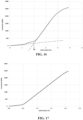
- the structural elongation As a quantity well known to those skilled in the art, is determined for example by applying the ASTM D2969-04 standard of 2014 to a cable tested so as to obtain a force-elongation curve.
- the As is deduced on the curve obtained as the elongation, in %, corresponding to the projection on the elongation axis of the intersection between the tangent to the structural part of the force-elongation curve and the tangent to the part elasticity of the force-elongation curve.
- an elongation force curve includes, moving towards increasing elongations, a structural part, an elastic part and a plastic part.
- the structural part corresponds to a structural elongation of the cable resulting from the bringing together of the various metallic wire elements constituting the cable.
- the layer of N metallic wire elements breaks down at the end of the structural part, due to the relatively small relative radial clearance Jr, causing a temporary increase in the modulus of the cable.
- the elastic part corresponds to an elastic elongation resulting from the construction of the cable, in particular the angles of the various layers and the diameters of the wires.
- the plastic part corresponds to the elongation plastic resulting from the plasticity (irreversible deformation beyond the elastic limit) of one or more metal wire elements.
- the helix diameter Dh corresponds to the diameter of the theoretical circle passing through the centers of the metallic wire elements of the layer in a plane perpendicular to the axis of the cable.
- the diameter or apparent diameter, denoted D is measured by means of a thickness comparator whose diameter of the keys is at least equal to 1.5 times the pitch P of winding of the wire elements (one can cite for example the model JD50 of the KAEFER brand allowing an accuracy of 1/100 of a millimeter to be achieved, equipped with a type a key, and having a contact pressure close to 0.6N).
- the measurement protocol consists of three repetitions of a series of three measurements (carried out perpendicular to the axis of the cable and under zero tension) of which the second and third of these measurements are carried out in a direction angularly offset from the previous one by a third of a turn, by the rotation of the direction of measurement around the axis of the cable.
- the pitch at which each metal wire element is wound is the length traveled by this wire element, measured parallel to the axis of the cable in which it is located, at the end of which the wire element having this pitch performs a complete turn around said axis of the cable.
- all the metallic wire elements have the same diameter Df.
- any interval of values designated by the expression “between a and b” represents the range of values going from more than a to less than b (i.e. limits a and b excluded) while any interval of values designated by the expression “from a to b” means the range of values going from a to b (that is to say including the strict limits a and b).
- radial section or radial section here is meant a section or a section along a plane which comprises the axis of rotation of the tire.
- axial direction is meant the direction substantially parallel to the axis of rotation of the tire.
- circumferential direction is meant the direction which is substantially perpendicular both to the axial direction and to a radius of the tire (in other words, tangent to a circle whose center is on the axis of rotation of the tire).
- radial direction is meant the direction along a radius of the tire, that is to say any direction intersecting the axis of rotation of the tire and substantially perpendicular to this axis.
- the median plane (denoted M) is the plane perpendicular to the axis of rotation of the tire which is located halfway between the two beads and passes through the middle of the crown reinforcement.
- the equatorial circumferential plane (denoted E) of the tire is the theoretical plane passing through the equator of the tire, perpendicular to the median plane and to the radial direction.
- the equator of the tire is, in a plane of circumferential section (plane perpendicular to the circumferential direction and parallel to the radial and axial directions), the axis parallel to the axis of rotation of the tire and located equidistant between the point radially outermost point of the tread intended to be in contact with the ground and the radially innermost point of the tire intended to be in contact with a support, for example a rim, the distance between these two points being equal to H.
- orientation of an angle we mean the direction, clockwise or anti-clockwise, in which it is necessary to turn from a reference straight line, here the circumferential direction of the pneumatic, defining the angle to reach the other line defining the angle.
- 0.14 ⁇ Jr ⁇ 0.25.
- a cable intended for the reinforcement of a tire for passenger vehicles but also for two-wheeled vehicles such as motorcycles, and preferably for passenger vehicles, we have 12 ⁇ Rf/Df ⁇ 30 , preferably 12 ⁇ Rf/Df ⁇ 25 and more preferably 12 ⁇ Rf/Df ⁇ 22.
- a cable intended for the reinforcement of a tire for passenger vehicles but also for two-wheeled vehicles such as motorcycles, and preferably for passenger vehicles, we have 1.70 ⁇ Dv/Df ⁇ 3.20.
- the helix radius of curvature Rf is such that 4.10 mm ⁇ Rf ⁇ 5.30 mm.
- a cable intended for the reinforcement of a tire for passenger vehicles but also for two-wheeled vehicles such as motorcycles, and preferably for passenger vehicles, we have 4.10 mm ⁇ Rf ⁇ 4.25mm.
- the helix diameter Dh of each metal wire element is such that 0.70 mm ⁇ Dh ⁇ 1.60 mm, preferably 0.75 mm ⁇ Dh ⁇ 1.60 mm and more preferably 0.80 mm ⁇ Dh ⁇ 1.60mm.
- a cable intended for the reinforcement of a tire for passenger vehicles but also for two-wheeled vehicles such as motorcycles, and preferably for passenger vehicles, we have 0.70 mm ⁇ Dh ⁇ 0.90 mm, preferably 0.75 mm ⁇ Dh ⁇ 0 .90 mm and more preferably 0.80 mm ⁇ Dh ⁇ 0.90 mm.
- a cable intended for the reinforcement of a tire for industrial vehicles chosen from vans, "Heavyweight", for example metro, bus, road transport vehicles (trucks, tractors, trailers), we have a 0.85 mm ⁇ Dh ⁇ 1.60 mm, preferably 1.15 mm ⁇ Dh ⁇ 1.60 mm and more preferably 1.20 mm ⁇ Dh ⁇ 1.60 mm.
- Df is such that 0.10 mm ⁇ Df ⁇ 0.50 mm, preferably 0.15 mm ⁇ Df ⁇ 0.50 mm and more preferably 0.15 mm ⁇ Df ⁇ 0.45 mm.
- a cable intended for the reinforcement of a tire for passenger vehicles but also for two-wheeled vehicles such as motorcycles, and preferably for passenger vehicles, we have 0.15 mm ⁇ Df ⁇ 0.35mm.
- Dv is such that Dv ⁇ 0.50 mm and more preferably 0.50 mm ⁇ Dv ⁇ 1.20 mm.
- a cable intended for the reinforcement of a tire for passenger vehicles but also for two-wheeled vehicles such as motorcycles, and preferably for passenger vehicles, we have 0.50 mm ⁇ Dv ⁇ 0.70 mm and preferably 0.50 mm ⁇ Dv ⁇ 0.65 mm.
- each metallic wire element is wound at a pitch P such that 3 mm ⁇ P ⁇ 15 mm, preferably 5 mm ⁇ P ⁇ 13 mm and more preferably 7 mm ⁇ P ⁇ 11 mm.
- a cable intended for the reinforcement of a tire for passenger vehicles but also for two-wheeled vehicles such as motorcycles, and preferably for passenger vehicles, we have 7 mm ⁇ P ⁇ 8, 5 mm.
- D is such that D ⁇ 2.10 mm, preferably 0.90 mm ⁇ D ⁇ 2.10 mm, 0.95 mm ⁇ D ⁇ 2.05 mm.
- a cable intended for the reinforcement of a tire for passenger vehicles but also for two-wheeled vehicles such as motorcycles, and preferably for passenger vehicles, we have 0.95 mm ⁇ D ⁇ 1.20mm.
- each metal wireframe includes a single metal monofilament.
- each metallic wire element advantageously consists of a metallic monofilament.
- the metallic monofilament is directly coated with a layer of a metallic coating comprising copper, zinc, tin, cobalt or an alloy of these metals, for example brass or the bronze.
- each metal wire element then consists of the metal monofilament, for example steel, forming a core, directly coated with the metal coating layer.
- each metallic elementary monofilament is, as described above, preferably made of steel, and has a mechanical strength ranging from 1000 MPa to 5000 MPa.
- Such mechanical strengths correspond to the steel grades commonly encountered in the field of tires, namely, NT (Normal Tensile), HT (High Tensile), ST (Super Tensile), SHT (Super High Tensile), UT ( Ultra Tensile), UHT (Ultra High Tensile) and MT (Mega Tensile), the use of high mechanical strength possibly allowing improved reinforcement of the matrix in which the cable is intended to be embedded and a lightening of the matrix thus reinforced.
- the layer being made up of N metal wire elements wound in a helix N ranges from 3 to 18, preferably from 5 to 12 and more preferably from 6 to 9.
- the ratio K of the pitch P to the diameter Df of each element metal wire, P and Df being expressed in millimeters is such that 19 ⁇ K ⁇ 44, preferably 20 ⁇ K ⁇ 40 and more preferably 23 ⁇ K ⁇ 39.
- a cable intended for the reinforcement of a tire for passenger vehicles but also for two-wheeled vehicles such as motorcycles, and preferably for passenger vehicles, we have 23 ⁇ K ⁇ 40 and preferably 25 ⁇ K ⁇ 39.
- the helix angle ⁇ of each metal wire element is such that 13° ⁇ 30°, preferably 17° ⁇ 26°.
- the longitudinal compressibility of the cable is reduced.
- the longitudinal stiffness of the cable and therefore its capacity for reinforcement are reduced. Thanks to the invention, it is nevertheless possible to use relatively high values of the angle ⁇ thanks to the relatively low relative radial play Jr and therefore to the presence of a relatively high number of metallic wire elements on the layer.
- a cable intended for the reinforcement of a tire for passenger vehicles but also for two-wheeled vehicles such as motorcycles, and preferably for passenger vehicles, we have 13° ⁇ ⁇ ⁇ 19, 5° and preferably 17° ⁇ 19.5°.
- a cable intended for the reinforcement of a tire for industrial vehicles chosen from vans, "Heavyweight", for example metro, bus, road transport vehicles (trucks, tractors, trailers), there are 18 .5° ⁇ 30° and preferably 18.5° ⁇ 26°.
- the cable has a structural elongation As such that As ⁇ 1.5%, preferably such as 1.5% ⁇ As ⁇ 5.0% and more preferably such as 1.9% ⁇ As ⁇ 4.5%, the structural elongation As being determined by applying the standard ASTM D2969-04 of 2014 to the cable so as to obtain a force-elongation curve, the structural elongation As being equal to the elongation, in %, corresponding to the projection on the elongation axis of the intersection between the tangent to the structural part of the force-elongation curve and the tangent to the elastic part of the force-elongation curve.
- the cable according to the invention has a bi-module force-elongation curve.
- the force-elongation curve has on the one hand a structural part characterized in particular by an elastic modulus in extension of this structural part and, on the other hand, an elastic part characterized in particular by an elastic modulus in extension of this elastic part.
- the cable has an elastic modulus in extension of the structural part of less than or equal to 15 GPa, preferably ranging from 2 GPa to 15 GPa.
- the cable has a relatively low modulus which is equivalent to that of so-called extensible or elastic cables of the state of the art having a moderate structural elongation ranging from 1% to 2.5%.
- the cable has an elastic modulus in extension of the elastic part greater than or equal to 50 GPa, preferably ranging from 50 to 180 GPa.
- the cable has a relatively high modulus which is equivalent to so-called inextensible cables of the state of the art having, unlike the advantageous cables of the invention, a relatively low As of less than 1%.
- the cables have relatively low moduli, the elastic modulus in extension of the elastic part then ranging from 80 to 130 GPa. In another embodiment in which the cables have higher moduli, the elastic modulus in extension of the elastic part ranges from 130 to 180 GPa.
- the elastic modulus in extension of the structural part of the cable is measured by applying the standard ASTM D2969-04 of 2014 to a cable tested in order to obtain a stress-elongation curve.
- the elastic modulus in extension of the structural part is deduced from the curve obtained as the slope of the structural part of the stress-elongation curve.
- the elastic modulus in extension of the elastic part of the cable is measured by applying the standard ASTM D2969-04 of 2014 to a tested cable in order to obtain a stress-elongation curve.
- the elastic modulus in extension is deduced on the curve obtained as the slope of the elastic part of the stress-elongation curve.
- the cable once embedded in a standard cross-linked elastomeric matrix having a tensile modulus at 10% elongation ranging from 5 MPa to 10 MPa, has an elastic tensile modulus greater than or equal to 100 GPa, preferably ranging from 100 GPa to 180 GPa, more preferentially from 110 GPa to 180 GPa and even more preferentially from 120 GPa to 180 GPa, the elastic modulus in extension at 10% elongation being determined according to standard ASTM D2969-04 of 2014.
- the elastic modulus in extension ranges from 100 GPa to 130 GPa. In another embodiment in which the cables have higher moduli, the elastic modulus in extension ranges from 130 GPa to 180 GPa.
- the elastic modulus in extension of the cable embedded in the standard cross-linked elastomeric matrix is measured by applying the ASTM D2969-04 standard of 2014 to this cable embedded in the standard cross-linked elastomeric matrix tested so as to obtain a stress-elongation curve.
- the elastic modulus in extension is deduced on the curve obtained as the slope of the elastic part of the stress-elongation curve.
- the nominal secant modulus in extension at 10% elongation or modulus in extension at 10% elongation is measured in the second elongation (i.e., after an accommodation cycle at the rate of extension planned for the measurement itself). These tensile tests make it possible to determine the elasticity stresses and the breaking properties. They are carried out in accordance with the French standard NF T 46-002 of September 1988. We measure in second elongation (i.e., after an accommodation cycle at the rate of extension provided for the measurement itself) the nominal secant modulus in extension (or apparent stress, in MPa) at 10% elongation (denoted MA 10) at 23°C ⁇ 2°C, and under normal hygrometric conditions.
- the standard elastomeric matrix is obtained by curing at 160° C. for 15 minutes an elastomeric composition based on natural rubber, carbon black and usual additives.
- the elastomeric composition comprises 100 phr of natural rubber, 50 phr of 300 series carbon black, 1.5 of N-1,3-dimethylbutyl-N-phenyl-para-phenylenediamine, 1 phr of a of cobalt, and a crosslinking system comprising 0.9 phr of stearic acid, 6 phr of insoluble molecular sulfur, 0.8 phr of N,N'-dicyclohexyl-2-benzothiazole-sulfenamide and 7.5 phr of ZnO and having, at the end of the firing step, a nominal secant modulus in extension at 10% elongation equal to 6 MPa.
- each metal wire element is devoid of preformation marks.
- preformation marks include in particular flats.
- the preformation marks also include cracks extending in section planes substantially perpendicular to the main axis along which each metallic wire element extends. Such cracks extend, in a section plane substantially perpendicular to the main axis, from a radially outer surface of each metal wire element radially towards the inside of each metal wire element.
- cracks are initiated by mechanical preforming tools due to bending stresses, i.e. perpendicular to the main axis of each metallic wired element, which makes them very detrimental to stamina.
- the metal wire elements are preformed collectively and simultaneously on the transient core and the preformation forces are exerted in torsion and therefore not perpendicular to the main axis of each metal wire element. Any cracks created do not extend radially from the radially outer surface of each metal wire element radially towards the inside of each metal wire element but along the radially outer surface of each metal wire element which makes them not very harmful for endurance.
- the first assembly, the second assembly and the transient core being isolated from any other metallic wire element resulting from the layer constituted of M′>1 metallic wire elements.
- the first assembly, the second assembly and an assembly constituted by the transient core At the end of the step of separating the transient assembly, one obtains, in a variant, the first assembly, the second assembly and an assembly constituted by the transient core.
- the assembly comprising the transient core also comprising one or more elements metal wireframes from the layer consisting of M′>1 metal wireframe elements of the transient assembly.
- the first assembly, the second assembly and an assembly consisting of the transient core and one or more several metal wire elements from the layer consisting of M′>1 metal wire elements are obtained at the end of the step of separating the transient assembly.
- the first assembly, the second assembly and several assemblies each comprising a part of the transient core are obtained, each set comprising a part of the transient core comprising also one or more metal wire elements from the layer consisting of M′>1 metal wire elements of the transient assembly.
- the sets comprise the entire transient core and the parts of the transient core of the sets form the transient core in its entirety.
- the first assembly, the second assembly and several assemblies are obtained, each consisting of a part of the transient core and one or more metal wire elements from the layer consisting of M′>1 wire elements of the transient assembly, the parts of the transient core constituting the transient core.
- the step of reassembling the method it is possible, for given geometric characteristics, to increase the linear mass of the cable according to the invention compared to the method of the state of the art in which the number of elements metal wires is necessarily limited, this while allowing the output of the transient core. Conversely, for a given linear mass, it is possible to obtain a greater range of geometric characteristics than with the method of the state of the art.
- the metal wire element(s) M1′ wound in a helix forming the layer of the first split assembly is reassembled with the metal wire element(s) M2′ wound in a helix forming the layer of the second split assembly.
- the reassembly of the metallic wire elements of these two layers makes it possible to obtain the layer of the cable according to the invention.
- the reassembly step makes it possible to form the cable according to the invention in which the N metal wire elements have the same geometric properties and therefore form a homogeneous layer of metal wire elements.
- the supply step, the separation step and the reassembly step are carried out so that all the N elements metal wires have the same diameter Df, are wound in a helix according to the same pitch P and have the same helix diameter Dh.
- the transient assembly of the method making it possible to manufacture the cable according to the invention consists of the layer formed by the M′ metal wire elements and of the transient core, the M′ metal wire elements being wound in a helix around the transient core.
- the method for manufacturing the cable according to the invention is advantageously a continuous or in-line method.
- a step of splitting an initial object into several final objects means that, during this splitting step, the initial object is divided into the final objects and only these final objects so that the initial object is found fully in the final objects. Moreover, in a splitting step, the initial object is divided into the final objects simultaneously, that is to say that the final objects are separated at the same splitting point. In particular, in the case of an initial object split into at least three final objects, the three final objects are, during a splitting step, separated simultaneously from each other and at the same point.
- a step of separating an initial object between several final objects means that, to obtain these final objects, at least one splitting step is necessary.
- the separation step comprises a step of splitting the initial object into the final objects or else comprises a step of splitting the initial object into intermediate objects followed by one or more successive steps splitting intermediate objects into final objects.
- the initial object is not necessarily found entirely in the final objects, sets or assemblies having been extracted from the process during one or more splitting steps and not used during subsequent fractionation steps.
- a separation step can comprise one or more steps of reassembly between several intermediate objects resulting from a splitting step of the separation step to obtain other intermediate objects or else the final objects.
- the final objects are physically separated from each other, i.e. not in contact with each other downstream of the stage and upstream of any step of reassembling two or more of these final objects.
- the cable according to the invention has a single helix.
- a single helix assembly is an assembly in which the axis of each metal wire element describes a single helix, unlike a double helix assembly in which the axis of each metal wire element describes a first helix around the axis of the assembly and a second helix around a helix described by the axis of the assembly.
- each metallic wire element of the or each layer when the assembly extends in a substantially rectilinear direction, the assembly comprising one or more layers of helically wound wire elements, each metallic wire element of the or each layer describes a path in the shape of a helix around the substantially rectilinear direction so that the distance between the center of each metallic wire element of a given layer and the axis of the substantially rectilinear direction is substantially constant and equal for all the metallic wire elements of each given layer .
- the distance between the center of each metal wire element of a given layer and the substantially rectilinear direction is different for all the metal wire elements of the layer. given.
- the separation step and the reassembly step are carried out so that M1′+M2′ ⁇ M′.
- the precursor assembly is made up of a layer made up of M1" metallic wire elements wound in a helix
- the main assembly is made up of a layer made up of the M3 metal wire element(s) wound helically
- the complementary assembly consists of a layer consisting of the M3′ metal wire element(s) wound( s) helically.
- the step of separating the transient assembly between the precursor assembly, the second split assembly and the transient core or one or more assemblies comprising the transient core, preferably the transient core has place upstream of the stage of separation of the precursor assembly between the main and complementary assemblies.
- the split assembly consists of the layer formed by the M4' metal wire elements and of the transient core, the M4' metal wire elements being wound helically around the transient core.
- the step of separating the fractionated assembly between the precursor assembly and the transitional core or one or more assemblies comprising the transitional core, preferably the transitional core takes place upstream of the separation stage of the precursor set between the main and complementary sets.
- M4′ M1′′ in the case of a step of splitting the fractionated assembly between the precursor assembly and the transitional core.
- the split assembly consists of the layer formed by the M4' metal wire elements and of the transient core, the M4' metal wire elements being wound helically around the transient core.
- the step of separating the transient assembly between the split assembly and the precursor assembly takes place upstream of the step of separating the split assembly between the second split assembly and the transient core or one or more assemblies comprising the transient core, preferably the transient core.
- M4′ M2′ in the case of a step of splitting the split assembly into the second split assembly and the transitional core.
- the split assembly consists of the layer formed by the M4' metal wire elements and of the transient core, the M4' metal wire elements being wound helically around the transient core .
- the step of separating the transient assembly between the split assembly and the second split assembly takes place upstream of the step of separating the split assembly between the first split assembly and the transient core or one or more assemblies comprising the transient core, preferably the transient core.
- the main assembly is made up of a layer made up of the metal wire element(s) M3 wound in a helix and the complementary assembly is made up of a layer consisting of one or more M3' metallic wire element(s) wound in a helix.
- the derived assembly consists of the layer consisting of the M5′ ⁇ 1 element(s) wired metal(s) wound(s) and of the transient core, the M5′ element(s) metal wire(s) being wound helically around the transient core.
- the step of separating the fractionated set between the main set and the derived set takes place upstream of the step of separating the derived set between the complementary set and the transitional core or one or more assemblies comprising the transient core, preferably the transient core.
- M5′ M3′ in the case of a step of splitting the derived set into the complementary set and the transient core.
- the split assembly consists of the layer consisting of the metal wire element(s) M4' (s).
- the first split assembly consists of the layer constituted by the M6' metal wire elements and the first part of the transient core, the M6' metal wire elements being helically wound around the first part of the transient core.
- the second split assembly consists of the layer formed by the M7' metal wire elements and the second part of the transitional core, the M7' metal wire elements being wound helically around the second part of the transitional core.
- the step of separating the transient assembly between the first split assembly and the second split assembly takes place upstream of the step of separating the first split assembly between the first split assembly and the first transitional core part or one or more sets comprising the first transitional core part, preferably the first transitional core part.
- the step of separating the transient assembly between the first split assembly and the second split assembly takes place upstream of the step of separating the second split assembly between the second split assembly, and the second part of the transient core or one or more assemblies comprising the second part of the transient core, preferably the second part of the transient core.
- the main assembly is made up of a layer made up of the metal wire element(s) M3 wound in a helix and the complementary assembly is made up of a layer consisting of one or more M3' metallic wire element(s) wound in a helix.
- the precursor assembly consists of a layer consisting of M1′′ metal wire elements wound in a helix.
- the step of separating the first split assembly between the precursor assembly and the first part of the transitional core or one or more assemblies comprising the first part of the transitional core, preferably the first part of the transitional core takes place upstream of the stage of separation of the precursor assembly between the main assembly forming the first split assembly and the complementary assembly.
- M6′ M1′′ in the case of a step of splitting the first set split into the precursor set and the first part of the transitional core.
- the derived assembly consists of the layer consisting of the M5′ ⁇ 1 metal wire element(s) and the first part of the core transient, the metal wire element(s) M5' ⁇ 1(s) being wound helically around the first part of the transient core.
- the step of separating the first set split between the main set and the derived set takes place upstream of the step of separating the derived set between the complementary assembly and the first part of the transitional core or one or more assemblies comprising the first part of the transitional core, preferably the first part of the transitional core.
- M5′ M3′ in the case of a step of splitting the derived set into the complementary set and the first part of the transient core.
- the split assembly consists of the layer consisting of the metal wire element(s) M4' (s).
- the split assembly consists of the layer formed by the metallic wire element(s) M4' and the transient core, the metallic element(s) M4' (s) metal wire(s) being helically wound around the transient core.
- the step of separating the transient assembly between the split assembly and the second split assembly takes place upstream of the step of separating the split assembly between the first assembly split and the transient core or one or more assemblies comprising the transient core, preferably the transient core.
- the split assembly consists of the layer formed by the M4' metal wire elements and of the transitional core, the metal wire elements being wound helically around the transient core.
- the step of separating the transient assembly between the split assembly and the first split assembly takes place upstream of the step of separating the split assembly between the second assembly split and the transient core or one or more assemblies comprising the transient core, preferably the transient core.
- M' M6'+M7'
- M6' M1'
- M7' M2'.
- the first split assembly is made up of the layer made up of the metallic wire element(s) M6' and the first part of the transient core, the M6' metallic wire element(s) being wound helically around the first part of the transient core.
- the second split assembly consists of the layer consisting of the M7' metal wire elements and the second part of the transitional core, the M7' metal wire elements being wound helically around the second part of the transient core.
- the step of separating the transient assembly between the first split assembly and the second split assembly takes place upstream of the step of separating the first split assembly between the first split assembly and the first part of transient core.
- the step of separating the transient assembly between the first split assembly and the second split assembly takes place upstream of the step of separating the second split assembly between the second split assembly and the second part of the transitional kernel.
- M' ranges from 4 to 18 and preferably from 6 to 9.
- the step of supplying the transient assembly comprises a step of assembly by twisting of the M′>1 metal wire elements wound in a helix around the transient core.
- the step of supplying the transient assembly includes a step of balancing the transient assembly.
- the balancing step being carried out on the transient assembly comprising the M′ metal wire elements and the transient core, the balancing step is implicitly carried out upstream of the separation step between the first and second split assemblies.
- the method includes a step of balancing the cable according to the invention downstream of the reassembly step.
- the method comprises a step of maintaining the rotation of the cable according to the invention around its respective running direction.
- This step of maintaining the rotation is carried out downstream of the step of separating the transient assembly and upstream of the step of balancing the cable according to the invention.
- the method is devoid of individual preforming steps for each of the metallic wire elements.
- the latter are given a shape imposed by preforming tools, for example rollers, these tools creating defects on the surface of the metal wireframe elements. These defects significantly reduce the endurance of the metallic wire elements and therefore of the cable according to the invention.
- the supply means, the separation means and the reassembly means are arranged so that all the N metal wire elements have the same diameter Df, are helically wound with the same pitch P and have the same helix diameter Dh.
- means for splitting an initial object into several final objects means that, by implementing these splitting means, the initial object is divided into the final objects and only these final objects so that the initial object is found entirely in the final objects. Moreover, by using splitting means, the initial object is divided into the final objects simultaneously, that is to say the final objects are separated at the same splitting point. In particular, in the case of an initial object split into at least three final objects, the three final objects are, by using splitting means, separated simultaneously from each other and at the same point.
- means for separating an initial object between several final objects mean that, in order to obtain these final objects, at least splitting means are necessary.
- the separation means comprise means for splitting the initial object into the final objects or else comprise means for splitting the initial object into intermediate objects and means for splitting the intermediate objects into the final objects.
- the separation means By using the separation means, the initial object is not necessarily found entirely in the final objects, sets or assemblies having been able to be extracted from the process during their passage through the splitting means and not used during their passage through subsequent splitting means.
- means of separation can comprise means of reassembly between several intermediate objects resulting from means of splitting the means of separation to obtain other intermediate objects or else the final objects.
- the separation means and the reassembly means are arranged so that M1'+M2' ⁇ M'.
- the means for separating the transient assembly between the precursor assembly, the second split assembly and the transient core or one or more assemblies comprising the transient core, preferably the transient core are arranged upstream means for separating the precursor assembly between the main and complementary assemblies.
- the means for separating the fractionated assembly between the precursor assembly and the transient core or one or more assemblies comprising the transient core, preferably the transient core are arranged upstream of the means for separating the precursor set between the main and complementary sets.
- the means for separating the transient assembly between the split assembly and the precursor assembly are arranged upstream of the means for separating the split assembly between the second split assembly and the transitional core or one or more assemblies comprising the transient core, preferably the transient core.
- the means for separating the transient assembly between the split assembly and the second split assembly are arranged upstream of the means for separating the split assembly between the first split assembly and the transitional core or one or more assemblies comprising the transient core, preferably the transient core.
- the means for separating the split assembly between the main assembly and the derivative assembly are arranged upstream of the means for separating the derivative assembly between the complementary assembly and the transitional core or one or more assemblies comprising the transient core, preferably the transient core.
- the means for separating the transitional assembly between the first split assembly and the second split assembly are arranged upstream of the means for separating the first split assembly between the first split assembly and the first part of the transient core or one or more assemblies comprising the first part of the transient core, preferably the first part of the transient core,.
- the means for separating the transient assembly between the first split assembly and the second split assembly are arranged upstream of the means for separating the second split assembly between the second split assembly, and the second part of the transient core or one or more assemblies comprising the second part of the transient core, preferably the second part of the transient core.
- the means for separating the first split assembly between the precursor assembly and the first part of the transitional core or one or more assemblies comprising the first part of the transitional core, preferably the first part of the transient core are arranged upstream of the means for separating the precursor assembly between the main assembly forming the first split assembly and the complementary assembly.
- the means for separating the first split assembly between the main assembly and the derivative assembly are arranged upstream of the means for separating the derivative assembly between the complementary assembly and the first part of the transient core or one or more assemblies comprising the first part of the transient core, preferably the first part of the transient core.
- the means for separating the transient assembly between the split assembly and the second split assembly are arranged upstream of the means for separating the split assembly between the first split assembly and the transient core.
- the means for separating the transient assembly between the split assembly and the second split assembly comprise means for splitting the transient assembly between the split assembly and the second split assembly.
- the means for separating the transient assembly between the split assembly and the first split assembly are arranged upstream of the means for separating the split assembly between the second split assembly and the transient core.
- the means for separating the transitional assembly between the first split assembly and the second split assembly are arranged upstream of the means for separating the first split assembly between the first split assembly and the first part of the transient core.
- the means for separating the transient assembly between the first split assembly and the second split assembly are arranged upstream of the means for separating the second split assembly between the second split assembly and the second part of the transient core.
- the means for separating the transient assembly between the first split assembly and the second split assembly comprise means for splitting the transient assembly into the first split assembly and the second split set.
- the means for supplying the transient assembly comprise means for assembling by twisting the M′>1 metallic wire elements wound in a helix around the transient core.
- the means for supplying the transient assembly comprise means for balancing the transient assembly.
- the reassembly step respectively the reassembly means may allow the reassembly of more than the first and second split assemblies, for example the reassembly of three or even four split assemblies.
- the invention also relates to the use of such a cable for reinforcing articles or semi-finished products comprising an elastomeric matrix in which the cable is embedded.
- Such articles or semi-finished products are pipes, belts, conveyor belts, caterpillars, tires for vehicles, both in the raw state (that is to say before cross-linking or vulcanization) and in the cured state (after cross-linking or vulcanization).
- Such articles or semi-finished products take, in preferred modes, the form of a web.
- the invention also relates to an article or semi-finished product comprising an elastomeric matrix in which is embedded at least one cable as defined above.
- Another object of the invention is the use of a cord as defined above for reinforcing a tire comprising the cord.
- the invention also relates to a tire comprising a cable as defined previously embedded in an elastomeric matrix, in other words a tire comprising a reinforcing wire element obtained by embedding a cable as defined above in an elastomeric matrix.
- tire is meant a tire intended to form a cavity by cooperating with a support element, for example a rim, this cavity being capable of being pressurized to a pressure greater than atmospheric pressure.
- a tire according to the invention has a structure of substantially toroidal shape.
- the cable is embedded in the elastomeric matrix.
- the cable comprises a material for filling the internal arch based on an elastomeric composition and located in the internal arch of the filled cable.
- the filling material here is based on the same elastomeric composition as that based on the elastomeric matrix in which the cable is embedded.
- the values of the characteristics D, Df, Dv, Rf and ⁇ as well as of the other characteristics described above are measured on or determined from plies and cords extracted from a tire.
- the characteristics of the cord described above ensure that, at the end of the tire manufacturing process, taking into account the shaping step, the tire will have the advantages described above.
- elastomeric matrix a matrix with elastomeric behavior resulting from the crosslinking of an elastomeric composition.
- the elastomeric matrix is thus based on the elastomeric composition.
- the filling material is based on an elastomeric composition, here the same composition as that of the matrix in which the cable is embedded.
- composition comprises the mixture and/or the in situ reaction product of the various constituents used, some of these constituents being able to react and/or being intended to react with one another, less partially, during the various phases of manufacture of the composition; the composition thus possibly being in the totally or partially crosslinked state or in the non-crosslinked state.
- elastomeric composition it is meant that the composition comprises at least one elastomer and at least one other component.
- the composition comprising at least one elastomer and at least one other component comprises an elastomer, a crosslinking system and a filler.
- the compositions used for these sheets are conventional compositions for calendering filamentary reinforcing elements, comprise a diene elastomer, for example natural rubber, a reinforcing filler, for example carbon black and/or silica, a crosslinking, for example a vulcanization system, preferably comprising sulfur, stearic acid and zinc oxide, and optionally a vulcanization accelerator and/or retarder and/or various additives.
- the adhesion between the reinforcing wire elements and the matrix in which they are embedded is ensured for example by a usual adhesive composition, for example an adhesive of the RFL type or equivalent adhesive.
- the secant tensile modulus of a sheet for a force equal to 15% of the breaking force is denoted MA 15 and is expressed in daN/mm.
- the MA 15 modulus is calculated from a force-elongation curve obtained by applying the ASTM D2969-04 standard of 2014 to a cord of the sheet.
- the secant modulus in tension of the cable is calculated by determining the slope of the line drawn between the points (0,0) and the point of the curve having an ordinate equal to 15% of the breaking force.
- the modulus MA 15 is determined by multiplying the tensile secant modulus of the cable by the density of cables per mm of layer.
- the density d of reinforcing wire elements in a ply is the number of reinforcing wire elements present in the ply in a direction perpendicular to the direction in which the reinforcing wire elements extend in the ply.
- the density d can also be determined from the laying pitch p expressed in mm, the laying pitch being equal to the axis-to-axis distance between two consecutive reinforcing wire elements in the direction perpendicular to the direction in which the reinforcing elements extend into the web.
- the breaking force of a cable is measured according to the ASTM D2969-04 standard of 2014.
- the breaking force of a sheet is calculated from a force-elongation curve obtained by applying the ASTM D2969-04 standard of 2014 to a cable from the tablecloth.
- the breaking force of the ply is determined by multiplying the breaking force of the cord by the density of cords per unit width of the ply, this density being as defined above.
- the tires of the invention may be intended for passenger motor vehicles (including in particular 4x4 vehicles and "SUVs" (Sport Utility Vehicles)), but also for two-wheeled vehicles such as motorcycles, or for vehicles industrial vehicles chosen from vans, "Heavyweight” - i.e., metro, bus, road transport vehicles (trucks, tractors, trailers).
- passenger motor vehicles including in particular 4x4 vehicles and "SUVs” (Sport Utility Vehicles)
- SUVs Sport Utility Vehicles
- two-wheeled vehicles such as motorcycles
- industrial vehicles chosen from vans, "Heavyweight” - i.e., metro, bus, road transport vehicles (trucks, tractors, trailers).
- trucks trucks, tractors, trailers
- the tires of the invention are intended for passenger vehicles.
- the tire comprises a crown comprising a tread and a crown reinforcement, two sidewalls, two beads, each sidewall connecting each bead to the crown, the crown reinforcement extending into the crown in a circumferential direction of the tire, the tire comprising a carcass reinforcement anchored in each of the beads and extending in the sidewalls and in the crown, the crown reinforcement being radially interposed between the carcass and the tread, the crown reinforcement comprising a reinforcing wire element obtained by embedding a cable as defined above in an elastomeric matrix.
- the crown reinforcement comprises a hooping reinforcement comprising at least one hooping ply and preferably a single hooping ply.
- the hooping reinforcement preferably consists of a hooping layer.
- This embodiment is particularly suitable for a tire for passenger vehicles, two-wheeled vehicles, industrial vehicles chosen from vans, "heavy goods vehicles", for example metros, buses, road transport vehicles (trucks, tractors, trailers), and preferably for passenger vehicles.
- the crown reinforcement comprises a working reinforcement comprising at least one working ply.
- the hooping reinforcement is radially interposed between the working reinforcement and the tread.
- the hooping reinforcement exerts, in addition to its hooping function, a function of protection against perforations and shocks much more effective than a hooping reinforcement comprising wire elements of textile hooping reinforcement.
- the hooping ply comprises at least one hooping reinforcing wire element obtained by embedding a cable as defined above in an elastomeric matrix.
- the cable makes it possible to reduce the thicknesses of the hooping ply, the mass of the latter, the hysteresis of the tire and therefore the rolling resistance of the tire. Indeed, all other things being equal, the greater the thickness of the hooping ply, the higher the hysteresis of the latter.
- the diameter By reducing the diameter, the total thickness of the ply is reduced while maintaining the thickness present on the back of each cable, which makes it possible to maintain the decoupling thicknesses between, on the one hand, the tread and the ply of hooping, and on the other hand, the plies radially inside the hooping ply and the hooping ply.
- the cable makes it possible to give the tire excellent endurance in compression, and this is all the more advantageous in the case of the elimination of a working ply compared to a tire of the state of the art described in US2007006957 .
- the hooping reinforcement is, due to the use of metal wire elements, less expensive, more thermally stable and provides mechanical protection to the tire.
- the use of metallic wire elements makes it easier to check the hooping reinforcement by radiography after its manufacture.
- the cord of the tire according to the invention has excellent longitudinal compressibility and therefore much greater compression endurance.
- the hooping reinforcement exerts, in addition to its hooping function, a function of protection against perforations and shocks much more effective than a hooping reinforcement comprising wire elements of textile hooping reinforcement.
- the or each hooping reinforcing wire element makes an angle strictly less than 10°, preferably less than or equal to 7°, and more preferably less than or equal to 5° with the circumferential direction of the tire.
- each working ply comprises several working reinforcing wire elements.
- each working reinforcing wire element is a metallic wire element.
- each wired working reinforcement element of each ply are arranged side by side substantially parallel to each other. More preferably, each wired working reinforcement element extends axially from one axial end of the working reinforcement of the tire to the other axial end of the working reinforcement of the tire.
- the carcass reinforcement comprises at least one carcass ply and more preferably a single carcass ply.
- the carcass reinforcement is more preferably, with the exception of the carcass ply, devoid of any ply reinforced by wire reinforcement elements.
- the wire-like reinforcing elements of such reinforced plies excluded from the carcass reinforcement of the tire comprise metal wire-like reinforcing elements and textile wire-like reinforcing elements.
- the carcass reinforcement consists of a carcass ply. This embodiment is particularly suitable for a tire for passenger vehicles, two-wheeled vehicles, industrial vehicles chosen from vans, "heavy goods vehicles", for example metros, buses, road transport vehicles (trucks, tractors, trailers), and preferably for passenger vehicles.
- the carcass ply comprises corded carcass reinforcement elements.
- each carcass reinforcement wire element is a textile wire element.
- textile is understood to mean by definition a non-metallic wire element consisting of one or more elementary textile monofilaments optionally coated with one or more layers of a coating based on an adhesive composition.
- Each elementary textile monofilament is obtained, for example, by melt spinning, solution spinning or gel spinning.
- Each elementary textile monofilament is made of an organic, in particular polymeric, or inorganic material, such as for example glass or carbon.
- the polymeric materials can be of the thermoplastic type, such as for example aliphatic polyamides, in particular polyamides 6-6, and polyesters, in particular polyethylene terephthalate.
- the polymeric materials can be of the non-thermoplastic type, such as aromatic polyamides, in particular aramid, and cellulose, both natural and artificial, in particular rayon.
- each corded carcass reinforcement element extends axially from one bead of the tire to the other bead of the tire.
- At least the corded work reinforcement elements and the corded carcass reinforcement elements are arranged so as to define, in projection on an equatorial circumferential plane in the radial direction of the tire, a triangular mesh.
- the crown reinforcement consists of the working reinforcement and the hooping reinforcement.
- the crown reinforcement is, with the exception of the working reinforcement and the hooping reinforcement, devoid of any ply reinforced by wire reinforcement elements arranged substantially parallel to each other and embedded in a matrix of rubber composition.
- the wire-like reinforcing elements of such reinforced plies excluded from the crown reinforcement of the tire comprise metal wire-like reinforcing elements and textile wire-like reinforcing elements.
- the reinforcing wire elements of each ply are embedded in an elastomeric matrix.
- the different layers can comprise the same elastomeric matrix or else distinct elastomeric matrices.
- the strip of polymeric material consists of a ply of a polymeric material, preferably an elastomeric material, or else consists of a stack of several layers, each ply being composed of a polymeric material, preferably an elastomeric material.
- the crown reinforcement comprises a single hooping reinforcement and a single working reinforcement.
- the crown reinforcement is, with the exception of the hooping reinforcement and the working reinforcement, devoid of any reinforcement reinforced by reinforcing elements.
- the reinforcement elements of such reinforcements excluded from the crown reinforcement of the tire include wire reinforcement elements, knits or even fabrics.
- the crown reinforcement consists of the hooping reinforcement and the working reinforcement.
- the crown is, with the exception of the crown reinforcement, devoid of any reinforcement reinforced by reinforcing elements.
- the reinforcing elements of such reinforcements excluded from the crown of the tire include wire reinforcing elements, knits or even fabrics.
- the crown is formed by the tread and the crown reinforcement.
- the carcass reinforcement is arranged directly radially in contact with the crown reinforcement and the crown reinforcement is arranged directly radially in contact with the tread.
- the working reinforcement comprises a single working ply
- the single hooping ply and the single working ply are advantageously arranged directly radially in contact with one of the other.
- the working reinforcement comprises two working plies and preferably the working reinforcement consists of two working plies.
- the work reinforcement wire elements and the carcass reinforcement wire elements are arranged so as to define, in projection on an equatorial circumferential plane in the radial direction of the tire, a triangular mesh.
- the hooping reinforcing wire elements are not necessary to define the triangular mesh.
- each wired working reinforcement element of each working ply forms an angle ranging from 10° to 40°, preferably ranging from 20° to 30° with the circumferential direction of the tire.
- the orientation of the angle made by the wired work reinforcement elements with the circumferential direction of the tire in a work ply is opposite to the orientation of the angle made by the wired work reinforcement elements with the circumferential direction of the tire in the other working ply.
- the working reinforcement wire elements of one working ply are crossed with the working reinforcing wire elements of the other working ply.
- each corded carcass reinforcement element makes an angle greater than or equal to 80°, preferably ranging from 80° to 90° with the circumferential direction of the tire in the median plane of the tire, in other words in the crown of the tire.
- each corded carcass reinforcement element forms an angle greater than or equal to 80°, preferably ranging from 80° to 90° with the circumferential direction of the tire in the equatorial circumferential plane of the tire, in other words in each sidewall.
- the working reinforcement comprises a single working ply.
- the working reinforcement is, with the exception of the working ply, devoid of any ply reinforced by wire reinforcing elements.
- the wire-like reinforcing elements of such reinforced plies excluded from the working reinforcement of the tire comprise metal wire-like reinforcing elements and textile wire-like reinforcing elements.
- the working reinforcement is preferably constituted by a working ply.
- This embodiment is particularly advantageous when the or each hooping reinforcing wire element consists of a cable as defined above.
- the mechanical strength and endurance properties of the hooping reinforcement described above then make it possible to remove a working ply from the working reinforcement. A significantly lightened tire is obtained.
- the hooping reinforcement wire element(s), the working reinforcement wire elements and the carcass reinforcement wire elements are arranged so as to define, in projection on an equatorial circumferential plane in the radial direction of the tire, a triangular mesh.
- the hooping reinforcement wire elements are necessary to define the triangular mesh.
- each carcass reinforcement wire element forms an angle A C1 greater than or equal to 55°, preferably ranging from 55° to 80° and more preferably ranging from 60° to 70°, with the circumferential direction of the tire in the plane median of the tire, in other words in the crown of the tire.
- the carcass reinforcing wire elements by virtue of the angle formed with the circumferential direction, participate in the formation of the triangular mesh in the crown of the tire.
- each carcass reinforcing wire element forms an angle A C2 greater than or equal to 85° with the circumferential direction of the tire in the equatorial circumferential plane of the tire, in other words in each sidewall of the tire.
- the corded carcass reinforcement elements are substantially radial in each sidewall, that is to say substantially perpendicular to the circumferential direction, which makes it possible to retain all the advantages of a tire with a radial carcass.
- each wired work reinforcement element makes an angle A T greater than or equal to 10°, preferably ranging from 30° to 50° and more preferably from 35° to 45° with the circumferential direction of the tire in the median plane of the tire.
- the work reinforcement wire elements by the angle formed with the circumferential direction, participate in the formation of the triangular mesh in the crown of the tire.
- the orientation of the angle A T and the orientation of the angle A C1 are preferably opposite with respect to the circumferential direction of the tire.
- the tire according to the invention is manufactured according to the method described below.
- each carcass ply is manufactured by embedding the wire reinforcing elements of each ply in a non-crosslinked elastomeric composition.
- the carcass reinforcement, the working reinforcement, the hooping reinforcement and the tread are arranged so as to form a tire blank.
- the tire blank is shaped so as to enlarge the tire blank at least radially.
- This step has the effect of circumferentially lengthening each ply of the tire blank.
- This step has the effect of lengthening the or each wire-based hooping reinforcement element in the direction circumferential of the tire.
- the or each wire-based hooping reinforcement element has, before the shaping step, different characteristics from those after the shaping step.
- the characteristics of the cord devoid of filler material described above ensure that, at the end of the tire manufacturing process, taking into account the shaping step, the tire will have the advantages described above. .
- compositions of the shaped tire blank are crosslinked, for example by curing or vulcanization, in order to obtain the tire in which each composition has a crosslinked state and forms an elastomeric matrix based on the composition.
- a reference X, Y, Z has been shown corresponding to the usual axial (X), radial (Y) and circumferential (Z) directions respectively of a tire.
- FIG. 1 Schematically represented on the figure 1 , a view in radial section, of a tire according to the invention and designated by the general reference 10.
- the tire 10 is substantially of revolution around an axis substantially parallel to the axial direction X.
- the tire 10 is here intended to a passenger vehicle.
- the tire 10 comprises a crown 12 comprising a crown reinforcement 14 comprising a working reinforcement 15 comprising two working plies 16, 18 respectively comprising wired working reinforcing elements 46, 47 and a hooping reinforcement 17 comprising a single ply 19 comprising at least one wire-based hooping reinforcement element 48.
- the crown reinforcement 14 here consists of the working reinforcement 15 and the hooping reinforcement 17.
- the crown reinforcement 14 extends in the crown 12 in the circumferential direction Z of the tire 10.
- the crown 12 comprises a tread 20 arranged radially outside the crown reinforcement 14.
- the crown 12 is constituted by the tread 20 and the crown 14.
- the hooping reinforcement 17, here the hooping ply 19, is radially interposed between the working reinforcement 15 and the tread 20.
- the working reinforcement 15 comprises only two working plies 16, 18 and the hooping reinforcement 17 comprising a single hooping ply 19.
- the working reinforcement 15 consists of the two working plies 16, 18 and the hooping reinforcement 17 consists of the hooping ply 19.
- the crown reinforcement 14 is constituted by the working reinforcement 15 and the hooping reinforcement 17.
- the crown 12 is here constituted by the tread 20 and the crown reinforcement 14.
- the tire 10 also comprises two sidewalls 22 extending the crown 12 radially inwards.
- the tire 10 further comprises two beads 24 radially inside the sidewalls 22 and each comprising an annular reinforcing structure 26, in this case a bead wire 28, surmounted by a mass of rubber 30 of bead filler, as well as a radial carcass reinforcement 32.
- Each sidewall 22 connects each bead 24 to the crown 12.
- the carcass reinforcement 32 comprises a carcass ply 34 comprising several carcass reinforcement wire elements 44, the carcass ply 34 being anchored to each of the beads 24 by turning around the bead wire 28, so as to form in each bead 24 a go strand 38 extending from the beads through the sidewalls towards the crown 12, and a return strand 40, the radially outer end 42 of the return strand 40 being radially outside the annular reinforcing structure 26.
- the carcass reinforcement 32 thus extends from the beads 24 in and through the sidewalls 22 as far as the crown 12.
- the carcass reinforcement 32 is arranged radially inside the crown reinforcement 14 and the hooping reinforcement 17.
- the crown reinforcement 14 is therefore radially interposed between the carcass reinforcement 32 and the tread 20.
- the carcass reinforcement 32 comprises a single and unique carcass ply 34.
- the reinforcement carcass 32 consists of the carcass ply 34.
- the carcass reinforcement 32 is arranged directly radially in contact with the crown reinforcement 14 and the crown reinforcement 14 is arranged directly radially in contact with the tread 20 .
- the tire 10 also comprises an internal sealing layer, preferably made of butyl, located axially inside the sidewalls 22 and radially inside the crown reinforcement 14 and extending between the two beads 24.
- an internal sealing layer preferably made of butyl, located axially inside the sidewalls 22 and radially inside the crown reinforcement 14 and extending between the two beads 24.
- Each working 16, 18, hooping 19 and carcass 34 ply comprises an elastomeric matrix in which reinforcement elements of the corresponding ply are embedded.
- Each elastomeric matrix of the working 16, 18, hooping 19 and carcass 34 plies is based on a conventional elastomeric composition for calendering reinforcing elements conventionally comprising a diene elastomer, for example natural rubber, a filler reinforcing agent, for example carbon black and/or silica, a cross-linking system, for example a vulcanization system, preferably comprising sulphur, stearic acid and zinc oxide, and optionally an accelerator and/or vulcanization retarder and/or various additives.
- each wired carcass reinforcement element 44 extends axially from one bead 24 of the tire 10 to the other bead 24 of the tire 10.
- Each wired carcass reinforcement element 44 forms an angle A C greater than or equal to 80° , preferably ranging from 80° to 90°, with the circumferential direction Z of the tire 10 in the median M and circumferential equatorial planes E of the tire 10, in other words in the crown 12 and in each sidewall 22.
- each wired work reinforcement element 46, 47 of each working ply 16, 18 are arranged side by side substantially parallel to each other.
- Each wired work reinforcement element 46, 47 extends axially from one axial end of the work reinforcement 15 of the tire 10 to the other axial end of the work reinforcement 15 of the tire 10.
- Each wired work reinforcement 46, 48 makes an angle ranging from 10° and 40°, preferably ranging from 20° to 30° and here equal to 26° with the circumferential direction Z of the tire 10 in the median plane M.
- the orientation of the angle S made by the wired working reinforcing elements 46 with the circumferential direction Z of the tire 10 in the working ply 16 is opposite to the orientation of the angle Q made by the wired working reinforcing elements 47 with the circumferential direction Z of the tire 10 in the other working ply 18.
- the working reinforcing cord elements 46 of the working ply 16 are crossed with the working reinforcing cord elements 47 of the another working layer 18.
- the single hooping ply 19 comprises at least the wired hooping reinforcing element 48 obtained by embedding the cable 50 in an elastomeric matrix based on the elastomeric composition of the hooping ply 19 and as illustrated in figure 4 and described in more detail below.
- the cable 50 Being embedded in the matrix of the hooping ply 19, the cable 50, within the tire 10, comprises a filling material of the internal arch 58 based on the elastomeric composition of the hooping ply 19, this filling material 53 being located in the internal arch 58 of the cable 50.
- the hooping ply 19 comprises a single hooping reinforcing wire element 48 wound continuously over an axial width L F of the crown 12 of the tire 10.
- the width axial L F is less than the width L T of the working ply 18.
- the hooping reinforcing wire element 48 forms an angle A F strictly less than 10° with the circumferential direction Z of the tire 10, preferably less than or equal at 7°, and more preferably less than or equal to 5°. In this case, the angle here is equal to 5°.
- the carcass 44 and work 46, 47 carcass reinforcement wire elements are arranged, in the crown 12, so as to define, in projection on the equatorial circumferential plane E in the radial direction of the tire, a triangular mesh.
- Each carcass reinforcement cord element 44 is a textile cord element and conventionally comprises two multifilament strands, each multifilament strand consisting of a yarn of polyester monofilaments, here of PET, these two multifilament strands being individually overtwisted at 240 turns.m -1 in one direction then twisted together at 240 turns.m -1 in the opposite direction. These two strands multifilaments are helically wound around each other. Each of these multifilament strands has a titer equal to 220 tex.
- Each work reinforcement wire element 46, 47 is a metal wire element and is here an assembly of two steel monofilaments each having a diameter equal to 0.30 mm, the two steel monofilaments being wound one with the other. at 14mm pitch.
- the cable 50 comprises a single layer 52 of metal wire elements 54 wound helically.
- the cable 50 consists of the single layer 52, in other words the cable 50 does not include any metal wire element other than those of the layer 52.
- the cable 50 has a main axis A extending substantially parallel to the direction in which the cable extends along its greatest length.
- Each metallic wire element 54 of layer 52 describes, when cable 50 extends in a substantially rectilinear direction, a helix-shaped trajectory around main axis A substantially parallel to the substantially rectilinear direction, so that , in a section plane substantially perpendicular to the main axis A, the distance between the center of each metal wire element 54 of the layer 52 and the main axis A is substantially constant and equal for all the metal wire elements 54 of the layer 52.
- This constant distance between the center of each metal wire element 54 of layer 52 and the main axis A is equal to half the helix diameter Dh.
- each metal wire element 54 comprises a single metal monofilament 56.
- Each metal wire element 54 also includes a layer (not shown) of a metal coating comprising copper, zinc, tin, cobalt or an alloy of these metals, here brass.
- Each metal monofilament 56 is made of carbon steel and has a mechanical strength here equal to 3200 MPa.
- Each metal wire element 54 is devoid of preformation marks.
- the cable 50 according to the first embodiment has a structural elongation As such that As ⁇ 1.5%, preferably 1.5% ⁇ As ⁇ 5.0% and more preferably 1.9% ⁇ As ⁇ 4.5% and here equal to 2.2%.
- the As value is determined by plotting a force-elongation curve of the cable 50 by applying the ASTM D2969-04 standard of 2014. The curve illustrated in the figure is obtained. figure 5 .
- the structural elongation As is determined by determining the projection on the axis of elongation of the intersection between the tangent to the structural part of the force-elongation curve and the tangent to the elastic part of the force-elongation curve.
- the helix angle ⁇ of each metal wire element is such that 13° ⁇ ⁇ ⁇ 30°, preferably 17° ⁇ ⁇ ⁇ 26° and in this first embodiment such that 13° ⁇ ⁇ ⁇ 19.5° and preferably 17° ⁇ 19.5°.
- ⁇ (1) 17.76°
- ⁇ (2) 18.23°
- Each metallic wire element 54 has a helix radius of curvature Rf such that 4.10 mm ⁇ Rf ⁇ 5.30 mm and in this first embodiment 4.10 mm ⁇ Rf ⁇ 4.25 mm.
- the helix diameter Dh of each metal wire element is such that 0.70 mm ⁇ Dh ⁇ 1.60 mm, preferably 0.75 mm ⁇ Dh ⁇ 1.60 mm and more preferably 0.80 mm ⁇ Dh ⁇ 1 .60 mm and in the first embodiment such that 0.70 mm ⁇ Dh ⁇ 0.90 mm, preferably 0.75 mm ⁇ Dh ⁇ 0.90 mm and more preferably 0.80 mm ⁇ Dh ⁇ 0.90 mm.
- the metallic wire elements 54 define an internal vault 58 of the cable 50 of diameter Dv.
- Dv is such that Dv ⁇ 0.50 mm and preferably 0.50 mm ⁇ Dv ⁇ 1.20 mm and in the first embodiment 0.50 mm ⁇ Dv ⁇ 0.70 mm and preferably 0.50 mm ⁇ Dv ⁇ 0.65 mm.
- the cable 50 has an elastic modulus in extension of the structural part of less than or equal to 15 GPa, preferably ranging from 2 GPa to 15 GPa and here equal to 5 GPa.
- the cable 50 has an elastic modulus in extension of the elastic part greater than or equal to 50 GPa, preferably ranging from 50 to 180 GPa.
- the elastic modulus in extension of the elastic part ranges from 130 to 180 GPa and is here equal to 160 GPa.
- the modulus of the cable 50 embedded in a standard cross-linked elastomeric matrix as described above and having a tensile modulus at 10% elongation ranging from 5 MPa to 10 MPa, has an elastic tensile modulus greater than or equal to 100 GPa, preferably ranging from 100 GPa to 180 GPa and more preferably ranging from 110 to 180 GPa and here equal to 145 GPa.
- the tire 10 is manufactured according to the method described below.
- the working ply 18 and the carcass ply 34 are manufactured by arranging the wire-like reinforcing elements of each ply parallel to each other and by embedding them, for example by calendering, in a non-crosslinked composition comprising at least least one elastomer, the composition being intended to form an elastomeric matrix once crosslinked.
- a so-called straight ply is obtained, in which the wire reinforcing elements of the ply are parallel to each other and are parallel to the main direction of the ply.
- portions of each straight ply are cut at a cutting angle and these portions are butted together so as to obtain a so-called angled ply, in which the wire reinforcement elements of the ply are parallel to each other. to each other and form an angle with the main direction of the sheet equal to the angle of the cut.
- a strip of width B significantly less than L F is manufactured, in which the hooping reinforcement wire element 48 formed by a cable 50 is embedded in the elastomeric matrix based on the non-crosslinked elastomeric composition of the strip and the strip is wound helically over several turns so as to obtain the axial width L F.
- the hooping ply 19 having a width L F is manufactured in a manner analogous to the carcass and working plies and the hooping ply 19 is wound on one turn on the working reinforcement 15.
- the hooping reinforcing wire element 48 formed by the cable 50 is wound radially outside the working ply 18, then a layer based on the non-crosslinked elastomeric composition of the hooping ply is deposited thereon 19 and in which will be embedded the hooping reinforcing wire element 48 formed by the cable 50 during the curing of the tire.
- the bonded reinforcing wire element 48 formed by the cord 50 is embedded in a composition to form, at the end of the tire manufacturing process, the hooping ply 19 comprising the wire reinforcing element of binding 48 formed by cable 50.
- the carcass reinforcement, the working reinforcement, the hooping reinforcement and the tread are arranged so as to form a tire blank in which the compositions of the elastomeric matrices are not yet crosslinked and are in a raw state.
- the tire blank is shaped so as to enlarge the tire blank at least radially.
- the compositions of the shaped tire blank are crosslinked, for example by curing or vulcanization, in order to obtain the tire in which each composition has a crosslinked state and forms an elastomeric matrix based on the composition.
- the installation is designated by the general reference 100.
- the installation 100 firstly comprises means 110 for supplying a transient assembly 220 comprising at least one, and here consisting of a layer 130 consisting of M′>1 metal wire elements 54 wound helically around a transient core 160.
- the transient assembly 220 shown in the figure 9 comprises the layer 130 constituted by the M' metallic wire elements 54 and the transient core 160, the M′ metallic wire elements 54 being wound in a helix around the transient core 160.
- the transitional core is here a textile wire element, more particularly here is a multifilament textile strand in polyester having a count of 334 tex and a diameter approximately equal to 0.60 mm .
- the supply means 110 comprise means 120 for supplying the M' metal wire elements 54 and the transient core 160.
- the supply means 110 also comprise means 180 for assembling by twisting the M' metal wire elements 54 together in the layer 130 of M' metallic wire elements 54 around the transient core 160 to form the transient assembly 220.
- the supply means 110 comprise means 200 for balancing the transient assembly 220.
- each metal wire element 54 of the transient assembly 220 is here assembled at a transient pitch equal to 5 mm.
- the transient helix diameter of each metallic wire element 54 of the transient assembly 220 is here substantially equal to 0.80 mm.
- the installation 100 Downstream of the supply means 110 considering the direction of travel of the metallic wire elements, the installation 100 comprises means 240 for separating the transient assembly 220 between a first split assembly 250, a second split assembly 270 and the transient core 160 or one or more sets comprising the transient core 160, here the transient core 160.
- the first split assembly 250 shown in the figure 10 consists of a layer 260 consisting of M1′ ⁇ 1 metal wire element(s) 54 wound helically.
- M1' 4.
- the M1' metallic wire elements come from the layer 130 of the transient assembly 220.
- the second split assembly 270 shown in figure 12 consists of a layer 330′, consisting of M2′>1 metallic wire elements 54 wound in a helix.
- M2' 5.
- the M2' metallic wire elements come from the layer 130 of the transient assembly 220.
- the split assembly 330 thus comprises the layer 330′ and the transient core 160, the M4′ metallic wire elements 540 being helically wound around the transient core 160.
- the split assembly 330 is constituted by the layer 330' and by the transient core 160, the M4' metallic wire elements 54 being wound helically around the transient core 160.
- the separation means 720 comprises means 720' for splitting the transitional assembly 220 into the first split assembly 250 and the split assembly 330.
- the means 240 for separating the transient assembly 220 between the first split assembly 250, the second split assembly 270 and the transient core 160 comprises means 740 for separating the split assembly 330 between the second split assembly 270 and the transient core 160.
- the separation means 740 comprise means 740' for splitting the split assembly 330 into the second split assembly 270 and the transitional core 160.
- the separation means 720 are arranged upstream of the separation means 740.
- the installation 100 Downstream of the separation means 240, the installation 100 comprises means 370 for reassembling the first split assembly 250 with the second split assembly 270 to form the layer 52 consisting of N metal wire elements 54 wound helically.
- the pitch of each metal wire element 54 of the transient assembly 220 changes from the transient pitch equal to 5 mm to the pitch P equal here to 7.8 mm.
- a person skilled in the art will know how to determine which transitional pitch to apply in order to obtain the desired pitch P.
- the helix diameter Dh of each metallic wire element 54 in the cable 50 is here substantially greater than the transient helix diameter of each wire element 54 in the transient assembly 220, due to the springback.
- the helix diameter Dh of each metallic wire element 54 in the cable 50 is all the more greater than the transient helix diameter of each wire element 54 in the transient assembly 220 as the twist rate is high.
- a person skilled in the art will know how to determine which transient helix diameter to apply in order to obtain the desired helix diameter Dh, and this according to the twist rate and the nature of the transient core. The same is true for the arch diameter.
- the installation 100 Downstream of the reassembly means 370, considering the direction of movement of the metallic wire elements 54, the installation 100 comprises means 380 for maintaining the rotation of the cable 50 around their direction of movement.
- the installation 100 Downstream of the rotation maintenance means 380 considering the direction of travel of the metal wire elements 54, the installation 100 comprises balancing means 390 of the cable 50.
- the installation 100 Downstream of the balancing means 390 considering the direction of travel of the metallic wire elements 54, the installation 100 comprises means 400 for storing the cable 50.
- the installation 100 also comprises means for guiding G, unwinding D and pulling T of the wire elements and assemblies conventionally used by those skilled in the art, for example pulleys and capstans.
- the supply means 120 here comprise nine coils 410 for storing each wire element 54 as well as a coil 410 for storing the transient core 160. On the figure 7 , only two of the nine coils 410 are shown for clarity of the figure.
- the assembly means 180 comprise a distributor 420 and an assembly grain 440.
- the assembly means 180 comprise means 460 for twisting the M' wire elements 54 and the transitional core 160.
- the twisting means 460 comprise a twister 480, also commonly called a "twister” by those skilled in the art, for example a twister with four pulleys.
- the balancing means 200 comprise a twister 500, for example a twister with four pulleys.
- the assembly means 180 comprise a yoke 520 as well as a nacelle 530 carrying the final balancing means 390 and the storage means 400.
- the lyre 520 and the nacelle 530 are rotatably mounted so as to maintain the assembly pitch of the cable 50.
- the splitting means 720 comprise guide means 570 allowing, on the one hand, the translation of the split assembly 330 and of the first split assembly 250 respectively in the downstream directions X2, X1 and on the other hand, the rotation of the split assembly 330 and of the first split assembly 250 respectively around the downstream directions X2, X1.
- the means 570 comprise an inclined rotary roller 600.
- Splitting means 740 are analogous to splitting means 720 described above. During the process, the first transient assembly 250 comes into contact with the roller 600 downstream of the point of splitting between the split assembly 330 and the first split assembly 250.
- the reassembly means 370 comprise guide means 590 allowing, on the one hand, the translation of the first and second split assemblies 250, 270 respectively along the downstream directions Y1, Y2 and d on the other hand, the rotation of the first and second split assemblies 250, 270 respectively around the downstream directions Y1, Y2.
- the means 590 comprise an inclined rotary roller 610. During the process, the first split assembly 250 comes into contact with the roller 610 upstream of the point of reassembly of the first and second split assemblies 250, 270 between them.
- the means 380 for maintaining the rotation comprise a twister 620, for example a twister with four pulleys making it possible to maintain the rotation of the cable 50 respectively around the downstream direction Y.
- the final balancing means 390 also comprise a twister 630 , for example a twister with four pulleys.
- the storage means 400 here comprise a reel 640 for storing the cable 50.
- the installation 100 comprises means for guiding G of the transient core 160 between, on the one hand, an outlet 680 of the separation means 240, here downstream of the splitting means 740, and on the other hand, an entry 700 in the assembly means 180.
- the installation 100 has no preforming means, in particular means for individual preforming the wire elements 54 arranged upstream of the assembly means 180.
- the different means 240, 720, 740, 370 as well as the different assemblies and sets 220, 250, 270, 330 are represented schematically on the figure 8 on which the arrows indicate the direction of travel of these assemblies and sets from downstream to upstream.
- the wire elements 54 and the transient core 160 are unwound from the supply means 120, here the coils 410.
- the method comprises a step 1000 of supplying the transient assembly 220 comprising on the one hand a step of assembly by twisting of the M′ metal wire elements 54 into a single layer of M′ metal wire elements 54 around the transient core 160 and on the other hand, a step of balancing the transitional assembly 220 carried out thanks to the twister 500.
- the method comprises a step 1100 of separating the transient assembly 220 between the first fractional assembly 250, the second fractional assembly 270 and the transient core 160 or one or more assemblies comprising the transient core 160, here the transient core 160.
- the step 1100 of separating the transient assembly 220 between the first split assembly 250, the second split assembly 270 and the transient core 160 comprises a step 1210 of separating the transient assembly 220 between the first split assembly 250 and the split assembly 330.
- the separation step 1210 includes a step 1210' of splitting the transient assembly 220 into the first split assembly 250 and the split assembly 330.
- the step 1100 of separating the transient assembly 220 between the first split assembly 250, the second split assembly 270 and the transient core 160 comprises a step 1230 of separating the split assembly 330 between the second split assembly 270 and the core transient 160.
- the separation step 1230 includes a step 1230' of splitting the split assembly 330 into the second split assembly 270 and the transient core 160.
- the separation step 1210 takes place upstream of the separation step 1230.
- the method Downstream of the steps of separation 1100 and of fractionation 1210 and 1230, the method comprises a step 1400 of reassembling the first fractionated assembly 250 with the second fractional assembly 270 to form the layer 52.
- the method includes steps of maintaining the rotation of the cable 50 and around its running direction. These maintenance steps are carried out downstream of the step of separation of the transient assembly 220 thanks to the means 380. A final balancing step is carried out thanks to the means 390. Finally, the cable 50 is stored in the reels of storage 640.
- the method includes a recycling step of the transitional core 160.
- the transitional core 160 is recovered downstream of the separation stage 1100, here downstream of the fractionation stage 1230, and the transitional core 160 recovered previously is introduced upstream of the assembly step 180. This recycling step is continuous.
- Cable 50' includes a single layer 52 of helically wound metal wire elements 54.
- the cable 50′ is intended for reinforcing a tire for industrial vehicles chosen from vans, “heavy goods vehicles”, for example metros, buses, road transport vehicles (trucks, tractors, trailers).
- each metal wire element 54 comprises a single metal monofilament 56.
- Each metal wire element 54 also includes a layer (not shown) of a metal coating comprising copper, zinc, tin, cobalt or an alloy of these metals, here brass.
- each metal wire element 54 is such that 0.10 mm ⁇ Df ⁇ 0.50 mm, preferably 0.15 mm ⁇ Df ⁇ 0.50 mm and more preferably 0.15 mm ⁇ Df ⁇ 0.45 mm and, in this second embodiment such that 0.22 mm ⁇ Df ⁇ 0.50 mm, preferably 0.22 mm ⁇ Df ⁇ 0.45 mm and more preferably 0.30 mm ⁇ Df ⁇ 0.45 mm .
- Df 0.35 mm for all the metal wire elements 54.
- Each metal wire element 54 is devoid of preformation marks.
- the cable 50' according to the second embodiment has a structural elongation As such that As ⁇ 1.5%, preferably 1.5% ⁇ As ⁇ 5.0% and more preferably 1.9% ⁇ As ⁇ 4.5 % and here equal to 2.0%.
- the As value is determined by plotting a force-elongation curve of the 50' cable by applying the ASTM D2969-04 standard of 2014. The curve illustrated in the figure is obtained. figure 16 .
- each metallic wire element is such that 13° ⁇ ⁇ ⁇ 30°, preferably 17° ⁇ ⁇ ⁇ 26° and in this second embodiment such that 18.5° ⁇ ⁇ ⁇ 30° and preferably 18.5° ⁇ 26°.
- ⁇ (1) 18.99°
- ⁇ (2) 19.66°
- the helix diameter Dh of each metal wire element is such that 0.70 mm ⁇ Dh ⁇ 1.60 mm, preferably 0.75 mm ⁇ Dh ⁇ 1.60 mm and more preferably 0.80 mm ⁇ Dh ⁇ 1 .60 mm and in the second embodiment such that 0.85 mm ⁇ Dh ⁇ 1.60 mm, preferably 1.15 mm ⁇ Dh ⁇ 1.60 mm and more preferably 1.20 mm ⁇ Dh ⁇ 1.60 mm.
- Dv is such that Dv ⁇ 0.50 mm and preferably 0.50 mm ⁇ Dv ⁇ 1.20 mm and in the second embodiment 0.50 mm ⁇ Dv ⁇ 1.20 mm, preferably 0.65 mm ⁇ Dv ⁇ 1.20mm.
- Dh 1.20 mm
- Df 0.35 mm
- the cable 50' has an elastic modulus in extension of the structural part of less than or equal to 15 GPa, preferably ranging from 2 GPa to 15 GPa and here equal to 7 GPa.
- the cable 50' has an elastic modulus in extension of the elastic part greater than or equal to 50 GPa, preferably ranging from 50 to 180 GPa.
- the elastic modulus in extension of the elastic part ranges from 80 to 130 GPa and is here equal to 109 GPa.
- the cable 50' embedded in a standard cross-linked elastomeric matrix as described above and having a tensile modulus at 10% elongation ranging from 5 MPa to 10 MPa, has an elastic tensile modulus greater than or equal to 100 GPa , preferably ranging from 100 GPa to 180 GPa, more preferably 110 GPa to 180 GPa and even more preferably 120 GPa to 180 GPa. In this embodiment in which the cable 50' has an elastic modulus in extension equal to 140 GPa.
- the cable 50' is manufactured by implementing, mutatis mutandis, an installation and a process similar to those implemented for the manufacture of the cable 50.
- the tire 10' is substantially of revolution around an axis substantially parallel to the axial direction X.
- the tire 10' is here intended for a passenger vehicle.
- the tire 10' has a crown 12 comprising a tread 20 and a crown reinforcement 14 extending in the crown 12 in the circumferential direction Z.
- the crown reinforcement 14 comprises a working reinforcement 15 comprising a single working ply 18 and a hooping reinforcement 17 comprising a single hooping ply 19.
- the working reinforcement 15 consists of the working ply 18 and the hooping reinforcement 17 is made up of the hooping layer 19.
- the crown reinforcement 14 is made up of the working reinforcement 15 and the hooping reinforcement 17.
- the crown reinforcement 14 is surmounted by the tread 20.
- the hooping reinforcement 17, here the hooping ply 19, is radially interposed between the working reinforcement 15 and the tread 20.
- the crown 12 is here constituted by the tread 20 and the crown reinforcement 14.
- the tire 10' comprises two sidewalls 22 extending the crown 12 radially inwards.
- the tire 10' also comprises two beads 24 radially inside the sidewalls 22 and each comprising an annular reinforcing structure 26, in this case a bead wire 28, surmounted by a mass of rubber 30 for stuffing, as well as a reinforcement of radial carcass 32.
- the crown reinforcement 14 is located radially between the carcass reinforcement 32 and the tread 20.
- Each sidewall 22 connects each bead 24 to the crown 12.
- the carcass reinforcement 32 comprises a single carcass ply 34.
- the carcass reinforcement 32 consists of the carcass ply 34.
- the carcass reinforcement 32 is anchored in each of the beads 24 by a reversal around the rod 28 so as to form in each bead 24 a go strand 38 extending from the beads 24 in the sidewalls 22 and in the crown 12, and a return strand 40, the radially outer end 42 of the return strand 40 being radially the outside of the annular reinforcing structure 26.
- the carcass reinforcement 32 thus extends from the beads 24 through the sidewalls 22 into the crown 12. In this embodiment, the carcass reinforcement 32 extends also extends axially through the crown 12.
- the crown reinforcement 14 is radially interposed between the carcass reinforcement 32 and the tread 20.
- the carcass reinforcement 32 is arranged directly radially in contact with the crown reinforcement 14 and the crown reinforcement 14 is arranged directly radially in contact with the tread 20.
- the single hooping ply 19 and the single working ply 18 are advantageously arranged directly radially in contact with one of the other.
- Each working 18, hooping 19 and carcass 34 ply comprises an elastomeric matrix in which one or more reinforcing elements of the corresponding ply are embedded.
- the single carcass ply 34 comprises carcass reinforcement wire elements 44.
- Each carcass reinforcement wire element 44 extends axially from one bead 24 of the tire 10 to the other bead 24 of the tire 10.
- Each element cord of carcass reinforcement 44 makes an angle A C1 greater than or equal to 55°, preferably ranging from 55° to 80° and more preferably from 60° to 70°, with the circumferential direction Z of the tire 10 in the median plane M of the tire 10', in other words in the crown 12.
- each carcass reinforcement wire element 44 forms an angle A C2 greater than or equal to 85° with the circumferential direction Z of the tire 10' in the equatorial circumferential plane E of the tire 10', in other words in each sidewall 22.
- the single working ply 18 comprises several working reinforcing wire elements 46.
- the working reinforcing wire elements 46 are arranged side by side substantially parallel to each other.
- Each wired work reinforcement element 46 extends axially from one axial end of the work reinforcement 15 of the tire 10 to the other axial end of the work reinforcement 15 of the tire 10.
- the single hooping ply 19 comprises at least one wired hooping reinforcement element 48.
- the hooping ply 19 comprises a single wired hooping reinforcement element 48 wound continuously over an axial width L F of the crown 12 of the tire 10' so that the axial distance between two adjacent windings is equal to 1.3 mm.
- the axial width L F is less than the width L T of the working ply 18.
- the carcass 44, work 46 and hooping 48 wire elements are arranged, in the crown 12, so as to define, in projection on the equatorial circumferential plane E in the radial direction of the tire, a triangular mesh .
- Each carcass reinforcement cord element 44 is a textile cord element and conventionally comprises two multifilament strands, each multifilament strand consisting of a yarn of polyester monofilaments, here of PET, these two multifilament strands being individually overtwisted at 240 turns.m -1 in one direction then twisted together at 240 turns.m -1 in the opposite direction. These two multifilament strands are helically wound around each other. Each of these multifilament strands has a titer equal to 220 tex.
- Each work reinforcement wire element 46 is a metal wire element and is here an assembly of two steel monofilaments each having a diameter equal to 0.30 mm, the two steel monofilaments being wound with each other at a pitch 14mm.
- the hooping reinforcing wire element 48 is obtained by embedding the cable 50 in an elastomeric matrix based on the elastomeric composition of the hooping ply 19.
- the tire 10' is manufactured by implementing a process similar to the process for manufacturing the tire 10. In order to form the triangular mesh of the tire 10', a specific assembly process is implemented as described in EP1623819 or in FR1413102 .
- cables A to W intended for the reinforcement of a tire for passenger vehicles have been tested, among which the cables A to L are preferably intended for the reinforcement of tires for passenger vehicles, but also for two-wheeled vehicles and the cables K to W are preferably intended for the reinforcement of tires for industrial vehicles.
- the diameter Df of each metal wire element expressed in millimeters, the number N of metal wire elements, the pitch factor K equal to the ratio of the pitch P to Df, the helix angle ⁇ were measured. expressed in degrees, the pitch P of each metal wire element expressed in millimeters, the helix diameter Dh expressed in millimeters, the arch diameter Dv expressed in millimeters, the helix radius of curvature Rf expressed in millimeters, the ratio Rf /Df, the ratio Dv/Df, the structural elongation As expressed in %, the diameter D of the cable expressed in millimeters, the linear mass expressed in grams per meter, the relative radial play Jr and a compressibility indicator ⁇ c determined as follows.
- the compressibility indicator ⁇ c is measured on a test piece with a rectangular section with a section of 12 mm ⁇ 8 mm and a height equal to 20 mm.
- the specimen comprises an elastomeric matrix having, when cured, a modulus equal to 10 MPa (here a modulus representative of the modulus of the compositions used in tires - in other fields, other modules could be envisaged) and in which the metal cable to be tested is embedded so that the axis of the cable coincides with the axis of symmetry of the specimen.
- Two support plates with a section of 20 mm ⁇ 20 mm are glued to each face of the rectangular section of the test piece, each face having been carefully ground beforehand.
- Each support plate is then connected to a test machine with a movable crosspiece that can be used in tension or in compression (Zwick or Instron machine for example).
- the specimen (resting on one of the 20 mm x 20 mm plates) is placed on a support with a diameter of 30 mm having a horizontal support surface, support itself fixed to a lower crosspiece of the machine. test.
- a force sensor carrying a second support with a diameter equal to 30 mm, the support surface of which, also horizontal, is positioned opposite the first.
- the distance which separates the two horizontal supports is therefore variable according to the movement of the movable crosspiece.
- This distance takes for first value, a value such that the specimen can take place without effort between the two supports of diameter 30 mm, then takes a second value to exert a pre-load of 0.1N, then will decrease to a speed of 3 mm/min until the end of the test, stopped after the specimen has been crushed by 10% of its initial height.
- the force-compression curve is obtained at 20°C. From the value of the force of the specimen is subtracted the contribution of the force of the matrix to the corresponding deformations (from a force-compression curve of the same block in matrix alone). To the value of the maximum force, of this new curve, corresponds the value of maximum deformation where the buckling takes place, critical deformation beyond which the force decreases when the specimen bends.
- the compressibility indicator ⁇ c is equal to the value of this noted critical deformation.
- cable A has too high a relative radial clearance due to too low a linear mass relative to its diameter.
- the relative radial clearance of cable C is greater than that of cable B, which results in a diameter greater than that of cable B for identical linear masses. Cables B and C have excellent longitudinal compressibility.
- the cable L is the one which presents the best compromise between linear mass, external diameter and compressibility longitudinal. Indeed, even if the cables D, E and F have a longitudinal compressibility greater than that of the cable L, the cables D, E and F have much lower linear masses for external diameters of the same order of magnitude as that of the cable L Cables G, H, J and K have a lower longitudinal compressibility than cable L due to an arch diameter that is much too small, causing the wire elements to move closer to the axis of the cable and thus making them more sensitive to the buckling. Cables G and H, although having satisfactory longitudinal compressibility and a diameter smaller than that of cable L, have a linear density that is largely insufficient to provide sufficient reinforcement. The J and K cables have diameters of the same order of magnitude as that of the L cable but linear masses significantly lower than that of the L cable and therefore insufficient reinforcement. As for the cable I, this has a linear mass lower than that of the cable L and a significantly greater diameter.
- cables M to W By comparing the cables M to W, it is noted that the cables O to S and W are those which present the best compromise between linear density, external diameter and longitudinal compressibility. Cables M, N, T and U have a linear mass that is too low for their diameter compared to cables O to S and W. As for cable V, it has insufficient longitudinal compressibility due to a radius of curvature d propeller and a relative radial clearance that are too small, making the cable V too sensitive to buckling.
- the cables P and Q and S have a greater longitudinal compressibility than that of the cable Q due, on the one hand, to a larger arch diameter and therefore to a relative radial play. also superior.
- the cable R has a linear mass significantly greater than that of the cable S, an identical diameter and a longitudinal compressibility only slightly less.
Landscapes
- Engineering & Computer Science (AREA)
- Mechanical Engineering (AREA)
- Ropes Or Cables (AREA)
- Tires In General (AREA)
Applications Claiming Priority (2)
| Application Number | Priority Date | Filing Date | Title |
|---|---|---|---|
| FR1908425A FR3099191A1 (fr) | 2019-07-25 | 2019-07-25 | Câble ouvert renforçant à haute compressibilité |
| PCT/FR2020/051334 WO2021014096A1 (fr) | 2019-07-25 | 2020-07-22 | Cable ouvert renforcant a haute compressibilite |
Publications (2)
| Publication Number | Publication Date |
|---|---|
| EP4004275A1 EP4004275A1 (fr) | 2022-06-01 |
| EP4004275B1 true EP4004275B1 (fr) | 2023-08-30 |
Family
ID=69157937
Family Applications (1)
| Application Number | Title | Priority Date | Filing Date |
|---|---|---|---|
| EP20757632.3A Active EP4004275B1 (fr) | 2019-07-25 | 2020-07-22 | Cable ouvert renforcant a haute compressibilite |
Country Status (7)
| Country | Link |
|---|---|
| US (1) | US12036830B2 (https=) |
| EP (1) | EP4004275B1 (https=) |
| JP (1) | JP7527347B2 (https=) |
| KR (1) | KR102711909B1 (https=) |
| CN (1) | CN114375356B (https=) |
| FR (1) | FR3099191A1 (https=) |
| WO (1) | WO2021014096A1 (https=) |
Families Citing this family (7)
| Publication number | Priority date | Publication date | Assignee | Title |
|---|---|---|---|---|
| KR102646060B1 (ko) | 2018-07-25 | 2024-03-13 | 꽁빠니 제네날 드 에따블리세망 미쉘린 | 고 압축성 개방 코드 |
| FR3099192A1 (fr) | 2019-07-25 | 2021-01-29 | Compagnie Generale Des Etablissements Michelin | Procédé de fractionnement et de réassemblage d’un assemblage à deux couches |
| FR3099189A1 (fr) | 2019-07-25 | 2021-01-29 | Compagnie Generale Des Etablissements Michelin | Procédé de fractionnement et de réassemblage |
| JP7737379B2 (ja) | 2020-01-07 | 2025-09-10 | コンパニー ゼネラール デ エタブリッスマン ミシュラン | 改良された破断時エネルギー及び改良された全伸びを有する単層マルチストランドコード |
| US20240352670A1 (en) * | 2021-09-28 | 2024-10-24 | Nv Bekaert Sa | Steel cord with adapted elongation properties |
| WO2024207219A1 (en) * | 2023-04-04 | 2024-10-10 | Nv Bekaert Sa | A high elongation steel cord for rubber reinforcement |
| IT202300016746A1 (it) * | 2023-08-04 | 2025-02-04 | Pirelli | Processo per la realizzazione di una corda di rinforzo per pneumatici per ruote di veicoli |
Family Cites Families (38)
| Publication number | Priority date | Publication date | Assignee | Title |
|---|---|---|---|---|
| US1906543A (en) | 1925-05-09 | 1933-05-02 | American Cable Co Inc | Stranding |
| US2000104A (en) | 1934-01-05 | 1935-05-07 | William E Somerville | Stranding machine |
| US2556164A (en) | 1947-06-06 | 1951-06-12 | American Steel & Wire Co | Apparatus for making stranded wire structures |
| NL131398C (https=) | 1964-05-14 | Michelin & Cie | ||
| US3789596A (en) | 1972-06-14 | 1974-02-05 | Bethlehem Steel Corp | Adjustable quill and quill head mounting therefor |
| FR2711149A1 (fr) * | 1993-10-15 | 1995-04-21 | Michelin & Cie | Fil en acier inoxydable pour carcasse d'enveloppe de pneumatique. |
| CA2176838C (en) | 1995-05-18 | 2000-02-08 | Hiroshi Kawatani | Steel cord and steel radial tire |
| US5806296A (en) * | 1995-05-26 | 1998-09-15 | Bridgestone Metalpha Corporation | Corrosion resistant spiral steel filament and steel cord made therefrom |
| DE19535598A1 (de) | 1995-09-25 | 1997-03-27 | Drahtcord Saar Gmbh & Co Kg | Verfahren zur Herstellung eines Stahlcords |
| DE19535595C2 (de) | 1995-09-25 | 2000-12-07 | Drahtcord Saar Gmbh & Co Kg | Verfahren zur Herstellung eines spiralförmigen Drahtfilament, insbesondere zur Verstärkung von Gummi- oder Kunststoffartikeln, Vorrichtung zur Durchführung des Verfahrens und nach dem Verfahren herstelltes Drahtfilament |
| WO1997039176A1 (en) * | 1996-04-18 | 1997-10-23 | Bridgestone Corporation | Rubber article reinforcing steel cord and pneumatic tire |
| US6109017A (en) | 1996-05-16 | 2000-08-29 | Tokyo Rope Mfg. Co., Ltd. | Steel cord and steel radial tire |
| DE19912192C2 (de) | 1999-03-18 | 2001-03-08 | Drahtcord Saar Gmbh & Co Kg | Falschdraller und Verfahren insbesondere zum Herstellen von spiralförmigen Filamenten |
| ES2262487T3 (es) | 1999-06-23 | 2006-12-01 | Bridgestone Corporation | Hilos de acero para refuerzo de articulos de caucho, en particular cubisptas neumaticas. |
| CZ304666B6 (cs) | 2001-04-26 | 2014-08-27 | N. V. Bekaert S. A. | Ocelový kord |
| JP4397207B2 (ja) | 2003-10-06 | 2010-01-13 | 株式会社ブリヂストン | 空気入りラジアルタイヤ |
| US20060027310A1 (en) | 2004-08-02 | 2006-02-09 | Michelin Recherche Et Technique S.A. | Shaping drum having rotary under-heel gripping means |
| EP2382352B1 (en) | 2009-01-09 | 2014-10-29 | NV Bekaert SA | Steel cord with preformed wires in the core and the outer layer |
| JP2010179774A (ja) * | 2009-02-05 | 2010-08-19 | Bridgestone Corp | 重荷重用タイヤ |
| CN102373632A (zh) | 2010-08-26 | 2012-03-14 | 鞍钢钢绳有限责任公司 | 一种超长多层股钢丝绳外层绳的生产方法 |
| KR20120133926A (ko) * | 2011-06-01 | 2012-12-11 | 주식회사 효성 | 고무침투도를 향상시킨 스틸코드 |
| DE102011053240A1 (de) | 2011-09-02 | 2013-03-07 | Casar Drahtseilwerk Saar Gmbh | Vorrichtung und Verfahren zur Herstellung eines Drahtseils |
| FR2990963B1 (fr) * | 2012-05-25 | 2014-12-05 | Michelin & Cie | Cable metallique multi-torons a deux couches. |
| JP2015051085A (ja) * | 2013-09-06 | 2015-03-19 | 朝日インテック株式会社 | コイル体及びそのコイル体を用いた医療器具 |
| JP2016014207A (ja) * | 2014-07-03 | 2016-01-28 | 住友電気工業株式会社 | ケーブルビードおよびその製造方法 |
| FR3028873B1 (fr) | 2014-11-25 | 2016-12-23 | Michelin & Cie | Installation de fractionnement |
| FR3028872B1 (fr) | 2014-11-25 | 2017-05-19 | Michelin & Cie | Procede de fractionnement |
| FR3035026B1 (fr) | 2015-04-17 | 2017-03-31 | Michelin & Cie | Armature de renforcement de pneumatique |
| EP3303686B1 (fr) * | 2015-05-26 | 2022-07-20 | Compagnie Générale des Etablissements Michelin | Procédé d'assemblage comprenant une étape de préformation |
| EP3303687B1 (fr) | 2015-05-26 | 2022-07-20 | Compagnie Générale des Etablissements Michelin | Installation de fabrication d'un assemblage |
| JP6611237B2 (ja) | 2015-08-31 | 2019-11-27 | トクセン工業株式会社 | 操作用中空撚り線 |
| FR3040656A1 (fr) * | 2015-09-04 | 2017-03-10 | Michelin & Cie | Pneumatique comportant des cables d’armatures de carcasse presentant un bas taux de carbone et des epaisseurs de melanges caoutchouteux reduites |
| FR3059598A1 (fr) * | 2016-12-05 | 2018-06-08 | Compagnie Generale Des Etablissements Michelin | Pneumatique comportant une armature de sommet allegee |
| EP3826863B1 (fr) * | 2018-07-25 | 2022-05-18 | Compagnie Generale Des Etablissements Michelin | Cables metalliques bi-modules |
| KR102646060B1 (ko) * | 2018-07-25 | 2024-03-13 | 꽁빠니 제네날 드 에따블리세망 미쉘린 | 고 압축성 개방 코드 |
| FR3099192A1 (fr) | 2019-07-25 | 2021-01-29 | Compagnie Generale Des Etablissements Michelin | Procédé de fractionnement et de réassemblage d’un assemblage à deux couches |
| FR3099189A1 (fr) | 2019-07-25 | 2021-01-29 | Compagnie Generale Des Etablissements Michelin | Procédé de fractionnement et de réassemblage |
| JP7737379B2 (ja) | 2020-01-07 | 2025-09-10 | コンパニー ゼネラール デ エタブリッスマン ミシュラン | 改良された破断時エネルギー及び改良された全伸びを有する単層マルチストランドコード |
-
2019
- 2019-07-25 FR FR1908425A patent/FR3099191A1/fr not_active Ceased
-
2020
- 2020-07-22 KR KR1020227005864A patent/KR102711909B1/ko active Active
- 2020-07-22 JP JP2022505332A patent/JP7527347B2/ja active Active
- 2020-07-22 WO PCT/FR2020/051334 patent/WO2021014096A1/fr not_active Ceased
- 2020-07-22 EP EP20757632.3A patent/EP4004275B1/fr active Active
- 2020-07-22 CN CN202080064414.4A patent/CN114375356B/zh active Active
- 2020-07-22 US US17/629,826 patent/US12036830B2/en active Active
Also Published As
| Publication number | Publication date |
|---|---|
| KR20220037479A (ko) | 2022-03-24 |
| JP2022541340A (ja) | 2022-09-22 |
| CN114375356B (zh) | 2023-04-28 |
| US20220258535A1 (en) | 2022-08-18 |
| KR102711909B1 (ko) | 2024-10-02 |
| FR3099191A1 (fr) | 2021-01-29 |
| JP7527347B2 (ja) | 2024-08-02 |
| EP4004275A1 (fr) | 2022-06-01 |
| US12036830B2 (en) | 2024-07-16 |
| CN114375356A (zh) | 2022-04-19 |
| WO2021014096A1 (fr) | 2021-01-28 |
Similar Documents
| Publication | Publication Date | Title |
|---|---|---|
| EP3827125B1 (fr) | Câble ouvert a haute compressibilite | |
| EP4004275B1 (fr) | Cable ouvert renforcant a haute compressibilite | |
| EP3826863B1 (fr) | Cables metalliques bi-modules | |
| EP3224407B1 (fr) | Installation de fractionnement | |
| EP4087970B1 (fr) | Câble multi-torons à une couche à énergie à rupture améliorée et à allongement total amélioré | |
| WO2016083265A1 (fr) | Procede de fractionnement | |
| EP3768882B1 (fr) | Câblé textile aramide perfectionne à au moins triple torsion | |
| FR3099189A1 (fr) | Procédé de fractionnement et de réassemblage | |
| EP4096936A1 (fr) | Architecture optimisée de pneumatique de type poids-lourd, agricole ou génie civil | |
| WO2023094754A1 (fr) | Produit renforce a geometrie de cable fixe presentant un comportement bimodule tres fort pour la deformabilite du cable en usage hors la route | |
| EP4540455B1 (fr) | Câble multi-torons à deux couches de multi-torons | |
| EP4540456B1 (fr) | Câble multi-torons à deux couches de multi-torons | |
| EP4540458B1 (fr) | Câble multi-torons à une couche de multi-torons | |
| EP4540457B1 (fr) | Câble multi-torons à deux couches de multi-torons | |
| EP4004278B1 (fr) | Procede de fabrication d'au moins trois assemblages | |
| FR3156460A1 (fr) | Câble extrait à une couche à répartition uniforme des éléments filaires métalliques | |
| WO2023094750A1 (fr) | Produit renforce a geometrie de cable fixe presentant un comportement bimodule intermediaire | |
| WO2023094755A1 (fr) | Produit renforce a geometrie de cable fixe presentant un comportement bimodule a rigidite adaptee | |
| WO2025124998A1 (fr) | Câble à une couche à énergie à rupture améliorée et à allongement total amélioré | |
| FR3156457A1 (fr) | Câble extrait à une couche à répartition optimisée des fils | |
| WO2024017580A1 (fr) | Tissu pour pneumatique comprenant des éléments de renfort comprenant un assemblage constitué de deux brins multifilamentaires de polyamide 5,6 |
Legal Events
| Date | Code | Title | Description |
|---|---|---|---|
| STAA | Information on the status of an ep patent application or granted ep patent |
Free format text: STATUS: UNKNOWN |
|
| STAA | Information on the status of an ep patent application or granted ep patent |
Free format text: STATUS: THE INTERNATIONAL PUBLICATION HAS BEEN MADE |
|
| PUAI | Public reference made under article 153(3) epc to a published international application that has entered the european phase |
Free format text: ORIGINAL CODE: 0009012 |
|
| STAA | Information on the status of an ep patent application or granted ep patent |
Free format text: STATUS: REQUEST FOR EXAMINATION WAS MADE |
|
| 17P | Request for examination filed |
Effective date: 20220225 |
|
| AK | Designated contracting states |
Kind code of ref document: A1 Designated state(s): AL AT BE BG CH CY CZ DE DK EE ES FI FR GB GR HR HU IE IS IT LI LT LU LV MC MK MT NL NO PL PT RO RS SE SI SK SM TR |
|
| DAV | Request for validation of the european patent (deleted) | ||
| DAX | Request for extension of the european patent (deleted) | ||
| REG | Reference to a national code |
Ref country code: DE Ref legal event code: R079 Free format text: PREVIOUS MAIN CLASS: D07B0001060000 Ipc: D07B0003000000 Ref country code: DE Ref legal event code: R079 Ref document number: 602020016835 Country of ref document: DE Free format text: PREVIOUS MAIN CLASS: D07B0001060000 Ipc: D07B0003000000 |
|
| RIC1 | Information provided on ipc code assigned before grant |
Ipc: D07B 1/06 20060101ALI20230208BHEP Ipc: D07B 7/02 20060101ALI20230208BHEP Ipc: D07B 3/00 20060101AFI20230208BHEP |
|
| GRAP | Despatch of communication of intention to grant a patent |
Free format text: ORIGINAL CODE: EPIDOSNIGR1 |
|
| STAA | Information on the status of an ep patent application or granted ep patent |
Free format text: STATUS: GRANT OF PATENT IS INTENDED |
|
| INTG | Intention to grant announced |
Effective date: 20230327 |
|
| GRAS | Grant fee paid |
Free format text: ORIGINAL CODE: EPIDOSNIGR3 |
|
| GRAA | (expected) grant |
Free format text: ORIGINAL CODE: 0009210 |
|
| STAA | Information on the status of an ep patent application or granted ep patent |
Free format text: STATUS: THE PATENT HAS BEEN GRANTED |
|
| AK | Designated contracting states |
Kind code of ref document: B1 Designated state(s): AL AT BE BG CH CY CZ DE DK EE ES FI FR GB GR HR HU IE IS IT LI LT LU LV MC MK MT NL NO PL PT RO RS SE SI SK SM TR |
|
| REG | Reference to a national code |
Ref country code: GB Ref legal event code: FG4D Free format text: NOT ENGLISH |
|
| REG | Reference to a national code |
Ref country code: CH Ref legal event code: EP |
|
| REG | Reference to a national code |
Ref country code: DE Ref legal event code: R096 Ref document number: 602020016835 Country of ref document: DE |
|
| REG | Reference to a national code |
Ref country code: IE Ref legal event code: FG4D Free format text: LANGUAGE OF EP DOCUMENT: FRENCH |
|
| REG | Reference to a national code |
Ref country code: LT Ref legal event code: MG9D |
|
| REG | Reference to a national code |
Ref country code: NL Ref legal event code: MP Effective date: 20230830 |
|
| REG | Reference to a national code |
Ref country code: AT Ref legal event code: MK05 Ref document number: 1605582 Country of ref document: AT Kind code of ref document: T Effective date: 20230830 |
|
| PG25 | Lapsed in a contracting state [announced via postgrant information from national office to epo] |
Ref country code: GR Free format text: LAPSE BECAUSE OF FAILURE TO SUBMIT A TRANSLATION OF THE DESCRIPTION OR TO PAY THE FEE WITHIN THE PRESCRIBED TIME-LIMIT Effective date: 20231201 |
|
| PG25 | Lapsed in a contracting state [announced via postgrant information from national office to epo] |
Ref country code: IS Free format text: LAPSE BECAUSE OF FAILURE TO SUBMIT A TRANSLATION OF THE DESCRIPTION OR TO PAY THE FEE WITHIN THE PRESCRIBED TIME-LIMIT Effective date: 20231230 |
|
| PG25 | Lapsed in a contracting state [announced via postgrant information from national office to epo] |
Ref country code: SE Free format text: LAPSE BECAUSE OF FAILURE TO SUBMIT A TRANSLATION OF THE DESCRIPTION OR TO PAY THE FEE WITHIN THE PRESCRIBED TIME-LIMIT Effective date: 20230830 Ref country code: RS Free format text: LAPSE BECAUSE OF FAILURE TO SUBMIT A TRANSLATION OF THE DESCRIPTION OR TO PAY THE FEE WITHIN THE PRESCRIBED TIME-LIMIT Effective date: 20230830 Ref country code: NO Free format text: LAPSE BECAUSE OF FAILURE TO SUBMIT A TRANSLATION OF THE DESCRIPTION OR TO PAY THE FEE WITHIN THE PRESCRIBED TIME-LIMIT Effective date: 20231130 Ref country code: LV Free format text: LAPSE BECAUSE OF FAILURE TO SUBMIT A TRANSLATION OF THE DESCRIPTION OR TO PAY THE FEE WITHIN THE PRESCRIBED TIME-LIMIT Effective date: 20230830 Ref country code: LT Free format text: LAPSE BECAUSE OF FAILURE TO SUBMIT A TRANSLATION OF THE DESCRIPTION OR TO PAY THE FEE WITHIN THE PRESCRIBED TIME-LIMIT Effective date: 20230830 Ref country code: IS Free format text: LAPSE BECAUSE OF FAILURE TO SUBMIT A TRANSLATION OF THE DESCRIPTION OR TO PAY THE FEE WITHIN THE PRESCRIBED TIME-LIMIT Effective date: 20231230 Ref country code: HR Free format text: LAPSE BECAUSE OF FAILURE TO SUBMIT A TRANSLATION OF THE DESCRIPTION OR TO PAY THE FEE WITHIN THE PRESCRIBED TIME-LIMIT Effective date: 20230830 Ref country code: GR Free format text: LAPSE BECAUSE OF FAILURE TO SUBMIT A TRANSLATION OF THE DESCRIPTION OR TO PAY THE FEE WITHIN THE PRESCRIBED TIME-LIMIT Effective date: 20231201 Ref country code: FI Free format text: LAPSE BECAUSE OF FAILURE TO SUBMIT A TRANSLATION OF THE DESCRIPTION OR TO PAY THE FEE WITHIN THE PRESCRIBED TIME-LIMIT Effective date: 20230830 Ref country code: AT Free format text: LAPSE BECAUSE OF FAILURE TO SUBMIT A TRANSLATION OF THE DESCRIPTION OR TO PAY THE FEE WITHIN THE PRESCRIBED TIME-LIMIT Effective date: 20230830 |
|
| PG25 | Lapsed in a contracting state [announced via postgrant information from national office to epo] |
Ref country code: PL Free format text: LAPSE BECAUSE OF FAILURE TO SUBMIT A TRANSLATION OF THE DESCRIPTION OR TO PAY THE FEE WITHIN THE PRESCRIBED TIME-LIMIT Effective date: 20230830 Ref country code: NL Free format text: LAPSE BECAUSE OF FAILURE TO SUBMIT A TRANSLATION OF THE DESCRIPTION OR TO PAY THE FEE WITHIN THE PRESCRIBED TIME-LIMIT Effective date: 20230830 |
|
| PG25 | Lapsed in a contracting state [announced via postgrant information from national office to epo] |
Ref country code: ES Free format text: LAPSE BECAUSE OF FAILURE TO SUBMIT A TRANSLATION OF THE DESCRIPTION OR TO PAY THE FEE WITHIN THE PRESCRIBED TIME-LIMIT Effective date: 20230830 |
|
| PG25 | Lapsed in a contracting state [announced via postgrant information from national office to epo] |
Ref country code: SM Free format text: LAPSE BECAUSE OF FAILURE TO SUBMIT A TRANSLATION OF THE DESCRIPTION OR TO PAY THE FEE WITHIN THE PRESCRIBED TIME-LIMIT Effective date: 20230830 Ref country code: RO Free format text: LAPSE BECAUSE OF FAILURE TO SUBMIT A TRANSLATION OF THE DESCRIPTION OR TO PAY THE FEE WITHIN THE PRESCRIBED TIME-LIMIT Effective date: 20230830 Ref country code: ES Free format text: LAPSE BECAUSE OF FAILURE TO SUBMIT A TRANSLATION OF THE DESCRIPTION OR TO PAY THE FEE WITHIN THE PRESCRIBED TIME-LIMIT Effective date: 20230830 Ref country code: EE Free format text: LAPSE BECAUSE OF FAILURE TO SUBMIT A TRANSLATION OF THE DESCRIPTION OR TO PAY THE FEE WITHIN THE PRESCRIBED TIME-LIMIT Effective date: 20230830 Ref country code: DK Free format text: LAPSE BECAUSE OF FAILURE TO SUBMIT A TRANSLATION OF THE DESCRIPTION OR TO PAY THE FEE WITHIN THE PRESCRIBED TIME-LIMIT Effective date: 20230830 Ref country code: CZ Free format text: LAPSE BECAUSE OF FAILURE TO SUBMIT A TRANSLATION OF THE DESCRIPTION OR TO PAY THE FEE WITHIN THE PRESCRIBED TIME-LIMIT Effective date: 20230830 Ref country code: SK Free format text: LAPSE BECAUSE OF FAILURE TO SUBMIT A TRANSLATION OF THE DESCRIPTION OR TO PAY THE FEE WITHIN THE PRESCRIBED TIME-LIMIT Effective date: 20230830 Ref country code: PT Free format text: LAPSE BECAUSE OF FAILURE TO SUBMIT A TRANSLATION OF THE DESCRIPTION OR TO PAY THE FEE WITHIN THE PRESCRIBED TIME-LIMIT Effective date: 20240102 |
|
| PG25 | Lapsed in a contracting state [announced via postgrant information from national office to epo] |
Ref country code: IT Free format text: LAPSE BECAUSE OF FAILURE TO SUBMIT A TRANSLATION OF THE DESCRIPTION OR TO PAY THE FEE WITHIN THE PRESCRIBED TIME-LIMIT Effective date: 20230830 |
|
| REG | Reference to a national code |
Ref country code: DE Ref legal event code: R097 Ref document number: 602020016835 Country of ref document: DE |
|
| PLBE | No opposition filed within time limit |
Free format text: ORIGINAL CODE: 0009261 |
|
| STAA | Information on the status of an ep patent application or granted ep patent |
Free format text: STATUS: NO OPPOSITION FILED WITHIN TIME LIMIT |
|
| PG25 | Lapsed in a contracting state [announced via postgrant information from national office to epo] |
Ref country code: SI Free format text: LAPSE BECAUSE OF FAILURE TO SUBMIT A TRANSLATION OF THE DESCRIPTION OR TO PAY THE FEE WITHIN THE PRESCRIBED TIME-LIMIT Effective date: 20230830 |
|
| 26N | No opposition filed |
Effective date: 20240603 |
|
| PG25 | Lapsed in a contracting state [announced via postgrant information from national office to epo] |
Ref country code: BG Free format text: LAPSE BECAUSE OF FAILURE TO SUBMIT A TRANSLATION OF THE DESCRIPTION OR TO PAY THE FEE WITHIN THE PRESCRIBED TIME-LIMIT Effective date: 20230830 |
|
| PG25 | Lapsed in a contracting state [announced via postgrant information from national office to epo] |
Ref country code: BG Free format text: LAPSE BECAUSE OF FAILURE TO SUBMIT A TRANSLATION OF THE DESCRIPTION OR TO PAY THE FEE WITHIN THE PRESCRIBED TIME-LIMIT Effective date: 20230830 |
|
| PG25 | Lapsed in a contracting state [announced via postgrant information from national office to epo] |
Ref country code: MC Free format text: LAPSE BECAUSE OF FAILURE TO SUBMIT A TRANSLATION OF THE DESCRIPTION OR TO PAY THE FEE WITHIN THE PRESCRIBED TIME-LIMIT Effective date: 20230830 |
|
| REG | Reference to a national code |
Ref country code: CH Ref legal event code: PL |
|
| PG25 | Lapsed in a contracting state [announced via postgrant information from national office to epo] |
Ref country code: LU Free format text: LAPSE BECAUSE OF NON-PAYMENT OF DUE FEES Effective date: 20240722 |
|
| GBPC | Gb: european patent ceased through non-payment of renewal fee |
Effective date: 20240722 |
|
| PG25 | Lapsed in a contracting state [announced via postgrant information from national office to epo] |
Ref country code: LU Free format text: LAPSE BECAUSE OF NON-PAYMENT OF DUE FEES Effective date: 20240722 |
|
| PG25 | Lapsed in a contracting state [announced via postgrant information from national office to epo] |
Ref country code: CH Free format text: LAPSE BECAUSE OF NON-PAYMENT OF DUE FEES Effective date: 20240731 Ref country code: BE Free format text: LAPSE BECAUSE OF NON-PAYMENT OF DUE FEES Effective date: 20240731 |
|
| PG25 | Lapsed in a contracting state [announced via postgrant information from national office to epo] |
Ref country code: GB Free format text: LAPSE BECAUSE OF NON-PAYMENT OF DUE FEES Effective date: 20240722 |
|
| REG | Reference to a national code |
Ref country code: BE Ref legal event code: MM Effective date: 20240731 |
|
| PG25 | Lapsed in a contracting state [announced via postgrant information from national office to epo] |
Ref country code: IE Free format text: LAPSE BECAUSE OF NON-PAYMENT OF DUE FEES Effective date: 20240722 |
|
| PGFP | Annual fee paid to national office [announced via postgrant information from national office to epo] |
Ref country code: DE Payment date: 20250722 Year of fee payment: 6 |
|
| PGFP | Annual fee paid to national office [announced via postgrant information from national office to epo] |
Ref country code: FR Payment date: 20250725 Year of fee payment: 6 |
|
| PG25 | Lapsed in a contracting state [announced via postgrant information from national office to epo] |
Ref country code: CY Free format text: LAPSE BECAUSE OF FAILURE TO SUBMIT A TRANSLATION OF THE DESCRIPTION OR TO PAY THE FEE WITHIN THE PRESCRIBED TIME-LIMIT; INVALID AB INITIO Effective date: 20200722 |
|
| PG25 | Lapsed in a contracting state [announced via postgrant information from national office to epo] |
Ref country code: HU Free format text: LAPSE BECAUSE OF FAILURE TO SUBMIT A TRANSLATION OF THE DESCRIPTION OR TO PAY THE FEE WITHIN THE PRESCRIBED TIME-LIMIT; INVALID AB INITIO Effective date: 20200722 |