EP4003199B1 - Elastic prosthetics of ribs - Google Patents
Elastic prosthetics of ribs Download PDFInfo
- Publication number
- EP4003199B1 EP4003199B1 EP19805629.3A EP19805629A EP4003199B1 EP 4003199 B1 EP4003199 B1 EP 4003199B1 EP 19805629 A EP19805629 A EP 19805629A EP 4003199 B1 EP4003199 B1 EP 4003199B1
- Authority
- EP
- European Patent Office
- Prior art keywords
- prosthesis
- rib
- face
- piece
- prosthesis according
- Prior art date
- Legal status (The legal status is an assumption and is not a legal conclusion. Google has not performed a legal analysis and makes no representation as to the accuracy of the status listed.)
- Active
Links
Images








Classifications
-
- A—HUMAN NECESSITIES
- A61—MEDICAL OR VETERINARY SCIENCE; HYGIENE
- A61F—FILTERS IMPLANTABLE INTO BLOOD VESSELS; PROSTHESES; DEVICES PROVIDING PATENCY TO, OR PREVENTING COLLAPSING OF, TUBULAR STRUCTURES OF THE BODY, e.g. STENTS; ORTHOPAEDIC, NURSING OR CONTRACEPTIVE DEVICES; FOMENTATION; TREATMENT OR PROTECTION OF EYES OR EARS; BANDAGES, DRESSINGS OR ABSORBENT PADS; FIRST-AID KITS
- A61F2/00—Filters implantable into blood vessels; Prostheses, i.e. artificial substitutes or replacements for parts of the body; Appliances for connecting them with the body; Devices providing patency to, or preventing collapsing of, tubular structures of the body, e.g. stents
- A61F2/02—Prostheses implantable into the body
- A61F2/28—Bones
-
- A—HUMAN NECESSITIES
- A61—MEDICAL OR VETERINARY SCIENCE; HYGIENE
- A61B—DIAGNOSIS; SURGERY; IDENTIFICATION
- A61B17/00—Surgical instruments, devices or methods
- A61B17/56—Surgical instruments or methods for treatment of bones or joints; Devices specially adapted therefor
- A61B17/58—Surgical instruments or methods for treatment of bones or joints; Devices specially adapted therefor for osteosynthesis, e.g. bone plates, screws or setting implements
- A61B17/68—Internal fixation devices, including fasteners and spinal fixators, even if a part thereof projects from the skin
- A61B17/80—Cortical plates, i.e. bone plates; Instruments for holding or positioning cortical plates, or for compressing bones attached to cortical plates
- A61B17/8061—Cortical plates, i.e. bone plates; Instruments for holding or positioning cortical plates, or for compressing bones attached to cortical plates specially adapted for particular bones
- A61B17/8076—Cortical plates, i.e. bone plates; Instruments for holding or positioning cortical plates, or for compressing bones attached to cortical plates specially adapted for particular bones for the ribs or the sternum
-
- A—HUMAN NECESSITIES
- A61—MEDICAL OR VETERINARY SCIENCE; HYGIENE
- A61B—DIAGNOSIS; SURGERY; IDENTIFICATION
- A61B17/00—Surgical instruments, devices or methods
- A61B17/56—Surgical instruments or methods for treatment of bones or joints; Devices specially adapted therefor
- A61B17/58—Surgical instruments or methods for treatment of bones or joints; Devices specially adapted therefor for osteosynthesis, e.g. bone plates, screws or setting implements
- A61B17/68—Internal fixation devices, including fasteners and spinal fixators, even if a part thereof projects from the skin
- A61B17/80—Cortical plates, i.e. bone plates; Instruments for holding or positioning cortical plates, or for compressing bones attached to cortical plates
- A61B17/8085—Cortical plates, i.e. bone plates; Instruments for holding or positioning cortical plates, or for compressing bones attached to cortical plates with pliable or malleable elements or having a mesh-like structure, e.g. small strips
-
- A—HUMAN NECESSITIES
- A61—MEDICAL OR VETERINARY SCIENCE; HYGIENE
- A61B—DIAGNOSIS; SURGERY; IDENTIFICATION
- A61B17/00—Surgical instruments, devices or methods
- A61B17/56—Surgical instruments or methods for treatment of bones or joints; Devices specially adapted therefor
- A61B17/58—Surgical instruments or methods for treatment of bones or joints; Devices specially adapted therefor for osteosynthesis, e.g. bone plates, screws or setting implements
- A61B17/68—Internal fixation devices, including fasteners and spinal fixators, even if a part thereof projects from the skin
- A61B17/80—Cortical plates, i.e. bone plates; Instruments for holding or positioning cortical plates, or for compressing bones attached to cortical plates
- A61B17/809—Cortical plates, i.e. bone plates; Instruments for holding or positioning cortical plates, or for compressing bones attached to cortical plates with bone-penetrating elements, e.g. blades or prongs
-
- A—HUMAN NECESSITIES
- A61—MEDICAL OR VETERINARY SCIENCE; HYGIENE
- A61B—DIAGNOSIS; SURGERY; IDENTIFICATION
- A61B90/00—Instruments, implements or accessories specially adapted for surgery or diagnosis and not covered by any of the groups A61B1/00 - A61B50/00, e.g. for luxation treatment or for protecting wound edges
- A61B90/03—Automatic limiting or abutting means, e.g. for safety
- A61B2090/037—Automatic limiting or abutting means, e.g. for safety with a frangible part, e.g. by reduced diameter
-
- A—HUMAN NECESSITIES
- A61—MEDICAL OR VETERINARY SCIENCE; HYGIENE
- A61B—DIAGNOSIS; SURGERY; IDENTIFICATION
- A61B90/00—Instruments, implements or accessories specially adapted for surgery or diagnosis and not covered by any of the groups A61B1/00 - A61B50/00, e.g. for luxation treatment or for protecting wound edges
- A61B90/39—Markers, e.g. radio-opaque or breast lesions markers
- A61B2090/3966—Radiopaque markers visible in an X-ray image
-
- A—HUMAN NECESSITIES
- A61—MEDICAL OR VETERINARY SCIENCE; HYGIENE
- A61F—FILTERS IMPLANTABLE INTO BLOOD VESSELS; PROSTHESES; DEVICES PROVIDING PATENCY TO, OR PREVENTING COLLAPSING OF, TUBULAR STRUCTURES OF THE BODY, e.g. STENTS; ORTHOPAEDIC, NURSING OR CONTRACEPTIVE DEVICES; FOMENTATION; TREATMENT OR PROTECTION OF EYES OR EARS; BANDAGES, DRESSINGS OR ABSORBENT PADS; FIRST-AID KITS
- A61F2/00—Filters implantable into blood vessels; Prostheses, i.e. artificial substitutes or replacements for parts of the body; Appliances for connecting them with the body; Devices providing patency to, or preventing collapsing of, tubular structures of the body, e.g. stents
- A61F2/02—Prostheses implantable into the body
- A61F2/30—Joints
- A61F2002/30001—Additional features of subject-matter classified in A61F2/28, A61F2/30 and subgroups thereof
- A61F2002/30316—The prosthesis having different structural features at different locations within the same prosthesis; Connections between prosthetic parts; Special structural features of bone or joint prostheses not otherwise provided for
- A61F2002/30329—Connections or couplings between prosthetic parts, e.g. between modular parts; Connecting elements
- A61F2002/30331—Connections or couplings between prosthetic parts, e.g. between modular parts; Connecting elements made by longitudinally pushing a protrusion into a complementarily-shaped recess, e.g. held by friction fit
- A61F2002/30332—Conically- or frustoconically-shaped protrusion and recess
Definitions
- the present invention is located in the field of therapeutic devices, specifically in the field of devices for replacing all or part of a rib.
- the existence of a rib cage with ribs of normal shape and elasticity is essential.
- the fracture of one or more neighboring ribs can cause the mechanical stability of the costal wall to be lost in such a way that, at the time of inspiration, the area in which the fractures are located instead of expanding is sunk by the action of the negative pressure created in the ribcage while, at the time of expiration, instead of retracting it expands due to an increase in pressure.
- This disorder can endanger the life of the patient when the extent of the unstable sector - also called S - is wide or its mobility, due to lack of rigidity, becomes important.
- respiratory mechanical assistance also called internal pneumatic stabilization
- those patients who, due to the length and severity of their fractures must be connected for a prolonged period to a respirator, usually end up with thoracic deformations by welding the ribs in vicious positions.
- thoracic deformations When the fractures are numerous, such deformations can become very pronounced and definitely compromise the patient's work and social life.
- This device consists of a piece of thick stainless steel wire that is introduced through the convex face of the rib a few centimeters from the fracture focus and into the medullary canal of the bone. The fractured ends are faced and the wire is advanced through the medullary canal of the other fragment, causing it to exit through its convex face.
- Metal agrafes are thin pieces formed by a narrow sheet that supports a series of open clamps. After facing each of the fractured ends, the clamps are closed and tightened with a special clamp on the healthy bone, thereby fixing the focus of the fracture.
- the intramedullary nail technique and the agrafes technique present the problem that both the nails and the agrafes are straight, which causes the rib to lose its normal curvature and elasticity, which affects its function and aesthetic aspects.
- Metal splints are simple metal strips that are molded to the shape of the rib, fixed to it by means of ligatures and after a while they must be removed by a new surgical intervention.
- the technique based on metal splints has the drawback that it is not possible to obtain a perfect curvature in manual molding and must be removed after a certain time by further intervention. Likewise, treated patients cannot undergo certain diagnostic techniques, such as magnetic resonance imaging, thus being deprived of access to an important diagnostic resource.
- Application ES2574759 shows a prosthesis that acts as a support system for the union of fractured ribs.
- the ES2574759 prosthesis needs to be supported on the bone in almost its entire length, so it does not serve to replace part of the rib and does not serve to splint the bone.
- the ES2574759 prosthesis must be sutured and glued to the bone so that it tenses.
- it uses a fastening system that employs special flanges with a wire-shaped end.
- Said system consists of a series of pre-contoured plates, closing screws and splints that allow the fractured rib to be held together, similar to the teachings of ES2574759 .
- the problem with the MatrixRIB system is the same as that of ES2574759 : the system is made to stabilize and fix the rib and does not serve to replace part of the rib or splint it.
- Document DE 38 03 435 C1 describes an implant splint for rib fractures made of resorbable material that has grooves to pass threads, also made of resorbable material, to fasten the splint to a fractured rib.
- the object of the present application is a prosthesis for replacing all or part of the ribs that may have been removed as a result of thoracic wall surgery.
- the prosthesis of the invention can also be used in the reconstruction of the chest wall.
- the prosthesis of the invention allows replacing all or part of the rib, reduces operating times, is easily fractional without leaving loose material and does not require any special fastening element.
- the prosthesis will be constructed in a material that has a stiffness (and therefore also an elasticity) comparable to the natural stiffness (and elasticity) of the ribs, so as to facilitate the necessary bending for a correct support on the outer surface of the rib.
- "Correct support” means a firm and uniform support against the bone.
- the prosthesis behaves similarly to a natural rib during inspiration and expiration movements.
- the aforementioned acute angle depends on the rib for which the prosthesis is intended to be applied.
- the transverse grooves fulfill two functions: they allow the prosthesis fixing elements to be accommodated to the rib and allow the prosthesis to be cut manually, without tools, to adjust it to the desired length.
- the transverse grooves will be uniformly spaced along the curved piece.
- the prosthesis does not require the existence of through holes, which helps to facilitate its fabrication.
- Ribs are not all the same: each rib has its own length and curvature. The expert will then understand that the prosthesis should fit the fractured rib, so there will not be a single size of prosthesis. It will usually be convenient to have four or five prostheses for the ribs on the right side and four or five prostheses for the ribs on the left side, especially for emergency situations.
- the prosthesis Since the prosthesis has a certain degree of flexibility and elasticity, it is possible to bend it slightly to adapt it to the shape of the rib. For that reason, it is enough with four or five rib prostheses of each side so that it is possible to use any of the prostheses with a particular rib. The expert will not have difficulty choosing the right prosthesis for each case.
- the prostheses will have an average size of 290mm long, 10mm wide and 3mm thick, with a variation of +/- 30% in any of these dimensions, according to which ribs the prosthesis is directed.
- Preferred materials for the construction of the prosthesis are biocompatible polymeric materials.
- PEEK polyether ether ketone
- the polyether ether ketone makes it possible to manufacture a prosthesis that has a degree of stiffness comparable to the natural flexibility of the ribs.
- At least one line of radiopaque material will be included within the body of the prosthesis and throughout its length. This will facilitate your radiological visibility.
- that line of radiopaque material will be formed by a substance that contains radiopaque material, said substance being incorporated in a channel that travels the curved piece from one end to the other.
- the curved piece will have at each of its longitudinal ends, a hole that connects with the channel that the piece will travel along its entire length. Through one of these holes the radiopaque material will be injected along the entire channel.
- the radiopaque material is included in a resin that flows through the channel and then polymerizes and solidifies. The expert will understand that the curved piece can be constructed with more than one longitudinal channel, so as to have more than one line of radiopaque material.
- radiopaque materials examples include barium sulfate and iodinated contrast media, such as iotalamate, ioxaglate or iopamidol.
- the surface of the concave face will not be flat, but will have relief to facilitate support.
- the presence of projections or projections which not only facilitate support, but allow the tissue to grow around said reliefs and thereby help to keep the prosthesis fixed.
- the projections may be distributed over the entire surface of the concave face or only part thereof, although it is preferred that the projections be distributed over the entire surface, more preferably that said distribution is uniform.
- the projections will have a pyramidal shape.
- the expert will understand that he can give it any other suitable form, such as, for example, conical, cylindrical or striated.
- Figure 1 shows a fractured rib 1, with fractured ends 11, 12.
- the rib 1 is then divided into two segments 1a, 1b due to the fracture.
- Convex face 13 of the rib and concave face 14 of the rib is shown
- Figure 2 shows the use of an intramedullary nail to repair the fracture, according to the state of the art.
- the nail which consists of a thick wire 2
- the nail is introduced through the convex face 13 of one of the segments 1b of the fractured rib 1 a few centimeters from the fracture focus 10 and into the medullary canal of the bone.
- Fig. 3 shows a metallic agrafe 3 according to the state of the art.
- the agrafe comprises a narrow sheet 30 that supports a series of open clamps 31. In this case four clamps are shown, but the number could be greater or lesser.
- Figure 4 shows the application of the agrafe 3 in a fractured rib 1.
- the fractured ends are faced, the agrafe 3 is placed and then the clamps 31 are closed and tightened on the healthy bone with a special clamp, thereby fixing the focus of fracture 10.
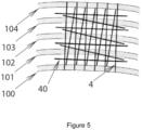
- Figure 5 exemplifies the use of an interwoven with threads on a group of ribs 100, 101, 102, 103, 104, according to the state of the art.
- the interwoven consists of a thread 4 that joins the different ribs and has threads 40 alternately placed above and below said thread 4 between ribs.
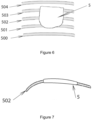
- Figure 6 exemplifies the use of a mesh-methacrylate sandwich 5 on a group of ribs 500, 501, 502, 503, 504, according to the state of the art.
- Figure 7 shows the application of the sandwich of Figure 6 , seen from the top side. A rib 502 and sandwich 5 are seen.
- Figure 8 shows a prosthesis 6 according to the invention.
- the prosthesis comprises a piece 60 longitudinally curved and several grooves 61 in its convex face.
- Figure 9 shows another view of the prosthesis 6. This view shows more clearly the curvature and warping on the longitudinal axis of the piece 60, which emulates the shape of the rib.
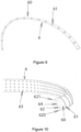
- Figure 10 is a view of a section of the prosthesis from its concave face and in the area of the end that will be located closer to the sternum. The warping of the piece 60 on its longitudinal axis is appreciated.
- the face 62 has the two transverse ends to the curved part 620, 621.
- the piece has projections 63 to improve bone fixation.
- the number of projections may vary depending on the part or possibly the part may not contain projections.
- the inlet opening 64 to the longitudinal channel intended to contain the opaque radio material.
- the other hole in the channel On the other end (not visible in this figure) is the other hole in the channel.
- the piece has a single channel, but the expert will understand that there could be more than one channel to place radiopaque material. The expert will also understand that the piece may not contain a channel for radiopaque material: this arrangement makes it more difficult to locate the prosthesis from outside the body, but does not prevent the normal functioning of the prosthesis.
- Figure 11 is a view of a section of the prosthesis from its concave face and in the area of the opposite end to that of Figure 10 , that is, the end that will be located closer to the spine. In this case it can be seen that the warping of the piece 60 on the longitudinal axis is different from that seen in Figure 10 .
- the face 65 has the two transverse ends to the curved piece 650, 651.
- Figure 12 is a complete view of a prosthesis from its concave face.
- the two ends 62, 65 and the holes 64, 66 of the entrance to the inner channel are appreciated to locate the radiopaque material.
- the projections 63 cover partially the concave face.
- Figure 13 is a complete view of the prosthesis from its convex face.
- Channel 7 carrying the radiopaque material is shown.
- the channel 7 is represented with a dotted line to represent that it is internal to the piece 60 and therefore is not visible from the outside (unless the prosthesis does manufacture in some transparent material).
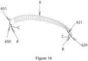
- Figure 14 makes it possible to better appreciate the warping of the piece 60. If the piece 6 is supported on a plane along its entire length, different angles can be seen at the ends.
- the C lines represent the plane on which the prosthesis rests.
- the angle formed between the plane and the line that joins the two ends 650, 651, belonging to the face 65 and which are transverse to the piece 60 is an angle A of 90 °.
- the angle between the plane and the line that joins the two transverse ends varies continuously as you move along the piece 60, until at the other end the angle formed between the plane and the line that joins the two ends 620, 621, belonging to the face 62 and which are transverse to the piece 60, is an acute angle B.
- Figure 15 is a detail of the face 65, in which the orifice 66 of entrance to the channel 7 can be seen.
- the angle between the line passing through the transverse ends 650, 651 and the support plane is 90 °.
- Figure 16 is a section of the piece 60 after advancing a few centimeters in a longitudinal direction from the face 65.
- the channel 7 is appreciated and that the angle between the line passing through the transverse ends and the support plane is a smaller angle of 90 °.
- Figure 17 is a view that allows a prosthesis according to the invention to be clearly seen from the convex face.
- Figure 18 is another view of the prosthesis of the invention, which allows to see the arch shape of the prosthesis.
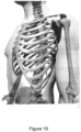
- Figure 19 shows a prosthesis, not forming part of the invention, fulfilling the function of splinting a fractured rib.
- the prosthesis is fixed in this case to the rib by means of suture thread (not shown) that passes through the grooves.
- Figure 20 shows the prosthesis of the invention fulfilling the function of partially replacing a fractured rib.
- the prosthesis is attached to the ends that remain in the rib and the structure's own rigidity, which is similar to that of the natural rib, allows the structure to behave naturally as if it were part of the rib during the inspiration and expiration movements.
- the prosthesis can be manufactured by any known method. For example, it could be manufactured by extrusion with subsequent shaping of the grooves. It could also be manufactured by injection, if it does not carry the channel for the opaque radio material.
- a preferred form of manufacturing would be by additive manufacturing (3D printing). Especially preferred is manufacturing by means of molten filament (FFI) or by laser sintering.
- FFI molten filament
- the prosthesis is sterilized by any known sterilization method and packaged in sterile form.
- sterilization methods autoclave sterilization, peroxide sterilization and ethylene oxide sterilization are cited. Especially preferred is ethylene oxide sterilization.
- the prosthesis that best suits the fractured rib is chosen and that will be the one that will rest properly against the bone. Then the prosthesis is adjusted with a suitable means, for example surgical thread, which passes through the grooves and is tied to the bone.
- a suitable means for example surgical thread
Landscapes
- Health & Medical Sciences (AREA)
- Orthopedic Medicine & Surgery (AREA)
- Life Sciences & Earth Sciences (AREA)
- Surgery (AREA)
- Animal Behavior & Ethology (AREA)
- Veterinary Medicine (AREA)
- Public Health (AREA)
- Engineering & Computer Science (AREA)
- Biomedical Technology (AREA)
- Heart & Thoracic Surgery (AREA)
- General Health & Medical Sciences (AREA)
- Molecular Biology (AREA)
- Medical Informatics (AREA)
- Nuclear Medicine, Radiotherapy & Molecular Imaging (AREA)
- Neurology (AREA)
- Cardiology (AREA)
- Oral & Maxillofacial Surgery (AREA)
- Transplantation (AREA)
- Vascular Medicine (AREA)
- Prostheses (AREA)
- Orthopedics, Nursing, And Contraception (AREA)
- Surgical Instruments (AREA)
Description
- The present invention is located in the field of therapeutic devices, specifically in the field of devices for replacing all or part of a rib.
- For the respiratory function to be fulfilled efficiently, the existence of a rib cage with ribs of normal shape and elasticity is essential. The fracture of one or more neighboring ribs can cause the mechanical stability of the costal wall to be lost in such a way that, at the time of inspiration, the area in which the fractures are located instead of expanding is sunk by the action of the negative pressure created in the ribcage while, at the time of expiration, instead of retracting it expands due to an increase in pressure.
- This disorder can endanger the life of the patient when the extent of the unstable sector - also called volet - is wide or its mobility, due to lack of rigidity, becomes important.
- The situation is similar in the case of surgical operations in which it is necessary to remove an area from the rib cage.
- One possibility to improve respiratory efficiency is to use respiratory mechanical assistance, also called internal pneumatic stabilization, by means of an artificial respirator. However, those patients who, due to the length and severity of their fractures must be connected for a prolonged period to a respirator, usually end up with thoracic deformations by welding the ribs in vicious positions. When the fractures are numerous, such deformations can become very pronounced and definitely compromise the patient's work and social life.
- Another possibility to improve respiratory efficiency is the use of surgical stabilization, through devices that can solve the problem. In that sense, various solutions have been presented to correct the problems generated by the loss of mechanical stability of the thorax.
- One technique to correct the problem has been the use of intramedullary nails. This device consists of a piece of thick stainless steel wire that is introduced through the convex face of the rib a few centimeters from the fracture focus and into the medullary canal of the bone. The fractured ends are faced and the wire is advanced through the medullary canal of the other fragment, causing it to exit through its convex face.
- Another technique consists in the use of metallic agrafes. Metal agrafes are thin pieces formed by a narrow sheet that supports a series of open clamps. After facing each of the fractured ends, the clamps are closed and tightened with a special clamp on the healthy bone, thereby fixing the focus of the fracture.
- The intramedullary nail technique and the agrafes technique present the problem that both the nails and the agrafes are straight, which causes the rib to lose its normal curvature and elasticity, which affects its function and aesthetic aspects.
- Additionally, in elderly patients and especially when they suffer fractures of the anterior third of the rib, these devices cannot be placed because the bone at that level has very little wall and the wall is spongy. Under such conditions, the wires are loose and the agrafes are embedded in the bone (such inconveniences become relevant because the most serious volets are the previous ones and because it is the elderly patients who least tolerate broad rib fractures).
- Another technique involves the use of metal splints. Metal splints are simple metal strips that are molded to the shape of the rib, fixed to it by means of ligatures and after a while they must be removed by a new surgical intervention.
- The technique based on metal splints has the drawback that it is not possible to obtain a perfect curvature in manual molding and must be removed after a certain time by further intervention. Likewise, treated patients cannot undergo certain diagnostic techniques, such as magnetic resonance imaging, thus being deprived of access to an important diagnostic resource.
- In cases of large rib resections, different procedures have been used to replace the excised wall:
- Interewoven with threads of different constitution, created in situ during the operative act with or without the addition of prefabricated meshes.
- Mesh and methacrylate sandwiches, the result of the creation of a prosthesis manufactured based on a piece of methyl methacrylate mesh in microspheres mixed with catalyst, which is then covered with a new mesh layer. Once the resulting layer is solidified, a kind of rigid plastron or shell with fabric edges is obtained in which the fixing points are located.
- Some surgeons mold synthetic thread, a paste formed by the sandwich is spread over the patient's flank and with this a curved prosthesis is obtained, but of a curvature different from that of the excised wall sector.
- Other operators, in order to avoid the damage caused to the patient by the intense heat developed by the exothermic reaction of methacrylate polymerization, manufacture the plastron on a sterile table and in such cases the resulting plastron is flat.
- These procedures have proven effective for occlusion of the gap, but both also have drawbacks. The interweaves provide a repair that is often sufficient to save the patient's life, but the intervened wall is left with some permanent instability.
- The sandwiches, on the other hand, result in a good repair, but the wall is rigid and with a bulky foreign body that the patient will definitely carry, consisting of a heavy mass of methacrylate in different degrees of polymerization. According to the experience resulting from its use in hip prosthesis surgery, situations of intolerance of the tissues to the methacrylate thus manipulated can also occur.
- An improvement to the prior techniques was presented in the UY32513 Invention Patent application. Said application teaches a costal prosthesis of methyl methacrylate polymerized by physical means having the shape of a thin curved sheet and the profile of an angled "C". The device, however, requires the use of a lot of material, is relatively bulky and has a wide profile, which makes it feel comfortable. Additionally, if it is necessary to cut the prosthesis to adjust its length, the use of sterile tools will be necessary. The presence of holes makes it necessary to pierce the rib in order to insert the prosthesis. Cutting the prosthesis with tools generates dust in the operating room.
- The placement of the rib on the bone requires perforations, suturing and eventually cutting with sterile tools, which requires considerable operating time, more expenses and greater risk.
- Application
ES2574759 - However, the
ES2574759 ES2574759 - Another form of fractured rib joint is that provided by DePuy Synthes with the MatrixRIB system (https://www.depuysynthes.com/hcp/cmf/products/qs/MATRIX_RIB_Fixation_System?utm_source=Matri xRibContent&utm_medium=Providers). Said system consists of a series of pre-contoured plates, closing screws and splints that allow the fractured rib to be held together, similar to the teachings of
ES2574759 ES2574759 - Document
US 2006/085000 A1 discloses bone plates for fixing fractured ribs. - Document
DE 38 03 435 C1 describes an implant splint for rib fractures made of resorbable material that has grooves to pass threads, also made of resorbable material, to fasten the splint to a fractured rib. - The object of the present application is a prosthesis for replacing all or part of the ribs that may have been removed as a result of thoracic wall surgery. Thus, the prosthesis of the invention can also be used in the reconstruction of the chest wall.
- The prosthesis of the invention allows replacing all or part of the rib, reduces operating times, is easily fractional without leaving loose material and does not require any special fastening element.
- The prosthesis of the invention has a flexibility similar to that of the natural ribs and does not need removal, that is to say that a new surgical intervention is not necessary to remove the prosthesis.
- A summary description of the figures is given below.
-
Figure 1 shows the components of a fractured rib. -
Figure 2 shows the use of an intramedullary nail in a fractured rib, according to the prior art. -
Figure 3 shows a metallic agrafe to be used on a fractured rib, according to the prior art. -
Figure 4 shows the application of a similar agrafe to that ofFigure 3 on a fractured rib, according to the prior art. -
Figure 5 exemplifies the use of an interwoven with threads on a group of fractured ribs, according to the prior art. -
Figure 6 exemplifies the use of a mesh-methacrylate sandwich on a group of fractured ribs, according to the prior art. -
Figure 7 shows the application of the sandwich ofFigure 6 , seen from the top side, according to the prior art. -
Figure 8 shows a complete prosthesis according to the invention. -
Figure 9 shows another complete view of the prosthesis of the invention. -
Figure 10 is a view of a section of the prosthesis of the invention from its concave face in which one end of the prosthesis can be seen. -
Figure 11 is a view of a section of the prosthesis of the invention from its concave face in which the other end of the prosthesis can be seen. -
Figure 12 is a complete view of a prosthesis of the invention from its concave face -
Figure 13 is a complete view of a prosthesis of the invention from its convex face, in which the channel for the radiopaque substance is shown. -
Figure 14 is a figure that allows to appreciate the warping of the prosthesis of the invention. -
Figure 15 is a detail of the face of one of the ends of the prosthesis of the invention. -
Figure 16 is a cross section of the prosthesis of the invention. -
Figure 17 is a view that allows the prosthesis of the invention to be seen from the convex face. -
Figure 18 is another view of the prosthesis of the invention. -
Figure 19 shows a prosthesis of the invention that is stabilizing a fractured rib. This embodiment does not belong to the invention. -
Figure 20 shows a prosthesis of the invention that is partially replacing a rib. - The object of the invention is an individual prosthesis for replacing all or part of a rib, characterized by comprising:
- a- a piece curved in the longitudinal direction in the form of an arc, said piece also presenting a curvature in the transverse direction that defines a concave face, the concave face being the face that rests on the rib, and a convex face, the convex face being the face opposite to the concave face, and a warping along the longitudinal axis and
- b- two or more transverse grooves located on the convex face that allow the prosthesis fixing elements to be accommodated to the rib, without the need to pierce the rib, and allow the prosthesis to be cut manually
- The "concave face" is the face of the curved piece that rests on the rib, once the prosthesis is used.
- The "convex face" is the face of the curved piece that faces the outer side of the body, once the prosthesis is used, that is, the face opposite to the "concave face".
- By "splinting", not forming part of the invention, it should be understood that the prosthesis allows two parts of a fractured rib to be helo firmly so that the fractured ends are facing and located next to each other to allow the bone to weld. Splinting prevents fractured ends from moving and thus allows proper bone welding.
- Preferably, the prosthesis will be constructed in a material that has a stiffness (and therefore also an elasticity) comparable to the natural stiffness (and elasticity) of the ribs, so as to facilitate the necessary bending for a correct support on the outer surface of the rib. "Correct support" means a firm and uniform support against the bone. Thus, the prosthesis behaves similarly to a natural rib during inspiration and expiration movements.
- The outer surface of the human rib has curvature on its longitudinal axis and that curvature changes as it goes from the spine to the sternum area. Therefore, the expert will understand that the curved piece must have a warping on its own longitudinal axis, so as to emulate the outer surface of a human rib. This configuration will facilitate the correct support on the outer surface of the rib.
- Warping along the longitudinal axis implies that, if the prosthesis rests on a plane over its length, the angle formed between the plane and the line that joins the two transverse ends to the curved piece on the face of one of the ends Longitudinal will be approximately 90 °, so as to emulate the shape of the rib in the area of the spine, while the angle formed between the plane and the line that joins the two transverse ends to the curved piece will gradually decrease along the piece and on the face of the other of the longitudinal ends the angle formed between the plane and the line that joins the two transverse ends will be an acute angle, so as to emulate the shape of the rib in the sternum area. Obviously, the acute angle and therefore warping will depend on the rib for which the prosthesis is applied.
- The said angle of approximately 90 ° will preferably be between 85 ° and 95 °. Preferably, it will be an angle of 90 °.
- The aforementioned acute angle depends on the rib for which the prosthesis is intended to be applied.
- The warping along the axis is then performed so that the prosthesis takes an approximate shape to that of the fractured rib, so that the prosthesis that best fits the shape of a particular rib can be chosen and can be supported correctly over the fractured rib. In other words, warping along the axis approximately emulates the shape of a certain rib or a group of ribs.
- The transverse grooves fulfill two functions: they allow the prosthesis fixing elements to be accommodated to the rib and allow the prosthesis to be cut manually, without tools, to adjust it to the desired length.
- The presence of grooves allows the prosthesis to be attached to the rib by means of fixing elements and in this way there is no need to pierce the rib. This procedure reduces operating time, which is of fundamental importance in an operation because surgery times are reduced, operating room costs are reduced and less anesthesia is required (because the operating time is reduced). Any known biocompatible fixation means can be used to fix the prosthesis to the rib, and no special fixation means are necessary. For example, suture thread or conventional sterile seals can be used.
- In some cases it may be necessary to cut the prosthesis to adjust its length to the desired length. To cut the prosthesis, it will be enough for the surgeon to press with his thumbs on both sides of the chosen groove. The groove will behave like a weak zone that will allow the piece to be cut. This is also relevant in a surgical intervention, because the operating time of the operating room is reduced, sterile tools are not required and no dust is generated.
- Preferably, the transverse grooves will be uniformly spaced along the curved piece.
- The prosthesis does not require the existence of through holes, which helps to facilitate its fabrication.
- Ribs are not all the same: each rib has its own length and curvature. The expert will then understand that the prosthesis should fit the fractured rib, so there will not be a single size of prosthesis. It will usually be convenient to have four or five prostheses for the ribs on the right side and four or five prostheses for the ribs on the left side, especially for emergency situations.
- Since the prosthesis has a certain degree of flexibility and elasticity, it is possible to bend it slightly to adapt it to the shape of the rib. For that reason, it is enough with four or five rib prostheses of each side so that it is possible to use any of the prostheses with a particular rib. The expert will not have difficulty choosing the right prosthesis for each case.
- Obviously, if necessary, it is possible to manufacture a customized prosthesis for a particular rib, since the manufacturing process is relatively quick. In that case, the warping along the axis will follow exactly the natural warping of the rib, so as to replicate its shape.
- Preferably, the prostheses will have an average size of 290mm long, 10mm wide and 3mm thick, with a variation of +/- 30% in any of these dimensions, according to which ribs the prosthesis is directed.
- Preferred materials for the construction of the prosthesis are biocompatible polymeric materials. Especially preferred is polyether ether ketone (PEEK). The polyether ether ketone makes it possible to manufacture a prosthesis that has a degree of stiffness comparable to the natural flexibility of the ribs.
- Preferably, at least one line of radiopaque material will be included within the body of the prosthesis and throughout its length. This will facilitate your radiological visibility.
- Preferably, that line of radiopaque material will be formed by a substance that contains radiopaque material, said substance being incorporated in a channel that travels the curved piece from one end to the other. In those cases in which it is desired to include a radiopaque material, the curved piece will have at each of its longitudinal ends, a hole that connects with the channel that the piece will travel along its entire length. Through one of these holes the radiopaque material will be injected along the entire channel. Preferably, the radiopaque material is included in a resin that flows through the channel and then polymerizes and solidifies. The expert will understand that the curved piece can be constructed with more than one longitudinal channel, so as to have more than one line of radiopaque material.
- Examples of radiopaque materials that can be used are barium sulfate and iodinated contrast media, such as iotalamate, ioxaglate or iopamidol.
- Preferably, the surface of the concave face will not be flat, but will have relief to facilitate support. Especially preferred is the presence of projections or projections, which not only facilitate support, but allow the tissue to grow around said reliefs and thereby help to keep the prosthesis fixed. The projections may be distributed over the entire surface of the concave face or only part thereof, although it is preferred that the projections be distributed over the entire surface, more preferably that said distribution is uniform.
- By "projections or protrusions" it refers to elements that protrude from the surface of the convex face.
- Preferably, the projections will have a pyramidal shape. However, the expert will understand that he can give it any other suitable form, such as, for example, conical, cylindrical or striated.
- Below are drawings that allow a better understanding of the invention. The drawings should be considered as particular embodiments of the invention, not being in any way limiting thereof.
-
Figure 1 shows a fracturedrib 1, with fractured ends 11, 12. Therib 1 is then divided into twosegments concave face 14 of the rib is shown
Figure 2 shows the use of an intramedullary nail to repair the fracture, according to the state of the art. In this technique, the nail, which consists of athick wire 2, is introduced through theconvex face 13 of one of thesegments 1b of the fracturedrib 1 a few centimeters from thefracture focus 10 and into the medullary canal of the bone. The fractured ends are faced and thewire 2 is advanced through the medullary canal of the bone until it exits theconvex face 13 of theother segment 1a of the fracturedrib 2
Fig. 3 shows ametallic agrafe 3 according to the state of the art. The agrafe comprises anarrow sheet 30 that supports a series ofopen clamps 31. In this case four clamps are shown, but the number could be greater or lesser. -
Figure 4 shows the application of theagrafe 3 in a fracturedrib 1. The fractured ends are faced, theagrafe 3 is placed and then theclamps 31 are closed and tightened on the healthy bone with a special clamp, thereby fixing the focus offracture 10. -
Figure 5 exemplifies the use of an interwoven with threads on a group ofribs thread 4 that joins the different ribs and hasthreads 40 alternately placed above and below saidthread 4 between ribs. -
Figure 6 exemplifies the use of a mesh-methacrylate sandwich 5 on a group ofribs -
Figure 7 shows the application of the sandwich ofFigure 6 , seen from the top side. Arib 502 andsandwich 5 are seen. -
Figure 8 shows aprosthesis 6 according to the invention. The prosthesis comprises apiece 60 longitudinally curved andseveral grooves 61 in its convex face. -
Figure 9 shows another view of theprosthesis 6. This view shows more clearly the curvature and warping on the longitudinal axis of thepiece 60, which emulates the shape of the rib. -
Figure 10 is a view of a section of the prosthesis from its concave face and in the area of the end that will be located closer to the sternum. The warping of thepiece 60 on its longitudinal axis is appreciated. Theface 62 has the two transverse ends to thecurved part - In this case, the piece has
projections 63 to improve bone fixation. The number of projections may vary depending on the part or possibly the part may not contain projections. - Also shown on
face 62 is the inlet opening 64 to the longitudinal channel intended to contain the opaque radio material. On the other end (not visible in this figure) is the other hole in the channel. In this case, the piece has a single channel, but the expert will understand that there could be more than one channel to place radiopaque material. The expert will also understand that the piece may not contain a channel for radiopaque material: this arrangement makes it more difficult to locate the prosthesis from outside the body, but does not prevent the normal functioning of the prosthesis. -
Figure 11 is a view of a section of the prosthesis from its concave face and in the area of the opposite end to that ofFigure 10 , that is, the end that will be located closer to the spine. In this case it can be seen that the warping of thepiece 60 on the longitudinal axis is different from that seen inFigure 10 . Theface 65 of the other longitudinal end of the prosthesis and theother entrance hole 66 to the channel for the radiopaque material. Theface 65 has the two transverse ends to thecurved piece -
Figure 12 is a complete view of a prosthesis from its concave face. The two ends 62, 65 and theholes projections 63 cover partially the concave face. -
Figure 13 is a complete view of the prosthesis from its convex face.Channel 7 carrying the radiopaque material is shown. Thechannel 7 is represented with a dotted line to represent that it is internal to thepiece 60 and therefore is not visible from the outside (unless the prosthesis does manufacture in some transparent material). -
Figure 14 makes it possible to better appreciate the warping of thepiece 60. If thepiece 6 is supported on a plane along its entire length, different angles can be seen at the ends. The C lines represent the plane on which the prosthesis rests. - At one end, the angle formed between the plane and the line that joins the two ends 650, 651, belonging to the
face 65 and which are transverse to thepiece 60, is an angle A of 90 °. The angle between the plane and the line that joins the two transverse ends varies continuously as you move along thepiece 60, until at the other end the angle formed between the plane and the line that joins the two ends 620, 621, belonging to theface 62 and which are transverse to thepiece 60, is an acute angle B. - This form is convenient because in that way the
prosthesis 6 emulates the shape of the rib. The curvature and warping of thepiece 60 allows a better support against the convex surface of the rib. -
Figure 15 is a detail of theface 65, in which theorifice 66 of entrance to thechannel 7 can be seen. The angle between the line passing through the transverse ends 650, 651 and the support plane is 90 °. -
Figure 16 is a section of thepiece 60 after advancing a few centimeters in a longitudinal direction from theface 65. Thechannel 7 is appreciated and that the angle between the line passing through the transverse ends and the support plane is a smaller angle of 90 °. -
Figure 17 is a view that allows a prosthesis according to the invention to be clearly seen from the convex face. -
Figure 18 is another view of the prosthesis of the invention, which allows to see the arch shape of the prosthesis. -
Figure 19 shows a prosthesis, not forming part of the invention, fulfilling the function of splinting a fractured rib. The prosthesis is fixed in this case to the rib by means of suture thread (not shown) that passes through the grooves. -
Figure 20 shows the prosthesis of the invention fulfilling the function of partially replacing a fractured rib. - For this, the prosthesis is attached to the ends that remain in the rib and the structure's own rigidity, which is similar to that of the natural rib, allows the structure to behave naturally as if it were part of the rib during the inspiration and expiration movements.
- The prosthesis can be manufactured by any known method. For example, it could be manufactured by extrusion with subsequent shaping of the grooves. It could also be manufactured by injection, if it does not carry the channel for the opaque radio material.
- A preferred form of manufacturing would be by additive manufacturing (3D printing). Especially preferred is manufacturing by means of molten filament (FFI) or by laser sintering.
- Once the prosthesis is manufactured, it is sterilized by any known sterilization method and packaged in sterile form.
- As preferred sterilization methods, autoclave sterilization, peroxide sterilization and ethylene oxide sterilization are cited. Especially preferred is ethylene oxide sterilization.
- To apply the prosthesis, the prosthesis that best suits the fractured rib is chosen and that will be the one that will rest properly against the bone. Then the prosthesis is adjusted with a suitable means, for example surgical thread, which passes through the grooves and is tied to the bone.
- Methods of manufacture, sterilisation and application of the prosthesis do not form part of the invention.
Claims (10)
- An individual prosthesis (6) for replacing all or part of a rib, said prosthesis characterized by comprising:a- a piece curved in the longitudinal direction in the form of an arc (60), said piece also presenting a curvature in the transverse direction that defines a concave face, the concave face being the face that rests on the rib, and a convex face , the convex face being the face opposite to the concave face, and a warping along the longitudinal axis andb- two or more transverse grooves (61) located on the convex face that allow the prosthesis fixing elements to be accommodated to the rib, without the need to pierce the rib, and allow the prosthesis to be cut manually
- The prosthesis according to claim 1, characterized in that the concave face has projections (63).
- The prosthesis according to claim 1, characterized in that the transverse grooves (61) are also spaced apart.
- The prosthesis according to claim 2, characterized in that the transverse grooves (61) are also spaced apart.
- The prosthesis according to claim 1, characterized in that it has at least one line of radiopaque material (7).
- The prosthesis according to claim 2, characterized in that it has at least one line of radiopaque material (7).
- The prosthesis according to claim 3, characterized in that it has at least one line of radiopaque material.
- The prosthesis according to claim 4, characterized in that it has at least one line of radiopaque material (7).
- The prosthesis according to any of the preceding claims, characterized in that the material of said prosthesis is polyether ether ketone.
- The prosthesis according to claim 9, characterized in that it is manufactured by 3D printing.
Applications Claiming Priority (2)
| Application Number | Priority Date | Filing Date | Title |
|---|---|---|---|
| UY0001038363A UY38363A (en) | 2019-09-09 | 2019-09-09 | ELASTIC RIB PROSTHESES |
| PCT/EP2019/081442 WO2021047787A1 (en) | 2019-09-09 | 2019-11-15 | Elastic prosthetics of ribs |
Publications (2)
| Publication Number | Publication Date |
|---|---|
| EP4003199A1 EP4003199A1 (en) | 2022-06-01 |
| EP4003199B1 true EP4003199B1 (en) | 2025-04-02 |
Family
ID=68610221
Family Applications (1)
| Application Number | Title | Priority Date | Filing Date |
|---|---|---|---|
| EP19805629.3A Active EP4003199B1 (en) | 2019-09-09 | 2019-11-15 | Elastic prosthetics of ribs |
Country Status (16)
| Country | Link |
|---|---|
| US (1) | US20220323127A1 (en) |
| EP (1) | EP4003199B1 (en) |
| JP (1) | JP2022546858A (en) |
| AR (1) | AR117536A1 (en) |
| BR (1) | BR112022004360A2 (en) |
| CA (1) | CA3149983A1 (en) |
| CO (1) | CO2022002639A2 (en) |
| CR (1) | CR20220088A (en) |
| EC (1) | ECSP22017383A (en) |
| IL (1) | IL291135A (en) |
| MX (1) | MX2022002874A (en) |
| PE (1) | PE20220929A1 (en) |
| PY (1) | PY19101995A (en) |
| UY (1) | UY38363A (en) |
| WO (1) | WO2021047787A1 (en) |
| ZA (1) | ZA202202877B (en) |
Family Cites Families (16)
| Publication number | Priority date | Publication date | Assignee | Title |
|---|---|---|---|---|
| DE7903184U1 (en) * | 1979-02-06 | 1979-05-03 | Howmedica International, Inc. Zweigniederlassung Kiel, 2301 Schoenkirchen | Implant for fixation of broken ribs |
| DE3803435C1 (en) * | 1988-02-05 | 1989-09-21 | Ethicon Gmbh & Co Kg, 2000 Norderstedt, De | Implanted splint for rib fractures |
| JPH02211141A (en) * | 1989-02-10 | 1990-08-22 | Dan Sangyo Kk | Inner splint for fixing broken bone part |
| ITRM20010123A1 (en) * | 2001-03-09 | 2002-09-09 | Leonardo Bordi | INTERNAL BAND FIXER FOR FRACTURE AND BONE PROSTHESIS. |
| US7785355B2 (en) * | 2004-10-20 | 2010-08-31 | Synthes Usa, Llc | System for rib fixation |
| US8709055B2 (en) * | 2009-01-16 | 2014-04-29 | Carbofix Orthopedics Ltd. | Composite material bone implant |
| CN201612683U (en) * | 2010-02-04 | 2010-10-27 | 中国人民解放军第四军医大学 | Non-encircling rib fixation plate |
| EP2667809B1 (en) * | 2011-01-25 | 2015-11-04 | Synthes GmbH | Expandable bone fixation implant |
| US9517096B2 (en) * | 2012-01-10 | 2016-12-13 | The Charlotte-Mecklenburg Hospital Authority | Method and system for longitudinal closure of dissected sternums |
| US10231767B2 (en) * | 2013-03-15 | 2019-03-19 | The Penn State Research Foundation | Bone repair system, kit and method |
| US10070904B2 (en) * | 2014-02-21 | 2018-09-11 | Jeko Metodiev Madjarov | Bone fixation implants |
| US10265174B2 (en) * | 2014-07-24 | 2019-04-23 | Xilloc Medical B.V. | Implant with suture anchors and method |
| ES2574759B1 (en) | 2014-11-21 | 2017-04-06 | Jmborro S.L. | DEVICE FOR THE TREATMENT OF COSTAL FRACTURES |
| CA2976333C (en) * | 2015-02-13 | 2021-11-09 | Biomet Manufacturing, Llc | Rib reconstruction device |
| US10368928B2 (en) * | 2017-03-13 | 2019-08-06 | Globus Medical, Inc. | Bone stabilization systems |
| JP6573263B2 (en) * | 2018-10-11 | 2019-09-11 | ヤマウチマテックス・エンジニアリング株式会社 | Artificial bone shaft |
-
2019
- 2019-09-09 UY UY0001038363A patent/UY38363A/en active IP Right Grant
- 2019-11-15 EP EP19805629.3A patent/EP4003199B1/en active Active
- 2019-11-15 WO PCT/EP2019/081442 patent/WO2021047787A1/en not_active Ceased
- 2019-11-15 MX MX2022002874A patent/MX2022002874A/en unknown
- 2019-11-15 CA CA3149983A patent/CA3149983A1/en active Pending
- 2019-11-15 JP JP2022515635A patent/JP2022546858A/en active Pending
- 2019-11-15 CR CR20220088A patent/CR20220088A/en unknown
- 2019-11-15 BR BR112022004360A patent/BR112022004360A2/en active Search and Examination
- 2019-11-15 US US17/641,035 patent/US20220323127A1/en not_active Abandoned
- 2019-11-15 PE PE2022000331A patent/PE20220929A1/en unknown
- 2019-12-04 PY PY201919101995A patent/PY19101995A/en unknown
- 2019-12-26 AR ARP190103891A patent/AR117536A1/en active IP Right Grant
-
2022
- 2022-03-04 CO CONC2022/0002639A patent/CO2022002639A2/en unknown
- 2022-03-06 IL IL291135A patent/IL291135A/en unknown
- 2022-03-08 EC ECSENADI202217383A patent/ECSP22017383A/en unknown
- 2022-03-09 ZA ZA2022/02877A patent/ZA202202877B/en unknown
Also Published As
| Publication number | Publication date |
|---|---|
| JP2022546858A (en) | 2022-11-09 |
| PE20220929A1 (en) | 2022-05-31 |
| EP4003199A1 (en) | 2022-06-01 |
| ECSP22017383A (en) | 2022-05-31 |
| AR117536A1 (en) | 2021-08-11 |
| US20220323127A1 (en) | 2022-10-13 |
| UY38363A (en) | 2021-02-26 |
| CR20220088A (en) | 2022-07-01 |
| CO2022002639A2 (en) | 2022-04-19 |
| BR112022004360A2 (en) | 2022-05-31 |
| PY19101995A (en) | 2021-07-02 |
| CA3149983A1 (en) | 2021-03-18 |
| WO2021047787A1 (en) | 2021-03-18 |
| IL291135A (en) | 2022-05-01 |
| MX2022002874A (en) | 2022-06-08 |
| ZA202202877B (en) | 2024-07-31 |
Similar Documents
| Publication | Publication Date | Title |
|---|---|---|
| Cohen et al. | Mandibular reconstruction using stereolithographic 3-dimensional printing modeling technology | |
| US3710789A (en) | Method of repairing bone fractures with expanded metal | |
| US20190307495A1 (en) | Surgical implant for correction of hallux valgus or tailor's bunion | |
| US7887587B2 (en) | Soft tissue spacer | |
| DE69207733T2 (en) | Restoration implant for eye sockets | |
| BRPI0616942A2 (en) | bone alignment implant system, methods for correcting a spinal deformity, for implanting a bone alignment implant on a spinal column and for correcting a spinal deformity | |
| RU2512785C2 (en) | Repair plate for posttraumatic defects and deformities of eye grounds | |
| US20150238237A1 (en) | Bone fixation implants | |
| JOHNSON et al. | Treatment of congenital hip dislocation and dysplasia with the Pavlik harness | |
| US20220323127A1 (en) | Elastic prosthetics of ribs | |
| JP2024530259A (en) | NON-PATIENT-SPECIFIC CRANIOFACIAL IMPLANTS FOR CORRECTING AND/OR PREVENTING TEMPORAL OR PTERION DEFORMITIES - Patent application | |
| RU2621949C1 (en) | Combined implant and instruments for its installation | |
| Shirakabe et al. | A new type of prosthesis for augmentation rhinoplasty: our experience in 1600 cases | |
| RU2645646C1 (en) | Compression mask for postoperative cooling patient's soft facial tissue | |
| Orzell et al. | Secondary repair of the zygoma | |
| RU2301048C2 (en) | Femoral endoprosthesis | |
| RU2201720C2 (en) | Open osteosynthesis method for treating the cases of radial bone fracture in children and teenagers | |
| RU2140222C1 (en) | Method of plasty of ring-shaped ligament of radius head | |
| RU2809793C2 (en) | Method of manufacturing individual premodeled elastically stressed structure-fixator and method of treating intra-articular fractures of proximal and distal epimetaphyses of tibia using individual premodeled elastically stressed structure-fixator | |
| RU6696U1 (en) | LOCK FOR COMPRESSION OSTEOSYNTHESIS | |
| RU2342914C1 (en) | Method of treament of deformation limbs' bones of patients with metabolic osteopathy and osteogenesis imperfecta | |
| RU190629U1 (en) | BELT CLAMPS | |
| Rotaru et al. | Reconstruction of the calvarial defects using custom-made cranioplasty plates | |
| Leake et al. | Neurocranial reconstruction using an elastomer‐coated cloth mesh and bone grafting | |
| Reuters et al. | Experience And Results With Preoperatively Shaped AO Mandibular Reconstruction Plates |
Legal Events
| Date | Code | Title | Description |
|---|---|---|---|
| STAA | Information on the status of an ep patent application or granted ep patent |
Free format text: STATUS: UNKNOWN |
|
| STAA | Information on the status of an ep patent application or granted ep patent |
Free format text: STATUS: THE INTERNATIONAL PUBLICATION HAS BEEN MADE |
|
| PUAI | Public reference made under article 153(3) epc to a published international application that has entered the european phase |
Free format text: ORIGINAL CODE: 0009012 |
|
| STAA | Information on the status of an ep patent application or granted ep patent |
Free format text: STATUS: REQUEST FOR EXAMINATION WAS MADE |
|
| 17P | Request for examination filed |
Effective date: 20220225 |
|
| AK | Designated contracting states |
Kind code of ref document: A1 Designated state(s): AL AT BE BG CH CY CZ DE DK EE ES FI FR GB GR HR HU IE IS IT LI LT LU LV MC MK MT NL NO PL PT RO RS SE SI SK SM TR |
|
| DAV | Request for validation of the european patent (deleted) | ||
| DAX | Request for extension of the european patent (deleted) | ||
| STAA | Information on the status of an ep patent application or granted ep patent |
Free format text: STATUS: EXAMINATION IS IN PROGRESS |
|
| 17Q | First examination report despatched |
Effective date: 20240418 |
|
| GRAP | Despatch of communication of intention to grant a patent |
Free format text: ORIGINAL CODE: EPIDOSNIGR1 |
|
| STAA | Information on the status of an ep patent application or granted ep patent |
Free format text: STATUS: GRANT OF PATENT IS INTENDED |
|
| INTG | Intention to grant announced |
Effective date: 20241106 |
|
| GRAS | Grant fee paid |
Free format text: ORIGINAL CODE: EPIDOSNIGR3 |
|
| GRAA | (expected) grant |
Free format text: ORIGINAL CODE: 0009210 |
|
| STAA | Information on the status of an ep patent application or granted ep patent |
Free format text: STATUS: THE PATENT HAS BEEN GRANTED |
|
| AK | Designated contracting states |
Kind code of ref document: B1 Designated state(s): AL AT BE BG CH CY CZ DE DK EE ES FI FR GB GR HR HU IE IS IT LI LT LU LV MC MK MT NL NO PL PT RO RS SE SI SK SM TR |
|
| RAP3 | Party data changed (applicant data changed or rights of an application transferred) |
Owner name: EMEDICAL SOCIEDAD ANONIMA Owner name: OROMI, GASTON ENRIQUE |
|
| REG | Reference to a national code |
Ref country code: GB Ref legal event code: FG4D |
|
| REG | Reference to a national code |
Ref country code: CH Ref legal event code: EP |
|
| REG | Reference to a national code |
Ref country code: IE Ref legal event code: FG4D |
|
| REG | Reference to a national code |
Ref country code: DE Ref legal event code: R096 Ref document number: 602019068160 Country of ref document: DE |
|
| REG | Reference to a national code |
Ref country code: NL Ref legal event code: MP Effective date: 20250402 |
|
| PG25 | Lapsed in a contracting state [announced via postgrant information from national office to epo] |
Ref country code: NL Free format text: LAPSE BECAUSE OF FAILURE TO SUBMIT A TRANSLATION OF THE DESCRIPTION OR TO PAY THE FEE WITHIN THE PRESCRIBED TIME-LIMIT Effective date: 20250402 |
|
| REG | Reference to a national code |
Ref country code: AT Ref legal event code: MK05 Ref document number: 1780528 Country of ref document: AT Kind code of ref document: T Effective date: 20250402 |
|
| PG25 | Lapsed in a contracting state [announced via postgrant information from national office to epo] |
Ref country code: ES Free format text: LAPSE BECAUSE OF FAILURE TO SUBMIT A TRANSLATION OF THE DESCRIPTION OR TO PAY THE FEE WITHIN THE PRESCRIBED TIME-LIMIT Effective date: 20250402 Ref country code: PT Free format text: LAPSE BECAUSE OF FAILURE TO SUBMIT A TRANSLATION OF THE DESCRIPTION OR TO PAY THE FEE WITHIN THE PRESCRIBED TIME-LIMIT Effective date: 20250804 Ref country code: FI Free format text: LAPSE BECAUSE OF FAILURE TO SUBMIT A TRANSLATION OF THE DESCRIPTION OR TO PAY THE FEE WITHIN THE PRESCRIBED TIME-LIMIT Effective date: 20250402 |
|
| REG | Reference to a national code |
Ref country code: LT Ref legal event code: MG9D |
|
| PG25 | Lapsed in a contracting state [announced via postgrant information from national office to epo] |
Ref country code: GR Free format text: LAPSE BECAUSE OF FAILURE TO SUBMIT A TRANSLATION OF THE DESCRIPTION OR TO PAY THE FEE WITHIN THE PRESCRIBED TIME-LIMIT Effective date: 20250703 Ref country code: NO Free format text: LAPSE BECAUSE OF FAILURE TO SUBMIT A TRANSLATION OF THE DESCRIPTION OR TO PAY THE FEE WITHIN THE PRESCRIBED TIME-LIMIT Effective date: 20250702 |
|
| PG25 | Lapsed in a contracting state [announced via postgrant information from national office to epo] |
Ref country code: PL Free format text: LAPSE BECAUSE OF FAILURE TO SUBMIT A TRANSLATION OF THE DESCRIPTION OR TO PAY THE FEE WITHIN THE PRESCRIBED TIME-LIMIT Effective date: 20250402 |
|
| PG25 | Lapsed in a contracting state [announced via postgrant information from national office to epo] |
Ref country code: BG Free format text: LAPSE BECAUSE OF FAILURE TO SUBMIT A TRANSLATION OF THE DESCRIPTION OR TO PAY THE FEE WITHIN THE PRESCRIBED TIME-LIMIT Effective date: 20250402 |
|
| PG25 | Lapsed in a contracting state [announced via postgrant information from national office to epo] |
Ref country code: HR Free format text: LAPSE BECAUSE OF FAILURE TO SUBMIT A TRANSLATION OF THE DESCRIPTION OR TO PAY THE FEE WITHIN THE PRESCRIBED TIME-LIMIT Effective date: 20250402 |
|
| PG25 | Lapsed in a contracting state [announced via postgrant information from national office to epo] |
Ref country code: AT Free format text: LAPSE BECAUSE OF FAILURE TO SUBMIT A TRANSLATION OF THE DESCRIPTION OR TO PAY THE FEE WITHIN THE PRESCRIBED TIME-LIMIT Effective date: 20250402 |
|
| PG25 | Lapsed in a contracting state [announced via postgrant information from national office to epo] |
Ref country code: RS Free format text: LAPSE BECAUSE OF FAILURE TO SUBMIT A TRANSLATION OF THE DESCRIPTION OR TO PAY THE FEE WITHIN THE PRESCRIBED TIME-LIMIT Effective date: 20250702 |
|
| PG25 | Lapsed in a contracting state [announced via postgrant information from national office to epo] |
Ref country code: IS Free format text: LAPSE BECAUSE OF FAILURE TO SUBMIT A TRANSLATION OF THE DESCRIPTION OR TO PAY THE FEE WITHIN THE PRESCRIBED TIME-LIMIT Effective date: 20250802 |
|
| PG25 | Lapsed in a contracting state [announced via postgrant information from national office to epo] |
Ref country code: LV Free format text: LAPSE BECAUSE OF FAILURE TO SUBMIT A TRANSLATION OF THE DESCRIPTION OR TO PAY THE FEE WITHIN THE PRESCRIBED TIME-LIMIT Effective date: 20250402 |
|
| REG | Reference to a national code |
Ref country code: DE Ref legal event code: R097 Ref document number: 602019068160 Country of ref document: DE |
|
| PG25 | Lapsed in a contracting state [announced via postgrant information from national office to epo] |
Ref country code: SM Free format text: LAPSE BECAUSE OF FAILURE TO SUBMIT A TRANSLATION OF THE DESCRIPTION OR TO PAY THE FEE WITHIN THE PRESCRIBED TIME-LIMIT Effective date: 20250402 Ref country code: DK Free format text: LAPSE BECAUSE OF FAILURE TO SUBMIT A TRANSLATION OF THE DESCRIPTION OR TO PAY THE FEE WITHIN THE PRESCRIBED TIME-LIMIT Effective date: 20250402 |
|
| PG25 | Lapsed in a contracting state [announced via postgrant information from national office to epo] |
Ref country code: CZ Free format text: LAPSE BECAUSE OF FAILURE TO SUBMIT A TRANSLATION OF THE DESCRIPTION OR TO PAY THE FEE WITHIN THE PRESCRIBED TIME-LIMIT Effective date: 20250402 |
|
| PG25 | Lapsed in a contracting state [announced via postgrant information from national office to epo] |
Ref country code: EE Free format text: LAPSE BECAUSE OF FAILURE TO SUBMIT A TRANSLATION OF THE DESCRIPTION OR TO PAY THE FEE WITHIN THE PRESCRIBED TIME-LIMIT Effective date: 20250402 |
|
| PG25 | Lapsed in a contracting state [announced via postgrant information from national office to epo] |
Ref country code: RO Free format text: LAPSE BECAUSE OF FAILURE TO SUBMIT A TRANSLATION OF THE DESCRIPTION OR TO PAY THE FEE WITHIN THE PRESCRIBED TIME-LIMIT Effective date: 20250402 Ref country code: SK Free format text: LAPSE BECAUSE OF FAILURE TO SUBMIT A TRANSLATION OF THE DESCRIPTION OR TO PAY THE FEE WITHIN THE PRESCRIBED TIME-LIMIT Effective date: 20250402 |
|
| PG25 | Lapsed in a contracting state [announced via postgrant information from national office to epo] |
Ref country code: IT Free format text: LAPSE BECAUSE OF FAILURE TO SUBMIT A TRANSLATION OF THE DESCRIPTION OR TO PAY THE FEE WITHIN THE PRESCRIBED TIME-LIMIT Effective date: 20250402 |
|
| PLBE | No opposition filed within time limit |
Free format text: ORIGINAL CODE: 0009261 |
|
| STAA | Information on the status of an ep patent application or granted ep patent |
Free format text: STATUS: NO OPPOSITION FILED WITHIN TIME LIMIT |
|
| REG | Reference to a national code |
Ref country code: CH Ref legal event code: L10 Free format text: ST27 STATUS EVENT CODE: U-0-0-L10-L00 (AS PROVIDED BY THE NATIONAL OFFICE) Effective date: 20260211 |
|
| 26N | No opposition filed |
Effective date: 20260105 |