EP2667809B1 - Expandable bone fixation implant - Google Patents
Expandable bone fixation implant Download PDFInfo
- Publication number
- EP2667809B1 EP2667809B1 EP12702139.2A EP12702139A EP2667809B1 EP 2667809 B1 EP2667809 B1 EP 2667809B1 EP 12702139 A EP12702139 A EP 12702139A EP 2667809 B1 EP2667809 B1 EP 2667809B1
- Authority
- EP
- European Patent Office
- Prior art keywords
- implant
- bone
- bone fixation
- implant body
- recited
- Prior art date
- Legal status (The legal status is an assumption and is not a legal conclusion. Google has not performed a legal analysis and makes no representation as to the accuracy of the status listed.)
- Not-in-force
Links
Images


Classifications
-
- A—HUMAN NECESSITIES
- A61—MEDICAL OR VETERINARY SCIENCE; HYGIENE
- A61B—DIAGNOSIS; SURGERY; IDENTIFICATION
- A61B17/00—Surgical instruments, devices or methods, e.g. tourniquets
- A61B17/56—Surgical instruments or methods for treatment of bones or joints; Devices specially adapted therefor
- A61B17/58—Surgical instruments or methods for treatment of bones or joints; Devices specially adapted therefor for osteosynthesis, e.g. bone plates, screws, setting implements or the like
- A61B17/68—Internal fixation devices, including fasteners and spinal fixators, even if a part thereof projects from the skin
- A61B17/80—Cortical plates, i.e. bone plates; Instruments for holding or positioning cortical plates, or for compressing bones attached to cortical plates
- A61B17/8085—Cortical plates, i.e. bone plates; Instruments for holding or positioning cortical plates, or for compressing bones attached to cortical plates with pliable or malleable elements or having a mesh-like structure, e.g. small strips
-
- A—HUMAN NECESSITIES
- A61—MEDICAL OR VETERINARY SCIENCE; HYGIENE
- A61B—DIAGNOSIS; SURGERY; IDENTIFICATION
- A61B17/00—Surgical instruments, devices or methods, e.g. tourniquets
- A61B17/56—Surgical instruments or methods for treatment of bones or joints; Devices specially adapted therefor
- A61B17/58—Surgical instruments or methods for treatment of bones or joints; Devices specially adapted therefor for osteosynthesis, e.g. bone plates, screws, setting implements or the like
- A61B17/68—Internal fixation devices, including fasteners and spinal fixators, even if a part thereof projects from the skin
- A61B17/80—Cortical plates, i.e. bone plates; Instruments for holding or positioning cortical plates, or for compressing bones attached to cortical plates
- A61B17/8061—Cortical plates, i.e. bone plates; Instruments for holding or positioning cortical plates, or for compressing bones attached to cortical plates specially adapted for particular bones
- A61B17/8076—Cortical plates, i.e. bone plates; Instruments for holding or positioning cortical plates, or for compressing bones attached to cortical plates specially adapted for particular bones for the ribs or the sternum
-
- A—HUMAN NECESSITIES
- A61—MEDICAL OR VETERINARY SCIENCE; HYGIENE
- A61B—DIAGNOSIS; SURGERY; IDENTIFICATION
- A61B17/00—Surgical instruments, devices or methods, e.g. tourniquets
- A61B17/56—Surgical instruments or methods for treatment of bones or joints; Devices specially adapted therefor
- A61B17/58—Surgical instruments or methods for treatment of bones or joints; Devices specially adapted therefor for osteosynthesis, e.g. bone plates, screws, setting implements or the like
- A61B17/68—Internal fixation devices, including fasteners and spinal fixators, even if a part thereof projects from the skin
- A61B17/80—Cortical plates, i.e. bone plates; Instruments for holding or positioning cortical plates, or for compressing bones attached to cortical plates
- A61B17/809—Cortical plates, i.e. bone plates; Instruments for holding or positioning cortical plates, or for compressing bones attached to cortical plates with bone-penetrating elements, e.g. blades or prongs
-
- A—HUMAN NECESSITIES
- A61—MEDICAL OR VETERINARY SCIENCE; HYGIENE
- A61B—DIAGNOSIS; SURGERY; IDENTIFICATION
- A61B17/00—Surgical instruments, devices or methods, e.g. tourniquets
- A61B2017/00831—Material properties
- A61B2017/00867—Material properties shape memory effect
Definitions
- conventional surgical treatment includes the implantation of bone plates, bone wraps, and other methods of fixation and stabilization onto the fractured ribs.
- surgical procedures are typically open surgeries, which can be costly and time consuming, may involve the risk of surgical complications, and involve a prolonged recovery time.
- existing bone fixation devices such as the above-mentioned bone plates and bone wraps, have been found to offer limited positional flexibility on the rib when implanted.
- surgical procedures are typically reserved for more severe trauma, such as those that involve fractures of multiple ribs.
- Other less severe rib fractures are typically treated conservatively, for example with pain medication and extended periods of rest, despite the reduced levels of functionality and long healing periods that commonly accompany such injuries.
- US 2002/0032444A1 discloses an expandable implant which can be inserted into the medullary cavity of bones.
- the implant has a stent-like shape and comprises resilient links such that it can be inserted into the bone in a collapsed configuration and expanded within the bone.
- the implant can be expanded either by means of the balloon or can be self-expanding.
- US 3,710,789 discloses a bone implant made of expanded metal that can be wrapped around a bone and fixed by small screws that are placed through a lapped seem.
- the implant may be made of stainless steel and has a certain resiliency such that a rolled cylinder tends to unwind.
- FR 2 880 794 A1 comprises an implant that is made of a mesh of Nitinol and configured to be fixed to the greater Trochanter of a femur. Since the mesh is made of Nitinol, the implant may have a collapsed configuration and an expanded configuration.
- US 2009/0099409 A1 discloses a medical sheet that has a pattern of loops, struts and bridges and which is made of a super elastic alloy like Nitinol.
- the medical sheet is inserted into a patient's body in a collapsed state and expands because of the temperature of the patient's body.
- US 2005/0171539 A1 has resilient links such that it can assume a collapsed configuration and an expanded configuration. This implant can be fixed to adjacent vertebral bodies in order to apply a distraction force.
- US 2002/0052568 A1 discloses an implant that may have resilient links in order to provide a spring like bone implant. This produces a force designed to provide continued longitudinal force capable of promoting bone growth.
- US 2004/0087955 A1 discloses an implant for reducing a bone fracture, which has a tubular band to be applied around the bone.
- the implant has spikes on its bone facing surface.
- a bone regeneration membrane to be wrapped around a bone is disclosed in EP 0 475 077 A2 .
- US 5,250,048 discloses a bone stabilizing element that has a folded configuration.
- the present invention relates to bone fixation implant as claimed hereafter.Preferred embodiment of the invention are set forth in the dependent claims.
- an expandable bone fixation implant includes a implant body comprising a plurality of interconnected resilient links extending along a longitudinal axis between first and second ends and laterally between a bone-facing surface and an outer surface.
- the resilient links are configured such that the implant body is operable between a collapsed configuration configured to be implanted into a patient and an expanded configuration for engagement with an underlying bone.
- the implant body further comprises at least one tethered bone anchor.
- a bone fixation device in the form of an expandable bone fixation implant 100 is configured to provide fixation and stabilization of an underlying bone during healing after a fracture, break, or other injury to a bone 110, which can be a rib.
- the bone fixation implant 100 is configured to be attached to a bone 110 that has sustained one or more fractures, such as a fracture 112, that separates a first bone segment 110a from a second bone segment 110b.
- the fixation implant 100 is configured to be fixed to the bone 110 across the fracture 112 and to stabilize the fractured bone segments 110a-b by fixing the bone segments 110a-b with respect to each other.
- the fixation implant 100 is configured to be inserted minimally invasively into a body cavity of a patient that contains the bone 110 in an initial collapsed implantation configuration. Once the fixation implant 100 has been delivered to the implantation site, a percutaneous fixation procedure can be performed during which the fixation implant 100 can be expanded in the body cavity and positioned and fixed to the bone segments 110a-b on either side of the fracture 112, thereby stabilizing the injured bone 110.
- the expandable bone fixation implant 100 includes an implant body 102 that extends along a longitudinal direction L, a lateral direction A that extends substantially perpendicular with respect to the longitudinal direction L, and a transverse direction T that extends substantially perpendicular to both the longitudinal direction L and the lateral direction A.
- the implant body 102 is elongate in the longitudinal direction L along a central longitudinal axis LL, defines a width in the lateral direction A, and defines a height in the transverse direction T. It should be appreciated that the longitudinal and lateral directions L and A, respectively, extend horizontally and the transverse direction T extends vertically in the orientation illustrated in Fig. 1A .
- the implant body 102 extends radially outward along a radial direction R from the central longitudinal axis LL along a direction that can include both lateral and transverse directional components.
- the implant body 102 is resilient and expandable from a first collapsed configuration having a first outer cross-sectional dimension D1 (see Figs. 2A-B ) to a second expanded configuration having a second outer cross-sectional dimension D2 that is greater than the first outer cross-sectional dimension D1.
- the first and second outer cross-sectional dimensions can be radial dimensions, for instance at least one or both of a height or a width.
- the first and second outer cross-sectional dimensions can be defined by a straight line that is substantially perpendicular to the longitudinal direction L, and can pass through the central longitudinal axis LL or be offset from the central longitudinal axis LL.
- the implant body 102 can also be collapsible from the second expanded configuration to the first collapsed configuration.
- the implant body 102 can be constructed of a resilient material having shape memory characteristics, such as nitinol or the like, but can also be constructed of any other biocompatible and/or bioresorbable material as desired, such as low grade titanium, commercially pure titanium, plastic, polyether ether ketone (PEEK), polyetherketoneketone (PEKK), polyglycolic acid (PGA), polylactic acid (PLA), polydioxanone (PDS), and the like.
- PEEK polyether ether ketone
- PEKK polyetherketoneketone
- PGA polyglycolic acid
- PLA polylactic acid
- PDS polydioxanone
- the implant body 102 is illustrated as defining a first outer end 102a and a second outer end 102b opposite the first outer end 102a and spaced from substantially C-shaped when in the second expanded configuration, so as to define a first or upper transverse edge 102c and a second or lower transverse edge 102d that is spaced from the first or upper transverse edge 102c along the transverse direction T (or the lateral direction A or combination of the lateral direction A and transverse direction T depending on the gap between the edges 102c-d and the orientation of the implant body 102).
- the upper and lower transverse edges 102c and 102d can be referred to as first and second circumferential outer edges, respectively.
- the implant body 102 further defines a first or inner radial surface 102e and a second or outer radial surface 102f that is opposite the inner radial surface 102e and outwardly spaced from the inner radial surface 102f along the radial direction R.
- the inner, or bone-facing, surface 102e faces inwardly toward the underlying bone 110 to which the implant body 102 is attached, and the outer surface 102f faces outwardly away from the inner surface 102e.
- the inner surface 102e of the implant body 102 can be coated with bone morphogenic protein (BMP) or any other bone growth enhancing material, so as to enhance bone regrowth in the underlying bone.
- BMP bone morphogenic protein
- the implant body 102 can define the first and second outer dimensions as measured from radially opposed locations on the outer surfaces 102f along a straight line that can pass through the central longitudinal axis LL, or can alternatively be offset from the central longitudinal axis LL.
- the implant body 102 defines a radial thickness T that extends between the inner and outer surfaces 102e-f, respectively, along the radial direction R.
- the implant body 102 can be constructed having a substantially uniform thickness T throughout, for instance between the first and second ends 102a-b, and between the upper and lower transverse edges 102c-d, respectively, as illustrated.
- the implant body 102 can be constructed with one or more sections of varying thickness T, for example to induce desired deformation characteristics, strength, or the like into the implant body 102.
- the thickness T of the implant body 102 ranges from about 1 mm to 3 mm, and is preferably about 1.5 mm.
- the expandable bone implant body 102 can be curved between the upper and lower transverse edges 102c-d, so as to define a substantial C-shape that allows the inner surface 102e of the implant body 102 to generally conform to the external surface of an underlying bone 110.
- the implant body 102 can thus be curved about the longitudinal axis LL.
- the implant body 102 is substantially arc-shaped about the longitudinal axis LL between the upper and lower transverse edges 102c-d, thus defining a generally "C-shaped,” semi-tubular shape that is open between the upper and lower transverse edges 102c-d.
- the implant body 102 can be circumferentially discontinuous about the central longitudinal axis LL, so as to define a discontinuous outer perimeter P, when the implant body 102 is in the expanded configuration.
- the arc-shaped curvature of the implant body 102 can be defined by a radius R1 that extends along the radial direction R from the longitudinal axis LL to the inner surface 102e.
- the length of the radius R1 can remain constant both with respect to the lateral direction around the longitudinal axis LL between the upper and lower transverse edges 102c-d of the implant body 102, and with respect to the length of the implant body 102 as defined between the first and second outer ends 102a-b, such that the cross-sectional curvature of the implant body 102 is uniform throughout the implant body 102.
- the length of the radius R1 and/or the length of the implant body 102 can be defined based on the anatomy of the intended underlying bone 110 to which the implant will be attached, the amount of surface area on the underlying bone 110 to be fixedly enwrapped by the inner surface 102e of the implant 100, and the like.
- the implant body 102 can also be configured such that the length of the radius R1 varies along one or more sections of the implant body 102 with respect to the lateral direction around the longitudinal axis LL between the upper and lower transverse edges 102c-d of the implant body 102, and/or varies along one or more sections of the length of the implant body 102, thereby defining an implant body 102 with non-uniform cross-sectional curvature.
- the implant body 102 extends in a straight longitudinal direction between the first and second outer ends 102a-b, that the implant body 102 can also be laterally curved between the first and second outer ends 102a-b, for instance with respect to one or more transverse axes, and/or can be transversely curved between the first and second outer ends 102a-b, for instance with respect to one or more lateral axes.
- the implant body 102 can be configured using any combination of longitudinal, lateral, and/or transverse curvature, for example to ensure that contact between the inner surface 102e of the implant body 102 and the outer surface of the underlying bone is optimized, thereby optimizing the stabilization and fixation provided by the expandable bone fixation implant 100 to the underlying bone.
- the opening between the upper and lower edges 102c-d can be spaced apart through a uniform or varying distance along the length of the implant body 102, and the upper and lower edges 102c-d can be configured with any edge geometry as desired.
- the distance between the upper and lower edges 102c-d and the geometry of the edges can be configured based upon the amount of the outer surface of the underlying bone 110 that should be encompassed within the implant body 102, the presence of ligaments, muscles, and/or other bodily tissues that might obstruct contact between the implant body 102 and the underlying bone, and other such considerations.
- the implant body 102 can be configured such that one or more sections, up to the entirety, of the length of the upper and lower edges 102c-d engage with each other when the implant body 102 is attached to an underlying bone, and thus that one or more distinct openings between the upper and lower edges 102c-d, or no opening at all, can be defined.
- one or more sections, up to the entirety, of the length of the upper and lower edges 102c-d can be configured to overlap each other when the implant body 102 is attached to an underlying bone, and further that one or more of the overlapping sections of the upper and lower edges 102c-d can be configured to complimentarily engage with each other.
- the implant body 102 includes a plurality of interconnected resilient flexible links 104 that can be integral and monolithic with each other as illustrated, or can alternatively be discreetly attached to each other.
- the links 104 can be interconnected at intersections 109 in a repeating pattern to define a resilient, expandable and collapsible lattice or mesh 106 that define openings 111 in the implant body 102.
- the mesh 106 can be defined throughout a substantial entirety of the implant body 102 as illustrated, or alternatively can be defined in one or more distinct portions of the implant body 102.
- the mesh 106 allows for bony in-growth during the healing process of the bone 110.
- the links 104 are diamond shaped in accordance with the illustrated embodiment, the links 104 can define any suitable alternative geometry as desired. It should be further appreciated that the links 104 can be symmetrical or asymmetrical with respect to each other and can be arranged in a repeating or variable pattern, as illustrated, and that the implant body 102 can be constructed with any combination of differing link geometries and/or interconnection patterns as desired.
- the links 104 can be configured as resilient links 104 such that the links 104 can be at least partially collapsed upon themselves, thereby allowing the implant body 102 to be operatively expanded and contracted between an expanded, or neutral, configuration as illustrated in Fig. 1A , and a contracted, or collapsed, configuration as illustrated in Figs. 2A-B .
- the collapsed configuration displaces a smaller volume than the expanded configuration, such that the implant body 102 can be implanted into a patient when in the collapsed configuration, for example via a catheter, as described in more detail below. Otherwise stated, the implant body 102 defines a larger cross section in the expanded configuration than in the collapsed configuration.
- the openings 111 when the implant body is in the expanded configuration, the openings 111 define a first circumferential or tangential dimension, and when the implant body is in the collapsed configuration, the openings 111 define a second circumferential or tangential dimension that is less than the first circumferential or tangential dimension.
- the implant body 102 is radially collapsible from an expanded configuration to a collapsed configuration, such that the upper and lower transverse edges 102c-d abut each other and a hollow channel 108 extends through the implant body 102 from the first through the second ends 102a-b, respectively, along the longitudinal direction.
- the hollow channel 108 can be encircled by the implant body 102.
- the upper and lower transverse edges 102c-d can be spaced apart so as to define a circumferential or tangential opening therebtween when the implant body 102 is in the collapsed configuration (see Fig: 3A ).
- the implant body 102 can then be iterated from the collapsed configuration illustrated in Fig.
- the transverse edges 102c-d can be disposed past each other so as to define a smaller encircled channel 108 than when the transverse edges 102c-d abut each other.
- the implant body 102 can be radially collapsed and rolled upon itself into the collapsed configuration.
- the implant body 102 can define an initial collapsed configuration prior to implantation, or can define an initial expanded configuration that can be collapsed prior to implantation.
- the implant body 102 can be relaxed in the expanded configuration.
- the implant body 102 can be iterated from the collapsed configuration illustrated in Fig. 2B to the expanded configuration with the use of one or more percutaneously inserted tools or instruments, such as a grasper tool or a mandrel, as described in more detail below.
- the implant body 102 may have shape memory characteristics such that the implant body 102 can expand at least partially, or completely unassisted, from the collapsed configuration to the expanded configuration, for instance when the implant body 102 is removed from a delivery sheath after being inserted into a patient. It should further be appreciated that the collapsed configurations of the implant body 102 are not meant to be limited to the example collapsed configurations depicted in Figs. 2A-B , and that the implant body 102 can be configured with any alternative collapsed configuration as desired.
- an implant assembly 200 can include the implant body 102, an implantation assembly including an insertion instrument 400, a second instrument 500 that is can be configured as a bone screw dispensing and/or bone screw driving tool or a second grasper tool, a catheter 300, and a plurality of fasteners, including one or more bone anchors 114 illustrated as bone screws 116 that are configured to fix the implant body 102 to an underlying structure, such as the bone 110.
- the bone anchors 114 can be provided as any other type of fastener as desired.
- the bone anchors 114 can be percutaneously or otherwise be delivered to the location where the implant body 102 will be attached to the underlying bone 110 and driven into place via a bone screw dispensing and/or driving tool (not shown).
- the bone anchors 114 can be bone screws that are tethered to the implant body 102, and thus designed to be permanently attached to the implant body 102. Accordingly, the implant body is attached to the bone 110 when the bone anchors 114 are affixed to the bone 110, as described in more detail below.
- the implant body 102 and/or the bone anchors 114 can be configured such that the bone anchors 114 can be removably coupled to the implant body 102 during implantation of the implant body 102 onto the bone 110.
- the heads of the bone anchors 114 can be configured to be press fit to the ends of the implant body 102, or the bone anchors 114 can be configured to be received in complimentary retaining structures defined on the implant body 102, such as complimentary slots or grooves.
- the bone screws 116 can be at least partially disposed in the openings provided by the links 104 at any location on the implant body 102 and driven into place within the underlying bone 110.
- the implant body 102 can be configured with a plurality of bone attachment locations 120.
- the bone attachment locations 120 are provided as screw holes 118 extending laterally through the implant body 102, for instance at one or more of the intersections 109. It should be appreciated that while the bone attachment locations 120 are depicted as being located at the intersections 109 of adjacent interconnected links 104, that the bone attachment locations 120 can be located anywhere on the implant body 102 as desired.
- each bone attachment location 120 on the implant body 102 can include a beveled inner surface 122 that defines the screw hole 118, and is sized and shaped to receive a correspondingly beveled inwardly facing surface 119 of the screw head 117 of a bone screw 116.
- the beveled surface 122 is positioned such that the outwardly facing surface of the screw head 117 aligns with the outer surface 102f of the implant body 102 when the screw head 117 is fully seated in the screw hole 118.
- the screw head 117 is flush with the outer surface 102f of the implant body 102, though the screw head 117 could alternatively be inwardly recessed or slightly outwardly protruding with respect to the outer surface 102f of the implant body 102. Accordingly, the screw head 117 can compress the implant body 102 against the underlying bone 110.
- the screw hole 118 can assume any one of numerous configurations.
- the inner surface 122 can be beveled, straight, or can be rounded at any desired radius.
- the inner surface 122 can be threaded, the threads configured to engage complimentary threads formed on the inwardly facing surface 119 of the screw head 117, such that the bone screw 116 is self-locking within the screw hole 118.
- the bone screws 116 can be self-drilling, or can alternatively be insertable into pre-drilled holes.
- the.implant 100 can include the bone screws 116 tethered to the implant body 102 such that the bone screws 116 are implanted along with the implant body 102. Tethering the bone screws 116 to the implant body 102 can prevent perioperative or subsequent loss of the bone screws 116 in the patient's body.
- the bone screws 116 are tethered to the implant body 102 via tethers 103.
- the tethers 103 can be constructed with any desired structure, such as a solid wire, flexible rod, a plurality of linked segments, and the like, and can be constructed of any appropriate biocompatible material, including non-bioresorbable materials such as nitinol, nylon, polypropylene, and the like, or bioresorbable materials such as polyglycolic acid (PGA), polylactic acid (PLA), polydioxanone (PDS), and the like.
- PGA polyglycolic acid
- PLA polylactic acid
- PDS polydioxanone
- the illustrated tethers 103 define proximal ends 103a that are connected to the bone screws 116 and distal ends 103b that are opposite the proximal ends 103a and connected to the implant body 102.
- the implant body 102 can be constructed such that the distal ends 103b of the tethers 103 are integral and monolithic with the implant body 102 at desired locations along its length, such that the tethers 103 and/or respective bone screws 116 are components of the expandable bone fixation implant 100.
- the tethers 103 can be attached to the bone screws 116 and to desired locations on the implant body 102 when the implant 100 is implanted.
- the bone screws 116 can be provided with the tethers 103 pre-attached to the bone screws 116, and the distal ends 103b of the tethers 103 can be attached to desired locations on the implant body 102 at the time of implantation. It should be appreciated that the tethers 103 can be attached to the implant body 102 when the implant body 102 is in either the collapsed configuration or the expanded configuration. The tethers 103 can be of any length sufficient to allow insertion of a bone screw 116 through a respective desired location on the implant body 102 and into the underlying bone.
- the tethers 103 have attachment rings 105 coupled to their proximal ends 103a.
- the attachments rings 105 are configured to be disposed in complimentary grooves 115 defined in the bone screws 116.
- the attachment rings 105 and the grooves 115 are complimentarily sized such that the bone screws 116 are free to rotate with respect to the tethers 103 when the attachment rings 105 are disposed in the grooves 115.
- the expandable bone fixation implant 100, tethers 103 and/or respective bone screws 116 can be combined with various other components of the implant assembly 200.
- the implant body 102 can be iterated to the collapsed configuration as depicted, and inserted, along with a pair of tethered bone screws 116, into a flexible sheath 124, such as that of a catheter 300.
- the implant assembly 200 can include an expansion device, such as expandable inflatable bladder 126 illustrated as an inflatable balloon, disposed within the implant body 102, for instance in the channel 108, and configured to iterate the implant body 102 from the collapsed configuration to the expanded configuration after the implant body 102 has been implanted.
- the expansion device can also be provided as a mandrel (not shown) disposed within the collapsed implant body 102. After the plated body 102 has been implanted, the mandrel can be pulled trough the implant body 102, for instance from the second end 102b to the first end 102a, thereby iterating the implant body 102 from the collapsed configuration to the expanded configuration.
- the implant assembly 200 can further include a guide wire 128 disposed within the bladder 126, and thus the implant body 102 and the sheath 124, as illustrated.
- the guide wire 128 can lend rigidity to the implant assembly 200 and assist a surgeon in guiding the implant assembly 200 into a target location in a patient's body.
- the bone screws 116 may be specifically configured for use with the implant body 102.
- respective first and second bone screws 116 are tethered to the implant body 102 and disposed at the first and second ends 102a-b of the implant body 102, respectively.
- the second bone screw 116 disposed at the second end 102b of the implant body 102, includes a longitudinal bore 121, the bore 121 configured to receive the guide wire 128 therein.
- the bore 121 can be extended throughout the entire longitudinal length of the bone screw 116, such that the guide wire 128 can be inserted through the first bone screw 116, through the bladder 126, and into the bore 121 of the second bone screw 116.
- the implant body 102 can include additional securement structures to enhance engagement between the inner surface 102e of the implant body 102 and the outer surface of the underlying bone to which the implant body 102 is attached.
- the implant body 102 can include at least one grip member 102g , such as spikes 107, that extend radially inward from the inner surface 102e toward the central longitudinal axis LL.
- the grip members 102g can be provided on one or more sections, up to the entirety, of the inner surface 102e of the implant body 102, as desired.
- the grip members 102g and in particular the spikes 107 of the illustrated embodiment, can be configured to engage or bite into underlying structure, such as the outer surface of the underlying bone 110.
- the grip members 102g can increase the surface area of the inner surface 102e which can be coated with bone growth enhancing materials such as BMP.
- the implant 100 can include any bone growth enhancing coating applied to a portion of the inner surface 102e, for instance at distinct areas of the inner surface 102e, up to the entirety of the inner surface 102e, as desired.
- the implant body 102 can include additional or alternative securement structures along the upper and lower transverse edges 102c-d.
- one or more grip members such as teeth
- the teeth can be constructed so as to remain in a fixed position with respect to the implant body 102, or alternatively can be constructed so as to fold out, or otherwise be iterated to a deployed configuration, after implantation of the implant body 102.
- the expandable bone fixation implant 100 can include an implant body 202 constructed in accordance with an alternative embodiment.
- the implant body 202 is illustrated as defining opposed first and second longitudinally outer ends 202a and 202b, opposed upper and lower longitudinal edges 202c and 202d, and opposed inner and outer lateral surfaces 202e and 202f.
- the inner, or bone-facing, surface 202e faces inwardly toward an underlying bone to which the implant body 202 is attached, and the outer surface 202f faces outwardly away from the inner surface 202e.
- the bone-facing surface 202e of the implant body 202 can be coated with BMP or other bone growth enhancers as desired.
- the implant body 202 defines a lateral thickness T between the inner and outer surfaces 202e-f, respectively.
- the implant body 202 can be constructed having uniform thickness T throughout, for instance between the first and second ends 202a-b, respectively and between the upper and lower edges 202c-d, respectively, as illustrated.
- the implant body 202 can be constructed with one or more sections of varying thickness T, for example to induce desired deformation characteristics, strength, or the like into the implant body 202.
- the thickness T of the implant body 202 ranges from about 1 mm to 3 mm, and is preferably about 1.5 mm.
- the implant body 202 includes a plurality of interconnected resilient links 204 that can be integrally connected as illustrated, or can alternatively be discreetly attached to each other.
- the links 204 can be interconnected in a repeating pattern to define a resilient lattice, or mesh 206, in the implant body 202.
- the mesh 206 can be defined throughout substantially the entirety of the implant body 202 as illustrated, or alternatively can be defined in one or more distinct portions of the implant body 202.
- the mesh 206 can be configured to influence the flexibility of the implant body 202 and thus the ability of the inner surface 202e of the implant body 202 to conform to the outer surface of an underlying bone.
- links 204 in the illustrated embodiment are triangle shaped, that any other geometry can be used for the links 204 as desired. It should be further appreciated that the links 204 need not be symmetrical with respect to each other as illustrated, or be arranged in a repeating pattern, and that the implant body 202 can be constructed with any combination of differing link geometries and/or interconnection patterns as desired.
- the implant body 202 can be attached, or secured, to an underlying structure, such as an underlying bone 110, with one or more fasteners or bone anchors 114, such as the bone screws 116 illustrated in Figs. 1A-D and Fig. 4 .
- an underlying structure such as an underlying bone 110
- fasteners or bone anchors 114 such as the bone screws 116 illustrated in Figs. 1A-D and Fig. 4 .
- any other type of fastener or bone anchor 114 can be used as desired.
- the bone screws 116 can be implanted and driven into the underlying bone 110 via any suitable bone screw dispensing and/or driving tool.
- the bone screws 116 can be tethered bone screws that are integrally connected or otherwise coupled to the implant body 202, as described above with reference to Figs. 3A-B .
- the bone screws 116 can be at least partially disposed in openings in the mesh 206 at any location on the implant body 202 and driven into place the underlying bone 110.
- the implant body 202 can include a plurality of bone attachment locations, as described above with reference to Fig. 1D .
- the bone attachment locations can be provided as screw holes extending laterally through the implant body 202, as described above with reference to Fig. 4 , and can be located anywhere on the implant body 202 as desired. It should be appreciated that when the implant body 202 is attached to an underlying bone, that the mesh 206 can allow for bony in-growth during the healing process of the bone.
- the implant body 202 further includes a longitudinal folding edge 201 defined along the longitudinal direction L between the first and second ends 202a-b, respectively.
- the folding edge 201 longitudinally divides the implant body 202 into first and second plate segments 208 that can be equally dimensioned as illustrated.
- the folding edge 201 allows the implant body 202 to be iterated between the expanded configuration illustrated in Fig. 5A and the collapsed configuration illustrated in Fig. 5B for implantation into a patient.
- the folding edge 201 is defined between the first and second ends 202a-b, respectively, substantially along the midline of the implant body 202 as defined between the upper and lower edges 202c-d. It should be appreciated that the folding edge 201 can be alternatively be defined at any desired location between the upper and lower edges 202c-d as desired.
- the implant body 202 of the illustrated embodiment When the implant body 202 of the illustrated embodiment is in the collapsed configuration, the implant body 202 is folded substantially in half around the folding edge 201 such the first and second plate segments 208 abut each other, thus aligning the upper and lower edges 202c-d. It should be appreciated that the folding edge can be located anywhere along the implant body as desired.
- the collapsed configuration displaces a smaller volume than the expanded configuration, such that the implant body 202 can be implanted into a patient when in the collapsed configuration, for example inside a catheter.
- the implant body 202 can define at least one groove such as a plurality of grooves 203 that extend into the inner or outer surfaces 202e-f along the folding edge 201.
- the grooves 203 can be define hinges that enhance the collapsibility of the implant body 202.
- the grooves 203 can be defined along one or more sections, up to the entirety of the folding edge 201, and can be defined in the inner surface 202e and/or the outer surface 202f in any combination as desired.
- the implant body 202 can define one or more folding edges 201 and/or corresponding grooves 203, as desired.
- the implant body 202 depicted in Fig. 5C has a single folding edge 201 and a pair of corresponding grooves 203, thereby defining two plate segments 208 and thus two areas of contact between the inner surface 202e of the implant body 202 and the outer surface of the underlying bone 110.
- configuring the implant body 202 with a plurality of folding edges 201, thereby defining additional plate segments 208, can allow the implant body 202 to better conform to the outer surface of underlying structure, such as the underlying bone 110, for instance by providing more contact area between the inner surface 202e of the implant body 202 and the outer surface of the underlying bone 110.
- the implant body 202 depicted in Fig. 5D has two folding edges 201 and corresponding grooves 203, thereby defining three equally dimensioned plate segments 208 and thus three areas of contact between the inner surface 202e of the implant body 202 and the outer surface of the underlying bone 110.
- the implant body 202 depicted in Fig. 5E has three folding edges 201 and corresponding grooves 203, thereby defining four equally dimensioned plate segments 208 and thus four areas of contact between the inner surface 202e of the implant body 202 and the outer surface of the underlying bone 110.
- the folding edges 201 can be spaced equally or unequally apart from each other between the upper and lower edges 202c-d of the implant body 202, and thus that the plate segments 208 defined by the folding edges can be equally or differently dimensioned.
- the implant body 202 depicted in Fig. 5F has seven folding edges 201 and corresponding grooves 203, thereby defining eight plate segments 208 and thus eight areas of contact between the inner surface 202e of the implant body 202 and the outer surface of the underlying bone 110.
- the outermost plate segments 208 located at the upper and lower edges 202c-d, respectively, have a greater lateral width than the six inner plate segments 208.
- the implant body 202 can be configured with any number of folding edges 201 defined at any desired locations between the upper and lower edges 202c-d of the implant body 202, thereby defining plate segments 208 having any combination of lateral widths as desired.
- the number of folding edges 201, the location of the folding edges 201 with respect to the upper and lower edges 202c-d of the implant body 202, the lateral distance between the upper and lower edges 202c-d when the implant body 202 is in the expanded configuration, and/or the length of the implant body 202 can be defined based on the anatomy of the intended underlying bone 110 to which the implant will be attached, the amount of surface area on the underlying bone 110 to be fixedly enwrapped by the inner surface 202e of the implant 100, and the like.
- the implant body 202 can be iterated from the expanded configuration to the collapsed configuration before implantation, or can initially be provided in the collapsed configuration. Alternatively, the implant body 202 can be provided in the collapsed configuration.
- the implant body 202 can be implanted into a patient using various techniques. In one example, the implant body 202 can be delivered into the patient's body using a sheath, such as that of a catheter, and iterated to the expanded configuration after the sheath is removed from the implant body 202. Alternatively, the implant body 202 can be iterated to its collapsed configuration and rolled upon itself in the longitudinal direction L, defining a rolled implant body 210 as illustrated in Fig. 6 .
- the rolled implant body 210 can then be implanted and subsequently unrolled and iterated to the expanded configuration.
- the implant body 202 can also be provided as a rolled implant body 210.
- the implant body 202 can be cut from the rolled implant body 210 in a desired length and implanted into a patient using any suitable implantation method.
- the techniques described above for implantation of the implant body 202 and the rolled implant body 210 are merely examples, and that any method of implanting the implant body 202 and/or the rolled implant body 210 can be employed as desired.
- the implant body 202 can be iterated from the collapsed configuration illustrated in Fig. 2B to its expanded configuration with the use of a grasper tool, as described in more detail below. It should be appreciated that depending upon what material that is used to construct the implant body 202, that the implant body 202 may have shape memory characteristics such that the implant body 202 can expand at least partially, or completely unassisted, from the collapsed configuration to the expanded configuration, for instance when the implant body 202 is removed from a delivery sheath after being implanted.
- any of the plate bodies 202 depicted in Figs. 5D-F can be configured differently from the collapsed configuration depicted in Fig. 5B , for example in accordance with the number of folding edges 201 and the lateral widths of the plate segments 208.
- the implant body 202 can be configured with additional securement structures to enhance engagement between the inner surface 202e of the implant body 202 and the outer surface of the underlying bone to which the implant body 202 is attached.
- the securement structures can include the grip members described above with respect to the implant body 102, or any other securement structures as desired. Additionally, distinct areas of the inner surface 102e, up to the entirety of the inner surface 202e of the implant body 202, can be coated with bone growth enhancing materials, such as BMP, or the like.
- the expandable bone fixation implant 100 can be used for percutaneous or suitable alternative bone fixation procedures as desired.
- a minimally invasive percutaneous bone fixation procedure can be performed in which a expandable bone fixation implant 100 is attached to an injured underlying bone 110, such as a rib that has sustained a fracture 112.
- An expandable bone fixation implant 100 appropriate for the particular procedure can be selected, such as a fixation implant 100 with the implant body 102. If the implant body 102 was not provided in its collapsed configuration, the implant body 102 can be iterated to its collapsed configuration in preparation for implantation.
- a desired number of incisions, or ports, are made into appropriate locations of the patient's body.
- a first incision I1 is made to allow implantation of the expandable bone fixation implant 100 into the patient inside a catheter.
- a second incision I2 is made to allow the insertion of an instrument 400 configured with a camera, such as an endoscope.
- the endoscope can also be configured with a grasper component configured to operate the implant body 102 from the collapsed configuration to the expanded configuration and/or to maneuver the implant body 102 into position for attachment to the underlying bone 110.
- a third incision I3 can be made to allow the insertion of another instrument 500, such as a bone screw dispensing and/or driving tool or a second grasper tool.
- incisions illustrated and described herein are illustrative of a particular example fixation procedure, and that more or fewer incisions can be made at any location on a patient's body, depending for example upon the type of fixation procedure being performed.
- the implant body 102 in its collapsed configuration, can be combined with a pair of tethered bone screws 116, an inflatable bladder 126, and a guide wire 128 in an implant assembly 200 and disposed within the sheath 124 of the catheter 300.
- the implant assembly 200 can be otherwise configured as described above.
- the catheter 300 may be selected based upon the volume displaced by the implant assembly 200, the type of implant body being implanted (e.g., 102, 202), whether the implant body is being implanted in the expanded or collapsed configuration, and so on, but will typically be selected from a range between a 4mm (12 Fr) size to an 8mm (24 Fr) size catheter.
- the catheter 300 can be inserted into the first incision or port and maneuvered into position in the vicinity of the underlying bone to which the implant body 102 is to be attached.
- the underlying bone 110 is the sixth rib, which has sustained a fracture 112. It is desirable to attach the implant body 102 to the underlying bone 110 such that both of the fractured bone segments 110a-b are encompassed by the implant body 102.
- the sheath 124 can be retracted from the implant assembly 200, or the implant assembly 200 can otherwise be removed from the sheath 124, for example with the grasper tools of the instruments 400 and/or 500.
- the implant body 102 can then be iterated from the collapsed configuration to the expanded configuration.
- the implant body 102 can be iterated into its expanded configuration by inflating the bladder 126, may be operated into the expanded configuration through the use of the instruments 400 and/or 500, may expand to the expanded configuration at least partially due to shape memory characteristics of the material it is constructed from, or any combination thereof.
- any additional securement structures such as the above-described teeth, can be operated into their respective deployed configurations.
- the implant body 102 can be further maneuvered into a final attachment position and secured to the underlying bone 110, for example via the grasper of one or more of the instruments 400 and/or 500, and placed into engagement with the underlying bone 110.
- the grasper of the instruments 400 and/or 500 can also be used to position the tethered bone screws 116 at desired locations so that they can be driven into the underlying bone 110 with the use of a driving instrument, thereby attaching, or securing, the implant body 102 to the underlying bone 110.
- the bone screws 116 can be dispensed, positioned, and/or driven into place by an instrument, such as a bone screw dispensing and/or driving tool.
- an instrument such as a bone screw dispensing and/or driving tool.
- the tethered bone screws 116 can be implanted via a separate instrument, and the distal ends 103b of the tethers 103 can be anchored to the implant body 102 and/or to surrounding structure, such as the underlying bone 110.
- a single instrument or tool can be configured with the above-described grasper and bone screw dispensing and/or driving components.
- the above-described fixation procedure can be similarly performed using a expandable bone fixation implant 100 configured with the implant body 202.
- the expandable bone fixation implant 100 is suitable for use in procedures other than a percutaneous fixation procedure.
- the expandable bone fixation implant can be used as a supplementary fixation device with other types of bone plates, implants, and the like, or can be used in a prophylactic manner, for example to prevent further damage to hairline and/or stress fractures.
- the expandable bone fixation implant 100 is suitable for use in stabilizing and providing fixation to underlying bones other than rib bones, for instance bones such as the ulna, the fibula, the clavicle, and the like.
- components of the expandable bone fixation implant 100 and/or the implant assembly 200 can be provided in a variety of fixation kits.
- the components of the kits may be configured the same or differently.
- plate bodies 102 and/or 202 can be provided that have varying lengths, mesh structures, curvatures, numbers of folding edges.
- the plate bodies 102 and/or 202 and can be provided with or without tethered bone screws having tethers of varying lengths, depending for example on the type of fixation procedure being performed.
- the kits may also be configured differently with respect to which components are included in the kits.
- kits can be provided having any combination of the above-described components of the implant assembly 200 and/or any combination of the above-described instruments, or tools 300, 400, and 500. provided having any combination of the above-described components of the implant assembly 200 and/or any combination of the above-described instruments, or tools 300,400, and 500.
- the expandable bone fixation implant 100 and the implant assembly 200 have been described herein with reference to preferred embodiments or preferred methods, it should be understood that the words which have been used herein are words of description and illustration, rather than words of limitation.
- the structures and/or features of components of the implant body 102 may be combined with or otherwise integrated with the structures and/or features of the implant body 202, unless otherwise indicated.
- the expandable bone fixation implant 100 and the implant assembly 200 have been described herein with reference to particular structure, methods, and/or embodiments, the scope of the instant disclosure is not intended to be limited to those particulars, but rather is meant to extend to all structures, methods, and/or uses of the expandable bone fixation implant 100 and the implant assembly 200.
Description
- Injuries to bones, such as fractures or breaks, are common in everyday life. For instance, in the case of fractured ribs, conventional surgical treatment includes the implantation of bone plates, bone wraps, and other methods of fixation and stabilization onto the fractured ribs. However, surgical procedures are typically open surgeries, which can be costly and time consuming, may involve the risk of surgical complications, and involve a prolonged recovery time. Furthermore, existing bone fixation devices, such as the above-mentioned bone plates and bone wraps, have been found to offer limited positional flexibility on the rib when implanted. As a result, surgical procedures are typically reserved for more severe trauma, such as those that involve fractures of multiple ribs. Other less severe rib fractures are typically treated conservatively, for example with pain medication and extended periods of rest, despite the reduced levels of functionality and long healing periods that commonly accompany such injuries.
-
US 2002/0032444A1 discloses an expandable implant which can be inserted into the medullary cavity of bones. The implant has a stent-like shape and comprises resilient links such that it can be inserted into the bone in a collapsed configuration and expanded within the bone. The implant can be expanded either by means of the balloon or can be self-expanding. -
US 3,710,789 discloses a bone implant made of expanded metal that can be wrapped around a bone and fixed by small screws that are placed through a lapped seem. The implant may be made of stainless steel and has a certain resiliency such that a rolled cylinder tends to unwind. -
FR 2 880 794 A1 -
US 2009/0099409 A1 discloses a medical sheet that has a pattern of loops, struts and bridges and which is made of a super elastic alloy like Nitinol. The medical sheet is inserted into a patient's body in a collapsed state and expands because of the temperature of the patient's body. - The implant disclosed in
US 2005/0171539 A1 has resilient links such that it can assume a collapsed configuration and an expanded configuration. This implant can be fixed to adjacent vertebral bodies in order to apply a distraction force.US 2002/0052568 A1 discloses an implant that may have resilient links in order to provide a spring like bone implant. This produces a force designed to provide continued longitudinal force capable of promoting bone growth. -
US 2004/0087955 A1 discloses an implant for reducing a bone fracture, which has a tubular band to be applied around the bone. The implant has spikes on its bone facing surface. A bone regeneration membrane to be wrapped around a bone is disclosed inEP 0 475 077 A2 .US 5,250,048 discloses a bone stabilizing element that has a folded configuration. - The present invention relates to bone fixation implant as claimed hereafter.Preferred embodiment of the invention are set forth in the dependent claims.
- In accordance with one embodiment, an expandable bone fixation implant includes a implant body comprising a plurality of interconnected resilient links extending along a longitudinal axis between first and second ends and laterally between a bone-facing surface and an outer surface. The resilient links are configured such that the implant body is operable between a collapsed configuration configured to be implanted into a patient and an expanded configuration for engagement with an underlying bone. The implant body further comprises at least one tethered bone anchor.
- The foregoing summary, as well as the following detailed description, is better understood when read in conjunction with the appended drawings. For the purpose of illustrating the bone fixation implant, there is shown in the drawings exemplary embodiments; however, the bone fixation implant is not limited to the specific embodiments disclosed. Like reference numerals refer to corresponding parts throughout the several embodiments of the drawings, in which:
-
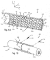
Fig. 1A is a perspective view of an expandable bone fixation implant configured in accordance with one embodiment; -
Fig. 1B is a perspective view of the expandable bone fixation implant illustrated inFig. 1A shown attached to an underlying bone; -
Fig. 1C is a sectional end elevation view of the expandable bone fixation implant illustrated inFig. 1A , attached to an underlying bone; -
Fig. 1D is a side elevation view of a portion of the implant body of the expandable bone fixation implant illustrated inFig. 1A , configured in accordance with an alternative embodiment; -
Fig. 2A is a perspective view of the expandable bone fixation implant illustrated inFig. 1A shown in a first collapsed configuration; -
Fig. 2B is a perspective view of the expandable bone fixation implant illustrated inFig. 1A shown in a second collapsed configuration; -
Fig. 3A is a sectional side elevation view of the expandable bone fixation implant illustrated inFig. 2A , including a pair of tethered bone screws; -
Fig. 3B is a sectional elevation view of a portion of an implant assembly including a portion of the expandable bone fixation implant, and other components; -
Fig. 4 is an enlarged sectional end elevation view of the expandable bone fixation implant as illustrated inFig. 1C , shown attached to an underlying bone; -
Fig. 5A is a perspective view of an expandable bone fixation implant constructed in accordance with an alternative embodiment; -
Fig. 5B is a perspective view of the expandable bone fixation implant illustrated inFig. 5A shown in a collapsed configuration; -
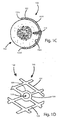
Fig. 5C is a sectional end elevation view of the expandable bone fixation implant illustrated inFig. 5A , attached to an underlying bone; -
Fig. 5D is a sectional elevation view of the expandable bone fixation implant illustrated inFig. 5C , constructed in accordance with an alternative embodiment and attached to an underlying bone; -
Fig. 5E is a sectional elevation view of the expandable bone fixation implant illustrated inFig. 5D , constructed in accordance with another alternative embodiment and attached to an underlying bone; -
Fig. 5F is a sectional elevation view of the expandable bone fixation implant illustrated inFig. 5E , configured in accordance with still another alternative embodiment and attached to an underlying bone; -
Fig. 6 is a perspective view of the expandable bone fixation implant illustrated inFig. 5A in a rolled configuration; -
Fig. 7 is a side elevation view of an implant assembly for use in a percutaneous fixation procedure whereby the expandable bone fixation implant illustrated ifFig. 1A is attached to a fractured rib bone; and -
Fig. 8 is a perspective view of the expandable bone fixation implant attached to fractured rib using the implant assembly illustrated inFig. 7 . - Certain terminology is used in the following description for convenience only and is not limiting. The words "right", "left", "top" and "bottom" designate directions in the drawings to which reference is made. The words "inward", "inwardly", "outward", "outwardly," "upward," "upwardly," "downward," and "downwardly" refer to directions toward or away from the geometric center of the device and/or designated parts thereof. The words, "anterior", "posterior", "superior", "inferior", "lateral", "medial", "sagittal", "axial", "coronal," "cranial," "caudal" and related words and/or phrases designate preferred positions and orientations in the human body to which reference is made and are not meant to be limiting. The terminology intended to be non-limiting includes the above-listed words, derivatives thereof and words of similar import.
- Referring initially to
Figs. 1A-D , a bone fixation device in the form of an expandablebone fixation implant 100 is configured to provide fixation and stabilization of an underlying bone during healing after a fracture, break, or other injury to abone 110, which can be a rib. For instance, thebone fixation implant 100 is configured to be attached to abone 110 that has sustained one or more fractures, such as afracture 112, that separates afirst bone segment 110a from asecond bone segment 110b. In particular, thefixation implant 100 is configured to be fixed to thebone 110 across thefracture 112 and to stabilize the fracturedbone segments 110a-b by fixing thebone segments 110a-b with respect to each other. Thefixation implant 100 is configured to be inserted minimally invasively into a body cavity of a patient that contains thebone 110 in an initial collapsed implantation configuration. Once thefixation implant 100 has been delivered to the implantation site, a percutaneous fixation procedure can be performed during which thefixation implant 100 can be expanded in the body cavity and positioned and fixed to thebone segments 110a-b on either side of thefracture 112, thereby stabilizing the injuredbone 110. - The expandable
bone fixation implant 100 includes animplant body 102 that extends along a longitudinal direction L, a lateral direction A that extends substantially perpendicular with respect to the longitudinal direction L, and a transverse direction T that extends substantially perpendicular to both the longitudinal direction L and the lateral direction A. Theimplant body 102 is elongate in the longitudinal direction L along a central longitudinal axis LL, defines a width in the lateral direction A, and defines a height in the transverse direction T. It should be appreciated that the longitudinal and lateral directions L and A, respectively, extend horizontally and the transverse direction T extends vertically in the orientation illustrated inFig. 1A . Accordingly, while certain directional terms are used herein to describe the expandablebone fixation implant 100 as illustrated for the purposes of clarity and convenience, it should appreciated that these orientations of the expandablebone fixation implant 100 may change during use. It should be further appreciated that theimplant body 102 extends radially outward along a radial direction R from the central longitudinal axis LL along a direction that can include both lateral and transverse directional components. - With continuing reference to
Fig. 1A , theimplant body 102 is resilient and expandable from a first collapsed configuration having a first outer cross-sectional dimension D1 (seeFigs. 2A-B ) to a second expanded configuration having a second outer cross-sectional dimension D2 that is greater than the first outer cross-sectional dimension D1. The first and second outer cross-sectional dimensions can be radial dimensions, for instance at least one or both of a height or a width. The first and second outer cross-sectional dimensions can be defined by a straight line that is substantially perpendicular to the longitudinal direction L, and can pass through the central longitudinal axis LL or be offset from the central longitudinal axis LL. Theimplant body 102 can also be collapsible from the second expanded configuration to the first collapsed configuration. In accordance with one embodiment, theimplant body 102 can be constructed of a resilient material having shape memory characteristics, such as nitinol or the like, but can also be constructed of any other biocompatible and/or bioresorbable material as desired, such as low grade titanium, commercially pure titanium, plastic, polyether ether ketone (PEEK), polyetherketoneketone (PEKK), polyglycolic acid (PGA), polylactic acid (PLA), polydioxanone (PDS), and the like. - Referring also to
Fig. 1B , theimplant body 102 is illustrated as defining a firstouter end 102a and a secondouter end 102b opposite the firstouter end 102a and spaced from substantially C-shaped when in the second expanded configuration, so as to define a first or uppertransverse edge 102c and a second or lowertransverse edge 102d that is spaced from the first or uppertransverse edge 102c along the transverse direction T (or the lateral direction A or combination of the lateral direction A and transverse direction T depending on the gap between theedges 102c-d and the orientation of the implant body 102). Thus, the upper and lowertransverse edges implant body 102 further defines a first or innerradial surface 102e and a second or outerradial surface 102f that is opposite the innerradial surface 102e and outwardly spaced from the innerradial surface 102f along the radial direction R. The inner, or bone-facing,surface 102e faces inwardly toward theunderlying bone 110 to which theimplant body 102 is attached, and theouter surface 102f faces outwardly away from theinner surface 102e. Theinner surface 102e of theimplant body 102 can be coated with bone morphogenic protein (BMP) or any other bone growth enhancing material, so as to enhance bone regrowth in the underlying bone. Theimplant body 102 can define the first and second outer dimensions as measured from radially opposed locations on theouter surfaces 102f along a straight line that can pass through the central longitudinal axis LL, or can alternatively be offset from the central longitudinal axis LL. - The
implant body 102 defines a radial thickness T that extends between the inner andouter surfaces 102e-f, respectively, along the radial direction R. Theimplant body 102 can be constructed having a substantially uniform thickness T throughout, for instance between the first andsecond ends 102a-b, and between the upper and lowertransverse edges 102c-d, respectively, as illustrated. Alternatively, theimplant body 102 can be constructed with one or more sections of varying thickness T, for example to induce desired deformation characteristics, strength, or the like into theimplant body 102. In a preferred embodiment, the thickness T of theimplant body 102 ranges from about 1 mm to 3 mm, and is preferably about 1.5 mm. - With continuing reference to
Figs. 1A-D , the expandablebone implant body 102 can be curved between the upper and lowertransverse edges 102c-d, so as to define a substantial C-shape that allows theinner surface 102e of theimplant body 102 to generally conform to the external surface of anunderlying bone 110. Theimplant body 102 can thus be curved about the longitudinal axis LL. In the illustrated embodiment, theimplant body 102 is substantially arc-shaped about the longitudinal axis LL between the upper and lowertransverse edges 102c-d, thus defining a generally "C-shaped," semi-tubular shape that is open between the upper and lowertransverse edges 102c-d. Otherwise stated, theimplant body 102 can be circumferentially discontinuous about the central longitudinal axis LL, so as to define a discontinuous outer perimeter P, when theimplant body 102 is in the expanded configuration. The arc-shaped curvature of theimplant body 102 can be defined by a radius R1 that extends along the radial direction R from the longitudinal axis LL to theinner surface 102e. In the illustrated embodiment, the length of the radius R1 can remain constant both with respect to the lateral direction around the longitudinal axis LL between the upper and lowertransverse edges 102c-d of theimplant body 102, and with respect to the length of theimplant body 102 as defined between the first and second outer ends 102a-b, such that the cross-sectional curvature of theimplant body 102 is uniform throughout theimplant body 102. It should be appreciated that the length of the radius R1 and/or the length of theimplant body 102 can be defined based on the anatomy of the intendedunderlying bone 110 to which the implant will be attached, the amount of surface area on theunderlying bone 110 to be fixedly enwrapped by theinner surface 102e of theimplant 100, and the like. - It should be appreciated that the
implant body 102 can also be configured such that the length of the radius R1 varies along one or more sections of theimplant body 102 with respect to the lateral direction around the longitudinal axis LL between the upper and lowertransverse edges 102c-d of theimplant body 102, and/or varies along one or more sections of the length of theimplant body 102, thereby defining animplant body 102 with non-uniform cross-sectional curvature. It should further be appreciated that although the illustrated embodiment of theimplant body 102 extends in a straight longitudinal direction between the first and second outer ends 102a-b, that theimplant body 102 can also be laterally curved between the first and second outer ends 102a-b, for instance with respect to one or more transverse axes, and/or can be transversely curved between the first and second outer ends 102a-b, for instance with respect to one or more lateral axes. Accordingly, it should be appreciated that theimplant body 102 can be configured using any combination of longitudinal, lateral, and/or transverse curvature, for example to ensure that contact between theinner surface 102e of theimplant body 102 and the outer surface of the underlying bone is optimized, thereby optimizing the stabilization and fixation provided by the expandablebone fixation implant 100 to the underlying bone. - The opening between the upper and
lower edges 102c-d can be spaced apart through a uniform or varying distance along the length of theimplant body 102, and the upper andlower edges 102c-d can be configured with any edge geometry as desired. For instance, the distance between the upper andlower edges 102c-d and the geometry of the edges can be configured based upon the amount of the outer surface of theunderlying bone 110 that should be encompassed within theimplant body 102, the presence of ligaments, muscles, and/or other bodily tissues that might obstruct contact between theimplant body 102 and the underlying bone, and other such considerations. It should therefore be appreciated that while the upper andlower edges 102c-d of the illustrated embodiment are substantially straight between the first andsecond ends 102a-b, respectively, that the upper andlower edges 102c-d can be configured with any alternate geometry as desired. It should further be appreciated that theimplant body 102 can be configured such that one or more sections, up to the entirety, of the length of the upper andlower edges 102c-d engage with each other when theimplant body 102 is attached to an underlying bone, and thus that one or more distinct openings between the upper andlower edges 102c-d, or no opening at all, can be defined. Moreover, it should be appreciated that one or more sections, up to the entirety, of the length of the upper andlower edges 102c-d, can be configured to overlap each other when theimplant body 102 is attached to an underlying bone, and further that one or more of the overlapping sections of the upper andlower edges 102c-d can be configured to complimentarily engage with each other. - The
implant body 102 includes a plurality of interconnected resilientflexible links 104 that can be integral and monolithic with each other as illustrated, or can alternatively be discreetly attached to each other. Thelinks 104 can be interconnected atintersections 109 in a repeating pattern to define a resilient, expandable and collapsible lattice or mesh 106 that defineopenings 111 in theimplant body 102. Themesh 106 can be defined throughout a substantial entirety of theimplant body 102 as illustrated, or alternatively can be defined in one or more distinct portions of theimplant body 102. In addition to allowing theimplant body 102 to be collapsed for implantation into a patient and subsequently expanded so as to conform to the outer surface of thebone 110 as described in more detail below, once theimplant body 102 has been attached thebone 110, themesh 106 allows for bony in-growth during the healing process of thebone 110. It should be appreciated that while thelinks 104 are diamond shaped in accordance with the illustrated embodiment, thelinks 104 can define any suitable alternative geometry as desired. It should be further appreciated that thelinks 104 can be symmetrical or asymmetrical with respect to each other and can be arranged in a repeating or variable pattern, as illustrated, and that theimplant body 102 can be constructed with any combination of differing link geometries and/or interconnection patterns as desired. - Referring now to
Figs. 1A and2A-B , thelinks 104 can be configured asresilient links 104 such that thelinks 104 can be at least partially collapsed upon themselves, thereby allowing theimplant body 102 to be operatively expanded and contracted between an expanded, or neutral, configuration as illustrated inFig. 1A , and a contracted, or collapsed, configuration as illustrated inFigs. 2A-B . The collapsed configuration displaces a smaller volume than the expanded configuration, such that theimplant body 102 can be implanted into a patient when in the collapsed configuration, for example via a catheter, as described in more detail below. Otherwise stated, theimplant body 102 defines a larger cross section in the expanded configuration than in the collapsed configuration. For instance, when the implant body is in the expanded configuration, theopenings 111 define a first circumferential or tangential dimension, and when the implant body is in the collapsed configuration, theopenings 111 define a second circumferential or tangential dimension that is less than the first circumferential or tangential dimension. - Referring to
Fig. 2A , theimplant body 102 is radially collapsible from an expanded configuration to a collapsed configuration, such that the upper and lowertransverse edges 102c-d abut each other and a hollow channel 108 extends through theimplant body 102 from the first through the second ends 102a-b, respectively, along the longitudinal direction. The hollow channel 108 can be encircled by theimplant body 102. Alternatively, the upper and lowertransverse edges 102c-d can be spaced apart so as to define a circumferential or tangential opening therebtween when theimplant body 102 is in the collapsed configuration (seeFig: 3A ). Theimplant body 102 can then be iterated from the collapsed configuration illustrated inFig. 2A to an expanded configuration by expanding anexpandable bladder 126, such as a bladder that is disposed in the channel 108 as described in more detail below (seeFig. 3B ). Alternatively still, referring toFig. 2B , thetransverse edges 102c-d can be disposed past each other so as to define a smaller encircled channel 108 than when thetransverse edges 102c-d abut each other. For instance, theimplant body 102 can be radially collapsed and rolled upon itself into the collapsed configuration. Theimplant body 102 can define an initial collapsed configuration prior to implantation, or can define an initial expanded configuration that can be collapsed prior to implantation. Thus, theimplant body 102 can be relaxed in the expanded configuration. Theimplant body 102 can be iterated from the collapsed configuration illustrated inFig. 2B to the expanded configuration with the use of one or more percutaneously inserted tools or instruments, such as a grasper tool or a mandrel, as described in more detail below. - It should be appreciated that depending upon what material is used to construct the
implant body 102, that theimplant body 102 may have shape memory characteristics such that theimplant body 102 can expand at least partially, or completely unassisted, from the collapsed configuration to the expanded configuration, for instance when theimplant body 102 is removed from a delivery sheath after being inserted into a patient. It should further be appreciated that the collapsed configurations of theimplant body 102 are not meant to be limited to the example collapsed configurations depicted inFigs. 2A-B , and that theimplant body 102 can be configured with any alternative collapsed configuration as desired. - Referring to
Figs. 1A-D andFig. 7 generally, animplant assembly 200 can include theimplant body 102, an implantation assembly including aninsertion instrument 400, asecond instrument 500 that is can be configured as a bone screw dispensing and/or bone screw driving tool or a second grasper tool, acatheter 300, and a plurality of fasteners, including one or more bone anchors 114 illustrated as bone screws 116 that are configured to fix theimplant body 102 to an underlying structure, such as thebone 110. Of course the bone anchors 114 can be provided as any other type of fastener as desired. The bone anchors 114 can be percutaneously or otherwise be delivered to the location where theimplant body 102 will be attached to theunderlying bone 110 and driven into place via a bone screw dispensing and/or driving tool (not shown). - Referring to
Figs. 1A-D and3A-B , according to one embodiment, the bone anchors 114 can be bone screws that are tethered to theimplant body 102, and thus designed to be permanently attached to theimplant body 102. Accordingly, the implant body is attached to thebone 110 when the bone anchors 114 are affixed to thebone 110, as described in more detail below. Alternatively, theimplant body 102 and/or the bone anchors 114 can be configured such that the bone anchors 114 can be removably coupled to theimplant body 102 during implantation of theimplant body 102 onto thebone 110. For example, the heads of the bone anchors 114 can be configured to be press fit to the ends of theimplant body 102, or the bone anchors 114 can be configured to be received in complimentary retaining structures defined on theimplant body 102, such as complimentary slots or grooves. - In accordance with the illustrated embodiment, the bone screws 116 can be at least partially disposed in the openings provided by the
links 104 at any location on theimplant body 102 and driven into place within theunderlying bone 110. Alternatively, theimplant body 102 can be configured with a plurality ofbone attachment locations 120. As depicted inFig. 1D , thebone attachment locations 120 are provided as screw holes 118 extending laterally through theimplant body 102, for instance at one or more of theintersections 109. It should be appreciated that while thebone attachment locations 120 are depicted as being located at theintersections 109 of adjacentinterconnected links 104, that thebone attachment locations 120 can be located anywhere on theimplant body 102 as desired. - The screw holes 118 can be sized to threadedly or nonthreadedly receive corresponding fasteners or bone anchors 114, such as the bone screws 116. Specifically, referring to
Fig. 4 , eachbone attachment location 120 on theimplant body 102 can include a beveledinner surface 122 that defines thescrew hole 118, and is sized and shaped to receive a correspondingly beveled inwardly facingsurface 119 of thescrew head 117 of abone screw 116. Thebeveled surface 122 is positioned such that the outwardly facing surface of thescrew head 117 aligns with theouter surface 102f of theimplant body 102 when thescrew head 117 is fully seated in thescrew hole 118. As illustrated, thescrew head 117 is flush with theouter surface 102f of theimplant body 102, though thescrew head 117 could alternatively be inwardly recessed or slightly outwardly protruding with respect to theouter surface 102f of theimplant body 102. Accordingly, thescrew head 117 can compress theimplant body 102 against theunderlying bone 110. It should be appreciated that thescrew hole 118 can assume any one of numerous configurations. For example theinner surface 122 can be beveled, straight, or can be rounded at any desired radius. In another example configuration, theinner surface 122 can be threaded, the threads configured to engage complimentary threads formed on the inwardly facingsurface 119 of thescrew head 117, such that thebone screw 116 is self-locking within thescrew hole 118. It should also be appreciated that the bone screws 116 can be self-drilling, or can alternatively be insertable into pre-drilled holes. - Referring now to
Figs. 3A-B ,the.implant 100 can include the bone screws 116 tethered to theimplant body 102 such that the bone screws 116 are implanted along with theimplant body 102. Tethering the bone screws 116 to theimplant body 102 can prevent perioperative or subsequent loss of the bone screws 116 in the patient's body. In the illustrated embodiment, the bone screws 116 are tethered to theimplant body 102 viatethers 103. Thetethers 103 can be constructed with any desired structure, such as a solid wire, flexible rod, a plurality of linked segments, and the like, and can be constructed of any appropriate biocompatible material, including non-bioresorbable materials such as nitinol, nylon, polypropylene, and the like, or bioresorbable materials such as polyglycolic acid (PGA), polylactic acid (PLA), polydioxanone (PDS), and the like. - The illustrated tethers 103 define proximal ends 103a that are connected to the bone screws 116 and distal ends 103b that are opposite the proximal ends 103a and connected to the
implant body 102. Theimplant body 102 can be constructed such that the distal ends 103b of thetethers 103 are integral and monolithic with theimplant body 102 at desired locations along its length, such that thetethers 103 and/or respective bone screws 116 are components of the expandablebone fixation implant 100. Alternatively, thetethers 103 can be attached to the bone screws 116 and to desired locations on theimplant body 102 when theimplant 100 is implanted. Alternatively still, the bone screws 116 can be provided with thetethers 103 pre-attached to the bone screws 116, and the distal ends 103b of thetethers 103 can be attached to desired locations on theimplant body 102 at the time of implantation. It should be appreciated that thetethers 103 can be attached to theimplant body 102 when theimplant body 102 is in either the collapsed configuration or the expanded configuration. Thetethers 103 can be of any length sufficient to allow insertion of abone screw 116 through a respective desired location on theimplant body 102 and into the underlying bone. - In the illustrated embodiment, the
tethers 103 have attachment rings 105 coupled to theirproximal ends 103a. The attachments rings 105 are configured to be disposed incomplimentary grooves 115 defined in the bone screws 116. The attachment rings 105 and thegrooves 115 are complimentarily sized such that the bone screws 116 are free to rotate with respect to thetethers 103 when the attachment rings 105 are disposed in thegrooves 115. - Referring now to
Fig. 3B , the expandablebone fixation implant 100,tethers 103 and/or respective bone screws 116 can be combined with various other components of theimplant assembly 200. For example, theimplant body 102 can be iterated to the collapsed configuration as depicted, and inserted, along with a pair of tethered bone screws 116, into aflexible sheath 124, such as that of acatheter 300. Theimplant assembly 200 can include an expansion device, such as expandableinflatable bladder 126 illustrated as an inflatable balloon, disposed within theimplant body 102, for instance in the channel 108, and configured to iterate theimplant body 102 from the collapsed configuration to the expanded configuration after theimplant body 102 has been implanted. The expansion device can also be provided as a mandrel (not shown) disposed within thecollapsed implant body 102. After the platedbody 102 has been implanted, the mandrel can be pulled trough theimplant body 102, for instance from thesecond end 102b to thefirst end 102a, thereby iterating theimplant body 102 from the collapsed configuration to the expanded configuration. Theimplant assembly 200 can further include aguide wire 128 disposed within thebladder 126, and thus theimplant body 102 and thesheath 124, as illustrated. Theguide wire 128 can lend rigidity to theimplant assembly 200 and assist a surgeon in guiding theimplant assembly 200 into a target location in a patient's body. - The bone screws 116 may be specifically configured for use with the
implant body 102. For instance, as illustrated, respective first and second bone screws 116 are tethered to theimplant body 102 and disposed at the first andsecond ends 102a-b of theimplant body 102, respectively. Thesecond bone screw 116, disposed at thesecond end 102b of theimplant body 102, includes alongitudinal bore 121, thebore 121 configured to receive theguide wire 128 therein. In thefirst bone screw 116, disposed at the first end of theimplant body 102, thebore 121 can be extended throughout the entire longitudinal length of thebone screw 116, such that theguide wire 128 can be inserted through thefirst bone screw 116, through thebladder 126, and into thebore 121 of thesecond bone screw 116. - Referring again to
Fig. 1A , theimplant body 102 can include additional securement structures to enhance engagement between theinner surface 102e of theimplant body 102 and the outer surface of the underlying bone to which theimplant body 102 is attached. For example, theimplant body 102 can include at least one grip member 102g , such asspikes 107, that extend radially inward from theinner surface 102e toward the central longitudinal axis LL. It should be appreciated that the grip members 102g can be provided on one or more sections, up to the entirety, of theinner surface 102e of theimplant body 102, as desired. The grip members 102g, and in particular thespikes 107 of the illustrated embodiment, can be configured to engage or bite into underlying structure, such as the outer surface of theunderlying bone 110. The grip members 102g can increase the surface area of theinner surface 102e which can be coated with bone growth enhancing materials such as BMP. Of course, theimplant 100 can include any bone growth enhancing coating applied to a portion of theinner surface 102e, for instance at distinct areas of theinner surface 102e, up to the entirety of theinner surface 102e, as desired. - The
implant body 102 can include additional or alternative securement structures along the upper and lowertransverse edges 102c-d. For example, one or more grip members, such as teeth, can extend inwardly from the upper and/or lowertransverse edges 102c-d in a direction towards the underlying bone, the teeth configured to engage the outer surface of the underlying bone. The teeth can be constructed so as to remain in a fixed position with respect to theimplant body 102, or alternatively can be constructed so as to fold out, or otherwise be iterated to a deployed configuration, after implantation of theimplant body 102. - Referring now to
Figs. 5A-F , the expandablebone fixation implant 100 can include animplant body 202 constructed in accordance with an alternative embodiment. Theimplant body 202 is illustrated as defining opposed first and second longitudinally outer ends 202a and 202b, opposed upper and lowerlongitudinal edges lateral surfaces surface 202e faces inwardly toward an underlying bone to which theimplant body 202 is attached, and theouter surface 202f faces outwardly away from theinner surface 202e. The bone-facingsurface 202e of theimplant body 202 can be coated with BMP or other bone growth enhancers as desired. Theimplant body 202 defines a lateral thickness T between the inner andouter surfaces 202e-f, respectively. Theimplant body 202 can be constructed having uniform thickness T throughout, for instance between the first andsecond ends 202a-b, respectively and between the upper andlower edges 202c-d, respectively, as illustrated. Alternatively, theimplant body 202 can be constructed with one or more sections of varying thickness T, for example to induce desired deformation characteristics, strength, or the like into theimplant body 202. In a preferred embodiment, the thickness T of theimplant body 202 ranges from about 1 mm to 3 mm, and is preferably about 1.5 mm. - The
implant body 202 includes a plurality of interconnectedresilient links 204 that can be integrally connected as illustrated, or can alternatively be discreetly attached to each other. Thelinks 204 can be interconnected in a repeating pattern to define a resilient lattice, ormesh 206, in theimplant body 202. Themesh 206 can be defined throughout substantially the entirety of theimplant body 202 as illustrated, or alternatively can be defined in one or more distinct portions of theimplant body 202. Themesh 206 can be configured to influence the flexibility of theimplant body 202 and thus the ability of theinner surface 202e of theimplant body 202 to conform to the outer surface of an underlying bone. It should be appreciated that while thelinks 204 in the illustrated embodiment are triangle shaped, that any other geometry can be used for thelinks 204 as desired. It should be further appreciated that thelinks 204 need not be symmetrical with respect to each other as illustrated, or be arranged in a repeating pattern, and that theimplant body 202 can be constructed with any combination of differing link geometries and/or interconnection patterns as desired. - The
implant body 202 can be attached, or secured, to an underlying structure, such as anunderlying bone 110, with one or more fasteners or bone anchors 114, such as the bone screws 116 illustrated inFigs. 1A-D andFig. 4 . Of course any other type of fastener orbone anchor 114 can be used as desired. The bone screws 116 can be implanted and driven into theunderlying bone 110 via any suitable bone screw dispensing and/or driving tool. Alternatively, the bone screws 116 can be tethered bone screws that are integrally connected or otherwise coupled to theimplant body 202, as described above with reference toFigs. 3A-B . In accordance with the illustrated embodiment, the bone screws 116 can be at least partially disposed in openings in themesh 206 at any location on theimplant body 202 and driven into place theunderlying bone 110. Alternatively, theimplant body 202 can include a plurality of bone attachment locations, as described above with reference toFig. 1D . Similarly the bone attachment locations can be provided as screw holes extending laterally through theimplant body 202, as described above with reference toFig. 4 , and can be located anywhere on theimplant body 202 as desired. It should be appreciated that when theimplant body 202 is attached to an underlying bone, that themesh 206 can allow for bony in-growth during the healing process of the bone. - The
implant body 202 further includes alongitudinal folding edge 201 defined along the longitudinal direction L between the first andsecond ends 202a-b, respectively. Thefolding edge 201 longitudinally divides theimplant body 202 into first andsecond plate segments 208 that can be equally dimensioned as illustrated. Thefolding edge 201 allows theimplant body 202 to be iterated between the expanded configuration illustrated inFig. 5A and the collapsed configuration illustrated inFig. 5B for implantation into a patient. In the illustrated embodiment, thefolding edge 201 is defined between the first andsecond ends 202a-b, respectively, substantially along the midline of theimplant body 202 as defined between the upper andlower edges 202c-d. It should be appreciated that thefolding edge 201 can be alternatively be defined at any desired location between the upper andlower edges 202c-d as desired. - When the
implant body 202 of the illustrated embodiment is in the collapsed configuration, theimplant body 202 is folded substantially in half around thefolding edge 201 such the first andsecond plate segments 208 abut each other, thus aligning the upper andlower edges 202c-d. It should be appreciated that the folding edge can be located anywhere along the implant body as desired. The collapsed configuration displaces a smaller volume than the expanded configuration, such that theimplant body 202 can be implanted into a patient when in the collapsed configuration, for example inside a catheter. Theimplant body 202 can define at least one groove such as a plurality ofgrooves 203 that extend into the inner orouter surfaces 202e-f along thefolding edge 201. Thegrooves 203 can be define hinges that enhance the collapsibility of theimplant body 202. Thegrooves 203 can be defined along one or more sections, up to the entirety of thefolding edge 201, and can be defined in theinner surface 202e and/or theouter surface 202f in any combination as desired. - Referring now to
Figs. 5C-F , theimplant body 202 can define one or morefolding edges 201 and/or correspondinggrooves 203, as desired. Theimplant body 202 depicted inFig. 5C has asingle folding edge 201 and a pair ofcorresponding grooves 203, thereby defining twoplate segments 208 and thus two areas of contact between theinner surface 202e of theimplant body 202 and the outer surface of theunderlying bone 110. However, configuring theimplant body 202 with a plurality offolding edges 201, thereby definingadditional plate segments 208, can allow theimplant body 202 to better conform to the outer surface of underlying structure, such as theunderlying bone 110, for instance by providing more contact area between theinner surface 202e of theimplant body 202 and the outer surface of theunderlying bone 110. For example, theimplant body 202 depicted inFig. 5D has twofolding edges 201 andcorresponding grooves 203, thereby defining three equallydimensioned plate segments 208 and thus three areas of contact between theinner surface 202e of theimplant body 202 and the outer surface of theunderlying bone 110. In another example, theimplant body 202 depicted inFig. 5E has threefolding edges 201 andcorresponding grooves 203, thereby defining four equallydimensioned plate segments 208 and thus four areas of contact between theinner surface 202e of theimplant body 202 and the outer surface of theunderlying bone 110. - It should be appreciated that the folding edges 201 can be spaced equally or unequally apart from each other between the upper and
lower edges 202c-d of theimplant body 202, and thus that theplate segments 208 defined by the folding edges can be equally or differently dimensioned. For example, theimplant body 202 depicted inFig. 5F has sevenfolding edges 201 andcorresponding grooves 203, thereby defining eightplate segments 208 and thus eight areas of contact between theinner surface 202e of theimplant body 202 and the outer surface of theunderlying bone 110. However, theoutermost plate segments 208 located at the upper andlower edges 202c-d, respectively, have a greater lateral width than the sixinner plate segments 208. It should further be appreciated that theimplant body 202 can be configured with any number offolding edges 201 defined at any desired locations between the upper andlower edges 202c-d of theimplant body 202, thereby definingplate segments 208 having any combination of lateral widths as desired. It should be appreciated that the number offolding edges 201, the location of the folding edges 201 with respect to the upper andlower edges 202c-d of theimplant body 202, the lateral distance between the upper andlower edges 202c-d when theimplant body 202 is in the expanded configuration, and/or the length of theimplant body 202 can be defined based on the anatomy of the intendedunderlying bone 110 to which the implant will be attached, the amount of surface area on theunderlying bone 110 to be fixedly enwrapped by theinner surface 202e of theimplant 100, and the like. - The
implant body 202 can be iterated from the expanded configuration to the collapsed configuration before implantation, or can initially be provided in the collapsed configuration. Alternatively, theimplant body 202 can be provided in the collapsed configuration. Theimplant body 202 can be implanted into a patient using various techniques. In one example, theimplant body 202 can be delivered into the patient's body using a sheath, such as that of a catheter, and iterated to the expanded configuration after the sheath is removed from theimplant body 202. Alternatively, theimplant body 202 can be iterated to its collapsed configuration and rolled upon itself in the longitudinal direction L, defining a rolled implant body 210 as illustrated inFig. 6 . The rolled implant body 210 can then be implanted and subsequently unrolled and iterated to the expanded configuration. It should be appreciated that theimplant body 202 can also be provided as a rolled implant body 210. When provided as a rolled implant body 210, theimplant body 202 can be cut from the rolled implant body 210 in a desired length and implanted into a patient using any suitable implantation method. It should further be appreciated the techniques described above for implantation of theimplant body 202 and the rolled implant body 210 are merely examples, and that any method of implanting theimplant body 202 and/or the rolled implant body 210 can be employed as desired. - Referring again to
Figs. 5A-F , once theimplant body 202 has been implanted into a patient's body and/or maneuvered into position for attachment to an underlying bone, theimplant body 202 can be iterated from the collapsed configuration illustrated inFig. 2B to its expanded configuration with the use of a grasper tool, as described in more detail below. It should be appreciated that depending upon what material that is used to construct theimplant body 202, that theimplant body 202 may have shape memory characteristics such that theimplant body 202 can expand at least partially, or completely unassisted, from the collapsed configuration to the expanded configuration, for instance when theimplant body 202 is removed from a delivery sheath after being implanted. It should further be appreciated that the collapsed configurations of any of theplate bodies 202 depicted inFigs. 5D-F can be configured differently from the collapsed configuration depicted inFig. 5B , for example in accordance with the number offolding edges 201 and the lateral widths of theplate segments 208. - The
implant body 202 can be configured with additional securement structures to enhance engagement between theinner surface 202e of theimplant body 202 and the outer surface of the underlying bone to which theimplant body 202 is attached. The securement structures can include the grip members described above with respect to theimplant body 102, or any other securement structures as desired. Additionally, distinct areas of theinner surface 102e, up to the entirety of theinner surface 202e of theimplant body 202, can be coated with bone growth enhancing materials, such as BMP, or the like. - Referring now to
Figs. 7-8 , in operation, the expandablebone fixation implant 100 can be used for percutaneous or suitable alternative bone fixation procedures as desired. For example, a minimally invasive percutaneous bone fixation procedure can be performed in which a expandablebone fixation implant 100 is attached to an injuredunderlying bone 110, such as a rib that has sustained afracture 112. An expandablebone fixation implant 100 appropriate for the particular procedure can be selected, such as afixation implant 100 with theimplant body 102. If theimplant body 102 was not provided in its collapsed configuration, theimplant body 102 can be iterated to its collapsed configuration in preparation for implantation. - A desired number of incisions, or ports, are made into appropriate locations of the patient's body. In the illustrated procedure, a first incision I1 is made to allow implantation of the expandable
bone fixation implant 100 into the patient inside a catheter. A second incision I2 is made to allow the insertion of aninstrument 400 configured with a camera, such as an endoscope. The endoscope can also be configured with a grasper component configured to operate theimplant body 102 from the collapsed configuration to the expanded configuration and/or to maneuver theimplant body 102 into position for attachment to theunderlying bone 110. A third incision I3 can be made to allow the insertion of anotherinstrument 500, such as a bone screw dispensing and/or driving tool or a second grasper tool. It should be appreciated that the number and locations of incisions illustrated and described herein are illustrative of a particular example fixation procedure, and that more or fewer incisions can be made at any location on a patient's body, depending for example upon the type of fixation procedure being performed. - The
implant body 102, in its collapsed configuration, can be combined with a pair of tethered bone screws 116, aninflatable bladder 126, and aguide wire 128 in animplant assembly 200 and disposed within thesheath 124 of thecatheter 300. It should be appreciated that theimplant assembly 200 can be otherwise configured as described above. Thecatheter 300 may be selected based upon the volume displaced by theimplant assembly 200, the type of implant body being implanted (e.g., 102, 202), whether the implant body is being implanted in the expanded or collapsed configuration, and so on, but will typically be selected from a range between a 4mm (12 Fr) size to an 8mm (24 Fr) size catheter. Thecatheter 300 can be inserted into the first incision or port and maneuvered into position in the vicinity of the underlying bone to which theimplant body 102 is to be attached. As illustrated, theunderlying bone 110 is the sixth rib, which has sustained afracture 112. It is desirable to attach theimplant body 102 to theunderlying bone 110 such that both of the fracturedbone segments 110a-b are encompassed by theimplant body 102. - When the
catheter 300 is positioned as desired, thesheath 124 can be retracted from theimplant assembly 200, or theimplant assembly 200 can otherwise be removed from thesheath 124, for example with the grasper tools of theinstruments 400 and/or 500. Theimplant body 102 can then be iterated from the collapsed configuration to the expanded configuration. Theimplant body 102 can be iterated into its expanded configuration by inflating thebladder 126, may be operated into the expanded configuration through the use of theinstruments 400 and/or 500, may expand to the expanded configuration at least partially due to shape memory characteristics of the material it is constructed from, or any combination thereof. Of course any additional securement structures, such as the above-described teeth, can be operated into their respective deployed configurations. - Once iterated to the expanded configuration, the
implant body 102 can be further maneuvered into a final attachment position and secured to theunderlying bone 110, for example via the grasper of one or more of theinstruments 400 and/or 500, and placed into engagement with theunderlying bone 110. The grasper of theinstruments 400 and/or 500 can also be used to position the tethered bone screws 116 at desired locations so that they can be driven into theunderlying bone 110 with the use of a driving instrument, thereby attaching, or securing, theimplant body 102 to theunderlying bone 110. Alternatively, if theimplant body 102 of theimplant assembly 200 is provided without tethered bone screws 116, the bone screws 116 can be dispensed, positioned, and/or driven into place by an instrument, such as a bone screw dispensing and/or driving tool. It should be appreciated that even if theimplant body 102 is provided without tethered bone screws 116, that tethered bone screws 116 can still be employed in the fixation procedure. For example, the tethered bone screws 116 can be implanted via a separate instrument, and the distal ends 103b of thetethers 103 can be anchored to theimplant body 102 and/or to surrounding structure, such as theunderlying bone 110. It should further be appreciated that a single instrument or tool can be configured with the above-described grasper and bone screw dispensing and/or driving components. - The above-described fixation procedure can be similarly performed using a expandable
bone fixation implant 100 configured with theimplant body 202. It should be appreciated that the expandablebone fixation implant 100 is suitable for use in procedures other than a percutaneous fixation procedure. For example, the expandable bone fixation implant can be used as a supplementary fixation device with other types of bone plates, implants, and the like, or can be used in a prophylactic manner, for example to prevent further damage to hairline and/or stress fractures. It should further be appreciated that the expandablebone fixation implant 100 is suitable for use in stabilizing and providing fixation to underlying bones other than rib bones, for instance bones such as the ulna, the fibula, the clavicle, and the like. - It should be appreciated that components of the expandable
bone fixation implant 100 and/or theimplant assembly 200 can be provided in a variety of fixation kits. The components of the kits may be configured the same or differently. For example, within a single kit,plate bodies 102 and/or 202 can be provided that have varying lengths, mesh structures, curvatures, numbers of folding edges. Furthermore, theplate bodies 102 and/or 202 and can be provided with or without tethered bone screws having tethers of varying lengths, depending for example on the type of fixation procedure being performed. The kits may also be configured differently with respect to which components are included in the kits. For example, kits can be provided having any combination of the above-described components of theimplant assembly 200 and/or any combination of the above-described instruments, ortools implant assembly 200 and/or any combination of the above-described instruments, or tools 300,400, and 500. - Although the expandable
bone fixation implant 100 and theimplant assembly 200 have been described herein with reference to preferred embodiments or preferred methods, it should be understood that the words which have been used herein are words of description and illustration, rather than words of limitation. For example, it should be appreciated that the structures and/or features of components of theimplant body 102 may be combined with or otherwise integrated with the structures and/or features of theimplant body 202, unless otherwise indicated. Furthermore, it should be noted that although the expandablebone fixation implant 100 and theimplant assembly 200 have been described herein with reference to particular structure, methods, and/or embodiments, the scope of the instant disclosure is not intended to be limited to those particulars, but rather is meant to extend to all structures, methods, and/or uses of the expandablebone fixation implant 100 and theimplant assembly 200. Those skilled in the relevant art, having the benefit of the teachings of this specification, may effect numerous modifications to the expandablebone fixation implant 100 and theimplant assembly 200 as described herein, and changes may be made without departing from the scope of the instant disclosure, for instance as recited in the appended claims.
Claims (15)
- A bone fixation implant (100) comprising:an implant body (102; 202) that extends along a longitudinal axis (LL) between first and second opposed ends (102a, 102b; 202a, 202b), the implant body (102; 202) including a plurality of interconnected resilient links (104; 204) that define a bone-facing surface (102e; 202e) and an opposed outer surface (102f; 202f),wherein the resilient links (104; 204) are configured such that the implant body (102; 202) is operable between a collapsed configuration whereby the implant body (102; 202) defines a first outer cross-sectional dimension (D1) and an expanded configuration, wherein the implant body (102; 202) defines a second outer cross-sectional dimension (D2) that is greater than the first outer cross-sectional dimension (D1), such that the implant body (102; 202) is configured to be implanted into a body cavity in the collapsed configuration and fixed to an underlying bone (110) in the body cavity in the expanded configuration,characterized in that the implant (100) further comprises at least one bone anchor (114) tethered to the implant body (102; 202).
- The bone fixation implant as recited in claim 1, wherein the implant body (102; 202) is open between opposed upper and lower edges (102c, 102d; 202c, 202d) that move relative to each other as the implant body (102; 202) is iterated between the collapsed and expanded configurations.
- The bone fixation implant as recited in claim 1 or 2, wherein the implant body (102) is radially collapsible about the longitudinal axis (LL).
- The bone fixation implant as recited in claim 1 or 2, wherein the implant body (202) is transversely collapsible upon itself around a longitudinal folding edge (201).
- The bone fixation implant as recited in any one of claims 1 to 4, wherein the implant body (102; 202) further comprises a plurality of bone attachment locations (120).
- The bone fixation implant as recited in any one of claims 1 to 3, wherein the implant body (102) is curved around the longitudinal axis (LL) between the first and second ends (102a, 102b).
- The bone fixation implant as recited in any one of claims 1 to 6, wherein the bone-facing surface (102e; 202e) has a plurality of securement structures (102g) formed thereon, the securement structures (102g) configured to engage the underlying bone (110).
- The bone fixation implant as recited in any one of claims 1 to 7, wherein the bone-facing surface (102e; 202e) is coated with a bone-growth enhancing material.
- The bone fixation implant as recited in any one of claims 1 to 8, wherein the first and second cross-sectional dimensions (D1, D2) extend along a straight line that passes through the longitudinal axis (LL).
- The bone fixation implant as recited in claim 9, wherein the longitudinal axis (LL) is a central longitudinal axis.
- A bone fixation kit comprising first and second bone fixation implants as recited in any one of claims 1 to 10, wherein
the first bone fixation implant (100) extends along a first longitudinal axis (LL) so as to define a first length defined between a first end (102a; 202a) of the first bone fixation implant (100) and a second end (102b; 202b) of the first bone fixation implant (100) along the longitudinal axis (LL), the first bone fixation implant (100) including a first plurality of interconnected resilient links (104; 204); and
the second bone fixation implant (100) extends along a second longitudinal axis (LL) so as to define a second length defined between a first end (102a; 202a) of the second bone fixation implant (100) and a second end (102b; 202b) of the second bone fixation implant (100) along the second longitudinal axis (LL), the second bone fixation implant (100) including a second plurality of interconnected resilient links (104; 204); the bone fixation kit further comprising:a plurality of bone anchors (114) configured to attach the first and second bone fixation implants (100) to one or more respective underlying bones (110),wherein the first and second pluralities of resilient links (104; 204) are configured such that the first and second bone fixation implants (100) are expandable from a collapsed configuration to an expanded configuration, whereby the first and second bone fixation implants (100) define an outer cross-sectional dimension (D2) in the respective expanded configurations that is greater than an outer cross-sectional dimension (D1) when in the respective collapsed configurations, such that the first and second bone fixation implants (100) are configured for implantation into a patient in the collapsed configuration and expandable for attachment to the respective one or more underlying bones (110). - The bone fixation kit as recited in claim 11, wherein the first and second lengths are different.
- The bone fixation kit as recited in claim 11 or 12, wherein at least one of the plurality of bone anchors (114) are tethered to at least one of the first and second bone fixation implants (100).
- The bone fixation kit as recited in any one of claims 11 to 13, wherein at least one of the first and second bone fixation implants (100) is radially collapsible about a respective longitudinal axis (LL).
- The bone fixation kit as recited in any one of claims 11 to 13, wherein at least one of the first and second bone fixation implants (100) is transversely collapsible upon itself around a respective longitudinal folding edge (201).
Applications Claiming Priority (2)
| Application Number | Priority Date | Filing Date | Title |
|---|---|---|---|
| US201161436028P | 2011-01-25 | 2011-01-25 | |
| PCT/US2012/022465 WO2012103164A1 (en) | 2011-01-25 | 2012-01-25 | Expandable bone fixation implant |
Publications (2)
| Publication Number | Publication Date |
|---|---|
| EP2667809A1 EP2667809A1 (en) | 2013-12-04 |
| EP2667809B1 true EP2667809B1 (en) | 2015-11-04 |
Family
ID=45561144
Family Applications (1)
| Application Number | Title | Priority Date | Filing Date |
|---|---|---|---|
| EP12702139.2A Not-in-force EP2667809B1 (en) | 2011-01-25 | 2012-01-25 | Expandable bone fixation implant |
Country Status (4)
| Country | Link |
|---|---|
| US (1) | US8906074B2 (en) |
| EP (1) | EP2667809B1 (en) |
| CA (1) | CA2825198C (en) |
| WO (1) | WO2012103164A1 (en) |
Cited By (1)
| Publication number | Priority date | Publication date | Assignee | Title |
|---|---|---|---|---|
| US20200316258A1 (en) * | 2016-09-29 | 2020-10-08 | University Of Southern California | Growth factor transduced cell-loaded ceramic scaffold for bone regeneration and repair |
Families Citing this family (23)
| Publication number | Priority date | Publication date | Assignee | Title |
|---|---|---|---|---|
| WO2010080511A1 (en) | 2008-12-18 | 2010-07-15 | 4-Web Spine, Inc. | Truss implant |
| BR112012022686B1 (en) | 2010-03-10 | 2021-04-20 | Oss-Q Ab | mosaic implant, method for preparing an implant and using an implant |
| US9463046B2 (en) | 2011-08-22 | 2016-10-11 | Ossdsign Ab | Implants and methods for using such implants to fill holes in bone tissue |
| US9414873B2 (en) * | 2012-01-05 | 2016-08-16 | The Cleveland Clinic Foundation | Modular bone fixation system |
| US9452005B2 (en) | 2012-08-23 | 2016-09-27 | DePuy Synthes Products, Inc. | Bone fixation system |
| US10004603B2 (en) | 2012-08-23 | 2018-06-26 | DePuy Synthes Products, Inc. | Bone implant |
| IN2015DN01971A (en) | 2012-08-23 | 2015-08-14 | Synthes Gmbh | |
| CA2889063C (en) | 2012-09-25 | 2021-10-26 | 4Web, Inc. | Programmable implants and methods of using programmable implants to repair bone structures |
| WO2014125381A2 (en) | 2013-02-12 | 2014-08-21 | Ossdsign Ab | Mosaic implants, kits and methods for correcting bone defects |
| US9220597B2 (en) * | 2013-02-12 | 2015-12-29 | Ossdsign Ab | Mosaic implants, kits and methods for correcting bone defects |
| US9486330B2 (en) | 2013-03-01 | 2016-11-08 | Bones And Spine Surgery Inc. | Minimally invasive method and surgical tools for trans-PSOAS approach |
| CA2911880C (en) * | 2013-03-15 | 2022-02-08 | 4-Web, Inc. | Traumatic bone fracture repair systems and methods |
| BR112015028601A2 (en) * | 2013-05-15 | 2017-07-25 | Pius Noetzli Hubert | implant for fixation to the bone by pressure |
| US10206781B2 (en) * | 2014-05-13 | 2019-02-19 | The University Of Akron | Modular device for preventing compression and instability in a segmental defect repair scaffold |
| JP6600680B2 (en) | 2014-08-14 | 2019-10-30 | オスディーサイン アーベー | Bone implant for bone defect correction |
| JP5807885B1 (en) * | 2014-09-24 | 2015-11-10 | 圓井繊維機械株式会社 | Bone fixing device and manufacturing method thereof |
| WO2016123060A1 (en) * | 2015-01-26 | 2016-08-04 | Brigham Young University | Compliant vertebral attachment device |
| US9936991B2 (en) * | 2015-01-30 | 2018-04-10 | Union Surgical, Llc | Bone fracture treatment apparatus and method |
| JP6999551B2 (en) | 2015-11-24 | 2022-02-04 | オスディーサイン アーベー | Bone Implants and Methods for Correcting Bone Defects |
| DE102017101882A1 (en) * | 2016-02-02 | 2017-08-03 | Özlem Catikkaya | Work equipment for the stabilization of bone fractures |
| US20180368897A1 (en) * | 2017-06-22 | 2018-12-27 | Ledford Lee Powell | Rib fixation device |
| US11202645B2 (en) * | 2017-07-10 | 2021-12-21 | Drexel University | Integrated cutting guide with cardioprotective butterfly for repeat sternotomy and for cast cutting |
| WO2023161863A1 (en) * | 2022-02-25 | 2023-08-31 | Yahalom Orit | Bone setting device |
Family Cites Families (9)
| Publication number | Priority date | Publication date | Assignee | Title |
|---|---|---|---|---|
| US3710789A (en) | 1970-12-04 | 1973-01-16 | Univ Minnesota | Method of repairing bone fractures with expanded metal |
| ATE139126T1 (en) | 1990-09-10 | 1996-06-15 | Synthes Ag | MEMBRANE FOR BONE REGENERATION |
| DE4102462C2 (en) | 1991-01-28 | 1994-02-17 | Gundolf Ferdinand | Stabilizing element for osteosynthesis of bone fragments, especially for the fixation of bone fractures |
| US8007498B2 (en) | 1999-12-09 | 2011-08-30 | Mische Hans A | Methods and devices for treatment of bone fractures |
| US20020052568A1 (en) * | 2000-09-28 | 2002-05-02 | Houser Russell A. | Joint braces and traction devices incorporating superelastic supports |
| ITRM20010123A1 (en) | 2001-03-09 | 2002-09-09 | Leonardo Bordi | INTERNAL BAND FIXER FOR FRACTURE AND BONE PROSTHESIS. |
| US7297146B2 (en) | 2004-01-30 | 2007-11-20 | Warsaw Orthopedic, Inc. | Orthopedic distraction implants and techniques |
| FR2880794B1 (en) * | 2005-01-20 | 2008-01-04 | Groupe Lepine Sarl | OSTEOSYNTHESIS DEVICE FOR THE ARTICULATION OF THE SHOULDER |
| US20090099409A1 (en) | 2007-10-16 | 2009-04-16 | Luehrs Kirsten F | Medical sheet |
-
2012
- 2012-01-25 US US13/357,714 patent/US8906074B2/en not_active Expired - Fee Related
- 2012-01-25 EP EP12702139.2A patent/EP2667809B1/en not_active Not-in-force
- 2012-01-25 WO PCT/US2012/022465 patent/WO2012103164A1/en active Application Filing
- 2012-01-25 CA CA2825198A patent/CA2825198C/en not_active Expired - Fee Related
Cited By (1)
| Publication number | Priority date | Publication date | Assignee | Title |
|---|---|---|---|---|
| US20200316258A1 (en) * | 2016-09-29 | 2020-10-08 | University Of Southern California | Growth factor transduced cell-loaded ceramic scaffold for bone regeneration and repair |
Also Published As
| Publication number | Publication date |
|---|---|
| EP2667809A1 (en) | 2013-12-04 |
| CA2825198C (en) | 2020-01-14 |
| US20120226320A1 (en) | 2012-09-06 |
| WO2012103164A1 (en) | 2012-08-02 |
| CA2825198A1 (en) | 2012-08-02 |
| US8906074B2 (en) | 2014-12-09 |
Similar Documents
| Publication | Publication Date | Title |
|---|---|---|
| EP2667809B1 (en) | Expandable bone fixation implant | |
| US10835300B2 (en) | Systems and methods for orthopedic repair | |
| KR101564559B1 (en) | Nested expandable sleeve implant | |
| JP5070212B2 (en) | Bone alignment implant and method of using the same | |
| US7632277B2 (en) | Orthopedic intramedullary fixation system | |
| US9381048B2 (en) | Devices and methods for cervical lateral fixation | |
| RU2296526C2 (en) | Expandable orthopedic device | |
| US7828802B2 (en) | Bone fracture treatment devices and methods of their use | |
| US20070282443A1 (en) | Expandable element | |
| JP7337892B2 (en) | Bone fixation implant and method | |
| US20040064184A1 (en) | Laminoplasty cage | |
| JP2013521880A (en) | Apparatus and method for securing a bone implant | |
| WO2008086533A9 (en) | Spinal implants and methods | |
| AU2013200038B2 (en) | Bone alignment implant and method of use |
Legal Events
| Date | Code | Title | Description |
|---|---|---|---|
| PUAI | Public reference made under article 153(3) epc to a published international application that has entered the european phase |
Free format text: ORIGINAL CODE: 0009012 |
|
| 17P | Request for examination filed |
Effective date: 20130813 |
|
| AK | Designated contracting states |
Kind code of ref document: A1 Designated state(s): AL AT BE BG CH CY CZ DE DK EE ES FI FR GB GR HR HU IE IS IT LI LT LU LV MC MK MT NL NO PL PT RO RS SE SI SK SM TR |
|
| RIN1 | Information on inventor provided before grant (corrected) |
Inventor name: KANG, PHILLIP Inventor name: GRADY, MARK, P. |
|
| DAX | Request for extension of the european patent (deleted) | ||
| 17Q | First examination report despatched |
Effective date: 20141107 |
|
| REG | Reference to a national code |
Ref country code: DE Ref legal event code: R079 Ref document number: 602012012121 Country of ref document: DE Free format text: PREVIOUS MAIN CLASS: A61B0017800000 Ipc: A61B0017000000 |
|
| GRAP | Despatch of communication of intention to grant a patent |
Free format text: ORIGINAL CODE: EPIDOSNIGR1 |
|
| RIC1 | Information provided on ipc code assigned before grant |
Ipc: A61B 17/00 20060101AFI20150507BHEP Ipc: A61B 17/80 20060101ALI20150507BHEP |
|
| INTG | Intention to grant announced |
Effective date: 20150529 |
|
| GRAS | Grant fee paid |
Free format text: ORIGINAL CODE: EPIDOSNIGR3 |
|
| GRAA | (expected) grant |
Free format text: ORIGINAL CODE: 0009210 |
|
| AK | Designated contracting states |
Kind code of ref document: B1 Designated state(s): AL AT BE BG CH CY CZ DE DK EE ES FI FR GB GR HR HU IE IS IT LI LT LU LV MC MK MT NL NO PL PT RO RS SE SI SK SM TR |
|
| REG | Reference to a national code |
Ref country code: GB Ref legal event code: FG4D |
|
| REG | Reference to a national code |
Ref country code: CH Ref legal event code: EP |
|
| REG | Reference to a national code |
Ref country code: AT Ref legal event code: REF Ref document number: 758628 Country of ref document: AT Kind code of ref document: T Effective date: 20151115 |
|
| REG | Reference to a national code |
Ref country code: CH Ref legal event code: NV Representative=s name: E. BLUM AND CO. AG PATENT- UND MARKENANWAELTE , CH |
|
| REG | Reference to a national code |
Ref country code: IE Ref legal event code: FG4D |
|
| REG | Reference to a national code |
Ref country code: DE Ref legal event code: R096 Ref document number: 602012012121 Country of ref document: DE |
|
| REG | Reference to a national code |
Ref country code: FR Ref legal event code: PLFP Year of fee payment: 5 |
|
| REG | Reference to a national code |
Ref country code: NL Ref legal event code: MP Effective date: 20151104 |
|
| REG | Reference to a national code |
Ref country code: LT Ref legal event code: MG4D |
|
| REG | Reference to a national code |
Ref country code: AT Ref legal event code: MK05 Ref document number: 758628 Country of ref document: AT Kind code of ref document: T Effective date: 20151104 |
|
| PG25 | Lapsed in a contracting state [announced via postgrant information from national office to epo] |
Ref country code: ES Free format text: LAPSE BECAUSE OF FAILURE TO SUBMIT A TRANSLATION OF THE DESCRIPTION OR TO PAY THE FEE WITHIN THE PRESCRIBED TIME-LIMIT Effective date: 20151104 Ref country code: IS Free format text: LAPSE BECAUSE OF FAILURE TO SUBMIT A TRANSLATION OF THE DESCRIPTION OR TO PAY THE FEE WITHIN THE PRESCRIBED TIME-LIMIT Effective date: 20160304 Ref country code: NL Free format text: LAPSE BECAUSE OF FAILURE TO SUBMIT A TRANSLATION OF THE DESCRIPTION OR TO PAY THE FEE WITHIN THE PRESCRIBED TIME-LIMIT Effective date: 20151104 Ref country code: NO Free format text: LAPSE BECAUSE OF FAILURE TO SUBMIT A TRANSLATION OF THE DESCRIPTION OR TO PAY THE FEE WITHIN THE PRESCRIBED TIME-LIMIT Effective date: 20160204 Ref country code: HR Free format text: LAPSE BECAUSE OF FAILURE TO SUBMIT A TRANSLATION OF THE DESCRIPTION OR TO PAY THE FEE WITHIN THE PRESCRIBED TIME-LIMIT Effective date: 20151104 Ref country code: LT Free format text: LAPSE BECAUSE OF FAILURE TO SUBMIT A TRANSLATION OF THE DESCRIPTION OR TO PAY THE FEE WITHIN THE PRESCRIBED TIME-LIMIT Effective date: 20151104 |
|
| PG25 | Lapsed in a contracting state [announced via postgrant information from national office to epo] |
Ref country code: GR Free format text: LAPSE BECAUSE OF FAILURE TO SUBMIT A TRANSLATION OF THE DESCRIPTION OR TO PAY THE FEE WITHIN THE PRESCRIBED TIME-LIMIT Effective date: 20160205 Ref country code: LV Free format text: LAPSE BECAUSE OF FAILURE TO SUBMIT A TRANSLATION OF THE DESCRIPTION OR TO PAY THE FEE WITHIN THE PRESCRIBED TIME-LIMIT Effective date: 20151104 Ref country code: RS Free format text: LAPSE BECAUSE OF FAILURE TO SUBMIT A TRANSLATION OF THE DESCRIPTION OR TO PAY THE FEE WITHIN THE PRESCRIBED TIME-LIMIT Effective date: 20151104 Ref country code: SE Free format text: LAPSE BECAUSE OF FAILURE TO SUBMIT A TRANSLATION OF THE DESCRIPTION OR TO PAY THE FEE WITHIN THE PRESCRIBED TIME-LIMIT Effective date: 20151104 Ref country code: PT Free format text: LAPSE BECAUSE OF FAILURE TO SUBMIT A TRANSLATION OF THE DESCRIPTION OR TO PAY THE FEE WITHIN THE PRESCRIBED TIME-LIMIT Effective date: 20160304 Ref country code: BE Free format text: LAPSE BECAUSE OF NON-PAYMENT OF DUE FEES Effective date: 20160131 Ref country code: AT Free format text: LAPSE BECAUSE OF FAILURE TO SUBMIT A TRANSLATION OF THE DESCRIPTION OR TO PAY THE FEE WITHIN THE PRESCRIBED TIME-LIMIT Effective date: 20151104 Ref country code: PL Free format text: LAPSE BECAUSE OF FAILURE TO SUBMIT A TRANSLATION OF THE DESCRIPTION OR TO PAY THE FEE WITHIN THE PRESCRIBED TIME-LIMIT Effective date: 20151104 Ref country code: FI Free format text: LAPSE BECAUSE OF FAILURE TO SUBMIT A TRANSLATION OF THE DESCRIPTION OR TO PAY THE FEE WITHIN THE PRESCRIBED TIME-LIMIT Effective date: 20151104 |
|
| PG25 | Lapsed in a contracting state [announced via postgrant information from national office to epo] |
Ref country code: CZ Free format text: LAPSE BECAUSE OF FAILURE TO SUBMIT A TRANSLATION OF THE DESCRIPTION OR TO PAY THE FEE WITHIN THE PRESCRIBED TIME-LIMIT Effective date: 20151104 |
|
| REG | Reference to a national code |
Ref country code: DE Ref legal event code: R097 Ref document number: 602012012121 Country of ref document: DE |
|
| PG25 | Lapsed in a contracting state [announced via postgrant information from national office to epo] |
Ref country code: SK Free format text: LAPSE BECAUSE OF FAILURE TO SUBMIT A TRANSLATION OF THE DESCRIPTION OR TO PAY THE FEE WITHIN THE PRESCRIBED TIME-LIMIT Effective date: 20151104 Ref country code: DK Free format text: LAPSE BECAUSE OF FAILURE TO SUBMIT A TRANSLATION OF THE DESCRIPTION OR TO PAY THE FEE WITHIN THE PRESCRIBED TIME-LIMIT Effective date: 20151104 Ref country code: LU Free format text: LAPSE BECAUSE OF FAILURE TO SUBMIT A TRANSLATION OF THE DESCRIPTION OR TO PAY THE FEE WITHIN THE PRESCRIBED TIME-LIMIT Effective date: 20160125 Ref country code: RO Free format text: LAPSE BECAUSE OF FAILURE TO SUBMIT A TRANSLATION OF THE DESCRIPTION OR TO PAY THE FEE WITHIN THE PRESCRIBED TIME-LIMIT Effective date: 20151104 Ref country code: SM Free format text: LAPSE BECAUSE OF FAILURE TO SUBMIT A TRANSLATION OF THE DESCRIPTION OR TO PAY THE FEE WITHIN THE PRESCRIBED TIME-LIMIT Effective date: 20151104 Ref country code: EE Free format text: LAPSE BECAUSE OF FAILURE TO SUBMIT A TRANSLATION OF THE DESCRIPTION OR TO PAY THE FEE WITHIN THE PRESCRIBED TIME-LIMIT Effective date: 20151104 |
|
| PLBE | No opposition filed within time limit |
Free format text: ORIGINAL CODE: 0009261 |
|
| STAA | Information on the status of an ep patent application or granted ep patent |
Free format text: STATUS: NO OPPOSITION FILED WITHIN TIME LIMIT |
|
| PG25 | Lapsed in a contracting state [announced via postgrant information from national office to epo] |
Ref country code: MC Free format text: LAPSE BECAUSE OF FAILURE TO SUBMIT A TRANSLATION OF THE DESCRIPTION OR TO PAY THE FEE WITHIN THE PRESCRIBED TIME-LIMIT Effective date: 20151104 |
|
| 26N | No opposition filed |
Effective date: 20160805 |
|
| REG | Reference to a national code |
Ref country code: IE Ref legal event code: MM4A |
|
| PG25 | Lapsed in a contracting state [announced via postgrant information from national office to epo] |
Ref country code: SI Free format text: LAPSE BECAUSE OF FAILURE TO SUBMIT A TRANSLATION OF THE DESCRIPTION OR TO PAY THE FEE WITHIN THE PRESCRIBED TIME-LIMIT Effective date: 20151104 |
|
| REG | Reference to a national code |
Ref country code: FR Ref legal event code: PLFP Year of fee payment: 6 |
|
| PG25 | Lapsed in a contracting state [announced via postgrant information from national office to epo] |
Ref country code: BE Free format text: LAPSE BECAUSE OF FAILURE TO SUBMIT A TRANSLATION OF THE DESCRIPTION OR TO PAY THE FEE WITHIN THE PRESCRIBED TIME-LIMIT Effective date: 20151104 |
|
| PG25 | Lapsed in a contracting state [announced via postgrant information from national office to epo] |
Ref country code: IE Free format text: LAPSE BECAUSE OF NON-PAYMENT OF DUE FEES Effective date: 20160125 |
|
| REG | Reference to a national code |
Ref country code: DE Ref legal event code: R082 Ref document number: 602012012121 Country of ref document: DE Representative=s name: KLUNKER IP PATENTANWAELTE PARTG MBB, DE |
|
| PG25 | Lapsed in a contracting state [announced via postgrant information from national office to epo] |
Ref country code: MT Free format text: LAPSE BECAUSE OF FAILURE TO SUBMIT A TRANSLATION OF THE DESCRIPTION OR TO PAY THE FEE WITHIN THE PRESCRIBED TIME-LIMIT Effective date: 20151104 |
|
| REG | Reference to a national code |
Ref country code: FR Ref legal event code: PLFP Year of fee payment: 7 |
|
| PG25 | Lapsed in a contracting state [announced via postgrant information from national office to epo] |
Ref country code: CY Free format text: LAPSE BECAUSE OF FAILURE TO SUBMIT A TRANSLATION OF THE DESCRIPTION OR TO PAY THE FEE WITHIN THE PRESCRIBED TIME-LIMIT Effective date: 20151104 Ref country code: HU Free format text: LAPSE BECAUSE OF FAILURE TO SUBMIT A TRANSLATION OF THE DESCRIPTION OR TO PAY THE FEE WITHIN THE PRESCRIBED TIME-LIMIT; INVALID AB INITIO Effective date: 20120125 |
|
| PG25 | Lapsed in a contracting state [announced via postgrant information from national office to epo] |
Ref country code: MT Free format text: LAPSE BECAUSE OF FAILURE TO SUBMIT A TRANSLATION OF THE DESCRIPTION OR TO PAY THE FEE WITHIN THE PRESCRIBED TIME-LIMIT Effective date: 20160131 Ref country code: MK Free format text: LAPSE BECAUSE OF FAILURE TO SUBMIT A TRANSLATION OF THE DESCRIPTION OR TO PAY THE FEE WITHIN THE PRESCRIBED TIME-LIMIT Effective date: 20151104 Ref country code: TR Free format text: LAPSE BECAUSE OF FAILURE TO SUBMIT A TRANSLATION OF THE DESCRIPTION OR TO PAY THE FEE WITHIN THE PRESCRIBED TIME-LIMIT Effective date: 20151104 |
|
| PG25 | Lapsed in a contracting state [announced via postgrant information from national office to epo] |
Ref country code: BG Free format text: LAPSE BECAUSE OF FAILURE TO SUBMIT A TRANSLATION OF THE DESCRIPTION OR TO PAY THE FEE WITHIN THE PRESCRIBED TIME-LIMIT Effective date: 20151104 |
|
| PG25 | Lapsed in a contracting state [announced via postgrant information from national office to epo] |
Ref country code: AL Free format text: LAPSE BECAUSE OF FAILURE TO SUBMIT A TRANSLATION OF THE DESCRIPTION OR TO PAY THE FEE WITHIN THE PRESCRIBED TIME-LIMIT Effective date: 20151104 |
|
| PGFP | Annual fee paid to national office [announced via postgrant information from national office to epo] |
Ref country code: FR Payment date: 20191216 Year of fee payment: 9 |
|
| PGFP | Annual fee paid to national office [announced via postgrant information from national office to epo] |
Ref country code: GB Payment date: 20200115 Year of fee payment: 9 Ref country code: IT Payment date: 20200114 Year of fee payment: 9 Ref country code: DE Payment date: 20200114 Year of fee payment: 9 |
|
| PGFP | Annual fee paid to national office [announced via postgrant information from national office to epo] |
Ref country code: CH Payment date: 20200116 Year of fee payment: 9 |
|
| REG | Reference to a national code |
Ref country code: DE Ref legal event code: R119 Ref document number: 602012012121 Country of ref document: DE |
|
| REG | Reference to a national code |
Ref country code: CH Ref legal event code: PL |
|
| GBPC | Gb: european patent ceased through non-payment of renewal fee |
Effective date: 20210125 |
|
| PG25 | Lapsed in a contracting state [announced via postgrant information from national office to epo] |
Ref country code: FR Free format text: LAPSE BECAUSE OF NON-PAYMENT OF DUE FEES Effective date: 20210131 |
|
| PG25 | Lapsed in a contracting state [announced via postgrant information from national office to epo] |
Ref country code: LI Free format text: LAPSE BECAUSE OF NON-PAYMENT OF DUE FEES Effective date: 20210131 Ref country code: DE Free format text: LAPSE BECAUSE OF NON-PAYMENT OF DUE FEES Effective date: 20210803 Ref country code: CH Free format text: LAPSE BECAUSE OF NON-PAYMENT OF DUE FEES Effective date: 20210131 Ref country code: GB Free format text: LAPSE BECAUSE OF NON-PAYMENT OF DUE FEES Effective date: 20210125 |
|
| PG25 | Lapsed in a contracting state [announced via postgrant information from national office to epo] |
Ref country code: IT Free format text: LAPSE BECAUSE OF NON-PAYMENT OF DUE FEES Effective date: 20210125 |